WO2016104297A1 - 積層板およびフレキシブルプリント基板の製造方法 - Google Patents
積層板およびフレキシブルプリント基板の製造方法 Download PDFInfo
- Publication number
- WO2016104297A1 WO2016104297A1 PCT/JP2015/085271 JP2015085271W WO2016104297A1 WO 2016104297 A1 WO2016104297 A1 WO 2016104297A1 JP 2015085271 W JP2015085271 W JP 2015085271W WO 2016104297 A1 WO2016104297 A1 WO 2016104297A1
- Authority
- WO
- WIPO (PCT)
- Prior art keywords
- fluorine
- group
- containing resin
- heat
- resin layer
- Prior art date
- Legal status (The legal status is an assumption and is not a legal conclusion. Google has not performed a legal analysis and makes no representation as to the accuracy of the status listed.)
- Ceased
Links
Images


Classifications
-
- B—PERFORMING OPERATIONS; TRANSPORTING
- B32—LAYERED PRODUCTS
- B32B—LAYERED PRODUCTS, i.e. PRODUCTS BUILT-UP OF STRATA OF FLAT OR NON-FLAT, e.g. CELLULAR OR HONEYCOMB, FORM
- B32B37/00—Methods or apparatus for laminating, e.g. by curing or by ultrasonic bonding
- B32B37/06—Methods or apparatus for laminating, e.g. by curing or by ultrasonic bonding characterised by the heating method
-
- B—PERFORMING OPERATIONS; TRANSPORTING
- B29—WORKING OF PLASTICS; WORKING OF SUBSTANCES IN A PLASTIC STATE IN GENERAL
- B29C—SHAPING OR JOINING OF PLASTICS; SHAPING OF MATERIAL IN A PLASTIC STATE, NOT OTHERWISE PROVIDED FOR; AFTER-TREATMENT OF THE SHAPED PRODUCTS, e.g. REPAIRING
- B29C65/00—Joining or sealing of preformed parts, e.g. welding of plastics materials; Apparatus therefor
- B29C65/02—Joining or sealing of preformed parts, e.g. welding of plastics materials; Apparatus therefor by heating, with or without pressure
-
- B—PERFORMING OPERATIONS; TRANSPORTING
- B32—LAYERED PRODUCTS
- B32B—LAYERED PRODUCTS, i.e. PRODUCTS BUILT-UP OF STRATA OF FLAT OR NON-FLAT, e.g. CELLULAR OR HONEYCOMB, FORM
- B32B15/00—Layered products comprising a layer of metal
- B32B15/04—Layered products comprising a layer of metal comprising metal as the main or only constituent of a layer, which is next to another layer of the same or of a different material
- B32B15/08—Layered products comprising a layer of metal comprising metal as the main or only constituent of a layer, which is next to another layer of the same or of a different material of synthetic resin
-
- B—PERFORMING OPERATIONS; TRANSPORTING
- B32—LAYERED PRODUCTS
- B32B—LAYERED PRODUCTS, i.e. PRODUCTS BUILT-UP OF STRATA OF FLAT OR NON-FLAT, e.g. CELLULAR OR HONEYCOMB, FORM
- B32B15/00—Layered products comprising a layer of metal
- B32B15/04—Layered products comprising a layer of metal comprising metal as the main or only constituent of a layer, which is next to another layer of the same or of a different material
- B32B15/08—Layered products comprising a layer of metal comprising metal as the main or only constituent of a layer, which is next to another layer of the same or of a different material of synthetic resin
- B32B15/082—Layered products comprising a layer of metal comprising metal as the main or only constituent of a layer, which is next to another layer of the same or of a different material of synthetic resin comprising vinyl resins; comprising acrylic resins
-
- B—PERFORMING OPERATIONS; TRANSPORTING
- B32—LAYERED PRODUCTS
- B32B—LAYERED PRODUCTS, i.e. PRODUCTS BUILT-UP OF STRATA OF FLAT OR NON-FLAT, e.g. CELLULAR OR HONEYCOMB, FORM
- B32B27/00—Layered products comprising a layer of synthetic resin
- B32B27/06—Layered products comprising a layer of synthetic resin as the main or only constituent of a layer, which is next to another layer of the same or of a different material
- B32B27/08—Layered products comprising a layer of synthetic resin as the main or only constituent of a layer, which is next to another layer of the same or of a different material of synthetic resin
-
- B—PERFORMING OPERATIONS; TRANSPORTING
- B32—LAYERED PRODUCTS
- B32B—LAYERED PRODUCTS, i.e. PRODUCTS BUILT-UP OF STRATA OF FLAT OR NON-FLAT, e.g. CELLULAR OR HONEYCOMB, FORM
- B32B38/00—Ancillary operations in connection with laminating processes
- B32B38/10—Removing layers, or parts of layers, mechanically or chemically
-
- H—ELECTRICITY
- H05—ELECTRIC TECHNIQUES NOT OTHERWISE PROVIDED FOR
- H05K—PRINTED CIRCUITS; CASINGS OR CONSTRUCTIONAL DETAILS OF ELECTRIC APPARATUS; MANUFACTURE OF ASSEMBLAGES OF ELECTRICAL COMPONENTS
- H05K1/00—Printed circuits
- H05K1/02—Details
- H05K1/03—Use of materials for the substrate
-
- H—ELECTRICITY
- H05—ELECTRIC TECHNIQUES NOT OTHERWISE PROVIDED FOR
- H05K—PRINTED CIRCUITS; CASINGS OR CONSTRUCTIONAL DETAILS OF ELECTRIC APPARATUS; MANUFACTURE OF ASSEMBLAGES OF ELECTRICAL COMPONENTS
- H05K3/00—Apparatus or processes for manufacturing printed circuits
- H05K3/38—Improvement of the adhesion between the insulating substrate and the metal
-
- B—PERFORMING OPERATIONS; TRANSPORTING
- B32—LAYERED PRODUCTS
- B32B—LAYERED PRODUCTS, i.e. PRODUCTS BUILT-UP OF STRATA OF FLAT OR NON-FLAT, e.g. CELLULAR OR HONEYCOMB, FORM
- B32B2457/00—Electrical equipment
- B32B2457/08—PCBs, i.e. printed circuit boards
Definitions
- the present invention relates to a method for manufacturing a laminated board and a flexible printed board.
- Flexible printed circuit boards do not require metal foil, for example, a flexible metal-clad laminate in which a heat-resistant resin film (polyimide film, etc.) and metal foil (copper foil, etc.) are bonded together via an adhesive material (epoxy resin, etc.) It is manufactured by removing a portion by etching to form a pattern circuit.
- a heat-resistant resin film polyimide film, etc.
- metal foil copper foil, etc.
- an adhesive material epoxy resin, etc.
- a flexible metal-clad laminate using a fluorine-containing resin as an adhesive material for example, the following has been proposed.
- a flexible metal-clad laminate in which a heat-resistant resin film and a metal foil are bonded together via a fluorine-containing resin film containing a fluorine-containing polymer having an acid anhydride group Patent Document 1.
- (2) Flexible metal-clad laminate in which the surface of the heat-resistant resin film and the surface of the fluorine-containing resin film are subjected to low-temperature plasma treatment, and then the heat-resistant resin film and the metal foil are bonded together via the fluorine-containing resin film (patent Reference 2).
- heat-resistant resin films, fluorine-containing resin films and metal foils wound around rolls are prepared, and heat-resistant resin films and fluorine-containing films are prepared from each roll. While the resin film and the metal foil are continuously fed out, they are thermally laminated by passing them continuously between a pair of metal rolls or metal belts and heating and pressurizing them.
- the temperature of the metal roll or metal belt that is, the temperature of the thermal laminate
- the fluorine-containing resin film is tensioned in the longitudinal direction. Since the resin film is heated rapidly, the resin film shrinks in the width direction at the moment when the fluorine-containing resin film is heated, and may be cut off in some cases. Therefore, when a fluorine-containing resin is used as an adhesive material, it is difficult to industrially manufacture a flexible metal-clad laminate.
- the present invention provides a method for stably producing a laminate having a sufficiently high adhesive strength at the interface between a heat-resistant resin layer and a fluorine-containing resin layer and at the interface between the fluorine-containing resin layer and a metal foil layer; Provided is a method capable of producing a laminate and a flexible printed circuit board having sufficiently high adhesive strength at the interface between the layer and the fluorine-containing resin layer and at the interface between the fluorine-containing resin layer and the metal foil layer.
- a method for producing a laminate having a heat-resistant resin layer, a fluorine-containing resin layer in contact with the heat-resistant resin layer, and a metal foil layer in contact with the fluorine-containing resin layer the following step (a And a step (b).
- the heat-resistant resin film containing the heat-resistant resin (B) and the metal foil with the fluorine-containing resin layer are arranged such that the heat-resistant resin film and the fluorine-containing resin layer are in contact with each other.
- the fluorine-containing resin (A) contains the functional group derived from at least one selected from the group consisting of a monomer, a chain transfer agent and a polymerization initiator used in the production of the polymer.
- the manufacturing method of the laminated board of [1] or [2] which is a fluoropolymer [4]
- the heat laminating in the step (a) and the heat laminating in the step (b) are continuously performed by a heat laminating apparatus having a pair of metal rolls or a pair of metal belts.
- the manufacturing method of the laminated board in any one of.
- the fluororesin (A) has at least a carbonyl group-containing group as the functional group, and the carbonyl group-containing group has a carbonyl group between carbon atoms of a hydrocarbon group, a carbonate group, a carboxy group
- the laminate according to any one of [1] to [5], wherein the content of the functional group is 10 to 60000 per 1 ⁇ 10 6 main chain carbon atoms of the fluororesin (A) A manufacturing method of a board.
- the fluorine-containing resin film and the metal foil are heat-laminated at a temperature equal to or lower than (the melting point of the fluorine-containing resin (A) ⁇ 20 ° C.).
- the manufacturing method of any laminated board [8] The method for producing a laminated board according to any one of [1] to [7], wherein the fluorine-containing resin layer has a thickness of 1 to 20 ⁇ m. [9] The laminate of any one of [1] to [8], wherein the fluorine-containing resin (A) has a melt flow rate of 0.5 to 15 g / 10 min under the conditions of 372 ° C. and a load of 49 N. Production method. [10] A flexible printed circuit board in which a laminated board is manufactured by the manufacturing method of any one of [1] to [9], and then an unnecessary portion of the metal foil layer of the laminated board is removed by etching to form a pattern circuit Manufacturing method.
- a laminate having a sufficiently high adhesive strength at the interface between the heat-resistant resin layer and the fluorine-containing resin layer and the interface between the fluorine-containing resin layer and the metal foil layer can be stably produced.
- the flexible printed board obtained by the production method of the present invention is a laminate having a sufficiently high adhesive strength at the interface between the heat-resistant resin layer and the fluorine-containing resin layer and at the interface between the fluorine-containing resin layer and the metal foil layer. Since it is formed from, it has a highly stable and reliable characteristic over a long period of time.
- Heat resistant resin means a polymer compound having a melting point of 280 ° C. or higher, or a polymer compound having a maximum continuous use temperature defined by JIS C 4003: 2010 (IEC 60085: 2007) of 121 ° C. or higher.
- Fluorine-containing resin means a polymer compound having a fluorine atom in the molecule.
- melting point means a temperature corresponding to the maximum value of the melting peak measured by the differential scanning calorimetry (DSC) method.
- DSC differential scanning calorimetry
- Thermal lamination means that two or more members are bonded together by heating.
- Melt moldable means exhibiting melt fluidity.
- melt flowability means that there is a temperature at which the melt flow rate is 0.1 to 1000 g / 10 minutes at a temperature higher than the melting point of the resin by 20 ° C. or more under the condition of a load of 49 N. .
- the “melt flow rate” means a melt mass flow rate (MFR) defined in JIS K 7210: 1999 (ISO 1133: 1997).
- the “carbonyl group-containing group” means a group having a carbonyl group (—C ( ⁇ O) —) in the structure.
- the “acid anhydride group” means a group represented by —C ( ⁇ O) —O—C ( ⁇ O) —.
- “Unit” means a unit derived from a monomer formed by polymerization of the monomer.
- the unit may be a unit directly formed by a polymerization reaction, or may be a unit in which a part of the unit is converted into another structure by treating the polymer.
- “Monomer” means a compound having a polymerizable carbon-carbon double bond.
- the “laminate of the present invention” means one obtained by the method for producing a laminate of the present invention described later.
- a laminated board of this invention what is called a flexible metal tension laminated board used as a material of a flexible printed circuit board is mentioned.
- the laminate of the present invention has a heat resistant resin layer, a fluorine-containing resin layer in contact with the heat-resistant resin layer, and a metal foil layer in contact with the fluorine-containing resin layer.
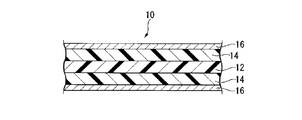
- FIG. 1 is a schematic cross-sectional view showing an example of a laminated board of the present invention.
- the laminated plate 10 includes a heat-resistant resin layer 12, a fluorine-containing resin layer 14 laminated on the first surface of the heat-resistant resin layer 12, and the fluorine-containing resin layer 14 on the side opposite to the heat-resistant resin layer 12. And a metal foil layer 16 laminated on the surface.
- FIG. 2 is a schematic cross-sectional view showing another example of the laminate of the present invention.
- the laminated plate 10 includes a heat resistant resin layer 12, two fluorine-containing resin layers 14 laminated on the first surface and the second surface of the heat resistant resin layer 12, and the heat resistance of each fluorine-containing resin layer 14. It has two metal foil layers 16 laminated on the surface opposite to the resin layer 12.
- the thickness of the laminate of the present invention is usually from 10 to 2500 ⁇ m, preferably from 12 to 300 ⁇ m, more preferably from 18 to 150 ⁇ m, even more preferably from 20 to 100 ⁇ m from the viewpoint of use for a flexible printed circuit board.
- the heat-resistant resin layer is a layer made of a heat-resistant resin film, which will be described later, and includes a heat-resistant resin (B) (excluding the fluorine-containing resin (A)).
- the heat resistant resin layer may contain an additive and the like to be described later as long as the effects of the present invention are not impaired.
- the heat resistant resin layer may have a single layer structure or a laminated structure of two or more layers.
- the thickness of the heat resistant resin layer is preferably 3 to 500 ⁇ m, more preferably 5 to 200 ⁇ m, and further preferably 6 to 50 ⁇ m. If the thickness of the heat resistant resin layer is equal to or greater than the lower limit, the electrical insulation is excellent. If the thickness of the heat-resistant resin layer is not more than the above upper limit value, the entire thickness of the laminate can be reduced.
- the content of the heat resistant resin (B) in the heat resistant resin layer is preferably 50% by mass or more, preferably 80% by mass or more, out of 100% by mass of the heat resistant resin layer, from the viewpoint of heat resistance of the heat resistant resin layer. Is more preferable.
- the upper limit of this content is not specifically limited, 100 mass% may be sufficient.
- heat resistant resin (B) examples include polyimide (aromatic polyimide, etc.), polyarylate, polysulfone, polyallylsulfone (polyethersulfone, etc.), aromatic polyamide, aromatic polyether amide, polyphenylene sulfide, polyallyl ether ketone. , Polyamideimide, liquid crystal polyester and the like.
- polyimide As the heat resistant resin (B), polyimide is preferable.
- the polyimide may be a thermosetting polyimide or a thermoplastic polyimide.
- aromatic polyimide is preferable.
- the aromatic polyimide is preferably a wholly aromatic polyimide produced by condensation polymerization of an aromatic polycarboxylic dianhydride and an aromatic diamine.
- Polyimide is usually obtained via polyamic acid (polyimide precursor) by reaction (polycondensation) of polycarboxylic dianhydride (or its derivative) and diamine.
- Polyimides especially aromatic polyimides, are insoluble in solvents and the like due to their rigid main chain structure and have infusible properties. Therefore, first, a polyimide precursor (polyamic acid or polyamic acid) that is soluble in an organic solvent is synthesized by a reaction between a polyvalent carboxylic dianhydride and a diamine, and molding processing can be performed by various methods at the polyamic acid stage. Done. Thereafter, the polyamic acid is subjected to a dehydration reaction by heating or a chemical method to be cyclized (imidized) to obtain a polyimide.
- aromatic polycarboxylic dianhydride examples include, for example, those described in JP-A-2012-145676, [0055]. Further, ethylene tetracarboxylic dianhydride and cyclopentane tetracarboxylic dianhydride, which are non-aromatic polyvalent carboxylic dianhydrides, can be used as well as aromatic ones.
- One type of polyvalent carboxylic acid dianhydride may be used alone, or two or more types may be used in combination.
- aromatic diamine examples include, for example, those described in JP-A-2012-145676, [0057].
- An aromatic diamine may be used individually by 1 type, and may use 2 or more types together.
- the heat resistant resin layer may contain an additive.
- an inorganic filler having a low dielectric constant and dielectric loss tangent is preferable.
- Inorganic fillers include silica, clay, talc, calcium carbonate, mica, diatomaceous earth, alumina, zinc oxide, titanium oxide, calcium oxide, magnesium oxide, iron oxide, tin oxide, antimony oxide, calcium hydroxide, magnesium hydroxide, water Aluminum oxide, basic magnesium carbonate, magnesium carbonate, zinc carbonate, barium carbonate, dosonite, hydrotalcite, calcium sulfate, barium sulfate, calcium silicate, montmorillonite, bentonite, activated clay, sepiolite, imogolite, sericite, glass fiber, glass Examples thereof include beads, silica-based balloons, carbon black, carbon nanotubes, carbon nanohorns, graphite, carbon fibers, glass balloons, carbon burns, wood flour, and zinc borate.
- An inorganic filler may be used individually by 1 type,
- the inorganic filler may be porous or non-porous, and is preferably porous from the viewpoint of lower dielectric constant and dielectric loss tangent.
- the inorganic filler may be subjected to a surface treatment with a surface treatment agent such as a silane coupling agent or a titanate coupling agent from the viewpoint of improving dispersibility in the resin.
- the content of an additive such as an inorganic filler in the heat resistant resin layer is preferably 0.1 to 100 parts by mass, more preferably 0.1 to 60 parts by mass with respect to 100 parts by mass of the heat resistant resin (B). .
- the fluorine-containing resin layer is a layer made of a fluorine-containing resin film described later, and includes a specific fluorine-containing resin (A).
- the fluorine-containing resin layer may contain other resins, additives and the like as long as the effects of the present invention are not impaired.
- the fluorine-containing resin layer may have a single layer structure or a laminated structure of two or more layers.
- the thickness of the fluororesin layer is usually 1 to 1000 ⁇ m, preferably 1 to 20 ⁇ m, more preferably 3 to 20 ⁇ m, and further preferably 3 to 15 ⁇ m from the viewpoint of heat resistance against a soldering iron or the like. If the thickness of the fluorine-containing resin layer is not more than the above upper limit value, the entire thickness of the laminate can be reduced. If the thickness of the fluororesin layer is not less than the above lower limit value, the fluororesin layer will expand (foam) due to heat when the heat-resistant resin layer is exposed to an atmosphere corresponding to solder reflow at a high temperature. It is difficult and has excellent electrical insulation.
- the fluorine-containing resin layer may be laminated only on the first surface of the heat resistant resin layer, or may be laminated on the first surface and the second surface of the heat resistant resin layer. From the standpoint of obtaining a double-sided metal-clad laminate with excellent electrical reliability that suppresses warpage of the laminate, a fluorine-containing resin layer is laminated on the first surface and the second surface of the heat-resistant resin layer. Is preferred.
- the composition of each fluorine-containing resin layer (type of fluorine-containing resin (A), types of other resins and additives, and , Their contents, etc.) and thickness may be the same or different. From the viewpoint of suppressing the warpage of the laminate, the composition and thickness of each fluororesin layer are preferably the same.
- the fluorine-containing resin (A) contained in a fluorine-containing resin layer may be sufficient as the fluorine-containing resin (A) contained in a fluorine-containing resin layer, and 2 or more types may be sufficient as it.
- the content of the fluorine-containing resin (A) in the fluorine-containing resin layer is 100% by mass of the fluorine-containing resin layer from the viewpoint of adhesive strength at the interface between the fluorine-containing resin layer and the heat-resistant resin layer or the metal foil layer. Among these, 50 mass% or more is preferable and 80 mass% or more is more preferable.
- the upper limit of content of a fluorine-containing resin (A) is not specifically limited, 100 mass% may be sufficient.
- the fluorine-containing resin (A) has at least one functional group selected from the group consisting of a carbonyl group-containing group, a hydroxy group, an epoxy group, and an isocyanate group (hereinafter referred to as functional group (I)). Resin.
- functional group (I) By having the functional group (I), the adhesive strength at the interface between the fluorine-containing resin layer containing the fluorine-containing resin (A) and the heat-resistant resin layer or the metal foil layer is increased.
- the functional group (I) is composed of end groups of the main chain and pendant groups of the main chain of the fluorine-containing resin (A). It is preferably present as either one or both.
- the functional group (I) may be one type or two or more types.
- the fluororesin (A) preferably has at least a carbonyl group-containing group as the functional group (I) from the viewpoint of adhesive strength at the interface between the fluororesin layer and the heat-resistant resin layer or metal foil layer.
- the carbonyl group-containing group include a group having a carbonyl group between carbon atoms of a hydrocarbon group, a carbonate group, a carboxy group, a haloformyl group, an alkoxycarbonyl group, an acid anhydride group, and the like.
- Examples of the hydrocarbon group in the group having a carbonyl group between carbon atoms of the hydrocarbon group include alkylene groups having 2 to 8 carbon atoms.
- carbon number of this alkylene group is carbon number in the state which does not contain a carbonyl group.
- the alkylene group may be linear or branched.
- the haloformyl group is represented by —C ( ⁇ O) —X (where X is a halogen atom).
- Examples of the halogen atom in the haloformyl group include a fluorine atom and a chlorine atom, and a fluorine atom is preferable.
- the haloformyl group is preferably a fluoroformyl group (also referred to as a carbonyl fluoride group).
- the alkoxy group in the alkoxycarbonyl group may be linear or branched and is preferably an alkoxy group having 1 to 8 carbon atoms, particularly preferably a methoxy group or an ethoxy group.
- the content of the functional group (I) in the fluororesin (A) is preferably 10 to 60000, more preferably 100 to 50000, relative to 1 ⁇ 10 6 main chain carbon atoms of the fluororesin (A). 100 to 10,000 is more preferable, and 300 to 5000 is particularly preferable. If content of functional group (I) is more than the said lower limit, the adhesive strength in the interface of a fluorine-containing resin layer and a heat resistant resin layer or a metal foil layer will become still higher. If the content of the functional group (I) is not more than the above upper limit value, the adhesive strength at the interface between the fluorine-containing resin layer and the heat-resistant resin layer or metal foil layer can be increased even if the temperature of the thermal laminate is lowered. .
- the content of the functional group (I) can be measured by methods such as nuclear magnetic resonance (NMR) analysis and infrared absorption spectrum analysis.
- NMR nuclear magnetic resonance
- the proportion of units having the functional group (I) in all units constituting the fluororesin (A) using a method such as infrared absorption spectrum analysis as described in JP-A-2007-314720 ( Mol%) and the content of the functional group (I) can be calculated from the ratio.
- the melting point of the fluororesin (A) is preferably 260 to 320 ° C, more preferably 295 to 315 ° C, and further preferably 295 to 310 ° C.
- the melting point of the fluororesin (A) can be adjusted by the type and ratio of units constituting the fluororesin (A), the molecular weight of the fluororesin (A), and the like. For example, the melting point tends to increase as the proportion of the unit (u1) described later increases.
- the fluorine-containing resin (A) a resin that can be melt-molded is preferable from the viewpoint of easily producing a fluorine-containing resin film described later.
- known fluorine-containing resins that can be melt-molded tetrafluoroethylene / fluoroalkyl vinyl ether copolymer, tetrafluoroethylene / hexafluoropropylene copolymer, ethylene / tetra
- the fluorine-containing resin (A) has a melt flow rate of 0.1 to 1000 g / 10 min (preferably 0.5) at a temperature of 20 ° C. or higher than the melting point of the fluorine-containing resin (A) under a load of 49 N. Those having a temperature of ⁇ 100 g / 10 min, more preferably 1-30 g / 10 min, still more preferably 5-20 g / 10 min) are preferred.
- the melt flow rate is at least the lower limit, the moldability of the fluororesin (A) is excellent, and the surface smoothness and appearance of the fluororesin layer are excellent.
- the melt flow rate is equal to or less than the upper limit, the mechanical strength of the fluororesin layer is excellent.
- the melt flow rate of the fluororesin (A) under the conditions of 372 ° C. and a load of 49 N is preferably 0.5 to 15 g / 10 minutes, more preferably 1 to 15 g / 10 minutes, and further preferably 1 to 12 g / 10 minutes. preferable. If the melt flow rate is less than or equal to the upper limit, the soldering iron heat resistance tends to be improved. When the melt flow rate is equal to or higher than the lower limit, the moldability of the fluororesin (A) is excellent.
- the melt flow rate is a measure of the molecular weight of the fluorine-containing resin (A).
- the molecular weight of the fluorinated resin (A) and thus the melt flow rate can be adjusted by the production conditions of the fluorinated resin (A). For example, if the polymerization time is shortened during the polymerization of the monomer, the melt flow rate tends to increase.
- Examples of the fluororesin (A) include the following, depending on the production method.
- ( ⁇ ) A fluorine-containing polymer having a functional group (I) derived from at least one selected from the group consisting of a monomer, a chain transfer agent and a polymerization initiator used in the production of the polymer.
- ( ⁇ ) A fluorine-containing resin in which a functional group (I) is introduced into a fluorine-containing resin having no functional group (I) by surface treatment such as corona discharge treatment or plasma treatment.
- ( ⁇ ) A fluorine-containing resin obtained by graft polymerization of a monomer having a functional group (I) to a fluorine-containing resin having no functional group (I).
- the fluorine-containing resin (A) is preferably a fluorine-containing polymer ( ⁇ ) for the following reasons.
- the functional group (I) is present in either one or both of the end group of the main chain and the pendant group of the main chain of the fluorinated polymer ( ⁇ ).
- the adhesive strength at the interface between the layer and the heat resistant resin layer or metal foil layer is further increased.
- the functional group (I) in the fluororesin ( ⁇ ) is unstable because it is formed by the surface treatment and easily disappears with time.
- the fluoropolymer ( ⁇ ) is obtained by the following method (1) Can be manufactured.
- the functional group (I) is present in a unit derived from the monomer formed by polymerization of the monomer during production.
- Method (1) A monomer having a functional group (I) is used when the fluoropolymer ( ⁇ ) is produced by polymerization of monomers.
- the fluoropolymer ( ⁇ ) is obtained by the following method (2) Can be manufactured.
- the functional group (I) exists as a terminal group of the main chain of the fluoropolymer ( ⁇ ).
- Method (2) A fluoropolymer ( ⁇ ) is produced by polymerizing monomers in the presence of a chain transfer agent having a functional group (I). Examples of the chain transfer agent having the functional group (I) include acetic acid, acetic anhydride, methyl acetate, ethylene glycol, propylene glycol and the like.
- the fluoropolymer ( ⁇ ) is obtained by the following method (3): Can be manufactured.
- the functional group (I) exists as a terminal group of the main chain of the fluoropolymer ( ⁇ ).
- radical polymerization initiator having a functional group (I) examples include di-n-propyl peroxydicarbonate, diisopropyl peroxycarbonate, tert-butyl peroxyisopropyl carbonate, bis (4-tert-butylcyclohexyl) peroxydicarbonate, di-2 -Ethylhexyl peroxydicarbonate and the like.
- the fluoropolymer ( ⁇ ) can be produced by using two or more of the above methods (1) to (3) in combination.
- the fluorine-containing polymer ( ⁇ ) the content of the functional group (I) can be easily controlled. Therefore, the single polymer produced by the method (1) is easy to adjust the adhesive strength with the metal foil layer.
- a fluorine-containing polymer ( ⁇ ) having a functional group (I) derived from a monomer is preferred.
- the fluorine-containing polymer ( ⁇ ) having a functional group (I) derived from a monomer the adhesive strength at the interface between the fluorine-containing resin layer and the heat-resistant resin layer or the metal foil layer is further increased.
- the following fluoropolymer ( ⁇ 1) is particularly preferred.
- TFE tetrafluoroethylene
- u2 a unit cyclic hydrocarbon monomer having an acid anhydride group
- a fluorine-containing monomer provided that , A fluoropolymer ( ⁇ 1) having a unit (u3) derived from TFE.
- Monomers constituting the unit (u2) include itaconic anhydride (hereinafter also referred to as “IAH”), citraconic anhydride (hereinafter also referred to as “CAH”), 5-norbornene-2,3-dicarboxylic acid. Examples thereof include acid anhydrides (hereinafter also referred to as “NAH”), maleic anhydride, and the like. These monomers may be used alone or in combination of two or more.
- the monomer constituting the unit (u2) is preferably at least one selected from the group consisting of IAH, CAH and NAH.
- a fluorine-containing polymer ( ⁇ 1) having an acid anhydride group can be easily produced without using a special polymerization method required when maleic anhydride is used (see JP-A-11-19312). it can.
- the monomer constituting the unit (u2) is preferably NAH because the adhesive strength at the interface between the fluorine-containing resin layer and the heat-resistant resin layer or metal foil layer is further increased.
- the fluorine-containing monomer constituting the unit (u3) is preferably a fluorine-containing compound having one polymerizable carbon-carbon double bond.
- fluoroolefin vinyl fluoride, vinylidene fluoride (hereinafter referred to as “VdF”).
- VdF vinylidene fluoride
- Trifluoroethylene chlorotrifluoroethylene
- HFP hexafluoropropylene
- CF 2 CFOCF 2 CF 2 CF 3 (hereinafter also referred to as “PPVE”) is preferable.
- CH 2 CX 3 (CF 2 ) q X 4
- CH 2 CH (CF 2 ) 2 F
- CH 2 CH (CF 2 ) 3 F
- CH 2 CH (CF 2 ) 4 F
- CH 2 ⁇ CF (CF 2 ) 3 H CH 2 ⁇ CF (CF 2 ) 4 H and the like
- CH 2 ⁇ CH (CF 2 ) 4 F or CH 2 ⁇ CH (CF 2 ) 2 F are preferable.
- the proportion of the unit (u1) is preferably 50 to 99.89 mol%, more preferably 50 to 99.4 mol%, out of the total 100 mol% of the unit (u1), the unit (u2) and the unit (u3). 50 to 98.9 mol% is more preferable.
- the proportion of the unit (u2) is preferably 0.01 to 5 mol%, more preferably 0.1 to 3 mol%, out of the total 100 mol% of the unit (u1), the unit (u2) and the unit (u3). Preferably, 0.1 to 2 mol% is more preferable.
- the proportion of the unit (u3) is preferably from 0.1 to 49.99 mol%, out of the total of 100 mol% of the unit (u1), the unit (u2) and the unit (u3), and preferably from 0.5 to 49.9. Mole% is more preferable, and 1 to 49.9 mol% is more preferable.
- the fluororesin layer is excellent in heat resistance, chemical resistance and elastic modulus at high temperature.
- the ratio of the unit (u2) is within the above range, the amount of the acid anhydride group in the fluoropolymer ( ⁇ 1) is appropriate, and the interface between the fluororesin layer and the heat resistant resin layer or the metal foil layer. The adhesive strength at is further increased.
- the proportion of the unit (u3) is within the above range, the fluoropolymer ( ⁇ 1) is excellent in moldability and the fluororesin layer is excellent in bending resistance.
- the ratio of each unit can be calculated by melt NMR analysis, fluorine content analysis, infrared absorption spectrum analysis, etc. of the fluoropolymer ( ⁇ 1).
- the proportion of units (u2) is 0.01 mol%. This corresponds to the content of acid anhydride groups in) being 100 with respect to 1 ⁇ 10 6 main chain carbon atoms of the fluoropolymer ( ⁇ 1).
- the proportion of the unit (u2) is 5 mol% because the content of the acid anhydride group in the fluoropolymer ( ⁇ 1) is 1 ⁇ 10 6 main chain carbon atoms of the fluoropolymer ( ⁇ 1). This corresponds to 50,000 pieces.
- a part of the acid anhydride group in the unit (u2) is hydrolyzed, and as a result, a dicarboxylic acid (itaconic acid, Units derived from citraconic acid, 5-norbornene-2,3-dicarboxylic acid, maleic acid, etc.) may be included.
- a dicarboxylic acid (itaconic acid, Units derived from citraconic acid, 5-norbornene-2,3-dicarboxylic acid, maleic acid, etc.) may be included.
- the ratio of the unit is included in the ratio of the unit (u2).
- the fluorinated polymer ( ⁇ 1) is a unit derived from a non-fluorinated monomer (excluding an acid anhydride group-containing cyclic hydrocarbon monomer) ( u4) may be included.
- a non-fluorinated monomer a non-fluorinated compound having one polymerizable carbon-carbon double bond is preferable.
- a non-fluorine-containing monomer may be used individually by 1 type, and may use 2 or more types together.
- the non-fluorinated monomer ethylene, propylene, or vinyl acetate is preferable, and ethylene is particularly preferable.
- the proportion of the unit (u4) is 5 to 5% with respect to 100 mol% in total of the unit (u1), the unit (u2), and the unit (u3). 90 mol% is preferable, 5 to 80 mol% is more preferable, and 10 to 65 mol% is further preferable.
- the total of the units (u1), units (u2), and units (u3) is preferably 60 mol% or more, and 65 mol% or more. Is more preferable, and 68 mol% or more is more preferable. A preferable upper limit is 100 mol%.
- the fluorine-containing resin (A) can be produced by a conventional method.
- the polymerization method is preferably a method using a radical polymerization initiator.
- Polymerization methods include bulk polymerization, solution polymerization using organic solvents (fluorinated hydrocarbons, chlorinated hydrocarbons, fluorinated chlorohydrocarbons, alcohols, hydrocarbons, etc.), aqueous media and appropriate organic solvents as required.
- suspension polymerization methods using an aqueous medium and an emulsion polymerization method using an emulsifier and a solution polymerization method are preferred.
- radical polymerization initiator an initiator having a half-life of 10 hours and a temperature of 0 to 100 ° C. is preferable, and an initiator having a temperature of 20 to 90 ° C. is more preferable.
- radical polymerization initiators include azo compounds (azobisisobutyronitrile, etc.), non-fluorinated diacyl peroxides (isobutyryl peroxide, octanoyl peroxide, benzoyl peroxide, lauroyl peroxide, etc.), peroxydicarbonates (diisopropyl peroxydicarbonate).
- Peroxyesters tert-butylperoxypivalate, tert-butylperoxyisobutyrate, tert-butylperoxyacetate, etc.
- fluorine-containing diacyl peroxide ((Z (CF 2 ) r COO) 2 (where Z is A hydrogen atom, a fluorine atom or a chlorine atom, and r is an integer of 1 to 10)
- inorganic peroxides potassium persulfate, sodium persulfate, ammonium persulfate, etc.
- a chain transfer agent may be used to control the melt viscosity of the fluororesin (A).
- Chain transfer agents include alcohol (methanol, ethanol, etc.), chlorofluorohydrocarbon (1,3-dichloro-1,1,2,2,3-pentafluoropropane, 1,1-dichloro-1-fluoroethane, etc. ), Hydrocarbons (pentane, hexane, cyclohexane, etc.).
- Examples of the organic solvent used in the solution polymerization method include perfluorocarbon, hydrofluorocarbon, chlorohydrofluorocarbon, and hydrofluoroether.
- the number of carbon atoms is preferably 4-12.
- Specific examples of the perfluorocarbon include perfluorocyclobutane, perfluoropentane, perfluorohexane, perfluorocyclopentane, and perfluorocyclohexane.
- Specific examples of the hydrofluorocarbon include 1-hydroperfluorohexane.
- Specific examples of the chlorohydrofluorocarbon include 1,3-dichloro-1,1,2,2,3-pentafluoropropane.
- Specific examples of the hydrofluoroether include methyl perfluorobutyl ether, 2,2,2-trifluoroethyl 2,2,1,1-tetrafluoroethyl ether, and the like.
- the polymerization temperature is preferably 0 to 100 ° C, more preferably 20 to 90 ° C.
- the polymerization pressure is preferably from 0.1 to 10 MPa, more preferably from 0.5 to 3 MPa.
- the polymerization time is preferably 1 to 30 hours.
- the concentration of the monomer constituting the unit (u2) during polymerization is preferably 0.01 to 5 mol%, preferably 0.1 to 3 mol% is more preferable, and 0.1 to 2 mol% is more preferable.
- the concentration of the monomer is within the above range, the polymerization rate becomes moderate.
- the concentration of the monomer is too high, the polymerization rate tends to decrease.
- the monomer constituting the unit (u2) is consumed in the polymerization, the consumed amount is continuously or intermittently supplied into the polymerization tank, and the concentration of the monomer is maintained within the above range. It is preferable.
- resins contained in the heat resistant resin layer are not particularly limited as long as the electrical reliability characteristics are not impaired.
- examples of other resins include fluorine-containing resins other than the fluorine-containing resin (A), aromatic polyesters, polyamideimides, and thermoplastic polyimides. Of these, fluorine-containing copolymers other than the fluorine-containing resin (A) are preferable from the viewpoint of electrical reliability.
- Examples of the fluorine-containing resin other than the fluorine-containing resin (A) include a tetrafluoroethylene / fluoroalkyl vinyl ether copolymer, a tetrafluoroethylene / hexafluoropropylene copolymer, and an ethylene / tetrafluoroethylene copolymer.
- the melting point of the fluorine-containing resin other than the fluorine-containing resin (A) is preferably 280 to 320 ° C. When the melting point is within the above range, swelling (foaming) due to heat hardly occurs in the fluororesin layer when exposed to an atmosphere corresponding to solder reflow.
- Examples of the additive contained in the heat resistant resin layer include the same additives as those contained in the heat resistant resin layer, and preferred forms thereof are also the same.
- the metal foil layer is a layer made of a metal foil.
- Metal foil is not specifically limited, What is necessary is just to select suitably according to the use of a laminated board.
- examples of the material of the metal foil include copper or a copper alloy, stainless steel or an alloy thereof, nickel or a nickel alloy (including 42 alloy), aluminum or an aluminum alloy. It is done.
- copper foil such as rolled copper foil and electrolytic copper foil is frequently used, and copper foil is also suitable in the present invention.
- a rust prevention layer (oxide film such as chromate) or a heat-resistant layer may be formed on the surface of the metal foil.
- a coupling agent process etc. to the surface of metal foil.
- the thickness of metal foil is not specifically limited, What is necessary is just the thickness which can exhibit a sufficient function according to the use of a laminated board.
- the fluorine-containing resin layer has at least one functional group (I) selected from the group consisting of a carbonyl group-containing group, a hydroxy group, an epoxy group, and an isocyanate group. Since (A) is included, the adhesive strength at the interface between the heat-resistant resin layer and the fluorine-containing resin layer and the interface between the fluorine-containing resin layer and the metal foil layer is sufficiently high.
- the manufacturing method of the laminated board of this invention has the following process (a) and process (b), and also the process (x), process (y), and process (z) implemented as needed.
- a step of obtaining a metal foil with a fluorine-containing resin layer by thermally laminating a fluorine-containing resin film containing the fluorine-containing resin (A) and a metal foil at a temperature lower than the melting point of the fluorine-containing resin (A).
- (X) The process of correcting the curvature of the metal foil with a fluorine-containing resin layer.
- the thermal lamination in the step (a) and the thermal lamination in the step (b) are continuously performed by a thermal laminating apparatus having a thermal laminating unit composed of a pair of metal rolls or a pair of metal belts. Preferably, it is done.
- the heat laminating apparatus having a pair of metal rolls include a heat roll laminating apparatus.
- a double belt press etc. are mentioned as a heat laminating apparatus which has a pair or more metal belt.
- the thermal laminating apparatus a hot roll laminating apparatus is preferable because the apparatus configuration is simple and it is advantageous in terms of maintenance cost.
- the hot roll laminating apparatus may be an apparatus having a pair of metal rolls that can be crimped while heating two members, and the specific apparatus configuration is not particularly limited.
- the heating method in the heat laminating means is not particularly limited, and for example, a conventionally known method capable of heating at a predetermined temperature such as a heat circulation method, a hot air heating method, an induction heating method, or the like can be adopted.
- the pressurization method in the heat laminating means is not particularly limited, and for example, a conventionally known method that can apply a predetermined pressure, such as a hydraulic method, a pneumatic method, and a gap pressure method can be adopted.
- the thermal laminating apparatus may be provided with a feeding means for sending out each member before the thermal laminating means (a pair of metal rolls or the like), and a winding means for winding the bonded members after the thermal laminating means. May be provided. Productivity can be further improved by providing the feeding means and winding means for each member. Specific configurations of the feeding means and the winding means of each member are not particularly limited, and examples thereof include a known winder that can wind each member in a roll shape.
- the heat laminating apparatus is provided with a feeding means for sending out a protective material disposed between the heat laminating means and the metal foil and a winding means for winding up the protective material. May be.
- the protective material feeding means and the winding means the protective material can be reused by winding the protective material once used and installing it again on the delivery side.
- end position detecting means and winding position correcting means may be provided in order to align both ends of the protective material. Thereby, the end portions of the protective material can be aligned and wound with high accuracy, and the efficiency of reuse can be increased.
- Specific configurations of the protective material feeding means, the winding means, the end position detecting means, and the winding position correcting means are not particularly limited, and examples thereof include various conventionally known devices.
- the protective material is not particularly limited as long as it can withstand the heating temperature at the time of thermal lamination, and heat resistant plastic film (non-thermoplastic polyimide film, etc.), metal foil (copper foil, aluminum foil, SUS foil, etc.) Etc.
- a non-thermoplastic polyimide film is preferred from the viewpoint of excellent balance between heat resistance and reusability.
- the thickness of the non-thermoplastic polyimide film is preferably 75 ⁇ m or more. If the thickness of the non-thermoplastic polyimide film is thin, there is a risk that the role of buffering and protection during thermal lamination will not be sufficiently fulfilled.
- the protective material may have a single layer structure or a multilayer structure of two or more layers.
- a metal foil with a fluorine-containing resin layer is obtained by thermally laminating a fluorine-containing resin film and a metal foil.
- the fluorine-containing resin film should just contain a fluorine-containing resin (A).
- the fluorine-containing resin film may be a single layer film or a laminated film.
- the thickness of the fluororesin film is usually 1 to 1000 ⁇ m, preferably 1 to 20 ⁇ m, more preferably 3 to 20 ⁇ m, and further preferably 3 to 15 ⁇ m.
- a fluorine-containing resin film is obtained by the following method, for example.
- the fluorine-containing resin film is preferably subjected to a heat treatment at a temperature of preferably 100 to 250 ° C., more preferably 150 to 250 ° C., still more preferably 180 to 250 ° C., and particularly preferably a temperature of the heat laminate to 250 ° C. or less. .
- a heat treatment By performing the heat treatment in advance, shrinkage of the fluorine-containing resin film in the step (a) can be reduced, and as a result, warpage of the metal foil with the fluorine-containing resin layer can be reduced.
- FIG. 3 is a schematic configuration diagram showing an example of a hot roll laminating apparatus used in the step (a).
- a hot roll laminating apparatus 20 a long fluorine-containing resin film 14 ′ continuously fed from the roll 22 and a long metal foil 16 ′ continuously fed from the roll 24 are a pair of metals.
- the rolls 26 are overlapped and heated and pressed when continuously passing between the pair of metal rolls 26 to be heat-laminated to form a metal foil 18 with a fluororesin layer.
- the metal foil 18 with a fluororesin layer that has passed between the pair of metal rolls 26 is continuously wound around the roll 28.
- the temperature of the metal roll or metal belt that is, the temperature of the thermal lamination is less than the melting point of the fluororesin (A), preferably (melting point ⁇ 20 ° C.) or less, more preferably (melting point ⁇ 50 ° C.) or less. If the temperature of the heat laminate is not more than the above upper limit value, it is difficult to shrink in the width direction at the moment when the fluorine-containing resin film is heated, and it is difficult to cut. Further, the fluorine-containing resin film hardly adheres to the metal roll or the metal belt.
- the temperature of the thermal laminate is preferably (melting point of the fluororesin (A) ⁇ 200 ° C.) or more, more preferably (melting point ⁇ 180 ° C.) or more, and further preferably (melting point ⁇ 150 ° C.) or more. If the temperature of the thermal laminate is equal to or higher than the lower limit, the fluororesin film and the metal foil are temporarily bonded, and the fluororesin layer and the metal foil are unlikely to peel off in a subsequent process.
- the pressure between the pair of metal rolls or the pressure between the pair of metal belts is preferably 49 to 1764 N / cm, more preferably 98 to 1470 N / cm. If the pressure of the heat laminate is within the above range, the three conditions of the temperature of the heat laminate, the speed of the heat laminate, and the pressure of the heat laminate can be made favorable, and the productivity can be further improved.
- the heat laminating speed is preferably 0.5 m / min or more, and more preferably 1.0 m / min or more. If the thermal lamination speed is 0.5 m / min or more, sufficient thermal lamination is possible. If the heat laminating speed is 1.0 m / min or more, the productivity can be further improved.
- the adhesive strength at the interface between the fluororesin layer and the metal foil is preferably 0.1 N / cm or more, more preferably 0.2 N / cm or more, and further preferably 0.3 N / cm or more. . If the adhesive strength is equal to or higher than the lower limit, peeling between the fluororesin layer and the metal foil is unlikely to occur in the subsequent process.
- the warp of the metal foil with a fluorine-containing resin layer can be suppressed by reducing the thickness of the fluorine-containing resin film or lowering the temperature of the thermal laminate. Nevertheless, if warpage occurs in the metal foil with a fluorinated resin layer in the step (a), the warpage of the metal foil with a fluorinated resin layer is performed by performing the step (x) before the step (b). You may correct it.
- the correction of the warpage of the metal foil with a fluororesin layer in the step (x) is preferably 100 to 250 ° C., more preferably 150 to 250 ° C., still more preferably 180 to 250 ° C.
- the heat treatment is carried out at a temperature of the heat laminating temperature or higher and 250 ° C. or lower.
- a heat-resistant resin film and a metal foil with a fluorine-containing resin layer are thermally laminated so that the heat-resistant resin film and the fluorine-containing resin layer are in contact with each other to obtain a laminate.
- the metal foil with a fluorine-containing resin layer may be disposed only on the first surface of the heat resistant resin film, or disposed on the first surface and the second surface of the heat resistant resin film. May be.
- the heat resistant resin film only needs to contain the heat resistant resin (B), and may be a single layer film or a laminated film.
- the thickness of the heat resistant resin film is preferably 3 to 500 ⁇ m, more preferably 5 to 200 ⁇ m, and further preferably 6 to 50 ⁇ m.
- the heat-resistant resin film is formed into a film shape by a known molding method (extrusion molding method, inflation molding method, etc.) using the heat-resistant resin (B) itself or a resin composition containing the heat-resistant resin (B). Obtained by the method.
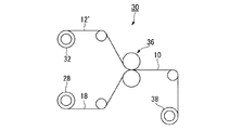
- FIG. 4 is a schematic configuration diagram showing an example of a hot roll laminating apparatus used in the step (b).
- the hot roll laminating apparatus 30 continuous from a long heat-resistant resin film 12 ′ continuously fed from a roll 32 and a roll 28 in which the metal foil 18 with a fluororesin layer is wound up in the step (a).
- the metal foil 18 with the long fluorine-containing resin layer fed to the pair of metal rolls 36 is superposed on the pair of metal rolls 36 and is heated and pressurized when continuously passing between the pair of metal rolls 36.
- the laminated plate 10 that has passed between the pair of metal rolls 36 is continuously wound around the roll 38.
- the temperature of the metal roll or metal belt that is, the temperature of the thermal lamination is not less than the melting point of the fluororesin (A), preferably (melting point + 10 ° C.) or more, and more preferably (melting point + 20 ° C.) or more. If the temperature of the heat laminating is not more than the above upper limit value, the heat resistant resin film and the metal foil with a fluorine-containing resin layer can be heat laminated well. If the temperature of the thermal laminate is (melting point + 20 ° C.) or higher, the speed of the thermal laminate can be increased to further improve the productivity.
- the temperature of the thermal laminate is preferably 420 ° C. or lower, and more preferably 400 ° C. or lower.
- the pressure between the pair of metal rolls or the pressure between the pair of metal belts is preferably 49 to 1764 N / cm, and more preferably 98 to 1600 N / cm. If the pressure of the heat laminate is within the above range, the three conditions of the temperature of the heat laminate, the speed of the heat laminate, and the pressure of the heat laminate can be made favorable, and the productivity can be further improved.
- the heat laminating speed is preferably 0.5 m / min or more, and more preferably 1.0 m / min or more. If the thermal lamination speed is 0.5 m / min or more, sufficient thermal lamination is possible. If the heat laminating speed is 1.0 m / min or more, the productivity can be further improved.
- the adhesive strength at the interface between the heat-resistant resin layer and the fluorine-containing resin layer in the laminate is preferably 5 N / cm or more, more preferably 6 N / cm or more, and even more preferably 7 N / cm or more.
- the adhesive strength at the interface between the fluororesin layer and the metal foil in the laminate is preferably 7 N / cm or more, more preferably 8 N / cm or more, and further preferably 10 N / cm or more.
- the warpage of the laminate may be corrected by performing the step (y).
- the correction of the warp of the laminate in the step (y) is preferably performed on the laminate at 100 to 250 ° C., more preferably 150 to 250 ° C., still more preferably 180 to 250 ° C., particularly preferably the temperature of the thermal laminate above 250 ° C.
- the heat treatment is performed.
- the step (z) is carried out and the laminated board is subjected to heat treatment to melt the fluorine-containing resin (A).
- the flow rate may be reduced.
- the heat treatment in the step (z) is performed using, for example, the above-described thermal laminating apparatus.
- the temperature of the heat treatment is preferably 370 ° C. or higher, and more preferably 380 ° C. or higher.
- the upper limit in this case is usually 420 ° C. or lower, preferably 400 ° C. or lower.
- a flexible printed circuit board which will be described later, can be obtained by subjecting the laminate to heat treatment at a temperature equal to or higher than the melting point of the fluororesin (A) in an environment with a low oxygen concentration in an inert gas atmosphere such as nitrogen or argon, or in a vacuum. Dimensional stability when passing through the solder reflow process and other heat treatment processes (coverlay mounting, etc.) is improved.
- the heat treatment conditions are preferably (melting point of fluororesin (A) + 10 ° C. to 120 ° C.) at a temperature of 5 seconds to 48 hours, more preferably (melting point of fluororesin (A) + 30 ° C. to 100 ° C.) For 30 seconds to 36 hours, more preferably (melting point of fluororesin (A) + 40 ° C. to 80 ° C.) for 1 minute to 24 hours.
- the heat treatment improves the adhesion between the metal foil and the fluorine-containing resin layer, and between the fluorine-containing resin layer and the heat-resistant resin film.
- a laminate having a sufficiently high adhesive strength at the interface can be obtained even if the pressure of the thermal laminate in steps (a) and (b) is lowered.
- the thermal laminating pressure can be lowered, so that the dimensional stability is improved. improves.
- the fluororesin film and the metal foil are thermally laminated at a temperature lower than the melting point of the fluororesin (A) in the step (a). It is hard to cut. And in the step (b), since the heat-resistant resin film and the metal foil with the fluorine-containing resin layer are thermally laminated at a melting point or higher of the fluorine-containing resin (A), the interface between the heat-resistant resin film and the fluorine-containing resin film , And the adhesive strength at the interface between the fluororesin film and the metal foil is sufficiently high. In the thermal lamination in the step (b), the fluororesin film is temporarily bonded to the metal foil and supported by the metal foil.
- the thermal lamination is performed at a temperature equal to or higher than the melting point of the fluororesin (A).
- the fluorine-containing resin film is difficult to heat shrink in the width direction and is not easily cut. From the above, it is possible to stably produce a laminate having a sufficiently high adhesive strength at the interface between the heat-resistant resin layer and the fluorine-containing resin layer and at the interface between the fluorine-containing resin layer and the metal foil layer.
- the flexible printed circuit board of the present invention includes a pattern circuit formed by removing unnecessary portions of the metal foil layer of the laminated board of the present invention by etching.
- the flexible printed circuit board of the present invention may be mounted with various miniaturized and densified components.
- the fluorine-containing resin layer has at least one functional group (I) selected from the group consisting of a carbonyl group-containing group, a hydroxy group, an epoxy group, and an isocyanate group. Since the resin (A) is contained, the adhesive strength at the interface between the heat-resistant resin layer and the fluorine-containing resin layer and the interface between the fluorine-containing resin layer and the metal foil layer is sufficiently high.
- Examples 1, 2 and 3 are examples, and examples 4 and 5 are comparative examples.
- the copolymer composition of the fluororesin (A) was determined by melt NMR analysis, fluorine content analysis, and infrared absorption spectrum analysis.
- the proportion of units derived from NAH having the functional group (I) in the fluororesin (A) was determined by the following infrared absorption spectrum analysis.
- the fluorine-containing resin (A) was press-molded to obtain a 200 ⁇ m film.
- an absorption peak in a unit derived from NAH in the fluororesin (A) appears at 1778 cm ⁇ 1 .
- the absorbance of the absorption peak was measured, and the ratio (mol%) of units derived from NAH was determined using the NAH molar extinction coefficient of 20810 mol ⁇ 1 ⁇ l ⁇ cm ⁇ 1 .
- the ratio to a (mol%) the number of functional groups (I) (acid anhydride group) relative to the main chain number 1 ⁇ 10 6 carbon atoms is calculated as [a ⁇ 10 6/100] Pieces.
- An evaluation sample was prepared by cutting a metal foil or laminate with a fluororesin layer into a size of 150 mm in length and 10 mm in width. The fluororesin layer and the metal foil were peeled from one end in the length direction of the evaluation sample to a position of 50 mm. Subsequently, it peeled so that it might become 90 degree
- the laminate was cut into a size of 150 mm in length and 10 mm in width to produce an evaluation sample.
- the heat-resistant resin layer and the fluorine-containing resin layer were peeled from one end in the length direction of the evaluation sample to a position of 50 mm. Subsequently, it peeled so that it might become 90 degree
- the NAH solution was continuously charged in an amount corresponding to 0.1 mol% with respect to the number of moles of TFE charged during the polymerization. After exceeding 8 hours from the start of polymerization, when 32 kg of TFE was charged, the temperature in the polymerization tank was lowered to room temperature and the pressure was purged to normal pressure. The obtained slurry was solid-liquid separated from AK225cb and then dried at 150 ° C. for 15 hours to obtain 33 kg of a fluororesin (A-1).
- the melting point of the fluororesin (A-1) was 305 ° C., and the melt flow rate was 11.0 g / 10 min.
- the content of the functional group (I) (an acid anhydride group) in the fluororesin (A-1) is 1000 with respect to 1 ⁇ 10 6 main chain carbon atoms of the fluororesin (A-1). there were.
- PFA TFE / perfluoro (alkyl vinyl ether) copolymer (Asahi Glass Co., Ltd., Fluon (registered trademark) PFA 73PT, melting point: 305 ° C., melt flow rate 13.6 g / 10 min).
- the fluororesin (A-1) was extrusion molded at a die temperature of 340 ° C. using a 30 mm ⁇ single-screw extruder having a 750 mm wide coat hanger die to obtain a fluororesin film 1 having a thickness of 25 ⁇ m.
- Fluorine-containing resin film 2 A fluorine-containing resin film 2 having a thickness of 12.5 ⁇ m was obtained in the same manner as the fluorine-containing resin film 1 except that the take-up speed was changed.
- Fluorine-containing resin film 3 PFA was extruded at a die temperature of 340 ° C. using a 30 mm ⁇ single screw extruder having a 750 mm wide coat hanger die to obtain a fluororesin film 3 having a thickness of 25 ⁇ m.
- Heat resistant resin film A polyimide film having a thickness of 25 ⁇ m (manufactured by Toray DuPont, Kapton (registered trademark) 100EN) was prepared.
- An electrolytic copper foil having a thickness of 12 ⁇ m (manufactured by Fukuda Metal Foil Powder Co., Ltd., CF-T4X-SVR-12, Rz: 1.2 ⁇ m) was prepared.
- the adhesive strength at the interface between the fluorine-containing resin layer and the metal foil layer was 11 N / cm, and the adhesive strength at the interface between the heat-resistant resin layer and the fluorine-containing resin layer was 8 N / cm.
- Example 2 A metal foil 2 with a fluorine-containing resin layer was produced in the same manner as in Example 1 except that the fluorine-containing resin film 2 was used instead of the fluorine-containing resin film 1.
- the adhesive strength at the interface between the fluorine-containing resin layer and the metal foil layer was 0.3 N / cm.
- the adhesive strength at the interface between the fluorine-containing resin layer and the metal foil layer was 10 N / cm, and the adhesive strength at the interface between the heat-resistant resin layer and the fluorine-containing resin layer was 7 N / cm.
- Example 3 The laminated board 2 obtained in Example 2 was subjected to heat treatment to produce a laminated board 3.
- the heat treatment was performed using a thermal laminator under conditions of a temperature of 380 ° C., a pressure of 1470 N / cm, and a speed of 1 m / min.
- the adhesive strength at the interface between the fluorine-containing resin layer and the metal foil layer of the laminate 3 was 12 N / cm, and the adhesive strength at the interface between the heat-resistant resin layer and the fluorine-containing resin layer was 10 N / cm.
- Example 4 An attempt was made to produce a metal foil with a fluorine-containing resin layer in the same manner as in Example 1 except that the fluorine-containing resin film 3 was used instead of the fluorine-containing resin film 1, but the interface between the fluorine-containing resin layer and the metal foil layer was attempted. When the metal foil with a fluorine-containing resin layer was wound up, separation occurred between the fluorine-containing resin film 3 and the metal foil.
- Example 5 An attempt was made to heat laminate the fluororesin film 1, metal foil and polyimide film using a heat roll laminator having a pair of metal rolls at a temperature of 400 ° C., a pressure of 784 N / cm, and a speed of 4 m / min. Since the heat shrinkage of the fluororesin film 1 was large in the vicinity of the roll and the fluororesin film 1 was broken, the laminated plate could not be produced continuously.
- the laminate obtained by the laminate production method of the present invention is useful for producing a flexible printed circuit board that requires a high degree of electrical reliability.
Landscapes
- Engineering & Computer Science (AREA)
- Microelectronics & Electronic Packaging (AREA)
- Mechanical Engineering (AREA)
- Manufacturing & Machinery (AREA)
- Laminated Bodies (AREA)
- Lining Or Joining Of Plastics Or The Like (AREA)
Abstract
Description
(1)耐熱性樹脂フィルムと金属箔とを、酸無水物基を有する含フッ素重合体を含む含フッ素樹脂フィルムを介して貼り合わせたフレキシブル金属張積層板(特許文献1)。
(2)耐熱性樹脂フィルムの表面および含フッ素樹脂フィルムの表面を低温プラズマ処理した後、耐熱性樹脂フィルムと金属箔とを、含フッ素樹脂フィルムを介して貼り合わせたフレキシブル金属張積層板(特許文献2)。
[1]耐熱性樹脂層と、該耐熱性樹脂層に接する含フッ素樹脂層と、該含フッ素樹脂層に接する金属箔層とを有する積層板を製造する方法であって、下記の工程(a)および工程(b)を有する、積層板の製造方法。
(a)カルボニル基含有基、ヒドロキシ基、エポキシ基およびイソシアネート基からなる群から選択される少なくとも1種の官能基を有する含フッ素樹脂(A)を含む含フッ素樹脂フィルムと、金属箔とを、前記含フッ素樹脂(A)の融点未満で熱ラミネートすることによって、含フッ素樹脂層付き金属箔を得る工程。
(b)耐熱性樹脂(B)を含む耐熱性樹脂フィルムと、前記含フッ素樹脂層付き金属箔とを、前記耐熱性樹脂フィルムと前記含フッ素樹脂層とが接するように、前記含フッ素樹脂(A)の融点以上で熱ラミネートすることによって、前記積層板を得る工程。
[2]前記含フッ素樹脂(A)は、融点が260~320℃であり、かつ溶融成形可能である、[1]の積層板の製造方法。
[3]前記含フッ素樹脂(A)が、重合体の製造の際に用いた単量体、連鎖移動剤および重合開始剤からなる群から選ばれる少なくとも1種に由来する前記官能基を有する含フッ素重合体である、[1]または[2]の積層板の製造方法。
[4]前記工程(a)における熱ラミネートおよび前記工程(b)における熱ラミネートが、一対以上の金属ロールまたは一対以上の金属ベルトを有する熱ラミネート装置によって連続的に行われる、[1]~[3]のいずれかの積層板の製造方法。
[5]前記含フッ素樹脂(A)が、前記官能基として少なくともカルボニル基含有基を有し、前記カルボニル基含有基が、炭化水素基の炭素原子間にカルボニル基を有する基、カーボネート基、カルボキシ基、ハロホルミル基、アルコキシカルボニル基および酸無水物基からなる群から選ばれる少なくとも1種である、[1]~[4]のいずれかの積層板の製造方法。
[6]前記官能基の含有量が、前記含フッ素樹脂(A)の主鎖炭素数1×10⁶個に対して10~60000個である、[1]~[5]のいずれかの積層板の製造方法。
[7]前記工程(a)において、前記含フッ素樹脂フィルムと前記金属箔とを、(前記含フッ素樹脂(A)の融点-20℃)以下で熱ラミネートする、[1]~[6]のいずれかの積層板の製造方法。
[8]前記含フッ素樹脂層の厚さが、1~20μmである、[1]~[7]のいずれかの積層板の製造方法。
[9]前記含フッ素樹脂(A)の372℃、荷重49Nの条件下における溶融流れ速度が、0.5~15g/10分である、[1]~[8]のいずれかの積層板の製造方法。
[10]前記[1]~[9]のいずれかの製造方法で積層板を製造した後、前記積層板の金属箔層の不要部分をエッチングによって除去してパターン回路を形成する、フレキシブルプリント基板の製造方法。
「耐熱性樹脂」とは、融点が280℃以上の高分子化合物、またはJIS C 4003:2010(IEC 60085:2007)で規定される最高連続使用温度が121℃以上の高分子化合物を意味する。
「含フッ素樹脂」とは、分子中にフッ素原子を有する高分子化合物を意味する。
「融点」とは、示差走査熱量測定(DSC)法で測定した融解ピークの最大値に対応する温度を意味する。
「熱ラミネート」とは、加熱によって2つ以上の部材を貼り合わせることを意味する。
「溶融成形可能」であるとは、溶融流動性を示すことを意味する。
「溶融流動性を示す」とは、荷重49Nの条件下、樹脂の融点よりも20℃以上高い温度において、溶融流れ速度が0.1~1000g/10分となる温度が存在することを意味する。
「溶融流れ速度」とは、JIS K 7210:1999(ISO 1133:1997)に規定されるメルトマスフローレート(MFR)を意味する。
「カルボニル基含有基」とは、構造中にカルボニル基(-C(=O)-)を有する基を意味する。
「酸無水物基」とは、-C(=O)-O-C(=O)-で表される基を意味する。
「単位」とは、単量体が重合することによって形成された該単量体に由来する単位を意味する。単位は、重合反応によって直接形成された単位であってもよく、重合体を処理することによって該単位の一部が別の構造に変換された単位であってもよい。
「単量体」とは、重合性炭素-炭素二重結合を有する化合物を意味する。
「本発明の積層板」とは、後述する本発明の積層板の製造方法によって得られたものを意味する。本発明の積層板としては、フレキシブルプリント基板の材料として用いられる、いわゆるフレキシブル金属張積層板が挙げられる。
本発明の積層板は、耐熱性樹脂層と、該耐熱性樹脂層に接する含フッ素樹脂層と、該含フッ素樹脂層に接する金属箔層とを有する。
耐熱性樹脂層は、後述する耐熱性樹脂フィルムからなる層であり、耐熱性樹脂(B)(ただし、含フッ素樹脂(A)を除く。)を含む。耐熱性樹脂層は、本発明の効果を損なわない範囲において、後述する添加剤等を含んでもよい。
耐熱性樹脂層は、単層構造であってもよく、2層以上の積層構造であってもよい。
ポリイミド、特に芳香族ポリイミドは、その剛直な主鎖構造によって、溶媒等に対して不溶であり、また不融の性質を有する。そのため、まず、多価カルボン酸二無水物とジアミンとの反応によって、有機溶媒に可溶なポリイミド前駆体(ポリアミック酸またはポリアミド酸)を合成し、ポリアミック酸の段階で様々な方法で成形加工が行われる。その後ポリアミック酸を加熱または化学的方法によって脱水反応させて環化(イミド化)し、ポリイミドとされる。
多価カルボン酸二無水物は、1種を単独で用いてもよく、2種以上を併用してもよい。
無機フィラーとしては、シリカ、クレー、タルク、炭酸カルシウム、マイカ、珪藻土、アルミナ、酸化亜鉛、酸化チタン、酸化カルシウム、酸化マグネシウム、酸化鉄、酸化錫、酸化アンチモン、水酸化カルシウム、水酸化マグネシウム、水酸化アルミニウム、塩基性炭酸マグネシウム、炭酸マグネシウム、炭酸亜鉛、炭酸バリウム、ドーソナイト、ハイドロタルサイト、硫酸カルシウム、硫酸バリウム、珪酸カルシウム、モンモリロナイト、ベントナイト、活性白土、セピオライト、イモゴライト、セリサイト、ガラス繊維、ガラスビーズ、シリカ系バルーン、カーボンブラック、カーボンナノチューブ、カーボンナノホーン、グラファイト、炭素繊維、ガラスバルーン、炭素バーン、木粉、ホウ酸亜鉛等が挙げられる。無機フィラーは、1種を単独で用いてもよく、2種以上を併用してもよい。
耐熱性樹脂層中の無機フィラーなどの添加剤の含有量は、耐熱性樹脂(B)の100質量部に対して0.1~100質量部が好ましく、0.1~60質量部がより好ましい。
含フッ素樹脂層は、後述する含フッ素樹脂フィルムからなる層であり、特定の含フッ素樹脂(A)を含む。含フッ素樹脂層は、本発明の効果を損なわない範囲において他の樹脂、添加剤等を含んでもよい。含フッ素樹脂層は、単層構造であってもよく、2層以上の積層構造であってもよい。
耐熱性樹脂層の第1の面および第2の面に含フッ素樹脂層を積層する場合、各含フッ素樹脂層の組成(含フッ素樹脂(A)の種類、他の樹脂や添加剤の種類および、これらの含有量等)や厚さは、同じであってもよく、異なっていてもよい。積層板の反りの抑制の点からは、各含フッ素樹脂層の組成や厚さは同じであることが好ましい。
含フッ素樹脂層中の含フッ素樹脂(A)の含有量は、含フッ素樹脂層と、耐熱性樹脂層または金属箔層との界面における接着強度の点から、含フッ素樹脂層の100質量%のうち、50質量%以上が好ましく、80質量%以上がより好ましい。含フッ素樹脂(A)の含有量の上限は特に限定されず、100質量%であってもよい。
官能基(I)は、1種であってもよく、2種以上であってもよい。
ハロホルミル基は、-C(=O)-X(ただし、Xはハロゲン原子である。)で表される。ハロホルミル基におけるハロゲン原子としては、フッ素原子、塩素原子等が挙げられ、フッ素原子が好ましい。すなわちハロホルミル基としてはフルオロホルミル基(カルボニルフルオリド基ともいう。)が好ましい。
アルコキシカルボニル基におけるアルコキシ基は、直鎖状であってもよく、分岐状であってもよく、炭素数1~8のアルコキシ基が好ましく、メトキシ基またはエトキシ基が特に好ましい。
含フッ素樹脂(A)の融点は、含フッ素樹脂(A)を構成する単位の種類や割合、含フッ素樹脂(A)の分子量等によって調整できる。たとえば、後述する単位(u1)の割合が多くなるほど、融点が上がる傾向がある。
溶融成形が可能な含フッ素樹脂(A)としては、公知の溶融成形が可能な含フッ素樹脂(テトラフルオロエチレン/フルオロアルキルビニルエーテル共重合体、テトラフルオロエチレン/ヘキサフルオロプロピレン共重合体、エチレン/テトラフルオロエチレン共重合体、ポリフッ化ビニリデン、ポリクロロトリフルオロエチレン、エチレン/クロロトリフルオロエチレン共重合体等)に官能基(I)を導入した含フッ素樹脂;後述する含フッ素重合体(α1)等が挙げられる。
(α)重合体の製造の際に用いた単量体、連鎖移動剤および重合開始剤からなる群から選ばれる少なくとも1種に由来する官能基(I)を有する含フッ素重合体。
(β)コロナ放電処理、プラズマ処理等の表面処理によって官能基(I)を有しない含フッ素樹脂に官能基(I)を導入した含フッ素樹脂。
(γ)官能基(I)を有しない含フッ素樹脂に、官能基(I)を有する単量体をグラフト重合して得られた含フッ素樹脂。
・含フッ素重合体(α)においては、含フッ素重合体(α)の主鎖の末端基および主鎖のペンダント基のいずれか一方または両方に官能基(I)が存在するため、含フッ素樹脂層と、耐熱性樹脂層または金属箔層との界面における接着強度がさらに高くなる。
・含フッ素樹脂(β)における官能基(I)は、表面処理によって形成されたため不安定であり、時間とともに消失しやすい。
方法(1):単量体の重合によって含フッ素重合体(α)を製造する際に、官能基(I)を有する単量体を用いる。
方法(2):官能基(I)を有する連鎖移動剤の存在下に、単量体の重合によって含フッ素重合体(α)を製造する。
官能基(I)を有する連鎖移動剤としては、酢酸、無水酢酸、酢酸メチル、エチレングリコール、プロピレングリコール等が挙げられる。
方法(3):官能基(I)を有するラジカル重合開始剤等の重合開始剤の存在下に、単量体の重合によって含フッ素重合体(α)を製造する。
官能基(I)を有するラジカル重合開始剤としては、ジ-n-プロピルペルオキシジカーボネート、ジイソプロピルペルオキシカーボネート、tert-ブチルペルオキシイソプロピルカーボネート、ビス(4-tert-ブチルシクロヘキシル)ペルオキシジカーボネート、ジ-2-エチルヘキシルペルオキシジカーボネート等が挙げられる。
含フッ素重合体(α)としては、官能基(I)の含有量を容易に制御でき、そのため、金属箔層との接着強度を調整しやすい点から、方法(1)で製造された、単量体に由来する官能基(I)を有する含フッ素重合体(α)が好ましい。
テトラフルオロエチレン(以下、「TFE」とも記す。)に由来する単位(u1)と、酸無水物基を有する環状炭化水素単量体に由来する単位(u2)と、含フッ素単量体(ただし、TFEを除く。)に由来する単位(u3)とを有する含フッ素重合体(α1)。ここで、単位(u2)の有する酸無水物基が官能基(I)に相当する。
CF2=CFORf1としては、CF2=CFOCF2CF3、CF2=CFOCF2CF2CF3、CF2=CFOCF2CF2CF2CF3、CF2=CFO(CF2)8F等が挙げられ、CF2=CFOCF2CF2CF3(以下、「PPVE」とも記す。)が好ましい。
CH2=CX3(CF2)qX4としては、CH2=CH(CF2)2F、CH2=CH(CF2)3F、CH2=CH(CF2)4F、CH2=CF(CF2)3H、CH2=CF(CF2)4H等が挙げられ、CH2=CH(CF2)4F、またはCH2=CH(CF2)2Fが好ましい。
単位(u2)の割合は、単位(u1)と単位(u2)と単位(u3)との合計100モル%のうち、0.01~5モル%が好ましく、0.1~3モル%がより好ましく、0.1~2モル%がさらに好ましい。
単位(u3)の割合は、単位(u1)と単位(u2)と単位(u3)との合計100モル%のうち、0.1~49.99モル%が好ましく、0.5~49.9モル%がより好ましく、1~49.9モル%がさらに好ましい。
含フッ素重合体(α1)には、単位(u2)における酸無水物基の一部が加水分解し、その結果、酸無水物基含有環状炭化水素単量体に対応するジカルボン酸(イタコン酸、シトラコン酸、5-ノルボルネン-2,3-ジカルボン酸、マレイン酸等)に由来する単位が含まれる場合がある。該ジカルボン酸に由来する単位が含まれる場合、該単位の割合は、単位(u2)の割合に含まれるものとする。
非含フッ素単量体としては、重合性炭素-炭素二重結合を1つ有する非含フッ素化合物が好ましく、たとえば、炭素数3以下のオレフィン(エチレン、プロピレン等)、ビニルエステル(酢酸ビニル等)等が挙げられる。非含フッ素単量体は、1種を単独で用いてもよく、2種以上を併用してもよい。
非含フッ素単量体としては、エチレン、プロピレン、または酢酸ビニルが好ましく、エチレンが特に好ましい。
含フッ素重合体(α1)が単位(u4)を有する場合、単位(u4)の割合は、単位(u1)と単位(u2)と単位(u3)との合計100モル%に対して、5~90モル%が好ましく、5~80モル%がより好ましく、10~65モル%がさらに好ましい。
含フッ素樹脂(A)は、常法により製造できる。単量体の重合によって含フッ素樹脂(A)を製造する場合、重合方法としては、ラジカル重合開始剤を用いる方法が好ましい。
重合方法としては、塊状重合法、有機溶媒(フッ化炭化水素、塩化炭化水素、フッ化塩化炭化水素、アルコール、炭化水素等)を用いる溶液重合法、水性媒体と必要に応じて適当な有機溶媒とを用いる懸濁重合法、水性媒体と乳化剤とを用いる乳化重合法が挙げられ、溶液重合法が好ましい。
ラジカル重合開始剤としては、アゾ化合物(アゾビスイソブチロニトリル等)、非フッ素系ジアシルペルオキシド(イソブチリルペルオキシド、オクタノイルペルオキシド、ベンゾイルペルオキシド、ラウロイルペルオキシド等)、ペルオキシジカーボネート(ジイソプロピルペルオキシジカ-ボネート等)、ペルオキシエステル(tert-ブチルペルオキシピバレート、tert-ブチルペルオキシイソブチレート、tert-ブチルペルオキシアセテート等)、含フッ素ジアシルペルオキシド((Z(CF2)rCOO)2(ただし、Zは水素原子、フッ素原子または塩素原子であり、rは1~10の整数である。)で表される化合物等)、無機過酸化物(過硫酸カリウム、過硫酸ナトリウム、過硫酸アンモニウム等)等が挙げられる。
ペルフルオロカーボンの具体例としては、ペルフルオロシクロブタン、ペルフルオロペンタン、ペルフルオロヘキサン、ペルフルオロシクロペンタン、ペルフルオロシクロヘキサン等が挙げられる。
ヒドロフルオロカーボンの具体例としては、1-ヒドロペルフルオロヘキサン等が挙げられる。
クロロヒドロフルオロカーボンの具体例としては、1,3-ジクロロ-1,1,2,2,3-ペンタフルオロプロパン等が挙げられる。
ヒドロフルオロエーテルの具体例としては、メチルペルフルオロブチルエーテル、2,2,2-トリフルオロエチル2,2,1,1-テトラフルオロエチルエーテル等が挙げられる。
単位(u2)を構成する単量体が重合で消費されるにしたがって、消費された量を連続的または断続的に重合槽内に供給し、該単量体の濃度を前記範囲内に維持することが好ましい。
含フッ素樹脂(A)以外の含フッ素樹脂の融点は、280~320℃が好ましい。融点が前記範囲内であれば、はんだリフローに相当する雰囲気に曝されたときに、含フッ素樹脂層に熱による膨れ(発泡)が生じにくい。
金属箔層は、金属箔からなる層である。金属箔は、特に限定されず、積層板の用途に応じて適宜選択すればよい。たとえば、電子機器、電気機器に積層板を用いる場合、金属箔の材質としては、銅または銅合金、ステンレス鋼またはその合金、ニッケルまたはニッケル合金(42合金も含む。)、アルミニウムまたはアルミニウム合金が挙げられる。電子機器、電気機器に用いられる通常の積層板においては、圧延銅箔、電解銅箔等の銅箔が多用されており、本発明においても銅箔が好適である。
金属箔の厚さは、特に限定されず、積層板の用途に応じて、充分な機能が発揮できる厚さであればよい。
本発明の積層板の製造方法は、下記の工程(a)および工程(b)、さらに、必要に応じて実施されるる、工程(x)、工程(y)および工程(z)を有する。
(a)含フッ素樹脂(A)を含む含フッ素樹脂フィルムと、金属箔とを、含フッ素樹脂(A)の融点未満で熱ラミネートすることによって、含フッ素樹脂層付き金属箔を得る工程。
(x)含フッ素樹脂層付き金属箔の反りを矯正する工程。
(b)耐熱性樹脂(B)を含む耐熱性樹脂フィルムと、含フッ素樹脂層付き金属箔とを、耐熱性樹脂フィルムと含フッ素樹脂層とが接するように、含フッ素樹脂(A)の融点以上で熱ラミネートすることによって、積層板を得る工程。
(y)積層板の反りを矯正する工程。
(z)積層板に加熱処理を施す工程。
工程(a)における熱ラミネートおよび工程(b)における熱ラミネートは、製造効率の点から、一対以上の金属ロールまたは一対以上の金属ベルトから構成される熱ラミネート手段を有する熱ラミネート装置によって連続的に行われることが好ましい。
一対以上の金属ロールを有する熱ラミネート装置としては、熱ロールラミネート装置等が挙げられる。一対以上の金属ベルトを有する熱ラミネート装置としては、ダブルベルトプレス等が挙げられる。
熱ロールラミネート装置は、2つの部材を加熱しながら圧着できる一対以上の金属ロールを有する装置であればよく、その具体的な装置構成は特に限定されるものではない。
熱ラミネート手段における加圧方式は、特に限定されるものではなく、たとえば、油圧方式、空気圧方式、ギャップ間圧力方式等、所定の圧力を加えることができる従来公知の方式を採用できる。
非熱可塑性ポリイミドフィルムの厚さは、75μm以上が好ましい。非熱可塑性ポリイミドフィルムの厚さが薄いと、熱ラミネートの際の緩衝および保護の役目を充分に果たさないおそれがある。保護材料は、単層構造であってもよく、2層以上の多層構造であってもよい。
含フッ素樹脂フィルムと金属箔とを熱ラミネートすることによって含フッ素樹脂層付き金属箔を得る。
含フッ素樹脂フィルムは含フッ素樹脂(A)を含むものであればよい。含フッ素樹脂フィルムは単層フィルムであってもよく、積層フィルムであってもよい。含フッ素樹脂フィルムの厚さは、通常1~1000μmであり、1~20μmが好ましく、3~20μmがより好ましく、3~15μmがさらに好ましい。
・含フッ素樹脂(A)そのもの、または含フッ素樹脂(A)を含む樹脂組成物を、公知の成形方法(押出成形法、インフレーション成形法等)によってフィルム状に成形する方法。
・官能基(I)を有さない含フッ素樹脂を含む含フッ素樹脂フィルムに、コロナ放電処理、プラズマ処理等の公知の表面処理を施し、官能基(I)を導入する方法。
熱ラミネートの温度は、(含フッ素樹脂(A)の融点-200℃)以上が好ましく、(融点-180℃)以上がより好ましく、(融点-150℃)以上がさらに好ましい。熱ラミネートの温度が前記下限値以上であれば、含フッ素樹脂フィルムと金属箔とが仮接着された状態となり、後工程において含フッ素樹脂層と金属箔との剥離が生じにくい。
工程(a)において、含フッ素樹脂フィルムの厚さを薄くする、熱ラミネートの温度を低くする等によって、含フッ素樹脂層付き金属箔の反りを抑えることができる。
それでもなお、工程(a)において含フッ素樹脂層付き金属箔に反りが生じた場合には、工程(b)の前に工程(x)を実施することにより含フッ素樹脂層付き金属箔の反りを矯正してもよい。
耐熱性樹脂フィルムと含フッ素樹脂層付き金属箔とを、耐熱性樹脂フィルムと含フッ素樹脂層とが接するように、熱ラミネートすることによって積層板を得る。熱ラミネートの際には、含フッ素樹脂層付き金属箔を、耐熱性樹脂フィルムの第1の面のみに配置してもよいし、耐熱性樹脂フィルムの第1の面および第2の面に配置してもよい。
耐熱性樹脂フィルムの厚さは、3~500μmが好ましく、5~200μmがより好ましく、6~50μmがさらに好ましい。
熱ラミネートの温度は、420℃以下が好ましく、400℃以下がより好ましい。
積層板における含フッ素樹脂層と金属箔との界面の接着強度は、7N/cm以上が好ましく、8N/cm以上がより好ましく、10N/cm以上がさらに好ましい。
工程(b)において積層板に反りが生じた場合には、工程(y)を実施することにより積層板の反りを矯正してもよい。
工程(y)における積層板の反りの矯正は、積層板に、好ましくは100~250℃、より好ましくは150~250℃、さらに好ましくは180~250℃、特に好ましくは熱ラミネートの温度以上250℃以下で加熱処理を施すことによって行われる。
積層板のはんだこて耐熱性の向上や、積層板の各層間の接着強度向上のために、工程(z)を実施し、積層板に加熱処理を施すことによって含フッ素樹脂(A)の溶融流れ速度を低下させてもよい。工程(z)における加熱処理は、たとえば、上述した熱ラミネート装置を用いて行う。加熱処理の温度は、370℃以上が好ましく、380℃以上がより好ましい。この場合の上限は、通常420℃以下、好ましくは400℃以下である。
以上のことから、耐熱性樹脂層と含フッ素樹脂層との界面、および含フッ素樹脂層と金属箔層との界面の接着強度が充分に高い積層板を、安定して製造できる。
本発明のフレキシブルプリント基板は、本発明の積層板の金属箔層の不要部分をエッチングによって除去して形成されたパターン回路を備える。
本発明のフレキシブルプリント基板は、各種の小型化、高密度化された部品を実装していてもよい。
含フッ素樹脂(A)の共重合組成は、溶融NMR分析、フッ素含有量分析および赤外吸収スペクトル分析により求めた。
下記の赤外吸収スペクトル分析によって、含フッ素樹脂(A)における、官能基(I)を有するNAHに由来する単位の割合を求めた。
含フッ素樹脂(A)をプレス成形して200μmのフィルムを得た。赤外吸収スペクトルにおいて、含フッ素樹脂(A)中のNAHに由来する単位における吸収ピークは、1778cm-1に現れる。該吸収ピークの吸光度を測定し、NAHのモル吸光係数20810mol-1・l・cm-1を用いて、NAHに由来する単位の割合(モル%)を求めた。
前記割合をa(モル%)とすると、主鎖炭素数1×10⁶個に対する官能基(I)(酸無水物基)の個数は、[a×106/100]個と算出される。
示差走査熱量計(DSC装置、セイコーインスツル社製)を用い、含フッ素樹脂(A)を10℃/分の速度で昇温したときの融解ピークを記録し、極大値に対応する温度(℃)を融点とした。
メルトインデクサー(テクノセブン社製)を用い、融点より20℃以上高い温度である372℃、荷重49Nの条件下で直径2mm、長さ8mmのノズルから、10分間に流出する含フッ素樹脂(A)の質量(g)を測定した。
含フッ素樹脂層と金属箔層との界面:
含フッ素樹脂層付き金属箔または積層板を長さ150mm、幅10mmの大きさに切断し、評価サンプルを作製した。評価サンプルの長さ方向の一端から50mmの位置まで含フッ素樹脂層と金属箔との間を剥離した。ついで、引張り試験機を用いて、引張り速度50mm/分で90度となるように剥離し、最大荷重を接着強度(N/cm)とした。
積層板を長さ150mm、幅10mmの大きさに切断し、評価サンプルを作製した。評価サンプルの長さ方向の一端から50mmの位置まで耐熱性樹脂層と含フッ素樹脂層との間を剥離した。ついで、引張り試験機を用いて、引張り速度50mm/分で90度となるように剥離し、最大荷重を接着強度(N/cm)とした。
単位(u2)を形成する単量体としてNAH(無水ハイミックス酸、日立化成社製)を、単位(u3)を形成する単量体としてPPVE(CF2=CFO(CF2)3F、ペルフルオロプロピルビニルエーテルを用意した。
(ペルフルオロブチリル)ペルオキシドを0.36質量%の濃度で1,3-ジクロロ-1,1,2,2,3-ペンタフルオロプロパン(以下、AK225cbともいう、旭硝子社製)に溶解した重合開始剤溶液を調製した。
NAHを0.3質量%の濃度でAK225cbに溶解したNAH溶液を調製した。
重合槽中に重合開始剤溶液の3リットル(L)を6.25mL/分の速度にて連続的に添加しながら重合を行った。また、重合反応中における重合槽内の圧力が0.89MPa[gage]を保持するようにTFEを連続的に仕込んだ。また、NAH溶液を、重合中に仕込むTFEのモル数に対して0.1モル%に相当する量ずつ連続的に仕込んだ。
重合開始8時間を超えた後、32kgのTFEを仕込んだ時点で、重合槽内の温度を室温まで降温するとともに、圧力を常圧までパージした。得られたスラリをAK225cbと固液分離した後、150℃で15時間乾燥することにより、33kgの含フッ素樹脂(A-1)を得た。
また、含フッ素樹脂(A-1)の融点は、305℃であり、溶融流れ速度は、11.0g/10分であった。
含フッ素樹脂(A-1)中の官能基(I)(酸無水物基)の含有量は、含フッ素樹脂(A-1)の主鎖炭素数1×10⁶個に対して1000個であった。
PFA:TFE/ペルフルオロ(アルキルビニルエーテル)共重合体(旭硝子社製、Fluon(登録商標) PFA 73PT、融点:305℃、溶融流れ速度13.6g/10分)。
含フッ素樹脂(A-1)を、750mm巾コートハンガーダイを有する30mmφ単軸押出機を用いてダイ温度340℃で押出成形し、厚さ25μmの含フッ素樹脂フィルム1を得た。
引取速度を変更した以外は、含フッ素樹脂フィルム1と同様にして、厚さ12.5μmの含フッ素樹脂フィルム2を得た。
PFAを、750mm巾コートハンガーダイを有する30mmφ単軸押出機を用いてダイ温度340℃で押出成形し、厚さ25μmの含フッ素樹脂フィルム3を得た。
厚さ25μmのポリイミドフィルム(東レ・デュポン社製、カプトン(登録商標)100EN)を用意した。
厚さ12μmの電解銅箔(福田金属箔粉社製、CF-T4X-SVR-12、Rz:1.2μm)を用意した。
工程(a):
含フッ素樹脂フィルム1と金属箔とを一対の金属ロールを有する熱ロールラミネート装置を用いて温度230℃、圧力784N/cm、速度4m/分の条件にて熱ラミネートして、含フッ素樹脂層付き金属箔1を作製した。含フッ素樹脂層と金属箔層との界面の接着強度は、0.3N/cmであった。
ポリイミドフィルムと含フッ素樹脂層付き金属箔1とを一対の金属ロールを有する熱ロールラミネート装置を用いて温度400℃、圧力1470N/cm、速度1m/分の条件にて熱ラミネートして、積層板1を作製した。含フッ素樹脂層と金属箔層との界面の接着強度は、11N/cmであり、耐熱性樹脂層と含フッ素樹脂層との界面の接着強度は、8N/cmであった。
工程(a):
含フッ素樹脂フィルム1の代わりに、含フッ素樹脂フィルム2を用いた以外は、例1と同様にして含フッ素樹脂層付き金属箔2を作製した。含フッ素樹脂層と金属箔層との界面の接着強度は、0.3N/cmであった。
含フッ素樹脂層付き金属箔1の代わりに、含フッ素樹脂層付き金属箔2を用いた以外は、例1と同様にして積層板2を作製した。含フッ素樹脂層と金属箔層との界面の接着強度は、10N/cmであり、耐熱性樹脂層と含フッ素樹脂層との界面の接着強度は、7N/cmであった。
工程(z):
例2で得られた積層板2に加熱処理を行い積層板3を作製した。加熱処理は、温度380℃、圧力1470N/cm、速度1m/分の条件にて熱ラミネート装置を用いて行った。積層板3の含フッ素樹脂層と金属箔層との界面の接着強度は、12N/cmであり、耐熱性樹脂層と含フッ素樹脂層との界面の接着強度は、10N/cmであった。
フッ素樹脂フィルム1の代わりに、含フッ素樹脂フィルム3を用いた以外は、例1と同様にして含フッ素樹脂層付き金属箔を作製しようとしたが、含フッ素樹脂層と金属箔層との界面の接着強度が不充分であり、含フッ素樹脂層付き金属箔を巻き取る際に、含フッ素樹脂フィルム3と金属箔との間で分離が生じた。
フッ素樹脂フィルム1と金属箔とポリイミドフィルムとを一対の金属ロールを有する熱ロールラミネート装置を用いて温度400℃、圧力784N/cm、速度4m/分の条件にて熱ラミネートしようとしたところ、金属ロール近傍でフッ素樹脂フィルム1の熱収縮が大きく、かつフッ素樹脂フィルム1の破断が生じたため、積層板を連続的に製造できなかった。
なお、2014年12月26日に出願された日本特許出願2014-264875号及び2015年6月16日に出願された日本特許出願2015-121143号の明細書、特許請求の範囲、図面、及び要約書の全内容をここに引用し、本発明の明細書の開示として、取り入れるものである。
Claims (10)
- 耐熱性樹脂層と、該耐熱性樹脂層に接する含フッ素樹脂層と、該含フッ素樹脂層に接する金属箔層とを有する積層板を製造する方法であって、下記の工程(a)および工程(b)を有する、積層板の製造方法。
(a)カルボニル基含有基、ヒドロキシ基、エポキシ基およびイソシアネート基からなる群から選択される少なくとも1種の官能基を有する含フッ素樹脂(A)を含む含フッ素樹脂フィルムと、金属箔とを、前記含フッ素樹脂(A)の融点未満で熱ラミネートすることによって、含フッ素樹脂層付き金属箔を得る工程。
(b)耐熱性樹脂(B)を含む耐熱性樹脂フィルムと、前記含フッ素樹脂層付き金属箔とを、前記耐熱性樹脂フィルムと前記含フッ素樹脂層とが接するように、前記含フッ素樹脂(A)の融点以上で熱ラミネートすることによって、前記積層板を得る工程。 - 前記含フッ素樹脂(A)が、融点が260~320℃であり、かつ溶融成形可能である、請求項1に記載の積層板の製造方法。
- 前記含フッ素樹脂(A)が、重合体の製造の際に用いた単量体、連鎖移動剤および重合開始剤からなる群から選ばれる少なくとも1種に由来する前記官能基を有する含フッ素重合体である、請求項1または2に記載の積層板の製造方法。
- 前記工程(a)における熱ラミネートおよび前記工程(b)における熱ラミネートが、一対以上の金属ロールまたは一対以上の金属ベルトを有する熱ラミネート装置によって連続的に行われる、請求項1~3のいずれか一項に記載の積層板の製造方法。
- 前記含フッ素樹脂(A)が、前記官能基として少なくともカルボニル基含有基を有し、
前記カルボニル基含有基が、炭化水素基の炭素原子間にカルボニル基を有する基、カーボネート基、カルボキシ基、ハロホルミル基、アルコキシカルボニル基および酸無水物基からなる群から選ばれる少なくとも1種である、請求項1~4のいずれか一項に記載の積層板の製造方法。 - 前記官能基の含有量が、前記含フッ素樹脂(A)の主鎖炭素数1×10⁶個に対して10~60000個である、請求項1~5のいずれか一項に記載の積層板の製造方法。
- 前記工程(a)において、前記含フッ素樹脂フィルムと前記金属箔とを、(前記含フッ素樹脂(A)の融点-20℃)以下の温度で熱ラミネートする、請求項1~6のいずれか一項に記載の積層板の製造方法。
- 前記含フッ素樹脂層の厚さが、1~20μmである、請求項1~7のいずれか一項に記載の積層板の製造方法。
- 前記含フッ素樹脂(A)の372℃、荷重49Nの条件下における溶融流れ速度が、0.5~15g/10分である、請求項1~8のいずれか一項に記載の積層板の製造方法。
- 請求項1~9のいずれか一項に記載の製造方法で積層板を製造した後、前記積層板の金属箔層の不要部分をエッチングによって除去してパターン回路を形成する、フレキシブルプリント基板の製造方法。
Priority Applications (3)
| Application Number | Priority Date | Filing Date | Title |
|---|---|---|---|
| KR1020177009850A KR102478192B1 (ko) | 2014-12-26 | 2015-12-16 | 적층판 및 플렉시블 프린트 기판의 제조 방법 |
| JP2016566160A JP6565936B2 (ja) | 2014-12-26 | 2015-12-16 | 積層板およびフレキシブルプリント基板の製造方法 |
| CN201580070713.8A CN107107475B (zh) | 2014-12-26 | 2015-12-16 | 层叠板和柔性印刷基板的制造方法 |
Applications Claiming Priority (4)
| Application Number | Priority Date | Filing Date | Title |
|---|---|---|---|
| JP2014264875 | 2014-12-26 | ||
| JP2014-264875 | 2014-12-26 | ||
| JP2015121143 | 2015-06-16 | ||
| JP2015-121143 | 2015-06-16 |
Publications (1)
| Publication Number | Publication Date |
|---|---|
| WO2016104297A1 true WO2016104297A1 (ja) | 2016-06-30 |
Family
ID=56150319
Family Applications (1)
| Application Number | Title | Priority Date | Filing Date |
|---|---|---|---|
| PCT/JP2015/085271 Ceased WO2016104297A1 (ja) | 2014-12-26 | 2015-12-16 | 積層板およびフレキシブルプリント基板の製造方法 |
Country Status (5)
| Country | Link |
|---|---|
| JP (1) | JP6565936B2 (ja) |
| KR (1) | KR102478192B1 (ja) |
| CN (1) | CN107107475B (ja) |
| TW (1) | TWI678278B (ja) |
| WO (1) | WO2016104297A1 (ja) |
Cited By (19)
| Publication number | Priority date | Publication date | Assignee | Title |
|---|---|---|---|---|
| CN106671511A (zh) * | 2016-12-28 | 2017-05-17 | 广东生益科技股份有限公司 | 双面挠性覆铜板及其制作方法 |
| WO2017154926A1 (ja) * | 2016-03-08 | 2017-09-14 | 旭硝子株式会社 | 積層体の製造方法およびプリント基板の製造方法 |
| WO2018117636A1 (ko) * | 2016-12-23 | 2018-06-28 | 주식회사 두산 | 금속적층판 및 이의 제조방법 |
| WO2019008876A1 (ja) * | 2017-07-07 | 2019-01-10 | Agc株式会社 | 積層体の製造方法、積層体及びフレキシブルプリント基板の製造方法 |
| JP2019065061A (ja) * | 2017-09-28 | 2019-04-25 | Agc株式会社 | プリント基板用樹脂組成物および製造方法 |
| WO2019142790A1 (ja) * | 2018-01-18 | 2019-07-25 | Agc株式会社 | 長尺積層体、その製造方法及びプリント配線板 |
| WO2019203243A1 (ja) * | 2018-04-20 | 2019-10-24 | Agc株式会社 | ロールフィルム、ロールフィルムの製造方法、銅張積層体の製造方法、及びプリント基板の製造方法 |
| DE112018005711T5 (de) | 2017-10-31 | 2020-07-16 | AGC Inc. | Formprodukt, metallkaschiertes Laminat, Leiterplatte und Verfahren zu deren Herstellung |
| JPWO2019124268A1 (ja) * | 2017-12-19 | 2020-12-24 | Agc株式会社 | 処理回路基板、多層回路基板及びカバーレイフィルム付き回路基板の製造方法、並びに接着剤層付きフィルム |
| WO2021006258A1 (ja) * | 2019-07-10 | 2021-01-14 | Agc株式会社 | 長尺フィルム、長尺フィルムの製造方法、長尺積層体の製造方法及び長尺積層体 |
| JP2022053026A (ja) * | 2020-09-24 | 2022-04-05 | 宇部エクシモ株式会社 | 金属張積層板及びその製造方法 |
| JP2022140517A (ja) * | 2016-07-22 | 2022-09-26 | Agc株式会社 | 液状組成物、並びに該液状組成物を使用した、フィルムおよび積層体の製造方法 |
| US11549035B2 (en) | 2020-12-16 | 2023-01-10 | Saint-Gobain Performance Plastics Corporation | Dielectric substrate and method of forming the same |
| US11596064B2 (en) | 2020-07-28 | 2023-02-28 | Saint-Gobain Performance Plastics Corporation | Dielectric substrate and method of forming the same |
| CN116723633A (zh) * | 2023-04-28 | 2023-09-08 | 深圳明阳电路科技股份有限公司 | 一种空腔pcb板的压合方法及其形成的空腔pcb板 |
| US12173201B2 (en) | 2020-12-16 | 2024-12-24 | Versiv Composites Limited | Copper-clad laminate and method of forming the same |
| US12262468B2 (en) | 2020-07-28 | 2025-03-25 | Versiv Composites Limited | Copper-clad laminate and method of forming the same |
| DE102021116560B4 (de) * | 2020-11-11 | 2025-06-12 | G2F Tech Co., Ltd. | Zur Wärmeableitung leitfähige und flexible Platte |
| US12391850B2 (en) | 2020-12-16 | 2025-08-19 | Versiv Composites Limited | Dielectric substrate and method of forming the same |
Families Citing this family (9)
| Publication number | Priority date | Publication date | Assignee | Title |
|---|---|---|---|---|
| CN111149025B (zh) * | 2017-09-27 | 2022-08-12 | 日本电气硝子株式会社 | 带光学膜的玻璃板及其制造方法 |
| CN112334301A (zh) * | 2018-06-27 | 2021-02-05 | Agc株式会社 | 带树脂的金属箔 |
| WO2020059606A1 (ja) * | 2018-09-18 | 2020-03-26 | Agc株式会社 | 積層体、プリント基板及びその製造方法 |
| DE102018218487A1 (de) * | 2018-10-29 | 2020-04-30 | Robert Bosch Gmbh | Verfahren zur Herstellung eines Stapelaufbaus |
| CN110181904A (zh) * | 2018-12-31 | 2019-08-30 | 曾瑾 | 一种高频无胶双面挠性覆铜板及其制备方法 |
| JP7380690B2 (ja) * | 2019-08-27 | 2023-11-15 | Agc株式会社 | フィルム、フィルムの製造方法、金属張積層体、及び被覆金属導体 |
| TWI725538B (zh) * | 2019-09-04 | 2021-04-21 | 台燿科技股份有限公司 | 金屬箔積層板、印刷電路板、及金屬箔積層板之製法 |
| TW202204507A (zh) * | 2020-05-21 | 2022-02-01 | 日商Agc股份有限公司 | 具有包含熱熔融性四氟乙烯系聚合物之層之積層體之製造方法 |
| KR20230124159A (ko) * | 2022-02-17 | 2023-08-25 | 주식회사 두산 | 롤 타입의 연성 금속 적층판, 이를 제조하는 방법 및 상기 연성 금속 적층판을 포함하는 인쇄회로기판 |
Citations (5)
| Publication number | Priority date | Publication date | Assignee | Title |
|---|---|---|---|---|
| JPH06126872A (ja) * | 1992-10-14 | 1994-05-10 | Asahi Chem Ind Co Ltd | フッ素樹脂複合フォームシート |
| JP2002331589A (ja) * | 2001-03-07 | 2002-11-19 | Kuraray Co Ltd | 金属張積層板の製造方法 |
| JP2005193404A (ja) * | 2003-12-26 | 2005-07-21 | Kaneka Corp | フレキシブル金属張積層板の製造方法 |
| JP2006142611A (ja) * | 2004-11-18 | 2006-06-08 | Nitto Denko Corp | 加熱圧着用複合シート及びその製造方法 |
| WO2006067970A1 (ja) * | 2004-12-20 | 2006-06-29 | Asahi Glass Company, Limited | フレキシブルプリント配線板用積層体 |
Family Cites Families (4)
| Publication number | Priority date | Publication date | Assignee | Title |
|---|---|---|---|---|
| US20070169886A1 (en) * | 2004-03-04 | 2007-07-26 | Toray Industries, Inc. | Heat-resistant resin laminated film, multilayer film with metal layer including same and semiconductor device |
| JP2005324511A (ja) | 2004-05-17 | 2005-11-24 | Kawamura Sangyo Kk | 積層体及びその製造方法 |
| DE602005027242D1 (de) * | 2004-12-09 | 2011-05-12 | Asahi Glass Co Ltd | Laminat für gedruckte leiterplatte |
| US8603994B2 (en) * | 2010-11-11 | 2013-12-10 | Valted, Llc | Transcriptional repression leading to Parkinson's disease |
-
2015
- 2015-12-16 CN CN201580070713.8A patent/CN107107475B/zh active Active
- 2015-12-16 JP JP2016566160A patent/JP6565936B2/ja active Active
- 2015-12-16 WO PCT/JP2015/085271 patent/WO2016104297A1/ja not_active Ceased
- 2015-12-16 KR KR1020177009850A patent/KR102478192B1/ko active Active
- 2015-12-22 TW TW104143141A patent/TWI678278B/zh active
Patent Citations (5)
| Publication number | Priority date | Publication date | Assignee | Title |
|---|---|---|---|---|
| JPH06126872A (ja) * | 1992-10-14 | 1994-05-10 | Asahi Chem Ind Co Ltd | フッ素樹脂複合フォームシート |
| JP2002331589A (ja) * | 2001-03-07 | 2002-11-19 | Kuraray Co Ltd | 金属張積層板の製造方法 |
| JP2005193404A (ja) * | 2003-12-26 | 2005-07-21 | Kaneka Corp | フレキシブル金属張積層板の製造方法 |
| JP2006142611A (ja) * | 2004-11-18 | 2006-06-08 | Nitto Denko Corp | 加熱圧着用複合シート及びその製造方法 |
| WO2006067970A1 (ja) * | 2004-12-20 | 2006-06-29 | Asahi Glass Company, Limited | フレキシブルプリント配線板用積層体 |
Cited By (42)
| Publication number | Priority date | Publication date | Assignee | Title |
|---|---|---|---|---|
| US10729018B2 (en) | 2016-03-08 | 2020-07-28 | AGC Inc. | Process for producing laminate and process for producing printed board |
| WO2017154926A1 (ja) * | 2016-03-08 | 2017-09-14 | 旭硝子株式会社 | 積層体の製造方法およびプリント基板の製造方法 |
| JP7396403B2 (ja) | 2016-07-22 | 2023-12-12 | Agc株式会社 | 液状組成物、並びに該液状組成物を使用した、フィルムおよび積層体の製造方法 |
| JP2022140517A (ja) * | 2016-07-22 | 2022-09-26 | Agc株式会社 | 液状組成物、並びに該液状組成物を使用した、フィルムおよび積層体の製造方法 |
| WO2018117636A1 (ko) * | 2016-12-23 | 2018-06-28 | 주식회사 두산 | 금속적층판 및 이의 제조방법 |
| CN106671511B (zh) * | 2016-12-28 | 2018-12-25 | 广东生益科技股份有限公司 | 双面挠性覆铜板及其制作方法 |
| CN106671511A (zh) * | 2016-12-28 | 2017-05-17 | 广东生益科技股份有限公司 | 双面挠性覆铜板及其制作方法 |
| CN110869207B (zh) * | 2017-07-07 | 2022-04-29 | Agc株式会社 | 层叠体的制造方法、层叠体及柔性印刷基板的制造方法 |
| WO2019008876A1 (ja) * | 2017-07-07 | 2019-01-10 | Agc株式会社 | 積層体の製造方法、積層体及びフレキシブルプリント基板の製造方法 |
| KR20200027924A (ko) | 2017-07-07 | 2020-03-13 | 에이지씨 가부시키가이샤 | 적층체의 제조 방법, 적층체, 및 플렉시블 프린트 기판의 제조 방법 |
| JPWO2019008876A1 (ja) * | 2017-07-07 | 2020-05-07 | Agc株式会社 | 積層体の製造方法、積層体及びフレキシブルプリント基板の製造方法 |
| CN110869207A (zh) * | 2017-07-07 | 2020-03-06 | Agc株式会社 | 层叠体的制造方法、层叠体及柔性印刷基板的制造方法 |
| KR102494182B1 (ko) * | 2017-07-07 | 2023-01-31 | 에이지씨 가부시키가이샤 | 적층체의 제조 방법, 적층체, 및 플렉시블 프린트 기판의 제조 방법 |
| JP7151709B2 (ja) | 2017-07-07 | 2022-10-12 | Agc株式会社 | 積層体の製造方法、積層体及びフレキシブルプリント基板の製造方法 |
| JP2019065061A (ja) * | 2017-09-28 | 2019-04-25 | Agc株式会社 | プリント基板用樹脂組成物および製造方法 |
| DE112018005711T5 (de) | 2017-10-31 | 2020-07-16 | AGC Inc. | Formprodukt, metallkaschiertes Laminat, Leiterplatte und Verfahren zu deren Herstellung |
| JPWO2019124268A1 (ja) * | 2017-12-19 | 2020-12-24 | Agc株式会社 | 処理回路基板、多層回路基板及びカバーレイフィルム付き回路基板の製造方法、並びに接着剤層付きフィルム |
| KR20200110314A (ko) | 2018-01-18 | 2020-09-23 | 에이지씨 가부시키가이샤 | 장척 적층체, 그 제조 방법 및 프린트 배선판 |
| JPWO2019142790A1 (ja) * | 2018-01-18 | 2021-01-28 | Agc株式会社 | 長尺積層体、その製造方法及びプリント配線板 |
| US11632859B2 (en) | 2018-01-18 | 2023-04-18 | AGC Inc. | Long laminate, method for its production and printed wiring board |
| JP7234944B2 (ja) | 2018-01-18 | 2023-03-08 | Agc株式会社 | 長尺積層体、その製造方法及びプリント配線板 |
| WO2019142790A1 (ja) * | 2018-01-18 | 2019-07-25 | Agc株式会社 | 長尺積層体、その製造方法及びプリント配線板 |
| JP7338619B2 (ja) | 2018-04-20 | 2023-09-05 | Agc株式会社 | ロールフィルム、ロールフィルムの製造方法、銅張積層体の製造方法、及びプリント基板の製造方法 |
| JP2023164464A (ja) * | 2018-04-20 | 2023-11-10 | Agc株式会社 | ロールフィルム、ロールフィルムの製造方法、銅張積層体の製造方法、及びプリント基板の製造方法 |
| WO2019203243A1 (ja) * | 2018-04-20 | 2019-10-24 | Agc株式会社 | ロールフィルム、ロールフィルムの製造方法、銅張積層体の製造方法、及びプリント基板の製造方法 |
| US12466927B2 (en) | 2018-04-20 | 2025-11-11 | AGC Inc. | Roll film, method for producing roll film, method for producing copper-clad laminate and method for producing printed board |
| US20200407524A1 (en) * | 2018-04-20 | 2020-12-31 | AGC Inc. | Roll film, method for producing roll film, method for producing copper-clad laminate and method for producing printed board |
| JPWO2019203243A1 (ja) * | 2018-04-20 | 2021-06-10 | Agc株式会社 | ロールフィルム、ロールフィルムの製造方法、銅張積層体の製造方法、及びプリント基板の製造方法 |
| US12083767B2 (en) | 2019-07-10 | 2024-09-10 | AGC Inc. | Long film, method for producing long film, method for producing long multilayer body, and long multilayer body |
| WO2021006258A1 (ja) * | 2019-07-10 | 2021-01-14 | Agc株式会社 | 長尺フィルム、長尺フィルムの製造方法、長尺積層体の製造方法及び長尺積層体 |
| US12262468B2 (en) | 2020-07-28 | 2025-03-25 | Versiv Composites Limited | Copper-clad laminate and method of forming the same |
| US11805600B2 (en) | 2020-07-28 | 2023-10-31 | Saint-Gobain Performance Plastics Corporation | Dielectric substrate and method of forming the same |
| US12250767B2 (en) | 2020-07-28 | 2025-03-11 | Versiv Composites Limited | Dielectric substrate and method of forming the same |
| US11596064B2 (en) | 2020-07-28 | 2023-02-28 | Saint-Gobain Performance Plastics Corporation | Dielectric substrate and method of forming the same |
| JP2022053026A (ja) * | 2020-09-24 | 2022-04-05 | 宇部エクシモ株式会社 | 金属張積層板及びその製造方法 |
| JP7675510B2 (ja) | 2020-09-24 | 2025-05-13 | 宇部エクシモ株式会社 | 金属張積層板の製造方法 |
| DE102021116560B4 (de) * | 2020-11-11 | 2025-06-12 | G2F Tech Co., Ltd. | Zur Wärmeableitung leitfähige und flexible Platte |
| US11549035B2 (en) | 2020-12-16 | 2023-01-10 | Saint-Gobain Performance Plastics Corporation | Dielectric substrate and method of forming the same |
| US12049577B2 (en) | 2020-12-16 | 2024-07-30 | Versiv Composites Limited | Dielectric substrate and method of forming the same |
| US12173201B2 (en) | 2020-12-16 | 2024-12-24 | Versiv Composites Limited | Copper-clad laminate and method of forming the same |
| US12391850B2 (en) | 2020-12-16 | 2025-08-19 | Versiv Composites Limited | Dielectric substrate and method of forming the same |
| CN116723633A (zh) * | 2023-04-28 | 2023-09-08 | 深圳明阳电路科技股份有限公司 | 一种空腔pcb板的压合方法及其形成的空腔pcb板 |
Also Published As
| Publication number | Publication date |
|---|---|
| CN107107475A (zh) | 2017-08-29 |
| KR20170101885A (ko) | 2017-09-06 |
| CN107107475B (zh) | 2019-03-12 |
| TWI678278B (zh) | 2019-12-01 |
| KR102478192B1 (ko) | 2022-12-15 |
| TW201627152A (zh) | 2016-08-01 |
| JPWO2016104297A1 (ja) | 2017-10-12 |
| JP6565936B2 (ja) | 2019-08-28 |
Similar Documents
| Publication | Publication Date | Title |
|---|---|---|
| JP6565936B2 (ja) | 積層板およびフレキシブルプリント基板の製造方法 | |
| JP6822523B2 (ja) | 接着フィルム、フレキシブル金属積層板、接着フィルムの製造方法、フレキシブル金属積層板の製造方法、フレキシブルプリント基板及びフレキシブルプリント基板の製造方法 | |
| JP6977716B2 (ja) | 積層体、プリント基板、および積層体の製造方法 | |
| JP4816459B2 (ja) | フレキシブルプリント配線板用積層体 | |
| US10729018B2 (en) | Process for producing laminate and process for producing printed board | |
| US20210040252A1 (en) | Material for printed circuit board, metal laminate, methods for producing them, and method for producing printed circuit board |
Legal Events
| Date | Code | Title | Description |
|---|---|---|---|
| 121 | Ep: the epo has been informed by wipo that ep was designated in this application |
Ref document number: 15872866 Country of ref document: EP Kind code of ref document: A1 |
|
| ENP | Entry into the national phase |
Ref document number: 20177009850 Country of ref document: KR Kind code of ref document: A |
|
| ENP | Entry into the national phase |
Ref document number: 2016566160 Country of ref document: JP Kind code of ref document: A |
|
| NENP | Non-entry into the national phase |
Ref country code: DE |
|
| 122 | Ep: pct application non-entry in european phase |
Ref document number: 15872866 Country of ref document: EP Kind code of ref document: A1 |