WO2016103592A1 - 正極活物質及び非水電解質二次電池 - Google Patents
正極活物質及び非水電解質二次電池 Download PDFInfo
- Publication number
- WO2016103592A1 WO2016103592A1 PCT/JP2015/006059 JP2015006059W WO2016103592A1 WO 2016103592 A1 WO2016103592 A1 WO 2016103592A1 JP 2015006059 W JP2015006059 W JP 2015006059W WO 2016103592 A1 WO2016103592 A1 WO 2016103592A1
- Authority
- WO
- WIPO (PCT)
- Prior art keywords
- positive electrode
- active material
- electrode active
- transition metal
- metal oxide
- Prior art date
- Legal status (The legal status is an assumption and is not a legal conclusion. Google has not performed a legal analysis and makes no representation as to the accuracy of the status listed.)
- Ceased
Links
Images

Classifications
-
- H—ELECTRICITY
- H01—ELECTRIC ELEMENTS
- H01M—PROCESSES OR MEANS, e.g. BATTERIES, FOR THE DIRECT CONVERSION OF CHEMICAL ENERGY INTO ELECTRICAL ENERGY
- H01M4/00—Electrodes
- H01M4/02—Electrodes composed of, or comprising, active material
- H01M4/36—Selection of substances as active materials, active masses, active liquids
- H01M4/58—Selection of substances as active materials, active masses, active liquids of inorganic compounds other than oxides or hydroxides, e.g. sulfides, selenides, tellurides, halogenides or LiCoFy; of polyanionic structures, e.g. phosphates, silicates or borates
- H01M4/582—Halogenides
-
- H—ELECTRICITY
- H01—ELECTRIC ELEMENTS
- H01M—PROCESSES OR MEANS, e.g. BATTERIES, FOR THE DIRECT CONVERSION OF CHEMICAL ENERGY INTO ELECTRICAL ENERGY
- H01M4/00—Electrodes
- H01M4/02—Electrodes composed of, or comprising, active material
- H01M4/36—Selection of substances as active materials, active masses, active liquids
- H01M4/362—Composites
- H01M4/366—Composites as layered products
-
- H—ELECTRICITY
- H01—ELECTRIC ELEMENTS
- H01M—PROCESSES OR MEANS, e.g. BATTERIES, FOR THE DIRECT CONVERSION OF CHEMICAL ENERGY INTO ELECTRICAL ENERGY
- H01M4/00—Electrodes
- H01M4/02—Electrodes composed of, or comprising, active material
- H01M4/36—Selection of substances as active materials, active masses, active liquids
- H01M4/48—Selection of substances as active materials, active masses, active liquids of inorganic oxides or hydroxides
- H01M4/485—Selection of substances as active materials, active masses, active liquids of inorganic oxides or hydroxides of mixed oxides or hydroxides for inserting or intercalating light metals, e.g. LiTi2O4 or LiTi2OxFy
-
- H—ELECTRICITY
- H01—ELECTRIC ELEMENTS
- H01M—PROCESSES OR MEANS, e.g. BATTERIES, FOR THE DIRECT CONVERSION OF CHEMICAL ENERGY INTO ELECTRICAL ENERGY
- H01M4/00—Electrodes
- H01M4/02—Electrodes composed of, or comprising, active material
- H01M4/36—Selection of substances as active materials, active masses, active liquids
- H01M4/48—Selection of substances as active materials, active masses, active liquids of inorganic oxides or hydroxides
- H01M4/52—Selection of substances as active materials, active masses, active liquids of inorganic oxides or hydroxides of nickel, cobalt or iron
- H01M4/525—Selection of substances as active materials, active masses, active liquids of inorganic oxides or hydroxides of nickel, cobalt or iron of mixed oxides or hydroxides containing iron, cobalt or nickel for inserting or intercalating light metals, e.g. LiNiO2, LiCoO2 or LiCoOxFy
-
- Y—GENERAL TAGGING OF NEW TECHNOLOGICAL DEVELOPMENTS; GENERAL TAGGING OF CROSS-SECTIONAL TECHNOLOGIES SPANNING OVER SEVERAL SECTIONS OF THE IPC; TECHNICAL SUBJECTS COVERED BY FORMER USPC CROSS-REFERENCE ART COLLECTIONS [XRACs] AND DIGESTS
- Y02—TECHNOLOGIES OR APPLICATIONS FOR MITIGATION OR ADAPTATION AGAINST CLIMATE CHANGE
- Y02E—REDUCTION OF GREENHOUSE GAS [GHG] EMISSIONS, RELATED TO ENERGY GENERATION, TRANSMISSION OR DISTRIBUTION
- Y02E60/00—Enabling technologies; Technologies with a potential or indirect contribution to GHG emissions mitigation
- Y02E60/10—Energy storage using batteries
Definitions
- the present invention relates to a technology for a positive electrode active material and a non-aqueous electrolyte secondary battery.
- Patent Documents 1 to 4 As a method for increasing the charging voltage of a battery, a method using a lithium transition metal oxide containing a halogen atom as a positive electrode active material is known (see, for example, Patent Documents 1 to 4).
- Patent Documents 1 to 4 have a problem that the nonaqueous electrolyte is easily decomposed when the battery charging voltage is increased.
- a high temperature for example, 60 ° C. or higher
- problems such as a decrease in battery capacity due to decomposition of the nonaqueous electrolyte and battery swelling due to gas generation.
- an object of the present invention is to provide a positive electrode active material capable of suppressing battery capacity reduction and gas generation during charge storage at high temperatures, and a nonaqueous electrolyte secondary battery including the positive electrode active material. is there.
- a positive electrode active material according to the present invention is a positive electrode active material comprising a lithium transition metal oxide containing a halogen atom and a rare earth compound attached to a particle surface of the lithium transition metal oxide, wherein the lithium transition metal
- the amount of halogen atoms present on the oxide particle surface is 5% by mass or less of the total amount of halogen atoms contained in the lithium transition metal oxide particles, and the rare earth elements constituting the rare earth compound are yttrium and scandium. Is a rare earth element.
- the positive electrode active material according to the present invention can suppress a decrease in battery capacity and gas generation during charge storage at high temperatures.
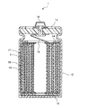
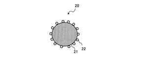
- FIG. 1 It is a schematic cross section of the nonaqueous electrolyte secondary battery which is an example of this embodiment. It is a schematic cross section of the positive electrode active material particle of this embodiment.
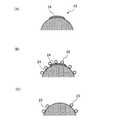
- (A) is a partial schematic cross-sectional view of a conventional lithium transition metal oxide particle containing a halogen atom
- (B) is a method of attaching a rare earth compound to the surface of a conventional lithium transition metal oxide particle containing a halogen atom.
- 2 is a partial schematic cross-sectional view of the positive electrode active material particles (conventional positive electrode active material particles)
- (C) is a partial schematic cross-sectional view showing the state of the conventional positive electrode active material particles during storage at high temperature. is there.
- (A) is a partial schematic cross-sectional view of a lithium transition metal oxide particle containing a halogen atom of this embodiment
- (B) is a rare earth on the surface of the lithium transition metal oxide particle containing a halogen atom of this embodiment. It is a partial schematic cross section of the positive electrode active material particle to which the compound was made to adhere.
- FIG. 1 is a cross-sectional view showing a nonaqueous electrolyte secondary battery which is an example of the present embodiment.
- the nonaqueous electrolyte secondary battery 1 includes a positive electrode 10, a negative electrode 11, and a nonaqueous electrolyte secondary battery separator 19 (hereinafter simply referred to as “separator”) interposed between the positive electrode 10 and the negative electrode 11. 19 ”) and a non-aqueous electrolyte (not shown).
- the positive electrode 10 and the negative electrode 11 are wound through a separator 19 and constitute a wound electrode group together with the separator 19.
- a cylindrical battery including a wound electrode group is illustrated, but application of the present disclosure is not limited thereto.
- the shape of the battery may be, for example, a square battery, a flat battery, a coin battery, a laminated film pack battery, or the like.
- the positive electrode 10 includes a positive electrode current collector such as a metal foil and a positive electrode active material layer formed on the positive electrode current collector.
- a positive electrode current collector such as a metal foil and a positive electrode active material layer formed on the positive electrode current collector.
- a metal foil that is stable in the potential range of the positive electrode such as aluminum, a film in which the metal is disposed on the surface layer, or the like can be used.
- the positive electrode active material layer preferably includes a positive electrode active material, and additionally includes a conductive material and a binder.
- FIG. 2 is a schematic cross-sectional view of the positive electrode active material particles of the present embodiment.
- the positive electrode active material particles 20 shown in FIG. 2 include lithium transition metal oxide particles 21 containing halogen atoms and rare earth compound particles 22 attached to the surfaces of the lithium transition metal oxide particles 21.
- halogen atoms are present inside the lithium transition metal oxide particles 21, and the amount of halogen atoms present on the surface of the lithium transition metal oxide particles 21 is included in the lithium transition metal oxide particles 21. It is 5 mass% or less of the total amount of halogen atoms.
- the rare earth elements constituting the rare earth compounds are rare earth elements excluding yttrium and scandium.
- the halogen atom present on the surface of the lithium transition metal oxide particle 21 means a halogen atom that is dispersed in water and eluted from the particle surface.
- B in the formula is the total amount of halogen atoms contained in the lithium transition metal oxide particles 21, and in the particles determined from the addition amount of the halogen compound that is a raw material of the lithium transition metal oxide containing halogen atoms.
- the amount of halogen atoms present on the surface of the lithium transition metal oxide particles 21 of the present embodiment may be 5% by mass or less of the total amount of halogen atoms contained in the lithium transition metal oxide particles 21, but the crystal structure stability From the viewpoint of properties and the like, the amount of halogen atoms present within a depth of 10 nm from the surface of the lithium transition metal oxide particles 21 is 5 mass% or less of the total amount of halogen atoms contained in the lithium transition metal oxide particles 21. Preferably there is.
- a lithium transition metal oxide containing a halogen atom is usually produced by firing a mixture containing raw material lithium oxide, transition metal oxide, halogen compound, etc., and solidifying the raw material. On the particle surface of the transition metal oxide, there are unreacted halogen compounds and by-products containing halogen atoms that are generated during solid solution. Therefore, in the conventional lithium transition metal oxide containing halogen atoms, the amount of halogen atoms present on the surface of the lithium transition metal oxide particles obtained from the above formula is 5% or more of the total amount of halogen atoms contained in the particles. Existing.
- the lithium transition metal oxide containing a halogen atom of the present embodiment is sufficiently washed with pure water, an acidic aqueous solution, or the like, for example, by calcination of the above raw material and solidification. Then, it is produced by removing unreacted halogen compounds and by-products containing halogen atoms present on the particle surface. Therefore, the amount of halogen atoms present on the surface of the lithium transition metal oxide particles containing halogen atoms is 5% by mass or less, preferably 1% by mass or less of the total amount of halogen atoms contained in the particles.
- FIG. 3A is a partial schematic cross-sectional view of a conventional lithium transition metal oxide particle containing a halogen atom
- FIG. 3B shows a rare earth on the surface of the conventional lithium transition metal oxide particle containing a halogen atom.
- FIG. 3 is a partial schematic cross-sectional view of a positive electrode active material particle (hereinafter referred to as a conventional positive electrode active material particle) to which a compound is attached
- FIG. 3 (C) shows a state of the conventional positive electrode active material particle during charge storage at a high temperature.
- the compound particles 24 containing halogen atoms have weak adhesion to the surface of the lithium transition metal oxide particles 23, the compound particles containing halogen atoms from the surface of the particles 23 due to expansion and contraction of the positive electrode active material accompanying charge / discharge of the battery. 24 peels off. Then, as shown in FIG. 3C, a surface (new surface) where the rare earth compound particles 25 do not exist is formed on the surface of the lithium transition metal oxide particles 23. Usually, the presence of the rare earth compound particles 25 forms a stable film with Li ion conductivity on the surface of the lithium transition metal oxide particles 23, and the decomposition of the nonaqueous electrolyte is suppressed by the film.
- the membrane that suppresses the decomposition of the non-aqueous electrolyte is not formed on the new surface, the decomposition of the non-aqueous electrolyte is promoted on the new surface during charge storage at high temperature, the capacity of the battery is reduced, and the non-aqueous electrolyte It is thought that gas generation is caused by the decomposition of.
- FIG. 4A is a partial schematic cross-sectional view of a lithium transition metal oxide particle containing a halogen atom of this embodiment
- FIG. 4B is a lithium transition metal oxide containing a halogen atom of this embodiment
- FIG. 3 is a partial schematic cross-sectional view of positive electrode active material particles in which a rare earth compound is adhered to the particle surface.
- the lithium transition metal oxide particle 21 of the present embodiment in which the amount of halogen atoms on the particle surface is 5% or less has almost all the compounds containing halogen atoms on the particle surface. Absent. Therefore, as shown in FIG.
- the positive electrode active material in which the rare earth compound particles 22 are attached to the surfaces of the lithium transition metal oxide particles 21 is caused by the expansion and contraction of the positive electrode active material accompanying the charging / discharging of the battery. It is considered that a surface (new surface) where the rare earth compound particles 22 do not exist is hardly formed. For this reason, even during storage at high temperatures, the presence of the rare earth compound particles 22 suppresses the decomposition of the nonaqueous electrolyte, so that it is considered that the capacity reduction of the battery and the generation of gas due to the decomposition of the nonaqueous electrolyte can also be suppressed.
- the lithium transition metal oxide particles 21 containing halogen atoms of the present embodiment since the halogen atoms are present inside the particles, the structure of the lithium transition metal oxide is stabilized, and the lithium transition metal oxide has a lithium content relative to the lithium transition metal oxide. Insertion and removal are performed smoothly. As a result, the charging voltage of the battery can be increased, and high energy density and high output can be achieved.
- the rare earth compound used in this embodiment is preferably at least one compound selected from rare earth hydroxides, oxyhydroxides, oxides, carbonic acid compounds, phosphoric acid compounds and fluorine compounds. Among these, at least one compound selected from rare earth hydroxides and oxyhydroxides is particularly preferable. When these rare earth compounds are used, decomposition of the nonaqueous electrolyte is further suppressed.
- the rare earth element constituting the rare earth compound is not particularly limited as long as it is a rare earth element other than yttrium and scandium.
- neodymium, samarium, erbium, and lanthanum are particularly preferable.
- Neodymium, samarium, erbium, and lanthanum compounds have higher adhesion to lithium transition metal oxide particles than other rare earth compounds, and the decomposition of the non-aqueous electrolyte during charge storage at high temperatures is further suppressed.
- yttrium and scandium compounds are less adherent to lithium transition metal oxide particles than other rare earth compounds, and the effect of suppressing decomposition of the nonaqueous electrolyte during charge storage at high temperatures cannot be sufficiently obtained. .
- rare earth compounds include neodymium hydroxide, neodymium oxyhydroxide, samarium hydroxide, samarium oxyhydroxide, erbium hydroxide, erbium oxyhydroxide, and other hydroxides and oxyhydroxides, as well as neodymium phosphate.
- the average particle diameter of the rare earth compound is preferably 1 nm or more and 100 nm or less, and more preferably 5 nm or more and 80 nm or less. If the average particle size of the rare earth compound exceeds 100 nm, the adhesion site of the lithium transition metal oxide to the particle surface may be biased, and the effect of suppressing decomposition of the nonaqueous electrolyte during charge storage at high temperatures is sufficiently obtained. It may not be possible. In addition, if the average particle size of the rare earth compound is less than 1 nm, the lithium transition metal oxide particle surface may be covered excessively, so that lithium insertion / extraction from the lithium transition metal oxide is not performed smoothly. There is a case.
- the average particle diameter in the present specification means a particle diameter (volume average particle diameter; Dv 50 ) at which the volume integrated value becomes 50% in the particle size distribution measured by the laser diffraction scattering method.
- Dv 50 can be measured, for example, using “LA-750” manufactured by HORIBA.
- the lithium transition metal oxide containing a halogen atom preferably has a concentration gradient in which the halogen atom concentration (mass%) increases from the surface of the particle toward the inside of the particle.
- the concentration gradient of halogen atoms is preferably formed in the range from the grain surface to a depth of 1 ⁇ m.
- concentration gradient of the halogen atom can be measured by EDX (energy dispersive X-ray analysis).
- the lithium cobalt-containing fluorinated oxide preferably contains the element A (Al, Ti, Zr, Ni, Mn) from the viewpoint of structural stability, but the composition ratio (c) of A is 0.25. If it exceeds, the energy density of the battery may decrease. Further, the lithium cobalt-containing fluorinated oxide preferably contains the element B (Mg, Ca) in terms of structural stability, but when the composition ratio (d) of the B exceeds 0.03, The energy density of the battery may decrease.
- composition ratio (f) of fluorine in the lithium cobalt-containing fluorinated oxide is less than 0.0005, the structural stability may be lowered. If it exceeds 0.0035, the energy density of the battery is lowered. There is a case.
- a lithium compound, a transition metal compound, and a halogen compound as raw materials are mixed at a molar ratio with respect to a Li atom so that the transition metal atom and the halogen atom are in a predetermined amount, and calcination is performed at a predetermined temperature.
- a transition metal and a solid solution containing halogen are obtained.
- a compound containing halogen atoms present on the particle surface of the solid solution is removed, and the amount of halogen atoms on the particle surface is 5% by mass or less.
- the lithium transition metal oxide of this embodiment is obtained.
- the pH of the aqueous solution used for washing is preferably in the range of 5 or more and less than 10. When the pH of the aqueous solution is less than 5, not only fluorine atoms existing on the particle surface of the solid solution but also fluorine atoms existing inside the particles may be removed.
- a method of forming a concentration gradient in which the halogen atom concentration (mass%) increases from the particle surface toward the inside of the particle is, for example, by using a halogen compound in an aqueous solution with controlled pH.
- the method of selectively removing is mentioned.
- the concentration gradient is formed by selectively removing LiF by using a weakly acidic aqueous solution.
- Examples of the raw material lithium compound include lithium hydroxide, lithium nitrate, lithium carbonate, and lithium chloride.
- Examples of the raw material transition metal compound include hydroxides, nitrates, carbonates, chloride salts of transition metals such as Co, Ni, and Mn.
- Examples of the halogen compound as a raw material include lithium salts such as fluorine, chlorine, bromine and iodine, magnesium salts, calcium salts and ammonium salts. From the viewpoint of the crystal structure stability of the lithium transition metal oxide, it is preferable to use lithium fluoride (LiF), magnesium fluoride (MgF 2 ), calcium fluoride (CaF 2 ) or the like as a raw material.
- the lithium transition metal oxide particles to which the rare earth compound is adhered are preferably heat-treated at, for example, 80 ° C. or more and 500 ° C. or less. If it is lower than 80 ° C., it may take an excessive amount of time to sufficiently dry the positive electrode active material obtained by the heat treatment. In addition, when the temperature exceeds 500 ° C., the rare earth hydroxide or oxyhydroxide becomes an oxide, but on the other hand, a part of the rare earth compound adhering to the surface diffuses inside the lithium transition metal oxide particles, There is a possibility that the effect of suppressing decomposition of the non-aqueous electrolyte is reduced.
- aqueous solution containing a rare earth compound a solution obtained by dissolving acetate, nitrate, sulfate, oxide or chloride in water or an organic solvent can be used. It is preferable to use one dissolved in water because of its high solubility.
- the positive electrode active material is not limited to the case where the above-described lithium transition metal oxide containing a halogen atom is used alone, and may be used by mixing with another positive electrode active material.
- the other positive electrode active material is not particularly limited as long as it is a compound that can reversibly insert and desorb lithium ions.
- cobalt that can insert and desorb lithium ions while maintaining a stable crystal structure.
- those having a layered structure such as lithium oxide and nickel cobalt lithium manganate, those having a spinel structure such as lithium manganese oxide and lithium nickel manganese oxide, and those having an olivine structure can be used.
- the lithium transition metal oxide containing a halogen atom of the present embodiment is preferably 50% by mass or more, and more preferably 80% by mass or more based on the total amount of the positive electrode active material.
- the positive electrode active materials may be of the same particle diameter or of different particle diameters. Also good.
- the conductive material is used to increase the electrical conductivity of the positive electrode active material layer.
- Examples of the conductive material include carbon materials such as carbon black, acetylene black, ketjen black, and graphite. These may be used alone or in combination of two or more.
- the binder is used to maintain a good contact state between the positive electrode active material and the conductive material and to enhance the binding property of the positive electrode active material and the like to the surface of the positive electrode current collector.
- the binder include polytetrafluoroethylene (PTFE), polyvinylidene fluoride (PVdF), and modified products thereof.
- PTFE polytetrafluoroethylene
- PVdF polyvinylidene fluoride
- the binder may be used in combination with a thickener such as carboxymethyl cellulose (CMC) or polyethylene oxide (PEO). These may be used alone or in combination of two or more.
- PTFE styrene-butadiene copolymer
- the binder may be used in combination with a thickener such as CMC.
- the negative electrode active material examples include a carbon material capable of inserting and extracting lithium, a metal capable of forming an alloy with lithium, or an alloy compound containing the metal.
- the carbon material natural graphite, non-graphitizable carbon, graphite such as artificial graphite, coke, etc. can be used, and examples of the alloy compound include those containing at least one metal capable of forming an alloy with lithium. It is done.
- silicon or tin is preferable as an element capable of forming an alloy with lithium, and silicon oxide, tin oxide, or the like in which these are combined with oxygen can also be used.
- what mixed the said carbon material and the compound of silicon or tin can be used.
- a negative electrode material having a higher charge / discharge potential than lithium carbon such as lithium titanate can be used.
- a porous sheet having ion permeability and insulating properties is used.
- the porous sheet include a microporous thin film, a woven fabric, and a nonwoven fabric.
- polyolefin such as polyethylene and polypropylene is suitable.
- the non-aqueous electrolyte includes a non-aqueous solvent and an electrolyte salt dissolved in the non-aqueous solvent.
- the electrolyte salt of the non-aqueous electrolyte include LiClO 4 , LiBF 4 , LiPF 6 , LiAlCl 4 , LiSbF 6 , LiSCN, LiCF 3 SO 3 , LiCF 3 CO 2 , LiAsF 6 , LiB 10 Cl 10 , and lower aliphatic carboxylic acid.
- Lithium, LiCl, LiBr, LiI, chloroborane lithium, borates, imide salts, and the like can be used.
- LiPF 6 is preferably used from the viewpoint of ion conductivity and electrochemical stability.
- One electrolyte salt may be used alone, or two or more electrolyte salts may be used in combination. These electrolyte salts are preferably contained at a ratio of 0.8 to 1.5 mol with respect to 1 L of the nonaqueous electrolyte.
- non-aqueous solvent for example, a cyclic carbonate, a chain carbonate, a cyclic carboxylic acid ester or the like is used.
- cyclic carbonate examples include propylene carbonate (PC), ethylene carbonate (EC), and fluoroethylene carbonate (FEC).
- chain carbonate examples include diethyl carbonate (DEC), ethyl methyl carbonate (EMC), and dimethyl carbonate (DMC).
- examples of the cyclic carboxylic acid ester include ⁇ -butyrolactone (GBL) and ⁇ -valerolactone (GVL).
- examples of the chain carboxylic acid ester examples include methyl propionate (MP) fluoromethyl propionate (FMP).
- a non-aqueous solvent may be used individually by 1 type, and may be used in combination of 2 or more type.
- Example 1 [Production of positive electrode]
- lithium carbonate (Li 2 CO 3 ) was used as a lithium source, and (Co 0.99 Al 0.01 ) 3 O 4 in which tricobalt tetroxide was compounded with Al as a cobalt source.
- This tricobalt tetroxide complexed with Al was obtained by precipitating cobalt and Al dissolved in an acid solution as a complex hydroxide and calcining at 300 ° C.
- the lithium carbonate and tricobalt tetroxide complexed with Al are weighed so that the molar ratio of Li / (Co + Al) is 1.05, and further fluorine for (Co + Al) of the positive electrode active material.
- LiF was added so that the amount of the element was 1.0 mol%, and these were mixed. Next, this mixture was fired in an air atmosphere to obtain a lithium cobalt-containing fluorinated oxide having a layered rock salt structure containing fluorine having an average particle size of 10 ⁇ m or less. Next, unreacted substances (LiF) or by-products (LiF, AlF, etc.) present on the particle surface of the lithium cobalt-containing fluorinated oxide were removed using an aqueous HCl solution adjusted to pH 6.
- the obtained positive electrode active material was observed with a scanning electron microscope (SEM), it was found that a rare earth compound having an average particle diameter of 1 nm or more and 100 nm or less was fixed on the surface of the positive electrode active material. . Further, when the amount of the rare earth compound fixed was measured by ICP, it was 0.068% by mass with respect to lithium cobaltate in terms of rare earth elements. Further, when the particle cross section of the positive electrode active material was measured by EDX, it was confirmed that the positive electrode active material had a concentration gradient in which the fluorine atom concentration increased in the range from the particle surface to the depth of about 1 ⁇ m.
- the fluorine atom by EDX was hardly detected in the depth exceeding 1 micrometer, it was estimated that the trace amount fluorine atom exists substantially uniformly. Further, when the positive electrode active material was dispersed in water and stirred for 1 hour, and the filtrate obtained by filtering the positive electrode active material was measured by ICP, the amount of fluorine atoms on the surface of the positive electrode active material was determined as positive electrode active material. The amount of fluorine atoms in the positive electrode active material particles was 95% by mass or less based on the total amount of fluorine atoms in the positive electrode active material particles.
- the positive electrode active material particles, carbon black (acetylene black) powder (average particle size: 40 nm) as a conductive agent, and polyvinylidene fluoride (PVdF) as a binder have a mass ratio of 95: 2.5: These were weighed to 2.5 and kneaded in an NMP solution to prepare a positive electrode mixture slurry.
- This positive electrode mixture slurry is applied to both sides of a positive electrode current collector made of aluminum foil, dried, and then rolled with a rolling roller to produce a positive electrode in which a positive electrode mixture layer is formed on both sides of the positive electrode current collector. did.
- the packing density of the positive electrode was 3.4 g / cc.
- Lithium hexafluorophosphate LiPF 6 was added to a mixed solvent in which ethylene carbonate (EC), methyl ethyl carbonate (MEC), and diethyl carbonate (DEC) were mixed at a volume ratio of 3: 5: 2.
- EC ethylene carbonate
- MEC methyl ethyl carbonate
- DEC diethyl carbonate
- a non-aqueous electrolyte was prepared by dissolving to a concentration of 0 mol / liter.
- a lead terminal is attached to each of the positive and negative electrodes, a separator is disposed between the two electrodes and wound in a spiral shape, and then a spiral electrode body is produced by pulling out the winding core.
- a flat electrode body was obtained.
- the flat electrode body and the non-aqueous electrolyte were inserted into an aluminum laminate outer package and sealed to prepare a battery.
- the design capacity of the battery (discharge capacity when charged to 4.40 V and discharged to 2.75 V) was 750 mAh.
- Example 2 A battery was fabricated in the same manner as in Example 1 except that the addition amount of LiF was changed from 1.0 mol% to 0.25 mol%.
- the amount of fluorine atoms on the surface of the positive electrode active material particles of Example 2 is 1% by mass or less with respect to the total amount of fluorine atoms in the positive electrode active material particles, and the amount of fluorine atoms inside the positive electrode active material particles is It was 99 mass% with respect to the total amount of fluorine atoms in the substance particles.
- Example 3 A battery was fabricated in the same manner as in Example 1 except that the addition amount of LiF was changed from 1.0 mol% to 5.0 mol%.
- the amount of fluorine atoms on the surface of the positive electrode active material particles of Example 3 is 5% by mass or less with respect to the total amount of fluorine atoms in the positive electrode active material particles, and the amount of fluorine atoms inside the positive electrode active material particles is It was 95 mass% with respect to the total amount of fluorine atoms in the substance particles.
- Example 4 A battery was fabricated in the same manner as in Example 1 except that the addition amount of LiF was changed from 1.0 mol% to 10.0 mol%.
- the amount of fluorine atoms on the surface of the positive electrode active material particles of Example 4 is 5% by mass or less with respect to the total amount of fluorine atoms in the positive electrode active material particles, and the amount of fluorine atoms inside the positive electrode active material particles is It was 95 mass% with respect to the total amount of fluorine atoms in the substance particles.
- the amount of fluorine atoms on the surface of the positive electrode active material particles of Comparative Example 2 is 70% by mass with respect to the total amount of fluorine atoms in the positive electrode active material particles, and the amount of fluorine atoms inside the positive electrode active material particles is the positive electrode active material It was 30 mass% with respect to the total amount of fluorine atoms in the particles.
- Example 3 A battery was fabricated in the same manner as in Example 1 except that the rare earth compound was not adhered to the particle surface of the positive electrode active material.
- the amount of fluorine atoms on the surface of the positive electrode active material particles in Comparative Example 3 is 5% by mass with respect to the total amount of fluorine atoms in the positive electrode active material particles, and the amount of fluorine atoms inside the positive electrode active material particles is the positive electrode active material. It was 95 mass% with respect to the total amount of fluorine atoms in the particles.
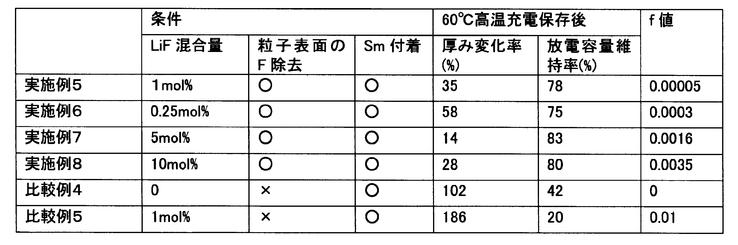
- Example 5 is the same as Example 1 except that a samarium compound is deposited instead of the erbium compound of Example 1, and Example 6 is the same as Example 2.
- Example 7 a battery was produced under the same conditions as in Example 3, and in Example 8 under the same conditions as in Example 4.
- the fluorine atomic weights of Examples 5 to 8 were the same as those of the corresponding Examples 1 to 4.
- Comparative Example 5 produced a battery in the same manner as in Example 5 except that LiF was not added.
- Comparative Example 5 was a battery in the same manner as in Example 5 except that fluorine on the particle surface was not removed. Was made.
- the amount of fluorine atoms in Comparative Example 5 was the same as in Comparative Example 2.
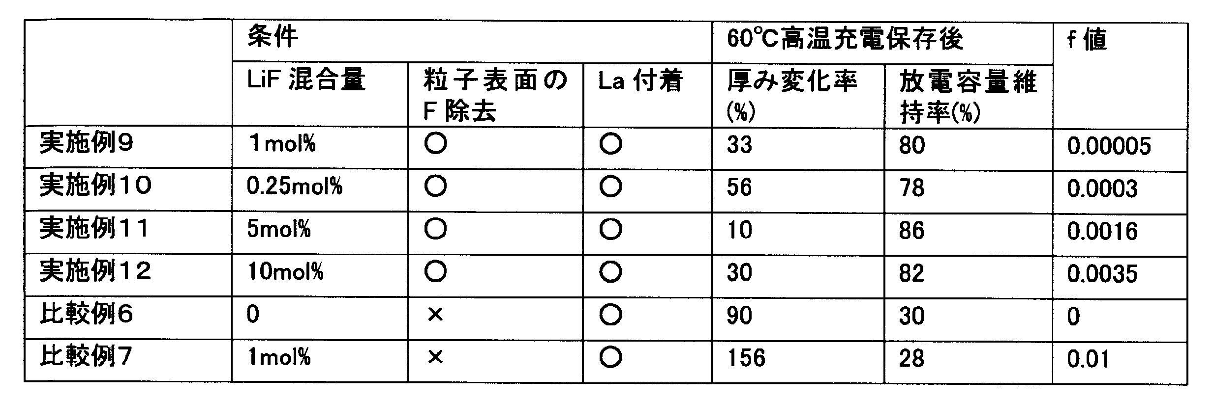
- Example 9 was performed under the same conditions as in Example 1 except that a lanthanum compound was deposited instead of the erbium compound in Example 1, and Example 10 was performed under the same conditions as in Example 2.
- Example 11 produced a battery under the same conditions as in Example 3 and Example 12 under the same conditions as in Example 4.
- the fluorine atomic weights of Examples 9 to 12 were the same as the corresponding Examples 1 to 4.
- Comparative Example 6 produced a battery as in Example 9 except that LiF was not added, and Comparative Example 7 was the same as in Example 9 except that fluorine on the particle surface was not removed. Was made.
- the amount of fluorine atoms in Comparative Example 7 was the same as that in Comparative Example 2.
- Example 13 is the same as Example 1 except that a neodymium compound is deposited instead of the erbium compound of Example 1, and Example 14 is the same as Example 2.
- Example 15 a battery was manufactured under the same conditions as in Example 3, and in Example 16 as in Example 4.
- the fluorine atomic weights of Examples 13 to 16 were the same as those of the corresponding Examples 1 to 4.
- Comparative Example 8 produced a battery similar to Example 13 except that LiF was not added, and Comparative Example 9 was a battery similar to Example 13 except that fluorine on the particle surface was not removed. Was made.
- the amount of fluorine atoms in Comparative Example 9 was the same as that in Comparative Example 2.
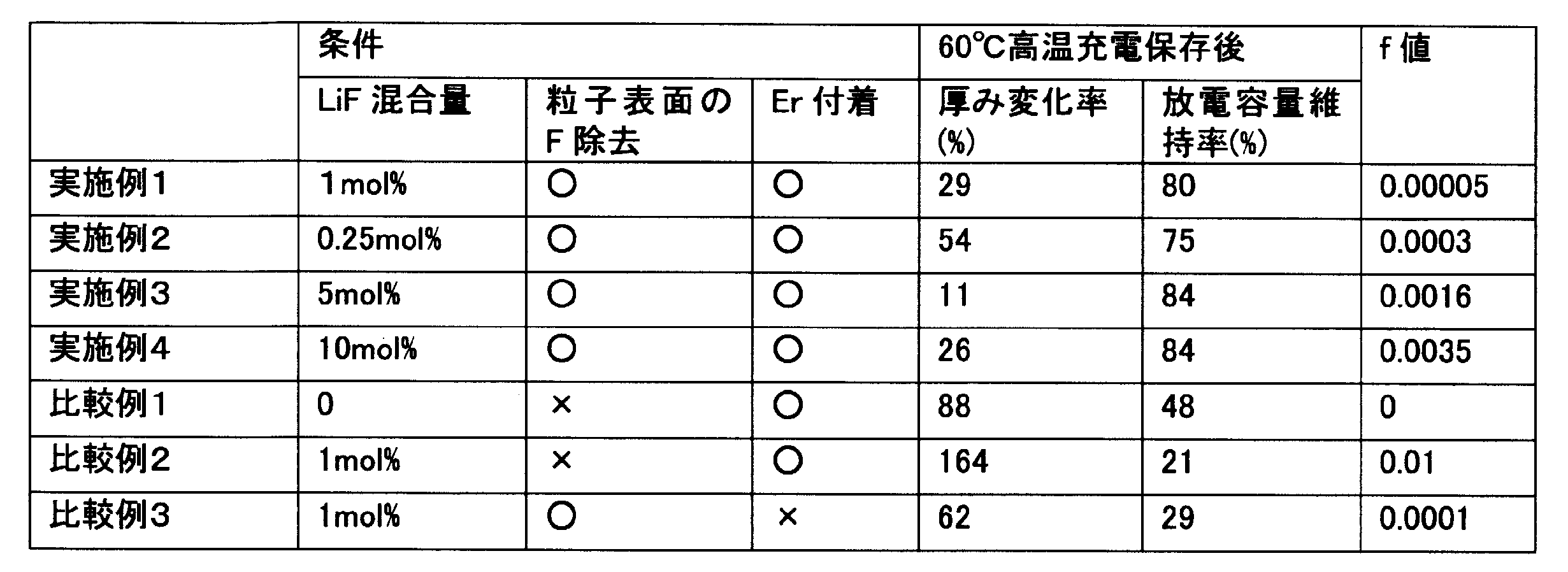
- Tables 1 to 4 summarize the results of the rate of change in thickness and the discharge capacity retention rate of the batteries of Examples 1 to 16 and Comparative Examples 1 to 9.
- the lower the rate of change in the thickness of the battery the lower the amount of gas generated by decomposition of the non-aqueous electrolyte in high temperature charge storage, and the higher the discharge capacity maintenance rate, the higher the charge storage at high temperature, It shows that the capacity reduction of the battery is low.
- Table 1 shows the composition ratio (f value) of fluorine in the positive electrode active materials of Examples and Comparative Examples.
- Examples 1 to 16 in which a rare earth compound was adhered to a lithium cobalt-containing fluorinated oxide in which the amount of fluorine atoms present on the particle surface was 5% by mass or less contained fluorine.
- nonaqueous electrolyte secondary battery 10 positive electrode, 11 negative electrode, 12 battery case, 13 sealing plate, 14 upper insulating plate, 15 lower insulating plate, 16 positive electrode lead, 17 negative electrode lead, 18 positive electrode terminal, 19 nonaqueous electrolyte secondary Battery separator, 20 positive electrode active material particles, 21, 23 lithium transition metal oxide particles, 22, 25 rare earth compound particles, 24 compound particles containing halogen atoms.
Landscapes
- Chemical & Material Sciences (AREA)
- Chemical Kinetics & Catalysis (AREA)
- Electrochemistry (AREA)
- General Chemical & Material Sciences (AREA)
- Inorganic Chemistry (AREA)
- Composite Materials (AREA)
- Battery Electrode And Active Subsutance (AREA)
Abstract
Description
正極10は、例えば金属箔等の正極集電体と、正極集電体上に形成された正極活物質層とで構成される。正極集電体には、アルミニウムなどの正極の電位範囲で安定な金属の箔、当該金属を表層に配置したフィルム等を用いることができる。正極活物質層は、正極活物質を含み、その他に、導電材及び結着材を含むことが好適である。
C(質量%)=A/B×100
ここで、式中のBは、リチウム遷移金属酸化物粒子21中に含まれるハロゲン原子の総量であり、ハロゲン原子を含むリチウム遷移金属酸化物の原料であるハロゲン化合物の添加量から求められる粒子中に理論上含有されたハロゲン原子の量である。なお、リチウム遷移金属酸化物粒子21の内部に存在するハロゲン原子の量(D)は、以下の式により求められる。
D(質量%)=100-(A/B×100)
負極11は、例えば金属箔等の負極集電体と、負極集電体上に形成された負極活物質層とを備える。負極集電体には、銅などの負極の電位範囲で安定な金属の箔、銅などの負極の電位範囲で安定な金属を表層に配置したフィルム等を用いることができる。負極活物質層は、リチウムイオンを吸蔵・脱離可能な負極活物質の他に、結着剤を含むことが好適である。結着剤としては、正極の場合と同様にPTFE等を用いることもできるが、スチレン-ブタジエン共重合体(SBR)又はこの変性体等を用いることが好ましい。結着剤は、CMC等の増粘剤と併用されてもよい。
セパレータ19には、イオン透過性及び絶縁性を有する多孔性シートが用いられる。多孔性シートの具体例としては、微多孔薄膜、織布、不織布等が挙げられる。セパレータの材質としては、ポリエチレン、ポリプロピレン等のポリオレフィンが好適である。
非水電解質は、非水溶媒と、非水溶媒に溶解した電解質塩とを含む。非水電解質の電解質塩としては、例えばLiClO4、LiBF4、LiPF6、LiAlCl4、LiSbF6、LiSCN、LiCF3SO3、LiCF3CO2、LiAsF6、LiB10Cl10、低級脂肪族カルボン酸リチウム、LiCl、LiBr、LiI、クロロボランリチウム、ホウ酸塩類、イミド塩類などを用いることができる。この中でも、イオン伝導性と電気化学的安定性の観点から、LiPF6を用いることが好ましい。電解質塩は、1種を単独で用いてもよく、2種以上を組み合わせて用いてもよい。これら電解質塩は、非水電解質1Lに対し0.8~1.5molの割合で含まれていることが好ましい。
[正極の作製]
出発原料として、リチウム源に炭酸リチウム(Li2CO3)を用い、コバルト源に四酸化三コバルトをAlで複合化した(Co0.99Al0.01)3O4を用いた。この四酸化三コバルトをAlで複合化したものは、酸溶液に溶解したコバルトとAlとを複合水酸化物として沈殿させ、300℃で仮焼することで得たものである。次に、上記炭酸リチウムと四酸化三コバルトをAlで複合化したものとを、Li/(Co+Al)のモル比が1.05になるように秤量後、更に正極活物質の(Co+Al)に対するフッ素元素の量が1.0mol%となるようにLiFを加えて、これらを混合した。次いで、この混合物を空気雰囲気下で焼成し、平均粒径10μm以下のフッ素を含む層状岩塩構造のリチウムコバルト含有フッ素化酸化物を得た。次に、リチウムコバルト含有フッ素化酸化物の粒子表面に存在する未反応物(LiF)、もしくは副生成物(LiF,AlF等)を、pH6に調整されたHCl水溶液を用いて除去した。
負極活物質の人造黒鉛と、分散剤としてのカルボキシメチルセルロースナトリウムと、結着剤としてのスチレン-ブタジエンゴムとを98:1:1の質量比で水溶液中において混合し、負極合剤スラリーを調製した。次に、この負極合剤スラリーを銅箔から成る負極集電体の両面に均一に塗布し、乾燥させ、圧延ローラにより圧延することにより、負極集電体の両面に負極合剤層が形成された負極を得た。この負極における負極活物質の充填密度は1.65g/cm3であった。
エチレンカーボネート(EC)とメチルエチルカーボネート(MEC)とジエチルカーボネート(DEC)とを、3:5:2の体積比で混合した混合溶媒に対し、六フッ化リン酸リチウム(LiPF6)を1.0モル/リットルの濃度になるように溶解させて、非水電
解液を調製した。
上記正負極それぞれにリード端子を取り付け、これら両極間にセパレータを配置して渦巻き状に巻回した後、巻き芯を引き抜いて渦巻状の電極体を作製し、更にこの電極体を押し潰して、扁平型の電極体を得た。次に、この扁平型の電極体と上記非水電解液とを、アルミニウムラミネート製の外装体内に挿入し、封止して電池を作製した。電池の設計容量(4.40Vまで充電し、2.75Vまで放電したときの放電容量)は750mAhであった。
LiFの添加量を1.0mol%から0.25mol%としたこと以外は、実施例1と同様に電池を作製した。実施例2の正極活物質の粒子表面のフッ素原子の量は正極活物質粒子中のフッ素原子の総量に対して1質量%以下であり、正極活物質の粒子内部のフッ素原子の量は正極活物質粒子中のフッ素原子の総量に対して99質量%であった。
LiFの添加量を1.0mol%から5.0mol%としたこと以外は、実施例1と同様に電池を作製した。実施例3の正極活物質の粒子表面のフッ素原子の量は正極活物質粒子中のフッ素原子の総量に対して5質量%以下であり、正極活物質の粒子内部のフッ素原子の量は正極活物質粒子中のフッ素原子の総量に対して95質量%であった。
LiFの添加量を1.0mol%から10.0mol%としたこと以外は、実施例1と同様に電池を作製した。実施例4の正極活物質の粒子表面のフッ素原子の量は正極活物質粒子中のフッ素原子の総量に対して5質量%以下であり、正極活物質の粒子内部のフッ素原子の量は正極活物質粒子中のフッ素原子の総量に対して95質量%であった。
LiFを添加しなかったこと以外は、実施例1と同様に電池を作製した。
フッ素を含む層状岩塩構造の正極活物質を得た後、上記正極活物質の粒子表面に存在する未反応物(LiF)、もしくは副生成物(LiF,AlF等)を除去することなく、上記正極活物質の粒子表面に希土類化合物を付着させたこと以外は、実施例1と同様に電池を作製した。比較例2の正極活物質の粒子表面のフッ素原子の量は正極活物質粒子中のフッ素原子の総量に対して70質量%であり、正極活物質の粒子内部のフッ素原子の量は正極活物質粒子中のフッ素原子の総量に対して30質量%であった。
正極活物質の粒子表面に希土類化合物を付着させなかったこと以外は、実施例1と同様に電池を作製した。比較例3の正極活物質の粒子表面のフッ素原子の量は正極活物質粒子中のフッ素原子の総量に対して5質量%であり、正極活物質の粒子内部のフッ素原子の量は正極活物質粒子中のフッ素原子の総量に対して95質量%であった。
実施例5~8は、実施例1のエルビウム化合物に代えてサマリウム化合物を付着させたこと以外、実施例5は実施例1と同様の条件で、実施例6は実施例2と同様の条件で、実施例7は実施例3と同様の条件で、実施例8は実施例4と同様の条件で、電池を作製した。実施例5~8のフッ素原子量は、対応する実施例1~4と同じであった。比較例5は、LiFを添加しなかったこと以外は実施例5と同様に電池を作成し、比較例5は、粒子表面のフッ素を除去しなかったこと以外は、実施例5と同様に電池を作製した。比較例5のフッ素原子量は、比較例2と同じであった。
実施例9~12は、実施例1のエルビウム化合物に代えてランタン化合物を付着させたこと以外、実施例9は実施例1と同様の条件で、実施例10は実施例2と同様の条件で、実施例11は実施例3と同様の条件で、実施例12は実施例4と同様の条件で、電池を作製した。実施例9~12のフッ素原子量は、対応する実施例1~4と同じであった。比較例6は、LiFを添加しなかったこと以外は実施例9と同様に電池を作成し、比較例7は、粒子表面のフッ素を除去しなかったこと以外は、実施例9と同様に電池を作製した。比較例7のフッ素原子量は、比較例2と同じであった。
実施例13~16は、実施例1のエルビウム化合物に代えてネオジム化合物を付着させたこと以外、実施例13は実施例1と同様の条件で、実施例14は実施例2と同様の条件で、実施例15は実施例3と同様の条件で、実施例16は実施例4と同様の条件で、電池を作製した。実施例13~16のフッ素原子量は、対応する実施例1~4と同じであった。比較例8は、LiFを添加しなかったこと以外は実施例13と同様に電池を作成し、比較例9は、粒子表面のフッ素を除去しなかったこと以外は、実施例13と同様に電池を作製した。比較例9のフッ素原子量は、比較例2と同じであった。
上記の各電池について、以下の条件のトリクル充電を行った。すなわち、60℃の環境下、1.0It(750mA)の電流で電池電圧が4.40Vとなるまで定電流充電を行
い、更に、4.40Vの電圧で65時間定電圧充電を行った。上記トリクル充電後の電池の厚み、及び放電容量を測定した。トリクル充電前と後の電池の厚みから電池の厚み変化率を求め、電池の初期容量とトリクル充電後の放電容量から放電容量維持率を求めた。

Claims (6)
- ハロゲン原子を含有するリチウム遷移金属酸化物と、前記リチウム遷移金属酸化物の粒子表面に付着した希土類化合物と、を含む正極活物質であって、
前記リチウム遷移金属酸化物の粒子表面に存在する、ハロゲン原子の量は、前記リチウム遷移金属酸化物の粒子に含有されたハロゲン原子総量の5質量%以下であり、
前記希土類化合物を構成する希土類元素は、イットリウム、スカンジウムを除く希土類元素である、正極活物質。 - 前記ハロゲン原子を含有するリチウム遷移金属酸化物は、フッ素原子を含有するリチウムコバルト酸化物を含む、請求項1記載の正極活物質。
- 前記ハロゲン原子を含有するリチウム遷移金属酸化物は、一般式LiaCobAcBdOeFf(Aは、Al,Ti,Zr,Ni,Mnから選ばれる少なくとも1種の元素を含み、BはMg,Caから選ばれる少なくとも1種の元素を含み、a=0.8~1.2、b=0.75~1.0、c=0~0.25、d=0~0.03、e=1.9~2.1、f=0.0005~0.0035)で表されるフッ素原子を含有するリチウムコバルト酸化物を含む、請求項1又は2記載の正極活物質。
- 前記ハロゲン原子を含有するリチウム遷移金属酸化物は、粒子表面から粒子内部に向ってハロゲン原子濃度が増加する濃度勾配を有する、請求項1~3のいずれか1項に記載の正極活物質。
- 前記ハロゲン原子の濃度勾配は、粒子表面から深さ1μmまでの範囲で形成されている、請求項4記載の正極活物質。
- 請求項1~5のいずれか1項に記載の正極活物質を含む正極を備える、非水電解質二次電池。
Priority Applications (3)
| Application Number | Priority Date | Filing Date | Title |
|---|---|---|---|
| CN201580060500.7A CN107112527B (zh) | 2014-12-25 | 2015-12-07 | 正极活性物质和非水电解质二次电池 |
| US15/520,032 US10559825B2 (en) | 2014-12-25 | 2015-12-07 | Positive electrode active material and nonaqueous electrolyte secondary battery |
| JP2016565888A JP6545711B2 (ja) | 2014-12-25 | 2015-12-07 | 正極活物質及び非水電解質二次電池 |
Applications Claiming Priority (2)
| Application Number | Priority Date | Filing Date | Title |
|---|---|---|---|
| JP2014263109 | 2014-12-25 | ||
| JP2014-263109 | 2014-12-25 |
Publications (1)
| Publication Number | Publication Date |
|---|---|
| WO2016103592A1 true WO2016103592A1 (ja) | 2016-06-30 |
Family
ID=56149663
Family Applications (1)
| Application Number | Title | Priority Date | Filing Date |
|---|---|---|---|
| PCT/JP2015/006059 Ceased WO2016103592A1 (ja) | 2014-12-25 | 2015-12-07 | 正極活物質及び非水電解質二次電池 |
Country Status (4)
| Country | Link |
|---|---|
| US (1) | US10559825B2 (ja) |
| JP (1) | JP6545711B2 (ja) |
| CN (1) | CN107112527B (ja) |
| WO (1) | WO2016103592A1 (ja) |
Cited By (1)
| Publication number | Priority date | Publication date | Assignee | Title |
|---|---|---|---|---|
| JPWO2019156161A1 (ja) * | 2018-02-09 | 2021-01-28 | 株式会社村田製作所 | リチウムイオン二次電池 |
Families Citing this family (4)
| Publication number | Priority date | Publication date | Assignee | Title |
|---|---|---|---|---|
| US11942632B2 (en) * | 2016-10-06 | 2024-03-26 | Lg Energy Solution, Ltd. | Positive electrode active material particle including core containing lithium cobalt oxide and shell containing composite metal oxide and preparation method thereof |
| JP6904892B2 (ja) * | 2017-11-28 | 2021-07-21 | トヨタ自動車株式会社 | 正極材料とこれを用いたリチウム二次電池 |
| JP6855427B2 (ja) * | 2018-10-15 | 2021-04-07 | 日本化学工業株式会社 | リチウム二次電池用正極活物質、その製造方法及びリチウム二次電池 |
| KR20260021974A (ko) * | 2024-08-07 | 2026-02-19 | 주식회사 엘 앤 에프 | 단일체 활물질 입자 및 이를 포함하는 리튬 이차전지 |
Citations (4)
| Publication number | Priority date | Publication date | Assignee | Title |
|---|---|---|---|---|
| JP2006351487A (ja) * | 2005-06-20 | 2006-12-28 | Sony Corp | 正極活物質およびその製造方法、並びに電池 |
| JP4217712B2 (ja) * | 2003-09-16 | 2009-02-04 | Agcセイミケミカル株式会社 | リチウム−ニッケル−コバルト−マンガン−フッ素含有複合酸化物ならびにその製造方法およびそれを用いたリチウム二次電池 |
| WO2014049958A1 (ja) * | 2012-09-28 | 2014-04-03 | 三洋電機株式会社 | 非水電解質二次電池用正極活物質及びその正極活物質を用いた非水電解質二次電池 |
| WO2014156024A1 (ja) * | 2013-03-27 | 2014-10-02 | 三洋電機株式会社 | 非水電解質二次電池 |
Family Cites Families (12)
| Publication number | Priority date | Publication date | Assignee | Title |
|---|---|---|---|---|
| JP3112138B2 (ja) | 1993-07-20 | 2000-11-27 | セントラル硝子株式会社 | 含リチウム金属ハロゲン化酸化物およびその製造法 |
| JP3959333B2 (ja) | 2001-11-20 | 2007-08-15 | 日本化学工業株式会社 | リチウムコバルト系複合酸化物、その製造方法、リチウム二次電池正極活物質及びリチウム二次電池 |
| JP2005225734A (ja) | 2004-02-16 | 2005-08-25 | Nippon Chem Ind Co Ltd | フッ素含有リチウムコバルト系複合酸化物及びその製造方法 |
| CN100438154C (zh) * | 2004-04-30 | 2008-11-26 | 清美化学股份有限公司 | 锂二次电池正极用含锂复合氧化物的制造方法 |
| KR100995255B1 (ko) * | 2004-07-20 | 2010-11-19 | 에이지씨 세이미 케미칼 가부시키가이샤 | 리튬 2 차 전지용 정극 활물질 및 그 제조 방법 |
| JP4649379B2 (ja) * | 2006-07-31 | 2011-03-09 | 株式会社東芝 | 燃料電池用電極、膜電極複合体および燃料電池、ならびにそれらの製造法 |
| JP4715830B2 (ja) | 2007-10-19 | 2011-07-06 | ソニー株式会社 | 正極活物質、正極および非水電解質二次電池 |
| CN101785134B (zh) * | 2008-06-26 | 2013-01-16 | Agc清美化学股份有限公司 | 锂离子二次电池的正极活性物质用表面修饰含锂复合氧化物及其制造方法 |
| JP5675113B2 (ja) * | 2010-01-06 | 2015-02-25 | 三洋電機株式会社 | 非水電解質二次電池及び非水電解質二次電池用正極 |
| JP5717133B2 (ja) * | 2010-06-28 | 2015-05-13 | 三洋電機株式会社 | 非水電解質二次電池用正極活物質、その正極活物質の製造方法、当該正極活物質を用いた正極、及びその正極を用いた電池 |
| CN103022467B (zh) * | 2011-09-28 | 2018-01-05 | 北京当升材料科技股份有限公司 | 一种表面处理的锰酸锂材料及其制备方法 |
| US20150022194A1 (en) * | 2013-07-18 | 2015-01-22 | Blackberry Limited | Magnetometer for aligning a portable device on a planar charging surface of an inductive charging unit |
-
2015
- 2015-12-07 WO PCT/JP2015/006059 patent/WO2016103592A1/ja not_active Ceased
- 2015-12-07 CN CN201580060500.7A patent/CN107112527B/zh active Active
- 2015-12-07 JP JP2016565888A patent/JP6545711B2/ja active Active
- 2015-12-07 US US15/520,032 patent/US10559825B2/en active Active
Patent Citations (4)
| Publication number | Priority date | Publication date | Assignee | Title |
|---|---|---|---|---|
| JP4217712B2 (ja) * | 2003-09-16 | 2009-02-04 | Agcセイミケミカル株式会社 | リチウム−ニッケル−コバルト−マンガン−フッ素含有複合酸化物ならびにその製造方法およびそれを用いたリチウム二次電池 |
| JP2006351487A (ja) * | 2005-06-20 | 2006-12-28 | Sony Corp | 正極活物質およびその製造方法、並びに電池 |
| WO2014049958A1 (ja) * | 2012-09-28 | 2014-04-03 | 三洋電機株式会社 | 非水電解質二次電池用正極活物質及びその正極活物質を用いた非水電解質二次電池 |
| WO2014156024A1 (ja) * | 2013-03-27 | 2014-10-02 | 三洋電機株式会社 | 非水電解質二次電池 |
Cited By (1)
| Publication number | Priority date | Publication date | Assignee | Title |
|---|---|---|---|---|
| JPWO2019156161A1 (ja) * | 2018-02-09 | 2021-01-28 | 株式会社村田製作所 | リチウムイオン二次電池 |
Also Published As
| Publication number | Publication date |
|---|---|
| CN107112527B (zh) | 2020-03-03 |
| US20170324093A1 (en) | 2017-11-09 |
| US10559825B2 (en) | 2020-02-11 |
| JPWO2016103592A1 (ja) | 2017-10-05 |
| CN107112527A (zh) | 2017-08-29 |
| JP6545711B2 (ja) | 2019-07-17 |
Similar Documents
| Publication | Publication Date | Title |
|---|---|---|
| KR102140969B1 (ko) | 비수 전해질 이차전지용 양극 활물질, 그 제조 방법 및 그것을 이용한 비수 전해질 이차전지 | |
| JP6117117B2 (ja) | 非水電解質二次電池の正極及び非水電解質二次電池 | |
| JP6443441B2 (ja) | 非水電解質二次電池用正極活物質及び非水電解質二次電池用正極 | |
| JP5528564B2 (ja) | 非水電解質二次電池 | |
| JP6493406B2 (ja) | 非水電解質二次電池用正極活物質 | |
| JPWO2012099265A1 (ja) | 非水電解質二次電池用正極活物質、その正極活物質を用いた非水電解質二次電池用正極及びその正極を用いた非水電解質二次電池 | |
| US20180248186A1 (en) | Positive electrode active material for nonaqueous electrolyte secondary batteries, production method thereof, and nonaqueous electrolyte secondary battery | |
| WO2016017093A1 (ja) | 非水電解質二次電池用正極活物質 | |
| WO2015125444A1 (ja) | 非水電解質二次電池用正極活物質 | |
| JP5036121B2 (ja) | 非水電解質二次電池 | |
| WO2014155988A1 (ja) | 非水電解質二次電池用正極活物質及びこれを用いた非水電解質二次電池 | |
| JP2005340056A (ja) | 非水電解質二次電池 | |
| JP6522661B2 (ja) | 非水電解質二次電池用正極活物質及び非水電解質二次電池 | |
| JP6545711B2 (ja) | 正極活物質及び非水電解質二次電池 | |
| JPWO2018150843A1 (ja) | 非水電解質二次電池 | |
| CN107004897B (zh) | 非水电解质二次电池 | |
| JP2004281158A (ja) | 非水電解質二次電池 | |
| JP2005142004A (ja) | 非水電解質二次電池 | |
| JP2010177207A (ja) | 非水電解質二次電池 | |
| CN109478644B (zh) | 非水电解质二次电池用正极、正极活性物质及其制造方法、及非水电解质二次电池 | |
| CN107836056B (zh) | 非水电解质二次电池 |
Legal Events
| Date | Code | Title | Description |
|---|---|---|---|
| 121 | Ep: the epo has been informed by wipo that ep was designated in this application |
Ref document number: 15872169 Country of ref document: EP Kind code of ref document: A1 |
|
| ENP | Entry into the national phase |
Ref document number: 2016565888 Country of ref document: JP Kind code of ref document: A |
|
| WWE | Wipo information: entry into national phase |
Ref document number: 15520032 Country of ref document: US |
|
| NENP | Non-entry into the national phase |
Ref country code: DE |
|
| 122 | Ep: pct application non-entry in european phase |
Ref document number: 15872169 Country of ref document: EP Kind code of ref document: A1 |