WO2016092772A1 - 内燃機関の可変バルブタイミング制御装置 - Google Patents
内燃機関の可変バルブタイミング制御装置 Download PDFInfo
- Publication number
- WO2016092772A1 WO2016092772A1 PCT/JP2015/005964 JP2015005964W WO2016092772A1 WO 2016092772 A1 WO2016092772 A1 WO 2016092772A1 JP 2015005964 W JP2015005964 W JP 2015005964W WO 2016092772 A1 WO2016092772 A1 WO 2016092772A1
- Authority
- WO
- WIPO (PCT)
- Prior art keywords
- angle signal
- cam angle
- timing
- crank angle
- phase
- Prior art date
- Legal status (The legal status is an assumption and is not a legal conclusion. Google has not performed a legal analysis and makes no representation as to the accuracy of the status listed.)
- Ceased
Links
Images



Classifications
-
- F—MECHANICAL ENGINEERING; LIGHTING; HEATING; WEAPONS; BLASTING
- F02—COMBUSTION ENGINES; HOT-GAS OR COMBUSTION-PRODUCT ENGINE PLANTS
- F02D—CONTROLLING COMBUSTION ENGINES
- F02D13/00—Controlling the engine output power by varying inlet or exhaust valve operating characteristics, e.g. timing
- F02D13/02—Controlling the engine output power by varying inlet or exhaust valve operating characteristics, e.g. timing during engine operation
-
- Y—GENERAL TAGGING OF NEW TECHNOLOGICAL DEVELOPMENTS; GENERAL TAGGING OF CROSS-SECTIONAL TECHNOLOGIES SPANNING OVER SEVERAL SECTIONS OF THE IPC; TECHNICAL SUBJECTS COVERED BY FORMER USPC CROSS-REFERENCE ART COLLECTIONS [XRACs] AND DIGESTS
- Y02—TECHNOLOGIES OR APPLICATIONS FOR MITIGATION OR ADAPTATION AGAINST CLIMATE CHANGE
- Y02T—CLIMATE CHANGE MITIGATION TECHNOLOGIES RELATED TO TRANSPORTATION
- Y02T10/00—Road transport of goods or passengers
- Y02T10/10—Internal combustion engine [ICE] based vehicles
- Y02T10/12—Improving ICE efficiencies
Definitions
- the present disclosure relates to a variable valve timing control device for an internal combustion engine.
- valve timing of an intake valve or an exhaust valve is changed by changing the rotation phase (VCT phase) of the camshaft with respect to the crankshaft of the internal combustion engine for the purpose of improving output, reducing fuel consumption, and reducing emissions.
- VCT phase rotation phase
- Some are equipped with a variable valve timing device that changes (open / close timing).
- Patent Document 1 discloses a system including a variable valve timing device.
- the actual VCT phase is calculated based on the crank angle signal output from the crank angle sensor in synchronization with the rotation of the crankshaft and the cam angle signal output from the cam angle sensor in synchronization with the rotation of the camshaft.
- the variable valve timing device is controlled so that the actual VCT phase (actual valve timing) matches the target VCT phase (target valve timing).
- variable valve timing device In recent years, with the electrification of the variable valve timing device, it has become necessary to perform VCT phase control (valve timing control) even during the stop of the internal combustion engine (the period during which the rotation of the internal combustion engine stops). It is coming.
- VCT phase control valve timing control
- Patent Document 1 does not disclose a technique for calculating an actual VCT phase while the internal combustion engine is stopped.
- the actual VCT phase can be accurately calculated even if reverse rotation occurs during the stop of the internal combustion engine, and the control accuracy of the VCT phase during the stop of the internal combustion engine can be ensured.
- An object is to provide a valve timing control device.
- a variable valve timing device that changes a valve timing by changing a VCT phase that is a rotation phase of a camshaft with respect to a crankshaft, and a crank angle that outputs a crank angle signal in synchronization with the rotation of the crankshaft
- a variable valve timing control device for an internal combustion engine that includes a sensor and a cam angle sensor that outputs a cam angle signal in synchronization with the rotation of the camshaft.
- a phase calculation unit for calculating an actual VCT phase based on the angle signal is provided. The phase calculation unit is configured so that the crank angle signal used for calculating the actual VCT phase is opposite to the input timing of the specific cam angle signal used for calculating the actual VCT phase when the internal combustion engine is rotating forward and backward. Switch to the crank angle signal at the crank angle position.
- the crank angle signal used for the calculation of the actual VCT phase is corresponding to the fact that the generation order of the cam angle signal and the crank angle signal is reversed when the internal combustion engine rotates reversely. It is possible to switch to a crank angle signal at a crank angle position on the opposite side to the forward rotation with respect to the input timing of a specific cam angle signal used for calculating the VCT phase. As a result, even if reverse rotation occurs during the stoppage of the internal combustion engine (period in which the rotation of the internal combustion engine stops), the generation order of the cam angle signal and the crank angle signal used for calculating the actual VCT phase is set to the normal rotation time. Thus, the actual VCT phase can be calculated with high accuracy and the control accuracy of the VCT phase during the stoppage of the internal combustion engine can be ensured.
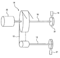
- FIG. 1 is a diagram illustrating a schematic configuration of a valve timing control system according to the first embodiment.
- FIG. 2 is a schematic configuration diagram of the variable valve timing device and its peripheral part.
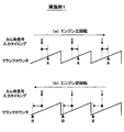
- FIG. 3 is a diagram for explaining a method of calculating the VCT phase during forward rotation and reverse rotation of the engine according to the first embodiment.
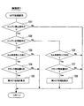
- FIG. 4 is a flowchart showing the flow of processing of the VCT phase calculation routine of the first embodiment.
- FIG. 5 is a diagram for explaining a method of calculating the VCT phase during forward and reverse rotation of the engine according to the second embodiment.
- FIG. 6 is a flowchart showing the flow of processing of the VCT phase calculation routine of the second embodiment.
- FIG. 7 is a diagram for explaining a method of calculating the VCT phase during forward rotation and reverse rotation of the engine according to the third embodiment.
- FIG. 8 is a flowchart showing the flow of processing of the VCT phase calculation routine of the third embodiment.
- FIG. 9 is a diagram for explaining a method of calculating the VCT phase at the time of forward rotation and reverse rotation of the engine according to the fourth embodiment.
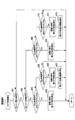
- FIG. 10 is a flowchart illustrating a process flow of the VCT phase calculation routine according to the fourth embodiment.
- Example 1 A first embodiment will be described with reference to FIGS. First, a schematic configuration of the entire system will be described with reference to FIGS. 1 and 2.
- the power from a crankshaft 12 is supplied to an intake side camshaft 16 and an exhaust side camshaft 17 via sprockets 14 and 15 by a timing chain 13 (or timing belt).
- the intake side camshaft 16 is provided with an electric variable valve timing device 18.
- the variable valve timing device 18 changes the rotational phase of the intake side camshaft 16 with respect to the crankshaft 12 (hereinafter referred to as “VCT phase”), whereby an intake valve (not shown) that is driven to open and close by the intake side camshaft 16. ) Valve timing (opening / closing timing) is changed.
- a cam angle sensor 19 that outputs a cam angle signal for each predetermined cam angle in synchronization with the rotation of the intake side cam shaft 16 is provided on the outer peripheral side of the intake side cam shaft 16. Is attached.
- a crank angle sensor 21 that outputs a crank angle signal at every predetermined crank angle in synchronization with the rotation of the crankshaft 12 is attached to the outer peripheral side of the crankshaft 12.
- the crank angle sensor 21 is a crank angle sensor with a reverse rotation detection function that outputs different crank angle signals (for example, crank angle signals having different pulse widths) when the crankshaft 12 rotates forward and backward.
- variable valve timing device 18 uses a motor 22 (for example, a brush motor) as a driving source to change the VCT phase (the rotational phase of the intake camshaft 16 with respect to the crankshaft 12) to change the valve timing. It is configured to change.
- a motor 22 for example, a brush motor
- the outputs of the various sensors described above are input to an electronic control unit (hereinafter referred to as “ECU”) 30.
- the ECU 30 is mainly composed of a microcomputer, and executes various engine control programs stored in a built-in ROM (storage medium), so that the fuel injection amount and the ignition timing are determined according to the engine operating state.
- the throttle opening (intake air amount) and the like are controlled.
- the ECU 30 calculates the target VCT phase based on the engine operating state and the like, calculates the actual VCT phase based on the crank angle signal and the cam angle signal, and sets the actual VCT phase (actual valve timing) to the target VCT phase ( VCT phase control for feedback control of the motor 22 of the variable valve timing device 18 is performed so as to match the target valve timing.
- VCT phase control valve timing control
- the engine 11 may reversely rotate without exceeding the compression top dead center just before the rotation stops.
- the generation order of the cam angle signal and the crank angle signal is reversed from that at the time of normal rotation.
- the actual VCT phase is calculated based on the cam angle signal and the crank angle signal while the engine 11 is stopped by executing the VCT phase calculation routine of FIG.
- the crank angle signal used for calculating the actual VCT phase during the forward rotation and the reverse rotation of the engine 11 is changed to a crank that is opposite to the input timing of the specific cam angle signal used for calculating the actual VCT phase.
- the crank angle signal at the angular position (crank timing) is switched.
- the actual VCT phase is calculated based on the phase difference between the specific cam angle signal and the crank angle signal at the crank angle position A on the advance side.
- the actual VCT phase is calculated based on the phase difference between the specific cam angle signal and the crank angle signal at the crank angle position B on the retard side.
- the crank angle signal used to calculate the actual VCT phase corresponds to the fact that the generation order of the cam angle signal and crank angle signal is reversed from that in the normal rotation. It is possible to switch to a crank angle signal at a crank angle position on the opposite side to the forward rotation with respect to the input timing of a specific cam angle signal used for calculating the VCT phase. As a result, even if reverse rotation occurs while the engine 11 is stopped, the generation order of the cam angle signal and crank angle signal used to calculate the actual VCT phase is set to the same order as in the normal rotation, and the actual VCT phase is set. Can be calculated with high accuracy.
- the VCT phase calculation routine shown in FIG. 4 is repeatedly executed at a predetermined cycle during the power-on period of the ECU 30, and corresponds to a phase calculation unit.
- step 101 it is determined whether or not the engine 11 is being stopped (the period during which the rotation of the engine 11 stops), for example, whether or not the combustion of the engine 11 has stopped. If it is determined by this, and it is determined that the engine 11 is not in the middle of stopping, this routine is terminated without executing the processing from step 102 onward.
- step 101 determines whether the engine 11 is rotating forward based on the crank angle signal of the crank angle sensor 21. .
- step 102 If it is determined in step 102 that the engine 11 is rotating forward, the process proceeds to step 103, where it is determined whether or not a specific cam angle signal is input, and if a specific cam angle signal is not input. If it is determined, this routine is terminated.
- step 104 when it is determined in step 104 that the crank angle position A on the advance side has been reached (that is, the input timing of the crank angle signal of the crank angle position A on the advance side), the process proceeds to step 105, where The actual VCT phase is calculated based on the phase difference between the cam angle signal and the crank angle signal at the crank angle position A on the advance side.
- step 102 determines whether the engine 11 is rotating forward (that is, the engine 11 is rotating backward). If it is determined that a specific cam angle signal has not been input, this routine ends.
- step 107 when it is determined in step 107 that the retarded crank angle position B has been reached (that is, the input timing of the crank angle signal at the retarded crank angle position B), the process proceeds to step 108 and a specific The actual VCT phase is calculated based on the phase difference between the cam angle signal and the crank angle signal at the retarded crank angle position B.
- the actual VCT phase is calculated based on the cam angle signal and the crank angle signal while the engine 11 is stopped (during the process in which the rotation of the engine 11 stops). At that time, during the forward rotation of the engine 11, the specific cam angle signal and the crank angle position A on the advance side are inputted at the input timing of the crank angle signal on the advance crank angle position A after the input of the specific cam angle signal.
- the actual VCT phase is calculated based on the phase difference from the crank angle signal.
- the ECU 30 executes a VCT phase calculation routine shown in FIG. 6 to be described later, so that the actual VCT phase is calculated as follows based on the cam angle signal and the crank angle signal while the engine 11 is stopped. To do.
- crank angle position D crank counter
- step 201 it is determined whether or not the engine 11 is in the middle of stopping. If it is determined that the engine 11 is not in the middle of stopping, the processing in and after step 202 is performed. This routine is terminated without executing.
- step 201 determines whether or not the engine 11 is rotating forward based on the crank angle signal.
- step 203 the process proceeds to step 204, where it is determined whether a specific cam angle signal has been input, and a specific cam angle is determined. If it is determined that no signal is input, this routine ends.
- step 204 when it is determined in step 204 that a specific cam angle signal is input (that is, the input timing of the specific cam angle signal), the process proceeds to step 205 and the crank angle signal of the crank angle position C on the retarded side is reached.
- the actual VCT phase is calculated based on the phase difference between the specific cam angle signal and the specific cam angle signal.
- step 206 the process proceeds to step 207, where it is determined whether a specific cam angle signal has been input, and a specific cam angle is determined. If it is determined that no signal is input, this routine ends.
- step 207 when it is determined in step 207 that the specific cam angle signal is input (that is, the input timing of the specific cam angle signal), the process proceeds to step 208 and the crank angle signal of the crank angle position D on the advance side is reached.
- the actual VCT phase is calculated based on the phase difference between the specific cam angle signal and the specific cam angle signal.
- the crank angle signal of the crank angle position C on the retard side before the input of the specific cam angle signal is specified.
- the actual VCT phase is calculated based on the phase difference from the cam angle signal.
- the position of the crank angle signal at the crank angle position D on the advance side before the input of the specific cam angle signal and the specific cam angle signal is calculated.
- An actual VCT phase is calculated based on the phase difference. In this way, in both the forward rotation and the reverse rotation of the engine 11, the specific cam angle signal and the input timing before the specific cam angle signal are input at the input timing of the specific cam angle signal.
- Example 3 Embodiment 3 will be described with reference to FIGS. However, description of substantially the same parts as those in the first embodiment will be omitted or simplified, and different parts from the first embodiment will be mainly described.
- the system provided with the variable valve timing device 18 has a characteristic that the VCT phase fluctuates due to the fluctuation of the cam torque acting on the cam shaft 16.
- the cam angle sensor 19 has a timing (for example, with respect to the fluctuation center) at which the fluctuation of the VCT phase becomes small when the engine 11 rotates forward.
- the cam angle signal is set to rise at the timing when the absolute value of the fluctuation amount is minimized. That is, teeth are provided on the outer periphery of the cam rotor 31 (see FIG. 2) so that the cam angle signal of the cam angle sensor 19 rises at the timing when the fluctuation of the VCT phase becomes small.
- the rising timing and the falling timing of the cam angle signal are reversed between the forward rotation and the reverse rotation of the engine 11. become. Therefore, if the cam angle signal rising timing is the cam angle signal input timing regardless of whether the rotation is forward or reverse, the cam angle signal input timing during reverse rotation is equal to the cam angle signal input timing during forward rotation (VCT). The timing of the actual VCT phase during the stoppage of the engine 11 may be reduced.
- the input timing of the cam angle signal is as follows. To set.
- step 301 it is determined whether or not the engine 11 is being stopped. If it is determined that the engine 11 is not being stopped, the processing after step 302 is performed. This routine is terminated without executing.
- step 301 if it is determined in step 301 that the engine 11 is being stopped, the process proceeds to step 302, where it is determined whether the engine 11 is rotating forward based on the crank angle signal.
- step 302 If it is determined in step 302 that the engine 11 is rotating forward, the process proceeds to step 303, where it is determined whether or not it is the rising timing of the cam angle signal, and it is determined that it is not the rising timing of the cam angle signal. If this is the case, this routine ends.
- step 303 when it is determined in step 303 that the cam angle signal rises, it is determined that the cam angle signal is input (timing at which the variation in the VCT phase is small), and the process proceeds to step 304 where the crank angle signal and Based on the phase difference from the cam angle signal, the actual VCT phase when the fluctuation is small is calculated.
- the actual VCT phase when the fluctuation is small based on the phase difference between the crank angle signal input timing at the retarded crank angle position before the cam angle signal input and the cam angle signal input timing (rise timing). Is calculated.
- step 302 determines whether or not the engine 11 is rotating forward (that is, the engine 11 is rotating backward)
- the routine proceeds to step 305, where is the falling timing of the cam angle signal? This routine is finished when it is determined whether or not it is not the falling timing of the cam angle signal.
- the cam angle signal input timing (timing at which the variation in the VCT phase becomes small) is determined.
- the actual VCT phase when the fluctuation is small is calculated based on the phase difference between the cam angle signal and the cam angle signal. In this case, for example, the actual VCT when the fluctuation is small based on the phase difference between the crank angle signal input timing at the advanced crank angle position before the cam angle signal input and the cam angle signal input timing (falling timing). Calculate the phase.
- the cam angle signal rise timing is used as the cam angle signal input timing when the engine 11 is rotating forward
- the cam angle signal fall timing is used as the cam angle signal when the engine 11 is rotating backward.
- the actual VCT phase is calculated as the input timing.
- the input timing of the cam angle signal at the time of reverse rotation is changed to the input timing of the cam angle signal at the time of forward rotation (VCT phase fluctuation). The timing at which the actual VCT phase is calculated during the stop of the engine 11 can be improved.
- the cam angle signal is set to rise at the timing when the fluctuation of the VCT phase becomes small during the forward rotation of the engine 11, but the present invention is not limited to this, and the fluctuation of the VCT phase when the engine 11 rotates forward.
- the cam angle signal may be set to fall at a timing when becomes smaller.
- the falling timing of the cam angle signal is the input timing of the cam angle signal when the engine 11 is rotating forward
- the rising timing of the cam angle signal is the input timing of the cam angle signal when the engine 11 is rotating backward.
- Example 4 Embodiment 4 will be described with reference to FIGS. 9 and 10. However, description of substantially the same parts as those in the first embodiment will be omitted or simplified, and different parts from the first embodiment will be mainly described.
- the cam angle sensor 19 rises at a timing when the fluctuation of the VCT phase becomes small and the fluctuation of the VCT phase becomes large when the engine 11 rotates forward.
- the cam angle signal is set to fall at a certain timing (for example, a timing at which the absolute value of the fluctuation amount with respect to the fluctuation center becomes maximum).
- the cam rotor 31 (FIG. 2) is configured so that the cam angle signal of the cam angle sensor 19 rises at the timing when the fluctuation of the VCT phase becomes small and the cam angle signal of the cam angle sensor 19 falls at the timing when the fluctuation of the VCT phase becomes large. Teeth) are provided on the outer periphery of the reference. Therefore, as shown in FIG. 9B, when the engine 11 rotates in the reverse direction, the cam angle sensor 19 falls at the timing when the cam angle signal falls at the timing when the variation in the VCT phase becomes small and the variation at the VCT phase becomes large. The cam angle signal will rise.
- the ECU 30 executes a VCT phase calculation routine of FIG. 10 to be described later, so that the actual VCT phase and the amplitude (variation) of the actual VCT phase are as follows while the engine 11 is stopped. calculate.
- the cam angle signal rises (that is, the timing at which the fluctuation of the VCT phase becomes small) based on the phase difference between the cam angle signal and the crank angle signal.
- the actual VCT phase when the fluctuation is small is calculated.
- the actual VCT phase at the time of large variation is calculated based on the phase difference between the cam angle signal and the crank angle signal.
- the difference between the actual VCT phase at the time and the actual VCT phase when the fluctuation is small is calculated as the amplitude of the actual VCT phase.
- the phase difference between the cam angle signal and the crank angle signal at the falling timing of the cam angle signal (that is, the timing at which the fluctuation of the VCT phase becomes small).
- the actual VCT phase when the fluctuation is small is calculated.
- the actual VCT phase at the time of large variation is calculated based on the phase difference between the cam angle signal and the crank angle signal.
- the difference between the actual VCT phase and the actual VCT phase when the fluctuation is small is calculated as the amplitude of the actual VCT phase.
- step 401 it is determined whether or not the engine 11 is in the middle of stopping. This routine is terminated without executing.
- step 401 determines whether the engine 11 is rotating forward based on the crank angle signal.
- step 402 If it is determined in step 402 that the engine 11 is rotating forward, the process proceeds to step 403, where it is determined whether it is the rising timing of the cam angle signal, and it is determined that it is not the rising timing of the cam angle signal. If YES in step 405, the flow advances to step 405 to determine whether it is the falling timing of the cam angle signal.
- step 403 If it is determined in step 403 that it is not the rising timing of the cam angle signal, and if it is determined in step 405 that it is not the falling timing of the cam angle signal, this routine is terminated.
- step 403 the cam angle signal is determined to be the first input timing (timing at which the variation in the VCT phase becomes small), and the process proceeds to step 404.
- the actual VCT phase when the fluctuation is small is calculated. In this case, for example, when the fluctuation is small based on the phase difference between the crank angle signal input timing at the retarded crank angle position before the cam angle signal input and the first input timing (rise timing) of the cam angle signal.
- the actual VCT phase is calculated.
- step 405 when it is determined in step 405 as the falling timing of the cam angle signal, it is determined as the second input timing of the cam angle signal (timing at which the variation of the VCT phase increases), and the process proceeds to step 406.
- the actual VCT phase when the fluctuation is large is calculated. In this case, for example, the fluctuation is large based on the phase difference between the input timing of the crank angle signal at the retarded crank angle position before the input of the cam angle signal and the second input timing (falling timing) of the cam angle signal.
- the actual VCT phase at the time is calculated.
- step 407 the difference between the actual VCT phase when the fluctuation is large and the actual VCT phase when the fluctuation is small is calculated as the amplitude of the actual VCT phase.
- step 402 determines whether the engine 11 is rotating forward (that is, the engine 11 is rotating backward). If it is determined in step 402 that the engine 11 is not rotating forward (that is, the engine 11 is rotating backward), the routine proceeds to step 408, where is the timing of falling of the cam angle signal? If it is determined that it is not the falling timing of the cam angle signal, the process proceeds to step 410 to determine whether it is the rising timing of the cam angle signal.
- step 408 If it is determined in step 408 that it is not the falling timing of the cam angle signal, and if it is determined in step 410 that it is not the rising timing of the cam angle signal, this routine is terminated.
- step 408 when it is determined in step 408 that the cam angle signal falls, it is determined as the first input timing of the cam angle signal (timing at which the variation of the VCT phase becomes small), and the process proceeds to step 409.
- the actual VCT phase when the fluctuation is small is calculated. In this case, for example, when the variation is small based on the phase difference between the crank angle signal input timing at the advanced crank angle position before the cam angle signal is input and the first input timing (falling timing) of the cam angle signal.
- the actual VCT phase is calculated.
- step 410 the cam angle signal is determined as the second input timing (timing at which the VCT phase fluctuation increases), and the process proceeds to step 411.
- the actual VCT phase when the fluctuation is large is calculated. In this case, for example, when there is a large fluctuation based on the phase difference between the crank angle signal input timing at the advanced crank angle position before the cam angle signal input and the second input timing (rise timing) of the cam angle signal.
- the actual VCT phase is calculated.
- step 412 the difference between the actual VCT phase when the fluctuation is large and the actual VCT phase when the fluctuation is small is calculated as the amplitude of the actual VCT phase.
- the actual VCT phase when the fluctuation is small is calculated at the rising timing of the cam angle signal (that is, the timing when the fluctuation of the VCT phase becomes small). Further, the actual VCT phase when the fluctuation is large is calculated at the falling timing of the cam angle signal (that is, the timing when the fluctuation of the VCT phase becomes large), and the difference between the actual VCT phase when the fluctuation is large and the actual VCT phase when the fluctuation is small. Is calculated as the amplitude of the actual VCT phase.
- the actual VCT phase when the fluctuation is small is calculated at the falling timing of the cam angle signal (that is, the timing when the fluctuation of the VCT phase becomes small). Furthermore, the actual VCT phase when the fluctuation is large is calculated at the rising timing of the cam angle signal (that is, the timing when the fluctuation of the VCT phase becomes large), and the difference between the actual VCT phase when the fluctuation is large and the actual VCT phase when the fluctuation is small is calculated. Calculated as the amplitude of the actual VCT phase.
- the amplitude of the actual VCT phase can be accurately calculated both when the engine 11 is rotating forward and when it is rotating backward.
- the cam angle signal rises when the VCT phase fluctuation becomes small, and the cam angle signal falls when the VCT phase fluctuation becomes large. Yes.
- the cam angle signal falls when the VCT phase fluctuation becomes small and the cam angle signal rises when the VCT phase fluctuation becomes large. Also good.
- the actual VCT phase when the fluctuation is small is calculated at the falling timing of the cam angle signal (that is, the timing when the fluctuation of the VCT phase becomes small). Furthermore, the actual VCT phase when the fluctuation is large is calculated at the rising timing of the cam angle signal (that is, the timing when the fluctuation of the VCT phase becomes large), and the difference between the actual VCT phase when the fluctuation is large and the actual VCT phase when the fluctuation is small is calculated. Calculated as the amplitude of the actual VCT phase.
- the actual VCT phase when the fluctuation is small is calculated at the rising timing of the cam angle signal (that is, the timing when the fluctuation of the VCT phase becomes small). Further, the actual VCT phase when the fluctuation is large is calculated at the falling timing of the cam angle signal (that is, the timing when the fluctuation of the VCT phase becomes large), and the difference between the actual VCT phase when the fluctuation is large and the actual VCT phase when the fluctuation is small. Is calculated as the amplitude of the actual VCT phase.
- the present disclosure is applied to the variable valve timing device for the intake valve.
- the present disclosure is not limited to this, and the present disclosure may be applied to the variable valve timing device for the exhaust valve.
- the present disclosure is not limited to the electric variable valve timing device, and may be a hydraulically driven variable valve timing device (for example, a motor) as long as the system can execute VCT phase control (valve timing control) while the engine is stopped.
- the present invention may also be applied to a variable valve timing device in which hydraulic pressure is supplied by an electric oil pump driven by, for example.
Landscapes
- Engineering & Computer Science (AREA)
- Chemical & Material Sciences (AREA)
- Combustion & Propulsion (AREA)
- Mechanical Engineering (AREA)
- General Engineering & Computer Science (AREA)
- Output Control And Ontrol Of Special Type Engine (AREA)
- Combined Controls Of Internal Combustion Engines (AREA)
Abstract
クランク軸(12)に対するカム軸(16)の回転位相を変化させてバルブタイミングを変化させる可変バルブタイミング装置(18)と、クランク軸(12)の回転に同期してクランク角信号を出力するクランク角センサ(21)と、カム軸(16)の回転に同期してカム角信号を出力するカム角センサ(19)を備える内燃機関(11)の可変バルブタイミング制御装置は、内燃機関(11)の回転が停止する過程の期間にカム角信号とクランク角信号とに基づいて回転位相を算出する位相算出部(30)を備える。位相算出部(30)は、内燃機関(11)の正回転時と逆回転時で、回転位相の算出に用いるクランク角信号を、回転位相の算出に用いる特定のカム角信号の入力タイミングに対して互いに反対側のクランク角位置のクランク角信号に切り換える。
Description
本出願は、2014年12月8日に出願された日本特許出願2014-248484号に基づくもので、ここにその記載内容を援用する。
本開示は、内燃機関の可変バルブタイミング制御装置に関する。
車両に搭載される内燃機関においては、出力向上、燃費節減、エミッション低減等を目的として、内燃機関のクランク軸に対するカム軸の回転位相(VCT位相)を変化させて吸気バルブや排気バルブのバルブタイミング(開閉タイミング)を変化させる可変バルブタイミング装置を搭載したものがある。
可変バルブタイミング装置を備えたシステムにおいては、例えば、特許文献1に記載がある。このシステムでは、クランク軸の回転に同期してクランク角センサから出力されるクランク角信号とカム軸の回転に同期してカム角センサから出力されるカム角信号とに基づいて実VCT位相が算出され、実VCT位相(実バルブタイミング)を目標VCT位相(目標バルブタイミング)に一致させるように可変バルブタイミング装置が制御される。
近年、可変バルブタイミング装置の電動化に伴って、内燃機関の停止途中(内燃機関の回転が停止する過程の期間)においてもVCT位相制御(バルブタイミング制御)を行うことが要求されるようになってきている。
しかし、内燃機関は、回転が停止する間際に圧縮上死点を越えられずに逆回転することがあり、逆回転時にはカム角信号とクランク角信号の発生順序が正回転時と逆になる。このため、内燃機関の停止途中に、内燃機関の運転中と同じ方法で実VCT位相を算出しようとしても、逆回転が発生すると、実VCT位相を正確に算出できなくなってしまい、VCT位相を精度良く制御することが困難になる。また、上記特許文献1においても内燃機関の停止途中に実VCT位相を算出する技術は開示されていない。
本開示は、内燃機関の停止途中に逆回転が発生しても実VCT位相を精度良く算出することができ、内燃機関の停止途中のVCT位相の制御精度を確保することができる内燃機関の可変バルブタイミング制御装置を提供することを目的とする。
本開示の一態様において、クランク軸に対するカム軸の回転位相であるVCT位相を変化させてバルブタイミングを変化させる可変バルブタイミング装置と、クランク軸の回転に同期してクランク角信号を出力するクランク角センサと、カム軸の回転に同期してカム角信号を出力するカム角センサとを備えた内燃機関の可変バルブタイミング制御装置は、内燃機関の回転が停止する過程の期間にカム角信号とクランク角信号とに基づいて実VCT位相を算出する位相算出部を備える。位相算出部は、内燃機関の正回転時と逆回転時で、実VCT位相の算出に用いるクランク角信号を、実VCT位相の算出に用いる特定のカム角信号の入力タイミングに対して互いに反対側のクランク角位置のクランク角信号に切り換える。
このようにすれば、内燃機関の逆回転時に、カム角信号とクランク角信号の発生順序が正回転時と逆になるのに対応して、実VCT位相の算出に用いるクランク角信号を、実VCT位相の算出に用いる特定のカム角信号の入力タイミングに対して正回転時と反対側のクランク角位置のクランク角信号に切り換えることができる。これにより、内燃機関の停止途中(内燃機関の回転が停止する過程の期間)に逆回転が発生しても、実VCT位相の算出に用いるカム角信号とクランク角信号の発生順序を正回転時と同様の順序に設定して、実VCT位相を精度良く算出することができ、内燃機関の停止途中のVCT位相の制御精度を確保することができる。
本開示についての上記およびその他の目的、特徴や利点は、添付の図面を参照しながら下記の詳細な記述により、より明確になる。
図1は実施例1におけるバルブタイミング制御システムの概略構成を示す図である。
図2は可変バルブタイミング装置及びその周辺部の概略構成図である。
図3は実施例1のエンジン正回転時及び逆回転時のVCT位相の算出方法を説明する図である。
図4は実施例1のVCT位相算出ルーチンの処理の流れを示すフローチャートである。
図5は実施例2のエンジン正回転時及び逆回転時のVCT位相の算出方法を説明する図である。
図6は実施例2のVCT位相算出ルーチンの処理の流れを示すフローチャートである。
図7は実施例3のエンジン正回転時及び逆回転時のVCT位相の算出方法を説明する図である。
図8は実施例3のVCT位相算出ルーチンの処理の流れを示すフローチャートである。
図9は実施例4のエンジン正回転時及び逆回転時のVCT位相の算出方法を説明する図である。
図10は実施例4のVCT位相算出ルーチンの処理の流れを示すフローチャートである。
(実施例1)
実施例1を図1乃至図4に基づいて説明する。まず、図1及び図2に基づいてシステム全体の概略構成を説明する。図1に示すように、内燃機関であるエンジン11は、クランク軸12からの動力がタイミングチェーン13(又はタイミングベルト)により各スプロケット14,15を介して吸気側カム軸16と排気側カム軸17とに伝達されるようになっている。吸気側カム軸16には、電動式の可変バルブタイミング装置18が設けられている。この可変バルブタイミング装置18によって、クランク軸12に対する吸気側カム軸16の回転位相(以下「VCT位相」という)を変化させることで、吸気側カム軸16によって開閉駆動される吸気バルブ(図示せず)のバルブタイミング(開閉タイミング)を変化させる。
実施例1を図1乃至図4に基づいて説明する。まず、図1及び図2に基づいてシステム全体の概略構成を説明する。図1に示すように、内燃機関であるエンジン11は、クランク軸12からの動力がタイミングチェーン13(又はタイミングベルト)により各スプロケット14,15を介して吸気側カム軸16と排気側カム軸17とに伝達されるようになっている。吸気側カム軸16には、電動式の可変バルブタイミング装置18が設けられている。この可変バルブタイミング装置18によって、クランク軸12に対する吸気側カム軸16の回転位相(以下「VCT位相」という)を変化させることで、吸気側カム軸16によって開閉駆動される吸気バルブ(図示せず)のバルブタイミング(開閉タイミング)を変化させる。
また、図1及び図2に示すように、吸気側カム軸16の外周側には、吸気側カム軸16の回転に同期して所定のカム角毎にカム角信号を出力するカム角センサ19が取り付けられている。一方、クランク軸12の外周側には、クランク軸12の回転に同期して所定のクランク角毎にクランク角信号を出力するクランク角センサ21が取り付けられている。このクランク角センサ21は、クランク軸12の正回転時と逆回転時とで異なるクランク角信号(例えばパルス幅が異なるクランク角信号)を出力する逆転検出機能付きのクランク角センサである。
図2に示すように、可変バルブタイミング装置18は、モータ22(例えばブラシモータ等)を駆動源として、VCT位相(クランク軸12に対する吸気側カム軸16の回転位相)を変化させてバルブタイミングを変化させるように構成されている。
前述した各種センサの出力は、電子制御ユニット(以下「ECU」と表記する)30に入力される。このECU30は、マイクロコンピュータを主体として構成され、内蔵されたROM(記憶媒体)に記憶された各種のエンジン制御用のプログラムを実行することで、エンジン運転状態に応じて、燃料噴射量、点火時期、スロットル開度(吸入空気量)等を制御する。
また、ECU30は、エンジン運転状態等に基づいて目標VCT位相を算出すると共に、クランク角信号とカム角信号に基づいて実VCT位相を算出し、実VCT位相(実バルブタイミング)を目標VCT位相(目標バルブタイミング)に一致させるように可変バルブタイミング装置18のモータ22をフィードバック制御するVCT位相制御を行う。
ところで、近年、可変バルブタイミング装置18の電動化に伴って、エンジン11の停止途中(エンジン11の回転が停止する過程の期間)においてもVCT位相制御(バルブタイミング制御)を行うことが要求されるようになってきている。しかし、エンジン11は、回転が停止する間際に圧縮上死点を越えられずに逆回転することがあり、逆回転時にはカム角信号とクランク角信号の発生順序が正回転時と逆になる。このため、エンジン11の停止途中に、エンジン11の運転中と同じ方法で実VCT位相を算出しようとしても、逆回転が発生すると、実VCT位相を正確に算出できなくなってしまい、VCT位相を精度良く制御することが困難になる。
そこで、本実施例1では、ECU30により後述する図4のVCT位相算出ルーチンを実行することで、エンジン11の停止途中にカム角信号とクランク角信号とに基づいて実VCT位相を算出する。その際、エンジン11の正回転時と逆回転時で、実VCT位相の算出に用いるクランク角信号を、実VCT位相の算出に用いる特定のカム角信号の入力タイミングに対して互いに反対側のクランク角位置(クランクタイミング)のクランク角信号に切り換えるようにしている。
具体的には、図3(a)に示すように、エンジン11の正回転時には、特定のカム角信号の入力後の進角側(クランクカウンタ増加側)のクランク角位置A(クランクカウンタ=Aとなる位置)のクランク角信号の入力タイミングで、特定のカム角信号と進角側のクランク角位置Aのクランク角信号との位相差に基づいて実VCT位相を算出する。
一方、図3(b)に示すように、エンジン11の逆回転時には、特定のカム角信号の入力後の遅角側(クランクカウンタ減少側)のクランク角位置B(クランクカウンタ=Bとなる位置)のクランク角信号の入力タイミングで、特定のカム角信号と遅角側のクランク角位置Bのクランク角信号との位相差に基づいて実VCT位相を算出する。
このようにすれば、エンジン11の逆回転時に、カム角信号とクランク角信号の発生順序が正回転時と逆になるのに対応して、実VCT位相の算出に用いるクランク角信号を、実VCT位相の算出に用いる特定のカム角信号の入力タイミングに対して正回転時と反対側のクランク角位置のクランク角信号に切り換えることができる。これにより、エンジン11の停止途中に逆回転が発生しても、実VCT位相の算出に用いるカム角信号とクランク角信号の発生順序を正回転時と同様の順序に設定して、実VCT位相を精度良く算出することができる。
以下、本実施例1でECU30が実行する図4のVCT位相算出ルーチンの処理内容を説明する。
図4に示すVCT位相算出ルーチンは、ECU30の電源オン期間中に所定周期で繰り返し実行され、位相算出部に相当する。
本ルーチンが起動されると、まず、ステップ101で、エンジン11の停止途中(エンジン11の回転が停止する過程の期間)であるか否かを、例えば、エンジン11の燃焼停止後であるか否か等によって判定し、エンジン11の停止途中ではないと判定された場合には、ステップ102以降の処理を実行することなく、本ルーチンを終了する。
一方、上記ステップ101で、エンジン11の停止途中と判定された場合には、ステップ102に進み、クランク角センサ21のクランク角信号に基づいてエンジン11の正回転中であるか否かを判定する。
このステップ102で、エンジン11の正回転中と判定された場合には、ステップ103に進み、特定のカム角信号が入力されたか否かを判定し、特定のカム角信号が入力されていないと判定された場合には、本ルーチンを終了する。
その後、上記ステップ103で、特定のカム角信号が入力されたと判定された場合には、ステップ104に進み、特定のカム角信号の入力タイミングよりも進角側のクランク角位置Aに到達した(クランクカウンタ=A)か否かを判定し、進角側のクランク角位置Aに到達していないと判定された場合には、本ルーチンを終了する。
その後、上記ステップ104で、進角側のクランク角位置Aに到達したと判定された時点(つまり進角側のクランク角位置Aのクランク角信号の入力タイミング)で、ステップ105に進み、特定のカム角信号と進角側のクランク角位置Aのクランク角信号との位相差に基づいて実VCT位相を算出する。
これに対して、上記ステップ102で、エンジン11の正回転中ではない(つまりエンジン11の逆回転中)と判定された場合には、ステップ106に進み、特定のカム角信号が入力されたか否かを判定し、特定のカム角信号が入力されていないと判定された場合には、本ルーチンを終了する。
その後、上記ステップ106で、特定のカム角信号が入力されたと判定された場合には、ステップ107に進み、特定のカム角信号の入力タイミングよりも遅角側のクランク角位置Bに到達した(クランクカウンタ=B)か否かを判定し、遅角側のクランク角位置Bに到達していないと判定された場合には、本ルーチンを終了する。
その後、上記ステップ107で、遅角側のクランク角位置Bに到達したと判定された時点(つまり遅角側のクランク角位置Bのクランク角信号の入力タイミング)で、ステップ108に進み、特定のカム角信号と遅角側のクランク角位置Bのクランク角信号との位相差に基づいて実VCT位相を算出する。
以上説明した本実施例1では、エンジン11の停止途中(エンジン11の回転が停止する過程の期間)にカム角信号とクランク角信号とに基づいて実VCT位相を算出する。その際、エンジン11の正回転時には、特定のカム角信号の入力後の進角側のクランク角位置Aのクランク角信号の入力タイミングで、特定のカム角信号と進角側のクランク角位置Aのクランク角信号との位相差に基づいて実VCT位相を算出する。一方、エンジン11の逆回転時には、特定のカム角信号の入力後の遅角側のクランク角位置Bのクランク角信号の入力タイミングで、特定のカム角信号と遅角側のクランク角位置Bのクランク角信号との位相差に基づいて実VCT位相を算出する。
このようにすれば、エンジン11の正回転時と逆回転時のいずれの場合にも、特定のカム角信号の入力後のクランク角信号の入力タイミングで、特定のカム角信号と、この特定のカム角信号の入力後のクランク角信号との位相差に基づいて実VCT位相を精度良く算出することができる。これにより、エンジン11の停止途中に逆回転が発生しても実VCT位相を精度良く算出することができ、エンジン11の停止途中のVCT位相の制御精度を確保することができる。
(実施例2)
図5及び図6を用いて実施例2を説明する。但し、前記実施例1と実質的に同一部分については説明を省略又は簡略化し、主として前記実施例1と異なる部分について説明する。
(実施例2)
図5及び図6を用いて実施例2を説明する。但し、前記実施例1と実質的に同一部分については説明を省略又は簡略化し、主として前記実施例1と異なる部分について説明する。
本実施例2では、ECU30により後述する図6のVCT位相算出ルーチンを実行することで、エンジン11の停止途中にカム角信号とクランク角信号とに基づいて実VCT位相を次のようにして算出する。
図5(a)に示すように、エンジン11の正回転時には、特定のカム角信号の入力タイミングで、この特定のカム角信号の入力前の遅角側のクランク角位置C(クランクカウンタ=Cとなる位置)のクランク角信号と特定のカム角信号との位相差に基づいて実VCT位相を算出する。
一方、図5(b)に示すように、エンジン11の逆回転時には、特定のカム角信号の入力タイミングで、この特定のカム角信号の入力前の進角側のクランク角位置D(クランクカウンタ=Dとなる位置)のクランク角信号と特定のカム角信号との位相差に基づいて実VCT位相を算出する。
以下、本実施例2でECU30が実行する図6のVCT位相算出ルーチンの処理内容を説明する。
図6に示すVCT位相算出ルーチンでは、まず、ステップ201で、エンジン11の停止途中であるか否かを判定し、エンジン11の停止途中ではないと判定された場合には、ステップ202以降の処理を実行することなく、本ルーチンを終了する。
一方、上記ステップ201で、エンジン11の停止途中と判定された場合には、ステップ202に進み、クランク角信号に基づいてエンジン11の正回転中であるか否かを判定する。
このステップ202で、エンジン11の正回転中と判定された場合には、ステップ203に進み、特定のカム角信号の入力タイミングよりも遅角側のクランク角位置Cに到達した(クランクカウンタ=C)か否かを判定し、遅角側のクランク角位置Cに到達していないと判定された場合には、本ルーチンを終了する。
その後、上記ステップ203で、遅角側のクランク角位置Cに到達したと判定された場合には、ステップ204に進み、特定のカム角信号が入力されたか否かを判定し、特定のカム角信号が入力されていないと判定された場合には、本ルーチンを終了する。
その後、上記ステップ204で、特定のカム角信号が入力されたと判定された時点(つまり特定のカム角信号の入力タイミング)で、ステップ205に進み、遅角側のクランク角位置Cのクランク角信号と特定のカム角信号との位相差に基づいて実VCT位相を算出する。
これに対して、上記ステップ202で、エンジン11の正回転中ではない(つまりエンジン11の逆回転中)と判定された場合には、ステップ206に進み、特定のカム角信号の入力タイミングよりも進角側のクランク角位置Dに到達した(クランクカウンタ=D)か否かを判定し、進角側のクランク角位置Dに到達していないと判定された場合には、本ルーチンを終了する。
その後、上記ステップ206で、進角側のクランク角位置Dに到達したと判定された場合には、ステップ207に進み、特定のカム角信号が入力されたか否かを判定し、特定のカム角信号が入力されていないと判定された場合には、本ルーチンを終了する。
その後、上記ステップ207で、特定のカム角信号が入力されたと判定された時点(つまり特定のカム角信号の入力タイミング)で、ステップ208に進み、進角側のクランク角位置Dのクランク角信号と特定のカム角信号との位相差に基づいて実VCT位相を算出する。
以上説明した本実施例2では、エンジン11の正回転時には、特定のカム角信号の入力タイミングで、この特定のカム角信号の入力前の遅角側のクランク角位置Cのクランク角信号と特定のカム角信号との位相差に基づいて実VCT位相を算出する。一方、エンジン11の逆回転時には、特定のカム角信号の入力タイミングで、この特定のカム角信号の入力前の進角側のクランク角位置Dのクランク角信号と特定のカム角信号との位相差に基づいて実VCT位相を算出する。このようにすれば、エンジン11の正回転時と逆回転時のいずれの場合にも、特定のカム角信号の入力タイミングで、特定のカム角信号と、この特定のカム角信号の入力前のクランク角信号との位相差に基づいて実VCT位相を精度良く算出することができる。これにより、前記実施例1と同様の効果を得ることができる。
(実施例3)
図7及び図8を用いて実施例3を説明する。但し、前記実施例1と実質的に同一部分については説明を省略又は簡略化し、主として前記実施例1と異なる部分について説明する。
(実施例3)
図7及び図8を用いて実施例3を説明する。但し、前記実施例1と実質的に同一部分については説明を省略又は簡略化し、主として前記実施例1と異なる部分について説明する。
可変バルブタイミング装置18を備えたシステムでは、カム軸16に作用するカムトルクの変動によってVCT位相が変動するという特性がある。このような特性を考慮して、本実施例3では、図7(a)に示すように、カム角センサ19は、エンジン11の正回転時にVCT位相の変動が小さくなるタイミング(例えば変動中心に対する変動量の絶対値が最小になるタイミング)でカム角信号が立ち上がるように設定されている。つまり、VCT位相の変動が小さくなるタイミングでカム角センサ19のカム角信号が立ち上がるようにカムロータ31(図2参照)の外周部に歯が設けられている。
ところで、図7に示すように、カム角信号の立ち上がりタイミングと立ち下がりタイミングを区別して検出するシステムでは、エンジン11の正回転時と逆回転時でカム角信号の立ち上がりタイミングと立ち下がりタイミングが逆になる。このため、正回転・逆回転に拘らずカム角信号の立ち上がりタイミングをカム角信号の入力タイミングとすると、逆回転時のカム角信号の入力タイミングが正回転時のカム角信号の入力タイミング(VCT位相の変動が小さくなるタイミング)と異なるタイミングとなってしまい、エンジン11の停止途中の実VCT位相の算出精度が低下する可能性がある。
そこで、本実施例3では、ECU30により後述する図8のVCT位相算出ルーチンを実行することで、エンジン11の停止途中に実VCT位相を算出する際に、カム角信号の入力タイミングを次のようにして設定する。
図7(a)に示すように、エンジン11の正回転時には、カム角信号の立ち上がりタイミングをカム角信号の入力タイミングとする。一方、図7(b)に示すように、エンジン11の逆回転時には、カム角信号の立ち下がりタイミングをカム角信号の入力タイミングとする。
以下、本実施例3でECU30が実行する図8のVCT位相算出ルーチンの処理内容を説明する。
図8に示すVCT位相算出ルーチンでは、まず、ステップ301で、エンジン11の停止途中であるか否かを判定し、エンジン11の停止途中ではないと判定された場合には、ステップ302以降の処理を実行することなく、本ルーチンを終了する。
一方、上記ステップ301で、エンジン11の停止途中と判定された場合には、ステップ302に進み、クランク角信号に基づいてエンジン11の正回転中であるか否かを判定する。
このステップ302で、エンジン11の正回転中と判定された場合には、ステップ303に進み、カム角信号の立ち上がりタイミングであるか否かを判定し、カム角信号の立ち上がりタイミングではないと判定された場合には、本ルーチンを終了する。
その後、上記ステップ303で、カム角信号の立ち上がりタイミングと判定された時点で、カム角信号の入力タイミング(VCT位相の変動が小さくなるタイミング)と判断して、ステップ304に進み、クランク角信号とカム角信号との位相差に基づいて変動小時の実VCT位相を算出する。この場合、例えば、カム角信号の入力前の遅角側のクランク角位置のクランク角信号の入力タイミングとカム角信号の入力タイミング(立ち上がりタイミング)との位相差に基づいて変動小時の実VCT位相を算出する。
これに対して、上記ステップ302で、エンジン11の正回転中ではない(つまりエンジン11の逆回転中)と判定された場合には、ステップ305に進み、カム角信号の立ち下がりタイミングであるか否かを判定し、カム角信号の立ち下がりタイミングではないと判定された場合には、本ルーチンを終了する。
その後、上記ステップ305で、カム角信号の立ち下がりタイミングと判定された時点で、カム角信号の入力タイミング(VCT位相の変動が小さくなるタイミング)と判断して、ステップ306に進み、クランク角信号とカム角信号との位相差に基づいて変動小時の実VCT位相を算出する。この場合、例えば、カム角信号の入力前の進角側のクランク角位置のクランク角信号の入力タイミングとカム角信号の入力タイミング(立ち下がりタイミング)との位相差に基づいて変動小時の実VCT位相を算出する。
以上説明した本実施例3では、エンジン11の正回転時には、カム角信号の立ち上がりタイミングをカム角信号の入力タイミングとし、エンジン11の逆回転時には、カム角信号の立ち下がりタイミングをカム角信号の入力タイミングとして、実VCT位相を算出する。このようにすれば、カム角信号の立ち上がりタイミングと立ち下がりタイミングを区別して検出するシステムにおいて、逆回転時のカム角信号の入力タイミングを正回転時のカム角信号の入力タイミング(VCT位相の変動が小さくなるタイミング)と同じタイミングにすることができ、エンジン11の停止途中の実VCT位相の算出精度を向上させることができる。
尚、上記実施例3では、エンジン11の正回転時にVCT位相の変動が小さくなるタイミングでカム角信号が立ち上がるように設定したが、これに限定されず、エンジン11の正回転時にVCT位相の変動が小さくなるタイミングでカム角信号が立ち下がるように設定しても良い。この場合、エンジン11の正回転時にカム角信号の立ち下がりタイミングをカム角信号の入力タイミングとし、エンジン11の逆回転時にカム角信号の立ち上がりタイミングをカム角信号の入力タイミングとする。
(実施例4)
図9及び図10を用いて実施例4を説明する。但し、前記実施例1と実質的に同一部分については説明を省略又は簡略化し、主として前記実施例1と異なる部分について説明する。
(実施例4)
図9及び図10を用いて実施例4を説明する。但し、前記実施例1と実質的に同一部分については説明を省略又は簡略化し、主として前記実施例1と異なる部分について説明する。
本実施例4では、図9(a)に示すように、カム角センサ19は、エンジン11の正回転時に、VCT位相の変動が小さくなるタイミングでカム角信号が立ち上がり、VCT位相の変動が大きくなるタイミング(例えば変動中心に対する変動量の絶対値が最大になるタイミング)でカム角信号が立ち下がるように設定されている。つまり、VCT位相の変動が小さくなるタイミングでカム角センサ19のカム角信号が立ち上がると共に、VCT位相の変動が大きくなるタイミングでカム角センサ19のカム角信号が立ち下がるようにカムロータ31(図2参照)の外周部に歯が設けられている。従って、図9(b)に示すように、カム角センサ19は、エンジン11の逆回転時には、VCT位相の変動が小さくなるタイミングでカム角信号が立ち下がり、VCT位相の変動が大きくなるタイミングでカム角信号が立ち上がることになる。
更に、本実施例4では、ECU30により後述する図10のVCT位相算出ルーチンを実行することで、エンジン11の停止途中に実VCT位相及び実VCT位相の振幅(変動量)を次のようにして算出する。
図9(a)に示すように、エンジン11の正回転時には、カム角信号の立ち上がりタイミング(つまりVCT位相の変動が小さくなるタイミング)で、カム角信号とクランク角信号との位相差に基づいて変動小時の実VCT位相を算出する。更に、カム角信号の立ち下がりタイミング(つまりVCT位相の変動が大きくなるタイミング)で、カム角信号とクランク角信号との位相差に基づいて変動大時の実VCT位相を算出し、この変動大時の実VCT位相と変動小時の実VCT位相との差を実VCT位相の振幅として算出する。
一方、図9(b)に示すように、エンジン11の逆回転時には、カム角信号の立ち下がりタイミング(つまりVCT位相の変動が小さくなるタイミング)で、カム角信号とクランク角信号との位相差に基づいて変動小時の実VCT位相を算出する。更に、カム角信号の立ち上がりタイミング(つまりVCT位相の変動が大きくなるタイミング)で、カム角信号とクランク角信号との位相差に基づいて変動大時の実VCT位相を算出し、この変動大時の実VCT位相と変動小時の実VCT位相との差を実VCT位相の振幅として算出する。
以下、本実施例4でECU30が実行する図10のVCT位相算出ルーチンの処理内容を説明する。
図10に示すVCT位相算出ルーチンでは、まず、ステップ401で、エンジン11の停止途中であるか否かを判定し、エンジン11の停止途中ではないと判定された場合には、ステップ402以降の処理を実行することなく、本ルーチンを終了する。
一方、上記ステップ401で、エンジン11の停止途中と判定された場合には、ステップ402に進み、クランク角信号に基づいてエンジン11の正回転中であるか否かを判定する。
このステップ402で、エンジン11の正回転中と判定された場合には、ステップ403に進み、カム角信号の立ち上がりタイミングであるか否かを判定し、カム角信号の立ち上がりタイミングではないと判定された場合には、ステップ405に進み、カム角信号の立ち下がりタイミングであるか否かを判定する。
上記ステップ403でカム角信号の立ち上がりタイミングではないと判定され、且つ、上記ステップ405でカム角信号の立ち下がりタイミングではないと判定された場合には、本ルーチンを終了する。
その後、上記ステップ403で、カム角信号の立ち上がりタイミングと判定された時点で、カム角信号の第1の入力タイミング(VCT位相の変動が小さくなるタイミング)と判断して、ステップ404に進み、クランク角信号とカム角信号との位相差に基づいて変動小時の実VCT位相を算出する。この場合、例えば、カム角信号の入力前の遅角側のクランク角位置のクランク角信号の入力タイミングとカム角信号の第1の入力タイミング(立ち上がりタイミング)との位相差に基づいて変動小時の実VCT位相を算出する。
その後、上記ステップ405で、カム角信号の立ち下がりタイミングと判定された時点で、カム角信号の第2の入力タイミング(VCT位相の変動が大きくなるタイミング)と判断して、ステップ406に進み、クランク角信号とカム角信号との位相差に基づいて変動大時の実VCT位相を算出する。この場合、例えば、カム角信号の入力前の遅角側のクランク角位置のクランク角信号の入力タイミングとカム角信号の第2の入力タイミング(立ち下がりタイミング)との位相差に基づいて変動大時の実VCT位相を算出する。
この後、ステップ407に進み、変動大時の実VCT位相と変動小時の実VCT位相との差を実VCT位相の振幅として算出する。
これに対して、上記ステップ402で、エンジン11の正回転中ではない(つまりエンジン11の逆回転中)と判定された場合には、ステップ408に進み、カム角信号の立ち下がりタイミングであるか否かを判定し、カム角信号の立ち下がりタイミングではないと判定された場合には、ステップ410に進み、カム角信号の立ち上がりタイミングであるか否かを判定する。
上記ステップ408でカム角信号の立ち下がりタイミングではないと判定され、且つ、上記ステップ410でカム角信号の立ち上がりタイミングではないと判定された場合には、本ルーチンを終了する。
その後、上記ステップ408で、カム角信号の立ち下がりタイミングと判定された時点で、カム角信号の第1の入力タイミング(VCT位相の変動が小さくなるタイミング)と判断して、ステップ409に進み、クランク角信号とカム角信号との位相差に基づいて変動小時の実VCT位相を算出する。この場合、例えば、カム角信号の入力前の進角側のクランク角位置のクランク角信号の入力タイミングとカム角信号の第1の入力タイミング(立ち下がりタイミング)との位相差に基づいて変動小時の実VCT位相を算出する。
その後、上記ステップ410で、カム角信号の立ち上がりタイミングと判定された時点で、カム角信号の第2の入力タイミング(VCT位相の変動が大きくなるタイミング)と判断して、ステップ411に進み、クランク角信号とカム角信号との位相差に基づいて変動大時の実VCT位相を算出する。この場合、例えば、カム角信号の入力前の進角側のクランク角位置のクランク角信号の入力タイミングとカム角信号の第2の入力タイミング(立ち上がりタイミング)との位相差に基づいて変動大時の実VCT位相を算出する。
この後、ステップ412に進み、変動大時の実VCT位相と変動小時の実VCT位相との差を実VCT位相の振幅として算出する。
以上説明した本実施例4では、エンジン11の正回転時には、カム角信号の立ち上がりタイミング(つまりVCT位相の変動が小さくなるタイミング)で変動小時の実VCT位相を算出する。更に、カム角信号の立ち下がりタイミング(つまりVCT位相の変動が大きくなるタイミング)で変動大時の実VCT位相を算出し、この変動大時の実VCT位相と変動小時の実VCT位相との差を実VCT位相の振幅として算出する。
一方、エンジン11の逆回転時には、カム角信号の立ち下がりタイミング(つまりVCT位相の変動が小さくなるタイミング)で変動小時の実VCT位相を算出する。更に、カム角信号の立ち上がりタイミング(つまりVCT位相の変動が大きくなるタイミング)で変動大時の実VCT位相を算出し、この変動大時の実VCT位相と変動小時の実VCT位相との差を実VCT位相の振幅として算出する。
このようにすれば、エンジン11の正回転時と逆回転時の両方で、実VCT位相の振幅を精度良く算出することができる。
尚、上記実施例4では、エンジン11の正回転時に、VCT位相の変動が小さくなるタイミングでカム角信号が立ち上がり、VCT位相の変動が大きくなるタイミングでカム角信号が立ち下がるように設定している。しかし、これとは逆に、エンジン11の正回転時に、VCT位相の変動が小さくなるタイミングでカム角信号が立ち下がり、VCT位相の変動が大きくなるタイミングでカム角信号が立ち上がるように設定しても良い。
この場合、エンジン11の正回転時には、カム角信号の立ち下がりタイミング(つまりVCT位相の変動が小さくなるタイミング)で変動小時の実VCT位相を算出する。更に、カム角信号の立ち上がりタイミング(つまりVCT位相の変動が大きくなるタイミング)で変動大時の実VCT位相を算出し、この変動大時の実VCT位相と変動小時の実VCT位相との差を実VCT位相の振幅として算出する。
一方、エンジン11の逆回転時には、カム角信号の立ち上がりタイミング(つまりVCT位相の変動が小さくなるタイミング)で変動小時の実VCT位相を算出する。更に、カム角信号の立ち下がりタイミング(つまりVCT位相の変動が大きくなるタイミング)で変動大時の実VCT位相を算出し、この変動大時の実VCT位相と変動小時の実VCT位相との差を実VCT位相の振幅として算出する。
また、上記各実施例1~4では、吸気バルブの可変バルブタイミング装置に本開示を適用したが、これに限定されず、排気バルブの可変バルブタイミング装置に本開示を適用しても良い。
また、本開示は、電動式の可変バルブタイミング装置に限定されず、エンジン停止途中にVCT位相制御(バルブタイミング制御)を実行可能なシステムであれば、油圧駆動式の可変バルブタイミング装置(例えばモータ等で駆動される電動オイルポンプにより油圧が供給される可変バルブタイミング装置)に適用しても良い。
Claims (4)
- 内燃機関(11)のクランク軸(12)に対するカム軸(16)の回転位相であるVCT位相を変化させてバルブタイミングを変化させる可変バルブタイミング装置(18)と、前記クランク軸(12)の回転に同期してクランク角信号を出力するクランク角センサ(21)と、前記カム軸(16)の回転に同期してカム角信号を出力するカム角センサ(19)とを備えた内燃機関の可変バルブタイミング制御装置において、
前記内燃機関(11)の回転が停止する過程の期間に前記カム角信号と前記クランク角信号とに基づいて実VCT位相を算出する位相算出部(30)を備え、
前記位相算出部(30)は、前記内燃機関(11)の正回転時と逆回転時で、前記実VCT位相の算出に用いるクランク角信号を、前記実VCT位相の算出に用いる特定のカム角信号の入力タイミングに対して互いに反対側のクランク角位置のクランク角信号に切り換える内燃機関の可変バルブタイミング制御装置。 - 前記位相算出部(30)は、
前記内燃機関(11)の正回転時には前記特定のカム角信号の入力後の進角側のクランク角位置のクランク角信号の入力タイミングで前記特定のカム角信号と前記進角側のクランク角位置のクランク角信号との位相差に基づいて前記実VCT位相を算出し、
前記内燃機関(11)の逆回転時には前記特定のカム角信号の入力後の遅角側のクランク角位置のクランク角信号の入力タイミングで前記特定のカム角信号と前記遅角側のクランク角位置のクランク角信号との位相差に基づいて前記実VCT位相を算出する請求項1に記載の内燃機関の可変バルブタイミング制御装置。 - 前記位相算出部(30)は、
前記内燃機関(11)の正回転時には前記特定のカム角信号の入力タイミングで前記特定のカム角信号の入力前の遅角側のクランク角位置のクランク角信号と前記特定のカム角信号との位相差に基づいて前記実VCT位相を算出し、
前記内燃機関(11)の逆回転時には前記特定のカム角信号の入力タイミングで前記特定のカム角信号の入力前の進角側のクランク角位置のクランク角信号と前記特定のカム角信号との位相差に基づいて前記実VCT位相を算出する請求項1に記載の内燃機関の可変バルブタイミング制御装置。 - 前記位相算出部(30)は、
前記内燃機関(11)の正回転時には前記カム角信号の立ち上がりタイミングと立ち下がりタイミングのうちの一方のタイミングを前記カム角信号の入力タイミングとし、
前記内燃機関(11)の逆回転時には前記カム角信号の立ち上がりタイミングと立ち下がりタイミングのうちの他方のタイミングを前記カム角信号の入力タイミングとする請求項1乃至3のいずれかに記載の内燃機関の可変バルブタイミング制御装置。
Applications Claiming Priority (2)
| Application Number | Priority Date | Filing Date | Title |
|---|---|---|---|
| JP2014248484A JP6337759B2 (ja) | 2014-12-08 | 2014-12-08 | 内燃機関の可変バルブタイミング制御装置 |
| JP2014-248484 | 2014-12-08 |
Publications (1)
| Publication Number | Publication Date |
|---|---|
| WO2016092772A1 true WO2016092772A1 (ja) | 2016-06-16 |
Family
ID=56107000
Family Applications (1)
| Application Number | Title | Priority Date | Filing Date |
|---|---|---|---|
| PCT/JP2015/005964 Ceased WO2016092772A1 (ja) | 2014-12-08 | 2015-12-01 | 内燃機関の可変バルブタイミング制御装置 |
Country Status (2)
| Country | Link |
|---|---|
| JP (1) | JP6337759B2 (ja) |
| WO (1) | WO2016092772A1 (ja) |
Citations (5)
| Publication number | Priority date | Publication date | Assignee | Title |
|---|---|---|---|---|
| JP2004257249A (ja) * | 2003-02-24 | 2004-09-16 | Denso Corp | 内燃機関の可変バルブタイミング制御装置 |
| JP2006233914A (ja) * | 2005-02-25 | 2006-09-07 | Toyota Motor Corp | 内燃機関の制御装置 |
| JP2012077646A (ja) * | 2010-09-30 | 2012-04-19 | Denso Corp | クランク角検出システムの異常診断装置 |
| JP2013068103A (ja) * | 2011-09-20 | 2013-04-18 | Hitachi Automotive Systems Ltd | 可変バルブタイミング機構の制御装置 |
| JP2013072382A (ja) * | 2011-09-28 | 2013-04-22 | Hitachi Automotive Systems Ltd | 可変バルブタイミング機構の制御装置 |
Family Cites Families (1)
| Publication number | Priority date | Publication date | Assignee | Title |
|---|---|---|---|---|
| JP2009138610A (ja) * | 2007-12-05 | 2009-06-25 | Denso Corp | 内燃機関の制御装置 |
-
2014
- 2014-12-08 JP JP2014248484A patent/JP6337759B2/ja active Active
-
2015
- 2015-12-01 WO PCT/JP2015/005964 patent/WO2016092772A1/ja not_active Ceased
Patent Citations (5)
| Publication number | Priority date | Publication date | Assignee | Title |
|---|---|---|---|---|
| JP2004257249A (ja) * | 2003-02-24 | 2004-09-16 | Denso Corp | 内燃機関の可変バルブタイミング制御装置 |
| JP2006233914A (ja) * | 2005-02-25 | 2006-09-07 | Toyota Motor Corp | 内燃機関の制御装置 |
| JP2012077646A (ja) * | 2010-09-30 | 2012-04-19 | Denso Corp | クランク角検出システムの異常診断装置 |
| JP2013068103A (ja) * | 2011-09-20 | 2013-04-18 | Hitachi Automotive Systems Ltd | 可変バルブタイミング機構の制御装置 |
| JP2013072382A (ja) * | 2011-09-28 | 2013-04-22 | Hitachi Automotive Systems Ltd | 可変バルブタイミング機構の制御装置 |
Also Published As
| Publication number | Publication date |
|---|---|
| JP2016109068A (ja) | 2016-06-20 |
| JP6337759B2 (ja) | 2018-06-06 |
Similar Documents
| Publication | Publication Date | Title |
|---|---|---|
| JP4196294B2 (ja) | 内燃機関の可変バルブタイミング制御装置 | |
| JP5281617B2 (ja) | 回転検出装置 | |
| US7980214B2 (en) | Control device for electrically driven variable valve timing apparatus | |
| JP2010025035A (ja) | 内燃機関のバルブタイミング制御装置 | |
| US10808636B2 (en) | Method for controlling an internal combustion engine having a camshaft | |
| CN107709736A (zh) | 可变气门正时机构的控制装置及其控制方法 | |
| JP4596481B2 (ja) | 内燃機関の可変バルブタイミング制御装置 | |
| JP2008031973A (ja) | 内燃機関の可変バルブタイミング制御装置 | |
| JP4600935B2 (ja) | 内燃機関の可変バルブタイミング制御装置 | |
| JP4641985B2 (ja) | 内燃機関の可変バルブタイミング制御装置 | |
| JP4641986B2 (ja) | 内燃機関の可変バルブタイミング制御装置 | |
| JP5532953B2 (ja) | 可変動弁システムの制御装置 | |
| JP5761572B2 (ja) | 電動式可変バルブタイミング装置の制御装置 | |
| JP6337759B2 (ja) | 内燃機関の可変バルブタイミング制御装置 | |
| JP2011094581A (ja) | 電動式可変バルブタイミング装置の制御装置 | |
| US9239015B2 (en) | Cylinder pressure based pump control systems and methods | |
| JP2017115626A (ja) | 車両用内燃機関 | |
| JP2018194003A5 (ja) | バルブタイミングの制御装置 | |
| JP5720855B2 (ja) | 内燃機関の制御装置 | |
| KR20140078554A (ko) | 내연기관이 부분 부하 작동 모드에 있을 때 회전하는 캠축의 측정 신호를 보정하기 위한 방법 | |
| JP2018066331A (ja) | 制御装置 | |
| JP6398636B2 (ja) | 内燃機関の可変バルブタイミング制御装置 | |
| WO2016152067A1 (ja) | 可変バルブシステム | |
| JP3666483B2 (ja) | 内燃機関用バルブタイミング制御装置 | |
| JP2013060938A (ja) | エンジン制御装置 |
Legal Events
| Date | Code | Title | Description |
|---|---|---|---|
| 121 | Ep: the epo has been informed by wipo that ep was designated in this application |
Ref document number: 15868265 Country of ref document: EP Kind code of ref document: A1 |
|
| NENP | Non-entry into the national phase |
Ref country code: DE |
|
| 122 | Ep: pct application non-entry in european phase |
Ref document number: 15868265 Country of ref document: EP Kind code of ref document: A1 |