WO2016072069A1 - 強制換気装置 - Google Patents
強制換気装置 Download PDFInfo
- Publication number
- WO2016072069A1 WO2016072069A1 PCT/JP2015/005440 JP2015005440W WO2016072069A1 WO 2016072069 A1 WO2016072069 A1 WO 2016072069A1 JP 2015005440 W JP2015005440 W JP 2015005440W WO 2016072069 A1 WO2016072069 A1 WO 2016072069A1
- Authority
- WO
- WIPO (PCT)
- Prior art keywords
- vehicle
- control unit
- user
- forced ventilation
- portable device
- Prior art date
- Legal status (The legal status is an assumption and is not a legal conclusion. Google has not performed a legal analysis and makes no representation as to the accuracy of the status listed.)
- Ceased
Links
Images

Classifications
-
- B—PERFORMING OPERATIONS; TRANSPORTING
- B60—VEHICLES IN GENERAL
- B60H—ARRANGEMENTS OF HEATING, COOLING, VENTILATING OR OTHER AIR-TREATING DEVICES SPECIALLY ADAPTED FOR PASSENGER OR GOODS SPACES OF VEHICLES
- B60H1/00—Heating, cooling or ventilating [HVAC] devices
- B60H1/00642—Control systems or circuits; Control members or indication devices for heating, cooling or ventilating devices
- B60H1/00814—Control systems or circuits characterised by their output, for controlling particular components of the heating, cooling or ventilating installation
- B60H1/00821—Control systems or circuits characterised by their output, for controlling particular components of the heating, cooling or ventilating installation the components being ventilating, air admitting or air distributing devices
-
- B—PERFORMING OPERATIONS; TRANSPORTING
- B60—VEHICLES IN GENERAL
- B60H—ARRANGEMENTS OF HEATING, COOLING, VENTILATING OR OTHER AIR-TREATING DEVICES SPECIALLY ADAPTED FOR PASSENGER OR GOODS SPACES OF VEHICLES
- B60H1/00—Heating, cooling or ventilating [HVAC] devices
- B60H1/00642—Control systems or circuits; Control members or indication devices for heating, cooling or ventilating devices
- B60H1/00735—Control systems or circuits characterised by their input, i.e. by the detection, measurement or calculation of particular conditions, e.g. signal treatment, dynamic models
- B60H1/00764—Control systems or circuits characterised by their input, i.e. by the detection, measurement or calculation of particular conditions, e.g. signal treatment, dynamic models the input being a vehicle driving condition, e.g. speed
- B60H1/00778—Control systems or circuits characterised by their input, i.e. by the detection, measurement or calculation of particular conditions, e.g. signal treatment, dynamic models the input being a vehicle driving condition, e.g. speed the input being a stationary vehicle position, e.g. parking or stopping
-
- B—PERFORMING OPERATIONS; TRANSPORTING
- B60—VEHICLES IN GENERAL
- B60H—ARRANGEMENTS OF HEATING, COOLING, VENTILATING OR OTHER AIR-TREATING DEVICES SPECIALLY ADAPTED FOR PASSENGER OR GOODS SPACES OF VEHICLES
- B60H1/00—Heating, cooling or ventilating [HVAC] devices
- B60H1/00642—Control systems or circuits; Control members or indication devices for heating, cooling or ventilating devices
- B60H1/00814—Control systems or circuits characterised by their output, for controlling particular components of the heating, cooling or ventilating installation
- B60H1/00821—Control systems or circuits characterised by their output, for controlling particular components of the heating, cooling or ventilating installation the components being ventilating, air admitting or air distributing devices
- B60H1/00828—Ventilators, e.g. speed control
-
- B—PERFORMING OPERATIONS; TRANSPORTING
- B60—VEHICLES IN GENERAL
- B60H—ARRANGEMENTS OF HEATING, COOLING, VENTILATING OR OTHER AIR-TREATING DEVICES SPECIALLY ADAPTED FOR PASSENGER OR GOODS SPACES OF VEHICLES
- B60H1/00—Heating, cooling or ventilating [HVAC] devices
- B60H1/24—Devices purely for ventilating or where the heating or cooling is irrelevant
- B60H1/248—Air-extractors, air-evacuation from the vehicle interior
-
- B—PERFORMING OPERATIONS; TRANSPORTING
- B60—VEHICLES IN GENERAL
- B60H—ARRANGEMENTS OF HEATING, COOLING, VENTILATING OR OTHER AIR-TREATING DEVICES SPECIALLY ADAPTED FOR PASSENGER OR GOODS SPACES OF VEHICLES
- B60H1/00—Heating, cooling or ventilating [HVAC] devices
- B60H1/24—Devices purely for ventilating or where the heating or cooling is irrelevant
- B60H1/241—Devices purely for ventilating or where the heating or cooling is irrelevant characterised by the location of ventilation devices in the vehicle
- B60H1/242—Devices purely for ventilating or where the heating or cooling is irrelevant characterised by the location of ventilation devices in the vehicle located in the front area
-
- H—ELECTRICITY
- H04—ELECTRIC COMMUNICATION TECHNIQUE
- H04W—WIRELESS COMMUNICATION NETWORKS
- H04W4/00—Services specially adapted for wireless communication networks; Facilities therefor
- H04W4/80—Services using short range communication, e.g. near-field communication [NFC], radio-frequency identification [RFID] or low energy communication
Definitions
- This disclosure relates to a forced ventilation device using a smart entry system that locks and unlocks a vehicle door.
- Patent Document 1 As a conventional forced ventilation device for automobiles, for example, one described in Patent Document 1 is known.
- the forced ventilation start control is performed on the power window motor of the power window device, the blower motor of the air conditioner, and the inside / outside air switching actuator of the air conditioner based on the ventilation instruction signal from the keyless entry device.
- a command is output.
- the door glass is lowered, and air is introduced by introducing outside air so that the vehicle interior is forcibly ventilated.
- the remote control is performed by the user using a remote control transmitter provided in the keyless entry device.
- the objective of this indication is providing the forced ventilation apparatus which can eliminate the effort by a user's operation and can ensure security in view of the above-mentioned problem.
- the forced ventilation device performs forced ventilation of a room by operating a blower of an air conditioner for the vehicle in a state where the room of the vehicle is left at a high temperature.
- the forced ventilation device includes a portable device, a control unit, and an opening / closing mechanism.
- a portable device is carried by a user and used in a smart entry system.
- the control unit is provided in the vehicle and transmits an interrogation signal for the portable device.
- the control unit locks or unlocks the door of the vehicle by checking the response signal transmitted from the portable device in response to the radio signal in response to the interrogation signal.
- the opening / closing mechanism opens and closes the door window.
- the response signal of the portable device enters a predetermined detection area that can be detected by the control unit.
- the control unit turns on the ignition switch of the vehicle, opens the window by the opening / closing mechanism, and instructs the air conditioner to operate the blower.
- the portable device in the smart entry system and the control unit are used, and the control unit detects that the portable device has entered the detection area by exchanging an interrogation signal and a response signal by radio waves.
- the mode for forced ventilation is preset and the control part will turn on an ignition switch, will open the window of a vehicle with an opening-and-closing mechanism, and will operate the air blower of an air conditioner, if response signal collation is successful.
- forced ventilation To implement forced ventilation.
- effective ventilation is performed by opening the window when performing forced ventilation.
- the user is in the detection area with respect to the vehicle, and even if the window is opened, forced ventilation is performed in front of the user's eyes, so security can be ensured.
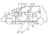
- the forced ventilation apparatus 100 of 1st Embodiment is an apparatus which performs the forced ventilation of the indoor 14 by operating the air blower 18a of the air conditioner 18 for vehicles, for example in the state in which the indoor 14 of the vehicle 10 was left at high temperature. is there.
- the forced ventilation device 100 is a device in which the power window device 17 and the air conditioner 18 are associated with a smart entry system 110 that locks and unlocks the door 15 of the vehicle 10 and a timer 120 for timekeeping.
- the vehicle 10 is, for example, an engine vehicle including an engine 11 as a driving source for traveling.
- the driver's seat of the vehicle 10 is set on the right side of the vehicle and is a so-called right-hand drive vehicle.
- the ignition switch 12 for turning on the power is turned on, power is supplied from the vehicle battery to the engine 11 and other devices described later.
- the ignition switch 12 is connected to a vehicle interior network bus 13 such as a LIN (Local Interconnect Network) or a CAN (Controller Area Network registered trademark).
- vehicle interior network bus 13 such as a LIN (Local Interconnect Network) or a CAN (Controller Area Network registered trademark).
- the ignition switch 12 may be connected to the vehicle interior network bus 13 via, for example, an ignition switch control unit.
- the vehicle 10 is provided with left and right (driver's seat side and passenger's side) front seat side doors 15a and left and right rear seat side doors 15b as doors 15 for a user to get on and off. It is a type of vehicle.
- Each door 15a, 15b is provided with a door knob 15c that serves as a grip when opening and closing.
- the door 15 is provided with a vertically openable / closable window (window glass) 16.
- the window 16 includes a front seat side window 16a provided on the front seat side door 15a and a rear seat side window 16b provided on the rear seat side door 15b. Therefore, each of the windows 16a and 16b has four settings, front, rear, left and right, like the doors 15a and 15b.
- the power window device 17 may be used as an example of an opening / closing mechanism that opens and closes the windows 16a and 16b by moving the windows 16a and 16b up and down.
- the power window device 17 includes a window motor 17a that moves the windows 16a and 16b up and down, and a body ECU 17b that controls the operation of the window motor 17a.
- the window motor 17a is provided in each door 15a, 15b so as to correspond to each window 16a, 16b.
- the body ECU 17b is connected to the vehicle interior network bus 13.
- the air conditioner 18 is an apparatus that air-conditions the interior 14 of the vehicle 10, and is disposed inside the instrument panel 19 in the interior 14.
- the air conditioner 18 includes a blower 18a, an air conditioning unit 18b, an air conditioning ECU 18c, and the like.
- the blower 18a includes a fan and a motor, and introduces air in the room 14 (inside air) or outside air (outside air) of the vehicle 10 into the air conditioning unit 18b, and a blower duct 18d provided on the downstream side of the air conditioning unit 18b. And it is the apparatus which blows into the room 14 through the blower outlet 18e opened to the room 14.
- the outlet 18 e is provided in the instrument panel 19.
- the air conditioning unit 18b includes a cooling heat exchanger provided in the refrigeration cycle apparatus in which the refrigerant is circulated and a heating heat exchanger provided in a heater circuit in which the engine cooling water is circulated, and air is blown by the blower 18a.
- the air is cooled or heated to adjust the temperature of the blown air so that the set temperature is set by the user.
- the air conditioning ECU 18c is an air conditioning control unit that controls operations of the blower 18a and the air conditioning unit 18b.
- the air conditioning ECU 18 c is connected to the vehicle interior network bus 13.
- the air conditioner 18 is provided with an air conditioner switch for operating the refrigeration cycle apparatus (cooling operation) and an inside / outside air switching switch for introducing either the inside air or the outside air.
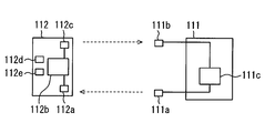
- the smart entry system 110 can lock and unlock the doors 15a and 15b without directly inserting keys into the key cylinders of the doors 15a and 15b and without manually operating the portable device 112. It is a system to do. As shown in FIGS. 1 and 2, the smart entry system 110 includes a vehicle-side main body 111 and a portable device 112, and the ignition switch 12, power window device 17, and air conditioner 18 described above are included. It is configured to work together.
- the vehicle-side main body 111 is provided in the vehicle 10 and includes a main body transmission unit 111a, a main body reception unit 111b, a main body control unit 111c, and the like.
- the main body transmission unit 111a uses an LF (low frequency) wave as a long wave to transmit an interrogation signal to the portable device 112 outside or inside the vehicle 10 (indoor 14) by wireless communication (radio wave communication).
- the main body transmission unit 111a is formed as a transmission antenna that transmits an interrogation signal.
- the main body transmission unit 111a is provided in each of the left and right front seat side doors 15a.
- the interrogation signal from the main body transmission unit 111a does not require an external trigger and is transmitted intermittently (at a predetermined transmission interval) when the vehicle is stopped.
- the main body reception unit 111b is a reception unit that receives a response signal by an RF (Radio Frequency) wave as a high frequency transmitted from the portable device 112.
- the main body reception unit 111b is formed as a reception antenna that receives a response signal.
- the main body reception unit 111b can receive a response signal from the portable device 112 from the outside or the inside (the room 14) of the vehicle 10.
- the main body receiver 111b outputs the received response signal to the main body controller 111c.
- the main body control unit 111c is a control unit that outputs an interrogation signal to the portable device 112 via the main body transmission unit 111a and receives a response signal from the portable device 112 via the main body reception unit 111b. Yes.
- the main body control unit 111c corresponds to the control unit of the present disclosure.
- the main body controller 111 c is connected to the vehicle interior network bus 13.
- the main body control unit 111c When the main body control unit 111c receives a response signal from the portable device 112 in the detection area when the doors 15a and 15b are locked or unlocked, the main body control unit 111c is registered in advance in the main body control unit 111c. Check the authentication signal. Further, when this collation is successful and the user performs an operation such as touching the door knob 15c, a command for locking or unlocking the lock mechanism of each door 15a, 15b is output. It has become.
- the operation such as contact with the door knob 15c is, for example, an operation such as touching a predetermined part of the door knob 15c or grasping the door knob 15c.
- the detection area is an area in which the portable device 112 (mobile control unit 112b) can respond to the interrogation signal from the main body transmission unit 111a, and a range in which an inquiry signal can reach from the main body transmission unit 111a. It becomes the area of.
- the detection area is an area facing the front seat side door 15a (left and right) mainly provided with the main body transmission unit 111a, and the user carrying the portable device 112 approaches the vehicle 10 in front of him The distance is short enough to see the vehicle (for example, a distance of about 5 m to 10 m).
- the portable device 112 is a portable key carried by the user, and includes a portable reception unit 112a, a portable control unit 112b, a portable transmission unit 112c, a lock button 112d, an unlock button 112e, and the like.
- the mobile receiver 112a is a receiver that receives the interrogation signal transmitted from the main body transmitter 111a and outputs the signal to the mobile controller 112b described later.
- the portable receiving unit 112a is formed as a receiving antenna that receives an interrogation signal.
- the mobile control unit 112b is a control unit that outputs a response signal required for collation to the mobile transmission unit 112c based on the interrogation signal input from the mobile reception unit 112a.
- the portable control unit 112b sends a request signal corresponding to each input signal to the main body control unit 111c. Is output (details will be described later).
- the portable transmitter 112c is a transmitter that transmits a response signal or a request signal from the portable controller 112b to the main body receiver 111b.
- the portable transmitter 112c is formed as an antenna that transmits a response signal or a request signal.
- the lock button 112d is an input unit that performs an input for locking the door 15 regardless of an interrogation signal when pressed by the user. Specifically, the lock button 112d generates a door lock request signal for requesting locking (locking) of the door 15, and outputs the door lock request signal to the portable control unit 112b. The door lock request signal is transmitted from the portable control unit 112b to the main body control unit 111c.
- the unlock button 112e is an input unit that performs an input for unlocking the door 15 regardless of the call signal when pressed by the user. Specifically, the unlock button 112e generates a door unlock request signal for requesting unlocking (unlocking) of the door 15, and outputs the door unlock request signal to the portable control unit 112b. The door unlock request signal is transmitted from the portable control unit 112b to the main body control unit 111c.
- Each of the buttons 112d and 112e is basically a button that is selected and pressed according to each request. However, apart from that, in the present embodiment, each button 112d, 112e generates a forced ventilation request signal for performing forced ventilation when operated in a manner different from the pressing operation originally used. , And can be output to the portable control unit 112b.
- the forced ventilation request signal is transmitted from the portable control unit 112b to the main body control unit 111c.
- the operation for generating the forced ventilation request signal is different from the originally used pressing operation. For example, when are sequentially pressed.
- the timer 120 serves as a time measuring means for measuring the operation time of the blower 18a during forced ventilation control, which will be described later, and is connected to the main body control unit 111c.
- the user sets the forced ventilation mode in advance by pressing the buttons 112d and 112e of the portable device 112 in advance. For example, the user generates a forced ventilation request signal by simultaneously pressing both the two buttons 112d and 112e, or pressing the two buttons 112d and 112e in order, and controls the main body from the portable control unit 112b. It is transmitted to the unit 111c.
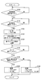
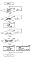
- forced ventilation control is performed based on the control flow shown in FIG.
- the situation in which this forced ventilation mode is implemented is a scene in which the vehicle 10 is stopped in a parking lot under hot weather, for example, and the user approaches the vehicle to finish driving and drive again.
- step S100 the main body control unit 111c determines whether or not the forced ventilation mode is set. If it is determined that there is a setting, the process proceeds to step S110. If it is determined NO in step S100, step S100 is repeated.
- step S110 the main body control unit 111c determines whether or not a user has been detected. Specifically, the main body control unit 111c determines whether or not the portable device 112 is detected in the detection area based on a response signal from the portable device 112 carried by the user. Furthermore, the main body control unit 111c determines whether or not the response signals can be collated.
- the main body control unit 111c transmits an interrogation signal intermittently when the vehicle is stopped.
- the portable device 112 can detect a call signal, and transmits a response signal to the main body control unit 111c in response to the call signal.
- the main body control unit 111c confirms the presence of the portable device 112 in the detection area.
- the main body control unit 111c collates the response signal with the authentication signal that it has, and if the collation is successful, the portable device 112 authenticates that it is the correct portable device 112 set in the vehicle 10. To do.
- step S110 if the main body control part 111c performs affirmation determination, ie, the detection and authentication of the portable device 112, it will progress to step S120, and if negative determination is carried out, it will repeat step S110.
- step S120 the main body controller 111c turns on the ignition switch 12, opens the window 16, and operates the blower 18a to perform forced ventilation.
- the main body control unit 111c directly or when the ignition switch 12 connected via the vehicle interior network bus 13 is provided with a control unit for the ignition switch, turns on the ignition switch. Outputs a command.
- the main body control unit 111c outputs a command for opening the window 16 to the body ECU 17b connected via the vehicle interior network bus 13.
- the window 16 to be opened is, for example, a rear seat side window 16b.
- the rear seat side window 16b is opened at a predetermined opening degree determined in advance, for example.
- the main body control unit 111c outputs a command for operating the blower 18a to the air conditioning ECU 18c connected via the vehicle interior network bus 13. For example, the blower 18a is operated at full power when a MAX voltage is applied. The blower 18a is activated regardless of whether the air conditioner switch in the air conditioner 18 is on or off and the setting of the inside / outside air changeover switch. At this time, the main body control unit 111c starts measuring time by the timer 120.
- step S130 the main body control unit 111c determines whether or not the time measured by the timer 120 has expired. Specifically, the main body control unit 111c determines whether or not the time measured by the timer 120, that is, the operating time of the blower 18a has passed a predetermined time. If the determination is affirmative in step S130, the main body control unit 111c proceeds to step S140. If the determination is negative, step S130 is repeated.
- step S140 the main body control unit 111c determines whether or not the user (mobile device 112) has been detected in the room 14. Specifically, the main body control unit 111 c determines whether or not the portable device 112 is in the room 14 based on whether or not the portable device 112 has responded to the interrogation signal transmitted to the room 14. This indicates whether the user approaching the vehicle 10 performs a contact operation on the door knob 15c, unlocks the door 15, and gets on the vehicle 10.
- step S140 the main body control unit 111c closes the window 16 and stops the blower 18a in step S150, and ends the forced ventilation by turning off the ignition switch 12. Specifically, in response to this step S150, the main body control unit 111c outputs a command for closing the window 16 to the body ECU 17b, and also causes the air-conditioning ECU 18c to stop the blower 18a. This is handled by outputting an OFF command to the ignition switch 12 (or the control unit for the ignition switch).
- step S140 the main body control unit 111c closes the window 16, stops the blower 18a, locks the door 15, and turns off the ignition switch 12 in step S160.
- the procedure for closing the window 16, stopping the blower 18a, and turning off the ignition switch 12 are the same as in step S150.
- the main body control unit 111 c locks the door 15.
- the door 15 is not unlocked (it remains locked). It will be. In this state, the main body control unit 111c maintains the locked state of the door 15.
- the portable device 112 in the smart entry system 110 and the main body control unit 111c are used, and the main body control unit is exchanged between the interrogation signal and the response signal by radio waves.
- 111c detects that the portable device 112 has entered the detection area.
- the main body control unit 111c is set in advance for forced ventilation mode.
- the response signal is successfully verified, the main body control unit 111c turns on the ignition switch 12 and opens the window 16 of the vehicle 10 by the power window device 17.
- the forced ventilation is performed by operating the blower 18a of the air conditioner 18.
- the window 16 is opened, so that effective ventilation is performed. At this time, the user is in the detection area with respect to the vehicle 10, and even if the window 16 is opened, forced ventilation is performed in front of the user's eyes, so security can be secured. It will be a thing.
- the window 16 opened at the time of forced ventilation is the window 16b on the rear seat side of the vehicle 10.
- the outlet 18e of the air conditioner 18 in the vehicle 10 is provided in the front part (instrument panel 19) of the room 14. Therefore, by setting the window 16 to be opened as the rear seat side window 16b, the air to be blown flows from the front to the rear of the room 14 and escapes to the outside from the rear seat side window 16b. Overall effective ventilation is possible.
- a timer 120 that measures the operating time of the blower 18a is provided, and the main body control unit 111c, when the operating time of the blower 18a measured by the timer 120 passes a predetermined time, The opened window 16 is closed, the blower 18a is stopped, and the ignition switch 12 is turned off.
- the main body control unit 111c locks the door 15 if the indoor unit 14 does not detect the portable device 112 even when the operation time of the blower 18a timed by the timer 120 exceeds a predetermined time. It is supposed to be.
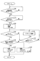
- FIG. 4 A second embodiment is shown in FIG. This embodiment opens the window 16 on the approaching side so that the user can grasp which side of the vehicle 10 is approaching when performing forced ventilation with respect to the first embodiment. It is what I did.
- the flowchart of FIG. 4 is obtained by changing step S120 of FIG. 3 described in the first embodiment to steps S121, S122, and S123.
- step S110 determines in step S110 that the portable device 112 is in the detection area and has successfully verified the response signal
- step S121 the main body control unit 111c first turns on the ignition switch 12 and activates the blower 18a. And immediately start forced ventilation.
- step S122 the main body control unit 111c sends an interrogation signal from the main body transmission unit 111a in the left and right front seat doors 15a to the right outside (driver seat side outside) and the left outside (passenger seat side outside).
- the main body control unit 111c sends an interrogation signal from the main body transmission unit 111a in the left and right front seat doors 15a to the right outside (driver seat side outside) and the left outside (passenger seat side outside).
- the portable device 112 responds to the interrogation signal transmitted from the right front seat door 15a among the left and right front seat doors 15a, it is recognized that the user is approaching from the right side of the vehicle 10.
- the portable device 112 responds to the interrogation signal transmitted from the left front seat door 15a among the left and right front seat doors 15a, the user grasps that the user is approaching from the left side of the vehicle 10. Is done.
- step S123 the main body control unit 111c opens the window 16 on the side where the user approaches when opening the window 16.
- the window to be opened is the side on which the user approaches, and it is desirable to use the rear seat side window 16b of the front seat side and the rear seat side.
- FIG. 5 A third embodiment is shown in FIG.
- the blower 18a when the blower 18a is operated by performing forced ventilation with respect to the first embodiment, when the user requests an operation to unlock the door 15, the blower 18a is operated. The door 15 is unlocked as it is.
- the flowchart of FIG. 5 is obtained by adding steps S131 and S132 to FIG. 3 described in the first embodiment.
- step S130 when the main body control unit 111c determines in step S130 after step S120 that the operation time of the blower 18a by the timer 120 has not exceeded the predetermined time, the process proceeds to step S131, and the user applies the door knob 15c to the door knob 15c. It is determined whether or not there has been an operation such as contact (operation to request unlocking of the door 15).
- step S131 If the determination in step S131 is affirmative, the body control unit 111c unlocks the door 15 while operating the blower 18a in step S132, and returns to step S130.
- FIG. 6 A fourth embodiment is shown in FIG.
- the engine 11 is started when the portable device 112 is detected in the room 14 after the blower 18a is operated for a predetermined time by performing forced ventilation with respect to the first embodiment.
- the flowchart of FIG. 6 is obtained by changing step S150 of FIG. 3 described in the first embodiment to step S151.
- the main body control unit 111c is associated with a start switch for starting the engine 11.
- the main body control unit 111c can start the engine 11 by requesting the start switch to start the engine 11.
- the main body control unit 111c determines whether the user (portable device 112) has been detected in the room 14 in step S140.
- step S140 the main body control unit 111c closes the window 16 and stops the blower 18a in step S151 to end forced ventilation, and also starts the engine 11.
- forced ventilation is automatically terminated when a predetermined time has elapsed after the operation of the blower 18a. Furthermore, if the portable device 112 is detected in the room 14, it is determined that the user has boarded. In this situation, the user can start driving immediately by starting the engine 11. That is, it is possible to smoothly perform the forced ventilation, end the operation, and start the subsequent operation.
- a dedicated mechanical switch provided on a vehicle operation panel or the like in the instrument panel 19 or a touch switch on a vehicle information display screen may be used.
- a terminal connected to the main body control unit 111c may be used.
- the main body transmission unit 111a is described as being provided on the left and right front seat doors 15a.
- the main body transmission unit 111a is also provided on the left and right rear seat doors 15b and further on the rear trunk. May be. Thereby, it becomes possible to detect the user (portable device 112) approaching the vehicle in a wider range.
- the main body transmission unit 111a is provided on the left and right front seat side doors 15a, the left and right rear seat side doors 15b, and further on the rear trunk. The user may be able to select and set whether to function.
- the window opened when implementing forced ventilation was made into the rear seat side window 16b, it is not limited to this, The ventilation capacity of the air blower 18a, or the indoor 14 to ventilate Depending on the area and the like, the front seat side window 16a may be opened. Furthermore, the window that can be opened may be a combination of the rear seat side window 16b and the front seat side window 16a (other windows).
- the window that can be opened may be set by the user to select which part of the window is to be opened when the first forced ventilation mode is set.
- the opening of the window 16 when performing forced ventilation is a predetermined opening.
- the predetermined opening means an opening having an arbitrary size such as a small opening, a medium opening, and a large opening. Furthermore, the user may be allowed to set the degree of opening when setting the first forced ventilation mode.
- the applied voltage of the blower 18a that is activated during forced ventilation is the MAX voltage, but is not limited thereto, and may be set as an arbitrary voltage.
Landscapes
- Physics & Mathematics (AREA)
- Thermal Sciences (AREA)
- Engineering & Computer Science (AREA)
- Mechanical Engineering (AREA)
- Air-Conditioning For Vehicles (AREA)
- Lock And Its Accessories (AREA)
Priority Applications (1)
| Application Number | Priority Date | Filing Date | Title |
|---|---|---|---|
| US15/519,498 US10668784B2 (en) | 2014-11-04 | 2015-10-29 | Forced-ventilation device |
Applications Claiming Priority (2)
| Application Number | Priority Date | Filing Date | Title |
|---|---|---|---|
| JP2014224474A JP6327116B2 (ja) | 2014-11-04 | 2014-11-04 | 強制換気装置 |
| JP2014-224474 | 2014-11-04 |
Publications (1)
| Publication Number | Publication Date |
|---|---|
| WO2016072069A1 true WO2016072069A1 (ja) | 2016-05-12 |
Family
ID=55908812
Family Applications (1)
| Application Number | Title | Priority Date | Filing Date |
|---|---|---|---|
| PCT/JP2015/005440 Ceased WO2016072069A1 (ja) | 2014-11-04 | 2015-10-29 | 強制換気装置 |
Country Status (3)
| Country | Link |
|---|---|
| US (1) | US10668784B2 (enExample) |
| JP (1) | JP6327116B2 (enExample) |
| WO (1) | WO2016072069A1 (enExample) |
Families Citing this family (7)
| Publication number | Priority date | Publication date | Assignee | Title |
|---|---|---|---|---|
| US10647174B2 (en) * | 2015-03-13 | 2020-05-12 | National Chin-Yi University Of Technology | In-car temperature-controlling device for car in parked state |
| JP7048189B2 (ja) * | 2018-03-07 | 2022-04-05 | 株式会社アイシン | 空調補助システム、空調補助プログラム |
| US11040601B2 (en) * | 2018-12-20 | 2021-06-22 | Ford Global Technologies, Llc | Air sanitizing apparatus for interior of vehicle and method of sanitizing air in the vehicle using the apparatus |
| JP7400191B2 (ja) | 2019-02-01 | 2023-12-19 | 株式会社アイシン | 車両換気制御システム |
| US11433734B2 (en) * | 2019-11-22 | 2022-09-06 | Toyota Motor Engineering & Manufacturing North America, Inc. | Autonomous operation of vehicle vents |
| CN112428787B (zh) * | 2020-11-26 | 2023-03-28 | 重庆长安汽车股份有限公司 | 一种汽车乘员舱自动换气的控制方法及系统 |
| US12370977B2 (en) * | 2023-07-17 | 2025-07-29 | Ford Global Technologies, Llc | Path-based detection of user approach for passive entry |
Citations (7)
| Publication number | Priority date | Publication date | Assignee | Title |
|---|---|---|---|---|
| JPH0338425A (ja) * | 1989-07-06 | 1991-02-19 | Fuji Heavy Ind Ltd | 自動車用強制換気装置 |
| JPH07137529A (ja) * | 1993-11-12 | 1995-05-30 | Suzuki Motor Corp | 車両用換気装置 |
| JP2002029385A (ja) * | 2000-05-12 | 2002-01-29 | Tokai Rika Co Ltd | 車両用遠隔操作装置 |
| JP2005206135A (ja) * | 2003-12-26 | 2005-08-04 | Zexel Valeo Climate Control Corp | 車両用換気装置 |
| JP2006273299A (ja) * | 2005-03-02 | 2006-10-12 | Nissan Motor Co Ltd | 車両用換気装置 |
| JP2007276698A (ja) * | 2006-04-10 | 2007-10-25 | Calsonic Kansei Corp | ドアロック連動強制換気システム |
| JP2013193723A (ja) * | 2012-03-23 | 2013-09-30 | Mitsubishi Motors Corp | 電動車両の自動停止装置 |
Family Cites Families (4)
| Publication number | Priority date | Publication date | Assignee | Title |
|---|---|---|---|---|
| US5167129A (en) | 1990-07-26 | 1992-12-01 | Calsonic Corporation | Automotive air conditioning system |
| JP2825335B2 (ja) | 1990-10-30 | 1998-11-18 | カルソニック株式会社 | 換気兼用車内冷房装置 |
| JPH0549421U (ja) * | 1991-12-16 | 1993-06-29 | カルソニック株式会社 | 自動車用空気調和装置 |
| JP3913661B2 (ja) * | 2002-10-09 | 2007-05-09 | 本田技研工業株式会社 | 車両用自動ドアロック施解錠装置 |
-
2014
- 2014-11-04 JP JP2014224474A patent/JP6327116B2/ja active Active
-
2015
- 2015-10-29 US US15/519,498 patent/US10668784B2/en active Active
- 2015-10-29 WO PCT/JP2015/005440 patent/WO2016072069A1/ja not_active Ceased
Patent Citations (7)
| Publication number | Priority date | Publication date | Assignee | Title |
|---|---|---|---|---|
| JPH0338425A (ja) * | 1989-07-06 | 1991-02-19 | Fuji Heavy Ind Ltd | 自動車用強制換気装置 |
| JPH07137529A (ja) * | 1993-11-12 | 1995-05-30 | Suzuki Motor Corp | 車両用換気装置 |
| JP2002029385A (ja) * | 2000-05-12 | 2002-01-29 | Tokai Rika Co Ltd | 車両用遠隔操作装置 |
| JP2005206135A (ja) * | 2003-12-26 | 2005-08-04 | Zexel Valeo Climate Control Corp | 車両用換気装置 |
| JP2006273299A (ja) * | 2005-03-02 | 2006-10-12 | Nissan Motor Co Ltd | 車両用換気装置 |
| JP2007276698A (ja) * | 2006-04-10 | 2007-10-25 | Calsonic Kansei Corp | ドアロック連動強制換気システム |
| JP2013193723A (ja) * | 2012-03-23 | 2013-09-30 | Mitsubishi Motors Corp | 電動車両の自動停止装置 |
Also Published As
| Publication number | Publication date |
|---|---|
| JP2016088263A (ja) | 2016-05-23 |
| JP6327116B2 (ja) | 2018-05-23 |
| US10668784B2 (en) | 2020-06-02 |
| US20170225541A1 (en) | 2017-08-10 |
Similar Documents
| Publication | Publication Date | Title |
|---|---|---|
| JP6327116B2 (ja) | 強制換気装置 | |
| KR100638388B1 (ko) | 키리스 엔트리장치 | |
| JP6079577B2 (ja) | 車両ドア制御装置 | |
| JP7400191B2 (ja) | 車両換気制御システム | |
| US20070290554A1 (en) | Vehicle control system | |
| JP2002077972A (ja) | 無線装置 | |
| JP2016088263A5 (enExample) | ||
| WO2014125650A1 (ja) | 車両制御装置 | |
| JP2006298014A (ja) | 車両用空調装置 | |
| JP2013147912A (ja) | 車両用ドアロックシステム | |
| JP2012046085A (ja) | 車両用空調システム | |
| JP2014213659A (ja) | 車両用空調制御装置 | |
| JP6142775B2 (ja) | 車両用エンジン始動操作システム | |
| KR20080043668A (ko) | 자동차용 pke 시스템 | |
| JP7195137B2 (ja) | 車両用ドア装置 | |
| JP2005273329A (ja) | 無線式ドア施解錠装置及び方法 | |
| JP2019081524A (ja) | 換気支援システム及び車両 | |
| JP2016088332A (ja) | 車両制御装置 | |
| JP6290690B2 (ja) | 遠隔操作システム | |
| JP4187211B2 (ja) | 車両用換気装置 | |
| JP2020197083A (ja) | スマートエントリーシステム | |
| JP6996975B2 (ja) | ドアロックシステム | |
| JP4539448B2 (ja) | 車両用スマートエントリーシステム | |
| JP2015030292A (ja) | 車両用空調システム | |
| JP2007276698A (ja) | ドアロック連動強制換気システム |
Legal Events
| Date | Code | Title | Description |
|---|---|---|---|
| 121 | Ep: the epo has been informed by wipo that ep was designated in this application |
Ref document number: 15857247 Country of ref document: EP Kind code of ref document: A1 |
|
| NENP | Non-entry into the national phase |
Ref country code: DE |
|
| 122 | Ep: pct application non-entry in european phase |
Ref document number: 15857247 Country of ref document: EP Kind code of ref document: A1 |