WO2016060103A1 - 半導体レーザ発振器 - Google Patents
半導体レーザ発振器 Download PDFInfo
- Publication number
- WO2016060103A1 WO2016060103A1 PCT/JP2015/078877 JP2015078877W WO2016060103A1 WO 2016060103 A1 WO2016060103 A1 WO 2016060103A1 JP 2015078877 W JP2015078877 W JP 2015078877W WO 2016060103 A1 WO2016060103 A1 WO 2016060103A1
- Authority
- WO
- WIPO (PCT)
- Prior art keywords
- laser
- diode
- output
- wavelength
- unit
- Prior art date
Links
Images


Classifications
-
- H—ELECTRICITY
- H01—ELECTRIC ELEMENTS
- H01S—DEVICES USING THE PROCESS OF LIGHT AMPLIFICATION BY STIMULATED EMISSION OF RADIATION [LASER] TO AMPLIFY OR GENERATE LIGHT; DEVICES USING STIMULATED EMISSION OF ELECTROMAGNETIC RADIATION IN WAVE RANGES OTHER THAN OPTICAL
- H01S5/00—Semiconductor lasers
- H01S5/04—Processes or apparatus for excitation, e.g. pumping, e.g. by electron beams
- H01S5/042—Electrical excitation ; Circuits therefor
- H01S5/0427—Electrical excitation ; Circuits therefor for applying modulation to the laser
-
- B—PERFORMING OPERATIONS; TRANSPORTING
- B23—MACHINE TOOLS; METAL-WORKING NOT OTHERWISE PROVIDED FOR
- B23K—SOLDERING OR UNSOLDERING; WELDING; CLADDING OR PLATING BY SOLDERING OR WELDING; CUTTING BY APPLYING HEAT LOCALLY, e.g. FLAME CUTTING; WORKING BY LASER BEAM
- B23K26/00—Working by laser beam, e.g. welding, cutting or boring
- B23K26/02—Positioning or observing the workpiece, e.g. with respect to the point of impact; Aligning, aiming or focusing the laser beam
- B23K26/06—Shaping the laser beam, e.g. by masks or multi-focusing
- B23K26/0604—Shaping the laser beam, e.g. by masks or multi-focusing by a combination of beams
- B23K26/0608—Shaping the laser beam, e.g. by masks or multi-focusing by a combination of beams in the same heat affected zone [HAZ]
-
- B—PERFORMING OPERATIONS; TRANSPORTING
- B23—MACHINE TOOLS; METAL-WORKING NOT OTHERWISE PROVIDED FOR
- B23K—SOLDERING OR UNSOLDERING; WELDING; CLADDING OR PLATING BY SOLDERING OR WELDING; CUTTING BY APPLYING HEAT LOCALLY, e.g. FLAME CUTTING; WORKING BY LASER BEAM
- B23K26/00—Working by laser beam, e.g. welding, cutting or boring
- B23K26/02—Positioning or observing the workpiece, e.g. with respect to the point of impact; Aligning, aiming or focusing the laser beam
- B23K26/06—Shaping the laser beam, e.g. by masks or multi-focusing
- B23K26/0604—Shaping the laser beam, e.g. by masks or multi-focusing by a combination of beams
- B23K26/0613—Shaping the laser beam, e.g. by masks or multi-focusing by a combination of beams having a common axis
-
- B—PERFORMING OPERATIONS; TRANSPORTING
- B23—MACHINE TOOLS; METAL-WORKING NOT OTHERWISE PROVIDED FOR
- B23K—SOLDERING OR UNSOLDERING; WELDING; CLADDING OR PLATING BY SOLDERING OR WELDING; CUTTING BY APPLYING HEAT LOCALLY, e.g. FLAME CUTTING; WORKING BY LASER BEAM
- B23K26/00—Working by laser beam, e.g. welding, cutting or boring
- B23K26/02—Positioning or observing the workpiece, e.g. with respect to the point of impact; Aligning, aiming or focusing the laser beam
- B23K26/06—Shaping the laser beam, e.g. by masks or multi-focusing
- B23K26/064—Shaping the laser beam, e.g. by masks or multi-focusing by means of optical elements, e.g. lenses, mirrors or prisms
-
- B—PERFORMING OPERATIONS; TRANSPORTING
- B23—MACHINE TOOLS; METAL-WORKING NOT OTHERWISE PROVIDED FOR
- B23K—SOLDERING OR UNSOLDERING; WELDING; CLADDING OR PLATING BY SOLDERING OR WELDING; CUTTING BY APPLYING HEAT LOCALLY, e.g. FLAME CUTTING; WORKING BY LASER BEAM
- B23K26/00—Working by laser beam, e.g. welding, cutting or boring
- B23K26/08—Devices involving relative movement between laser beam and workpiece
- B23K26/0869—Devices involving movement of the laser head in at least one axial direction
- B23K26/0876—Devices involving movement of the laser head in at least one axial direction in at least two axial directions
-
- B—PERFORMING OPERATIONS; TRANSPORTING
- B23—MACHINE TOOLS; METAL-WORKING NOT OTHERWISE PROVIDED FOR
- B23K—SOLDERING OR UNSOLDERING; WELDING; CLADDING OR PLATING BY SOLDERING OR WELDING; CUTTING BY APPLYING HEAT LOCALLY, e.g. FLAME CUTTING; WORKING BY LASER BEAM
- B23K26/00—Working by laser beam, e.g. welding, cutting or boring
- B23K26/36—Removing material
- B23K26/361—Removing material for deburring or mechanical trimming
-
- B—PERFORMING OPERATIONS; TRANSPORTING
- B23—MACHINE TOOLS; METAL-WORKING NOT OTHERWISE PROVIDED FOR
- B23K—SOLDERING OR UNSOLDERING; WELDING; CLADDING OR PLATING BY SOLDERING OR WELDING; CUTTING BY APPLYING HEAT LOCALLY, e.g. FLAME CUTTING; WORKING BY LASER BEAM
- B23K26/00—Working by laser beam, e.g. welding, cutting or boring
- B23K26/36—Removing material
- B23K26/362—Laser etching
-
- B—PERFORMING OPERATIONS; TRANSPORTING
- B23—MACHINE TOOLS; METAL-WORKING NOT OTHERWISE PROVIDED FOR
- B23K—SOLDERING OR UNSOLDERING; WELDING; CLADDING OR PLATING BY SOLDERING OR WELDING; CUTTING BY APPLYING HEAT LOCALLY, e.g. FLAME CUTTING; WORKING BY LASER BEAM
- B23K26/00—Working by laser beam, e.g. welding, cutting or boring
- B23K26/36—Removing material
- B23K26/38—Removing material by boring or cutting
-
- B—PERFORMING OPERATIONS; TRANSPORTING
- B23—MACHINE TOOLS; METAL-WORKING NOT OTHERWISE PROVIDED FOR
- B23K—SOLDERING OR UNSOLDERING; WELDING; CLADDING OR PLATING BY SOLDERING OR WELDING; CUTTING BY APPLYING HEAT LOCALLY, e.g. FLAME CUTTING; WORKING BY LASER BEAM
- B23K26/00—Working by laser beam, e.g. welding, cutting or boring
- B23K26/70—Auxiliary operations or equipment
- B23K26/702—Auxiliary equipment
- B23K26/703—Cooling arrangements
-
- H—ELECTRICITY
- H01—ELECTRIC ELEMENTS
- H01S—DEVICES USING THE PROCESS OF LIGHT AMPLIFICATION BY STIMULATED EMISSION OF RADIATION [LASER] TO AMPLIFY OR GENERATE LIGHT; DEVICES USING STIMULATED EMISSION OF ELECTROMAGNETIC RADIATION IN WAVE RANGES OTHER THAN OPTICAL
- H01S3/00—Lasers, i.e. devices using stimulated emission of electromagnetic radiation in the infrared, visible or ultraviolet wave range
- H01S3/10—Controlling the intensity, frequency, phase, polarisation or direction of the emitted radiation, e.g. switching, gating, modulating or demodulating
- H01S3/13—Stabilisation of laser output parameters, e.g. frequency or amplitude
- H01S3/131—Stabilisation of laser output parameters, e.g. frequency or amplitude by controlling the active medium, e.g. by controlling the processes or apparatus for excitation
-
- H—ELECTRICITY
- H01—ELECTRIC ELEMENTS
- H01S—DEVICES USING THE PROCESS OF LIGHT AMPLIFICATION BY STIMULATED EMISSION OF RADIATION [LASER] TO AMPLIFY OR GENERATE LIGHT; DEVICES USING STIMULATED EMISSION OF ELECTROMAGNETIC RADIATION IN WAVE RANGES OTHER THAN OPTICAL
- H01S5/00—Semiconductor lasers
- H01S5/005—Optical components external to the laser cavity, specially adapted therefor, e.g. for homogenisation or merging of the beams or for manipulating laser pulses, e.g. pulse shaping
- H01S5/0071—Optical components external to the laser cavity, specially adapted therefor, e.g. for homogenisation or merging of the beams or for manipulating laser pulses, e.g. pulse shaping for beam steering, e.g. using a mirror outside the cavity to change the beam direction
-
- H—ELECTRICITY
- H01—ELECTRIC ELEMENTS
- H01S—DEVICES USING THE PROCESS OF LIGHT AMPLIFICATION BY STIMULATED EMISSION OF RADIATION [LASER] TO AMPLIFY OR GENERATE LIGHT; DEVICES USING STIMULATED EMISSION OF ELECTROMAGNETIC RADIATION IN WAVE RANGES OTHER THAN OPTICAL
- H01S5/00—Semiconductor lasers
- H01S5/04—Processes or apparatus for excitation, e.g. pumping, e.g. by electron beams
- H01S5/042—Electrical excitation ; Circuits therefor
-
- H—ELECTRICITY
- H01—ELECTRIC ELEMENTS
- H01S—DEVICES USING THE PROCESS OF LIGHT AMPLIFICATION BY STIMULATED EMISSION OF RADIATION [LASER] TO AMPLIFY OR GENERATE LIGHT; DEVICES USING STIMULATED EMISSION OF ELECTROMAGNETIC RADIATION IN WAVE RANGES OTHER THAN OPTICAL
- H01S5/00—Semiconductor lasers
- H01S5/06—Arrangements for controlling the laser output parameters, e.g. by operating on the active medium
- H01S5/068—Stabilisation of laser output parameters
- H01S5/0683—Stabilisation of laser output parameters by monitoring the optical output parameters
-
- H—ELECTRICITY
- H01—ELECTRIC ELEMENTS
- H01S—DEVICES USING THE PROCESS OF LIGHT AMPLIFICATION BY STIMULATED EMISSION OF RADIATION [LASER] TO AMPLIFY OR GENERATE LIGHT; DEVICES USING STIMULATED EMISSION OF ELECTROMAGNETIC RADIATION IN WAVE RANGES OTHER THAN OPTICAL
- H01S5/00—Semiconductor lasers
- H01S5/40—Arrangement of two or more semiconductor lasers, not provided for in groups H01S5/02 - H01S5/30
- H01S5/4012—Beam combining, e.g. by the use of fibres, gratings, polarisers, prisms
-
- H—ELECTRICITY
- H01—ELECTRIC ELEMENTS
- H01S—DEVICES USING THE PROCESS OF LIGHT AMPLIFICATION BY STIMULATED EMISSION OF RADIATION [LASER] TO AMPLIFY OR GENERATE LIGHT; DEVICES USING STIMULATED EMISSION OF ELECTROMAGNETIC RADIATION IN WAVE RANGES OTHER THAN OPTICAL
- H01S5/00—Semiconductor lasers
- H01S5/40—Arrangement of two or more semiconductor lasers, not provided for in groups H01S5/02 - H01S5/30
- H01S5/4018—Lasers electrically in series
-
- H—ELECTRICITY
- H01—ELECTRIC ELEMENTS
- H01S—DEVICES USING THE PROCESS OF LIGHT AMPLIFICATION BY STIMULATED EMISSION OF RADIATION [LASER] TO AMPLIFY OR GENERATE LIGHT; DEVICES USING STIMULATED EMISSION OF ELECTROMAGNETIC RADIATION IN WAVE RANGES OTHER THAN OPTICAL
- H01S5/00—Semiconductor lasers
- H01S5/40—Arrangement of two or more semiconductor lasers, not provided for in groups H01S5/02 - H01S5/30
- H01S5/4025—Array arrangements, e.g. constituted by discrete laser diodes or laser bar
- H01S5/4031—Edge-emitting structures
- H01S5/4062—Edge-emitting structures with an external cavity or using internal filters, e.g. Talbot filters
-
- H—ELECTRICITY
- H01—ELECTRIC ELEMENTS
- H01S—DEVICES USING THE PROCESS OF LIGHT AMPLIFICATION BY STIMULATED EMISSION OF RADIATION [LASER] TO AMPLIFY OR GENERATE LIGHT; DEVICES USING STIMULATED EMISSION OF ELECTROMAGNETIC RADIATION IN WAVE RANGES OTHER THAN OPTICAL
- H01S5/00—Semiconductor lasers
- H01S5/005—Optical components external to the laser cavity, specially adapted therefor, e.g. for homogenisation or merging of the beams or for manipulating laser pulses, e.g. pulse shaping
-
- H—ELECTRICITY
- H01—ELECTRIC ELEMENTS
- H01S—DEVICES USING THE PROCESS OF LIGHT AMPLIFICATION BY STIMULATED EMISSION OF RADIATION [LASER] TO AMPLIFY OR GENERATE LIGHT; DEVICES USING STIMULATED EMISSION OF ELECTROMAGNETIC RADIATION IN WAVE RANGES OTHER THAN OPTICAL
- H01S5/00—Semiconductor lasers
- H01S5/02—Structural details or components not essential to laser action
- H01S5/022—Mountings; Housings
- H01S5/023—Mount members, e.g. sub-mount members
- H01S5/02325—Mechanically integrated components on mount members or optical micro-benches
- H01S5/02326—Arrangements for relative positioning of laser diodes and optical components, e.g. grooves in the mount to fix optical fibres or lenses
-
- H—ELECTRICITY
- H01—ELECTRIC ELEMENTS
- H01S—DEVICES USING THE PROCESS OF LIGHT AMPLIFICATION BY STIMULATED EMISSION OF RADIATION [LASER] TO AMPLIFY OR GENERATE LIGHT; DEVICES USING STIMULATED EMISSION OF ELECTROMAGNETIC RADIATION IN WAVE RANGES OTHER THAN OPTICAL
- H01S5/00—Semiconductor lasers
- H01S5/02—Structural details or components not essential to laser action
- H01S5/024—Arrangements for thermal management
- H01S5/02407—Active cooling, e.g. the laser temperature is controlled by a thermo-electric cooler or water cooling
- H01S5/02423—Liquid cooling, e.g. a liquid cools a mount of the laser
-
- H—ELECTRICITY
- H01—ELECTRIC ELEMENTS
- H01S—DEVICES USING THE PROCESS OF LIGHT AMPLIFICATION BY STIMULATED EMISSION OF RADIATION [LASER] TO AMPLIFY OR GENERATE LIGHT; DEVICES USING STIMULATED EMISSION OF ELECTROMAGNETIC RADIATION IN WAVE RANGES OTHER THAN OPTICAL
- H01S5/00—Semiconductor lasers
- H01S5/06—Arrangements for controlling the laser output parameters, e.g. by operating on the active medium
- H01S5/0617—Arrangements for controlling the laser output parameters, e.g. by operating on the active medium using memorised or pre-programmed laser characteristics
-
- H—ELECTRICITY
- H01—ELECTRIC ELEMENTS
- H01S—DEVICES USING THE PROCESS OF LIGHT AMPLIFICATION BY STIMULATED EMISSION OF RADIATION [LASER] TO AMPLIFY OR GENERATE LIGHT; DEVICES USING STIMULATED EMISSION OF ELECTROMAGNETIC RADIATION IN WAVE RANGES OTHER THAN OPTICAL
- H01S5/00—Semiconductor lasers
- H01S5/10—Construction or shape of the optical resonator, e.g. extended or external cavity, coupled cavities, bent-guide, varying width, thickness or composition of the active region
- H01S5/14—External cavity lasers
- H01S5/141—External cavity lasers using a wavelength selective device, e.g. a grating or etalon
-
- H—ELECTRICITY
- H01—ELECTRIC ELEMENTS
- H01S—DEVICES USING THE PROCESS OF LIGHT AMPLIFICATION BY STIMULATED EMISSION OF RADIATION [LASER] TO AMPLIFY OR GENERATE LIGHT; DEVICES USING STIMULATED EMISSION OF ELECTROMAGNETIC RADIATION IN WAVE RANGES OTHER THAN OPTICAL
- H01S5/00—Semiconductor lasers
- H01S5/40—Arrangement of two or more semiconductor lasers, not provided for in groups H01S5/02 - H01S5/30
- H01S5/4025—Array arrangements, e.g. constituted by discrete laser diodes or laser bar
- H01S5/4087—Array arrangements, e.g. constituted by discrete laser diodes or laser bar emitting more than one wavelength
Definitions
- the present disclosure relates to a semiconductor laser oscillator that emits a laser.
- DDL direct diode laser
- a DDL oscillator composed of a single-emitter laser diode
- the DDL oscillator In the DDL oscillator, high output and high brightness are achieved by combining spectral beams. In order to realize spectral beam combining of lasers having a plurality of wavelengths, it is necessary to narrow the spectrum of each wavelength. Therefore, the DDL oscillator locks the laser to a plurality of desired wavelengths by an external resonator.
- the higher the wavelength lock efficiency the more efficiently the spectral beam can be coupled, and a highly efficient laser output can be obtained.
- laser diodes manufactured from a plurality of types of materials are distributed to each lock wavelength so that the wavelength lock efficiency becomes high at least at high output.
- the laser diode has a characteristic that the wavelength of the emitted laser shifts to the longer wavelength side by about 0.25 to 0.3 nm with a temperature rise of 1 ° C. Therefore, if the output of the laser diode is increased, the amount of heat generated increases and the temperature rises, so that the wavelength of the emitted laser shifts to the longer wavelength side. Therefore, a material whose wavelength is adjusted according to the time of high output may be difficult to maintain the high wavelength lock efficiency because the wavelength shifts to a low wavelength at the time of low output even though the wavelength lock efficiency is high.
- the laser output with respect to the input current of a normal laser diode that is not wavelength locked is a straight line.
- the higher the current is supplied to the laser diode the larger the temperature difference from the low output and the larger the wavelength shift amount.
- the efficiency at the low output tends to decrease.
- the relationship between the input current to the laser diode of each bank in the DDL oscillator and the laser output is not a straight line, and the characteristic is a downward convex curve at low output.
- the laser with low wavelength lock efficiency and oscillating at a wavelength other than the lock wavelength increases the loss of the laser to be emitted off the original optical axis. Then, the loss generates heat in the semiconductor laser oscillator and local heat in the transmission fiber incident portion. Therefore, the performance of the semiconductor laser oscillator cannot be maximized.
- An object of the embodiment is to provide a semiconductor laser oscillator that can maintain a highly efficient wavelength lock even at a low output in a semiconductor laser oscillator that is wavelength-locked and spectrally beam-coupled.
- a plurality of laser diodes connected in series constitute one bank, and a plurality of banks are connected in parallel to each other, and each of the plurality of banks includes a diode unit.
- a semiconductor laser oscillator further comprising a control unit that individually controls input current in accordance with wavelength lock efficiency characteristics to control the output of the entire diode unit to a required output.
- a highly efficient wavelength lock can be maintained even when the output is low in the semiconductor laser oscillator in which the wavelength is locked and the spectrum beam is coupled.
- FIG. 1 is a perspective view showing an overall configuration of a laser processing machine including a semiconductor laser oscillator according to an embodiment.
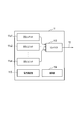
- FIG. 2 is a block diagram illustrating a semiconductor laser oscillator according to an embodiment.
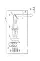
- FIG. 3 is a conceptual diagram showing a specific configuration of the DDL unit in FIG.
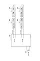
- FIG. 4 is a diagram for explaining banks set in the DDL unit in FIG.
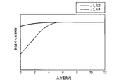
- FIG. 5 is a diagram for explaining that the characteristics of wavelength lock efficiency differ depending on the laser wavelength.
- FIG. 6 is a DDL characteristic diagram showing a relationship between a general input current and laser power.
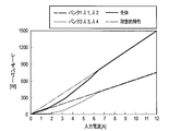
- FIG. 7 is a characteristic diagram showing the relationship between the input current to each bank, the laser output, and the DDL unit output (bank total laser output) with respect to the command output value in one embodiment.
- the laser processing machine 100 shown in FIG. 1 is an example of a laser cutting machine that cuts a workpiece with a laser.
- the laser processing machine may be a laser welding processing machine that welds a workpiece with a laser, a surface modification device that modifies the surface of the workpiece with a laser, or a marking device that marks a workpiece with a laser. .
- the laser processing machine 100 includes a laser oscillator 11 that generates and emits a laser LB, a laser processing unit 15, and a process fiber 12 that transmits the laser LB to the laser processing unit 15.
- the laser oscillator 11 is a DDL oscillator as an example. Hereinafter, it is referred to as a DDL oscillator 11. The specific configuration and operation of the DDL oscillator 11 will be described in detail later.
- the laser oscillator 11 only needs to have a wavelength lock mechanism, and is not limited to a DDL oscillator.
- the process fiber 12 is mounted along X-axis and Y-axis cable ducts (not shown) arranged in the laser processing unit 15.
- the laser processing unit 15 includes a processing table 21 on which a workpiece W is placed, a portal-shaped X-axis carriage 22 that is movable in the X-axis direction on the processing table 21, and a perpendicular to the X-axis on the X-axis carriage 22. And a Y-axis carriage 23 that is movable in the Y-axis direction. Further, the laser processing unit 15 has a collimator unit 29 fixed to the Y-axis carriage 23.
- the collimator unit 29 includes a collimator lens 28 that converts the laser beam LB emitted from the output end of the process fiber 12 into a substantially parallel light beam, and a laser beam LB that has been converted into a substantially parallel light beam in the lower direction in the Z-axis direction perpendicular to the X and Y axes. And a bend mirror 25 that reflects toward the surface. Further, the collimator unit 29 includes a condenser lens 27 that condenses the laser LB reflected by the bend mirror 25 and a processing head 26.
- the collimating lens 28, the bend mirror 25, the condenser lens 27, and the processing head 26 are fixed in the collimator unit 29 with the optical axis adjusted in advance.
- the collimating lens 28 may be configured to move in the X-axis direction.
- the collimator unit 29 is fixed to a Y-axis carriage 23 movable in the Y-axis direction, and the Y-axis carriage 23 is provided on an X-axis carriage 22 movable in the X-axis direction. Therefore, the laser processing unit 15 can move the position at which the workpiece W is irradiated with the laser LB emitted from the processing head 26 in the X-axis direction and the Y-axis direction.
- the laser processing machine 100 transmits the laser LB emitted from the DDL oscillator 11 to the laser processing unit 15 through the process fiber 12, and irradiates the workpiece W in a high energy density state.
- the material W can be cut.
- an assist gas for removing the melt is injected into the workpiece W.
- FIG. 1 the illustration of the configuration for injecting the assist gas is omitted.
- the DDL oscillator 11 includes n DDL units of the DDL units 11u1 to 11un, and a combiner 112 that spatially couples the laser beams emitted from the DDL units 11u1 to 11un.
- the DDL units 11u1 to 11un are examples of diode units.
- the DDL oscillator 11 includes a power supply unit 113 that supplies power to the DDL units 11u1 to 11un, and a control unit 114 that controls the DDL oscillator 11.
- the power supply unit 113 can be configured by a power supply circuit.
- the control unit 114 can be configured by a microprocessor or a microcomputer.
- a DDL unit that does not specify any of the DDL units 11u1 to 11un is referred to as a DDL unit 11u.
- the number n of the DDL units 11u is 1 or more, and may be set as appropriate according to the output required by the emitted laser LB. In addition, when there is one DDL unit 11u, a combiner is not necessary.
- the DDL unit 11u is specifically configured as shown in FIG.
- the DDL unit 11u has n laser diode modules of laser diode modules Um1 to Umn.
- a laser diode module that does not specify any of the laser diode modules Um1 to Umn is referred to as a laser diode module Um.
- the number n of the laser diode modules Um may be set as appropriate.
- Each laser diode module Um is configured by connecting a plurality of laser diodes in series.
- the number of laser diodes is 14, for example.
- Each laser diode module Um has a different laser wavelength to be locked.
- each laser diode is spatially coupled to one end of the optical fibers Uf1 to Ufn.
- a high reflection mirror is formed on the end face of each laser diode opposite to the laser emitting side.
- the other end of the optical fibers Uf1 to Ufn is a fiber array U11.
- the tip portions of the optical fibers Uf1 to Ufn are optical fiber arrays arranged in a line in a direction orthogonal to the laser emission direction. A range of several millimeters to several tens of millimeters at the tip of the optical fiber array is covered with a resin, for example, in a cylindrical shape, so that a fiber array U11 is configured.
- the lasers emitted from the laser diode modules Um1 to Umn are emitted from the fiber array U11, and are collimated by the collimating lens U12 to become a substantially parallel light beam.
- the laser beams emitted from the collimator lens U12 are incident on the grating U13 at different angles, bent in directions, and emitted through the partial reflection mirror U14.
- the incident angle to the grating U13 is determined by the difference in the position where the laser enters the collimating lens U12.
- a part of the laser is reflected by the partial reflection mirror U14, returns to each laser diode of the laser diode module Um, is reflected by the high reflection mirror, and enters the partial reflection mirror U14 again.
- the laser resonates between the high reflection mirror and the partial reflection mirror U14 inside the laser diode module Um.
- the DDL unit 11u constitutes an external resonator.
- the high reflection mirror and the partial reflection mirror U14 constitute an external resonator mirror.
- the DDL unit 11u causes the wavelength of the laser to be locked by the external resonator and the grating U13.
- the grating U13 has a function of combining spectral beams in addition to the function of wavelength locking.
- the DDL unit 11u outputs a laser having a wavelength spectrum SP1 as shown in the figure locked to a plurality of wavelengths.
- FIG. 4 shows a configuration example of banks set in the DDL unit 11u. In the present embodiment, it is assumed that two banks are set in the DDL unit 11u. The number of banks may be three or more.
- a plurality of laser diode modules Um are connected in series to each bank.
- two laser diode modules Um are connected in series, but three laser diode modules Um may be connected in series.
- the number of laser diodes connected in series should be such that the voltage is easily controlled, for example, 50 to 75V.
- a voltage of 50 to 75 V is supplied to each bank from the power supply unit 113, and a current of 0 to 12 A flows.
- the DDL unit 11u outputs lasers locked to the wavelengths ⁇ 1 to ⁇ 4. Note that, for example, a laser having a wavelength of 910 nm to 950 nm is output from the entire DDL units 11u1 to 11un in FIG.
- the wavelengths ⁇ 1 and ⁇ 2 have high wavelength lock efficiency in almost the entire output region where the input current is 0 to 12A.
- the wavelengths ⁇ 3 and ⁇ 4 have low wavelength lock efficiency in a low output region where the input current is about 0 to 4A.
- the laser output has the characteristics shown in FIG. 6 with respect to the input current.
- the alternate long and short dash line indicates the laser output characteristics with respect to the input current in the bank 1 that outputs the lasers locked to the wavelengths ⁇ 1 and ⁇ 2
- the broken line indicates the bank that outputs the lasers locked to the wavelengths ⁇ 3 and ⁇ 4.
- the solid line represents the output characteristics of the DDL unit 11u (the sum of bank 1 and bank 2) with respect to the input current in FIG.
- the relationship between the input current and the laser power is ideally linear as shown by the two-dot chain line.
- the characteristic of the DDL unit 11u as a whole becomes a downward convex curve, as indicated by the solid line.
- the banks 1 and 2 are controlled as shown in FIG. As described above, the wavelengths ⁇ 1 and ⁇ 2 having high wavelength lock efficiency from low output to high output are assigned to the bank 1, and the wavelengths ⁇ 3 and ⁇ 4 having low wavelength lock efficiency are assigned to the bank 2 at the time of low output. It has been.
- the control unit 114 instructs the bank 1 to output a laser power from a low output to a high output as indicated by a one-dot chain line. Specifically, after the input current is linearly increased from 0 to about 400 W, the input current is once set to 0. When the command power value is about 400 W or more, the input current is linearly increased from 0 to 12A.
- the control unit 114 commands the bank 2 so that the laser power to be output at low output is 0 and the laser power is output at medium output or higher, as indicated by a broken line. Specifically, the input current is set to 0 when the command power value is about 0 to 400 W. When the command power value is about 400 W, the input current is increased to about 6 A, and thereafter, the input current is increased linearly to 12 A.
- the control unit 114 controls the banks 1 and 2 as shown in FIG. 7 so that the DDL unit 11u as a whole can be output as shown by the solid line, and the characteristics approaching the ideal characteristics shown by the two-dot chain line. It can be.
- control unit 114 individually controls the input current to the laser diode of each of the plurality of banks in accordance with the characteristics of the wavelength lock efficiency.
- the control unit 114 includes a plurality of banks so that a laser power obtained by synthesizing lasers output from each of the plurality of banks can be a required oscillator output, and the wavelength lock efficiency can be maintained high in the entire output region of the oscillator.
- the input current to each laser diode may be individually controlled.
- the plurality of banks have a first wavelength lock efficiency at a low current from 0 to a predetermined value of the input current, and a wavelength lock efficiency higher than that of the first state.
- the control unit 114 may control as follows.
- the control unit 114 controls the output of the second bank so that the output required for the entire DDL unit 11u is 0 from 0 to a predetermined value.
- the semiconductor laser oscillator of this embodiment it becomes possible to improve the wavelength lock efficiency when the output of the oscillator is low, and at the same time, it is used in a region where the electro-optical conversion efficiency is also high. Electric power can be reduced.
- heat generation inside the oscillator affected by output loss due to a decrease in wavelength lock efficiency and local heat generation of the transmission fiber can be prevented, the output of the oscillator can be stabilized, and optical components can be damaged. Can be prevented.
- the laser diode is, for example, a single emitter laser diode.
- the laser diode may be a laser diode module in which a plurality of single-emitter laser diodes are spatially coupled.
- the laser diode may be a diode laser bar.
- the laser diode may be a laser diode module in which a plurality of diode laser bars are spatially coupled.
- the diode laser bar is a chip in which emitters are arranged horizontally at intervals of, for example, 500 ⁇ m.
- the present invention can be used for a semiconductor laser oscillator that emits a laser.
Abstract
Description
Claims (6)
- 直列に接続された複数のレーザダイオードが1つのバンクを構成し、複数のバンクから構成されたダイオードユニットを備え、
前記ダイオードユニットは、複数の波長にロックさせる波長ロック機構を有し、
前記複数のバンクそれぞれのレーザダイオードへの入力電流を波長ロック効率の特性に対応させて個別に制御して、前記ダイオードユニット全体の出力を要求される出力に制御する制御部をさらに備える
ことを特徴とする半導体レーザ発振器。 - レーザダイオードがシングルエミッタのレーザダイオードであることを特徴とする請求項1記載の半導体レーザ発振器。
- レーザダイオードがシングルエミッタのレーザダイオードを複数空間結合したレーザダイオードモジュールであることを特徴とする請求項1記載の半導体レーザ発振器。
- レーザダイオードがダイオードレーザバーであることを特徴とする請求項1記載の半導体レーザ発振器。
- レーザダイオードがダイオードレーザバーを複数空間結合したレーザダイオードモジュールであることを特徴とする請求項1記載の半導体レーザ発振器。
- 前記複数のバンクは、入力電流が0から所定の値までの低電流時の波長ロック効率が第1の状態である第1のバンクと、前記低電流時の波長ロック効率が前記第1の状態よりも低い第2の状態である第2のバンクとを少なくとも含み、
前記制御部は、前記第2のバンクの出力を、前記ダイオードユニット全体に要求される出力が0から所定の値まで0とするよう制御する
ことを特徴とする請求項1~5のいずれか1項に記載の半導体レーザ発振器。
Priority Applications (4)
| Application Number | Priority Date | Filing Date | Title |
|---|---|---|---|
| US15/504,820 US9917416B2 (en) | 2014-10-15 | 2015-10-13 | Semiconductor laser oscillator |
| CN201580046559.0A CN107078461B (zh) | 2014-10-15 | 2015-10-13 | 半导体激光振荡器 |
| EP15851517.1A EP3208898A4 (en) | 2014-10-15 | 2015-10-13 | Semiconductor laser oscillator |
| JP2016554076A JP6374017B2 (ja) | 2014-10-15 | 2015-10-13 | 半導体レーザ発振器 |
Applications Claiming Priority (2)
| Application Number | Priority Date | Filing Date | Title |
|---|---|---|---|
| JP2014210491 | 2014-10-15 | ||
| JP2014-210491 | 2014-10-15 |
Publications (1)
| Publication Number | Publication Date |
|---|---|
| WO2016060103A1 true WO2016060103A1 (ja) | 2016-04-21 |
Family
ID=55746649
Family Applications (2)
| Application Number | Title | Priority Date | Filing Date |
|---|---|---|---|
| PCT/US2015/054713 WO2016060933A1 (en) | 2014-10-15 | 2015-10-08 | Laser system and method of tuning the output power of the laser system |
| PCT/JP2015/078877 WO2016060103A1 (ja) | 2014-10-15 | 2015-10-13 | 半導体レーザ発振器 |
Family Applications Before (1)
| Application Number | Title | Priority Date | Filing Date |
|---|---|---|---|
| PCT/US2015/054713 WO2016060933A1 (en) | 2014-10-15 | 2015-10-08 | Laser system and method of tuning the output power of the laser system |
Country Status (5)
| Country | Link |
|---|---|
| US (2) | US10305252B2 (ja) |
| EP (2) | EP3207602A4 (ja) |
| JP (2) | JP6652555B2 (ja) |
| CN (2) | CN107005020B (ja) |
| WO (2) | WO2016060933A1 (ja) |
Cited By (2)
| Publication number | Priority date | Publication date | Assignee | Title |
|---|---|---|---|---|
| JP2018061006A (ja) * | 2016-09-30 | 2018-04-12 | 日亜化学工業株式会社 | 光源装置 |
| JP2021525003A (ja) * | 2018-05-24 | 2021-09-16 | パナソニックIpマネジメント株式会社 | 角度調節を有する交換可能レーザ共振器 |
Families Citing this family (26)
| Publication number | Priority date | Publication date | Assignee | Title |
|---|---|---|---|---|
| WO2016060933A1 (en) | 2014-10-15 | 2016-04-21 | Lumentum Operations Llc | Laser system and method of tuning the output power of the laser system |
| KR20170104818A (ko) * | 2016-03-08 | 2017-09-18 | 주식회사 이오테크닉스 | 벨로우즈 용접이 가능한 레이저 용접 장치 |
| JP6625914B2 (ja) * | 2016-03-17 | 2019-12-25 | ファナック株式会社 | 機械学習装置、レーザ加工システムおよび機械学習方法 |
| US11179802B2 (en) * | 2016-07-14 | 2021-11-23 | Mitsubishi Electric Corporation | Laser machining head and laser machining apparatus |
| EP3504944B1 (en) * | 2016-08-26 | 2023-06-07 | NLIGHT, Inc. | Laser power distribution module |
| GB2556197B (en) * | 2016-09-30 | 2021-11-24 | Nichia Corp | Light source device |
| CN109891693B (zh) * | 2016-10-25 | 2020-10-20 | 三菱电机株式会社 | 激光加工机及激光加工机的运算装置 |
| CN108075351A (zh) * | 2016-11-11 | 2018-05-25 | 大族激光科技产业集团股份有限公司 | 半导体激光器控制系统 |
| CN106532431A (zh) * | 2016-12-28 | 2017-03-22 | 尚华 | 一种应用于人体内的激光发生光导入装置 |
| JP6568136B2 (ja) * | 2017-04-06 | 2019-08-28 | ファナック株式会社 | 複数のレーザモジュールを備えたレーザ装置 |
| JP6502993B2 (ja) * | 2017-04-06 | 2019-04-17 | ファナック株式会社 | 複数のレーザモジュールを備えたレーザ装置 |
| JP6642546B2 (ja) * | 2017-09-21 | 2020-02-05 | 日亜化学工業株式会社 | 波長ビーム結合装置 |
| DE102017129790A1 (de) * | 2017-12-13 | 2019-06-13 | Osram Opto Semiconductors Gmbh | Verfahren zum Betreiben einer Laservorrichtung und Laservorrichtung |
| JP6970036B2 (ja) | 2018-02-20 | 2021-11-24 | ファナック株式会社 | ファイバレーザ発振器用の電源回路 |
| US10461851B1 (en) * | 2018-03-30 | 2019-10-29 | Facebook, Inc. | Predicting optical transceiver failure |
| US10425156B1 (en) | 2018-03-30 | 2019-09-24 | Facebook, Inc. | Dynamically determining optical transceiver expected life |
| GB2573303A (en) * | 2018-05-01 | 2019-11-06 | Datalase Ltd | System and method for laser marking |
| CN112136254B (zh) * | 2018-05-07 | 2021-07-13 | 三菱电机株式会社 | 激光装置、激光加工机及激光装置的输出控制方法 |
| US10951007B2 (en) | 2018-05-11 | 2021-03-16 | Excelitas Technologies Corp. | Optically pumped tunable VCSEL employing geometric isolation |
| CN110994352A (zh) * | 2019-11-11 | 2020-04-10 | 无锡锐科光纤激光技术有限责任公司 | 可拓展的分布式激光器 |
| CN110854654B (zh) * | 2019-11-18 | 2021-06-15 | 无锡锐科光纤激光技术有限责任公司 | 一种半闭环控制激光器 |
| CN111162454B (zh) * | 2020-01-02 | 2021-03-12 | 中国科学院半导体研究所 | 一种宽波段调谐系统及调谐方法 |
| JP2021118271A (ja) * | 2020-01-27 | 2021-08-10 | パナソニックIpマネジメント株式会社 | レーザ発振器及びレーザ加工方法 |
| US11769981B1 (en) * | 2020-03-27 | 2023-09-26 | Government Of The United States As Represented By The Secretary Of The Air Force | Circuit and method for regulating currents to multiple loads |
| CN111682399B (zh) * | 2020-06-20 | 2021-07-20 | 深圳市灵明光子科技有限公司 | 激光发射器驱动电路、系统及高速光通信装置 |
| WO2023191788A1 (en) * | 2022-03-31 | 2023-10-05 | Intel Corporation | Laser transmitter component, light detection and ranging system, and computer readable medium |
Citations (10)
| Publication number | Priority date | Publication date | Assignee | Title |
|---|---|---|---|---|
| JP2683158B2 (ja) * | 1993-01-22 | 1997-11-26 | ドイチェ フォルシュングスアンシュタルト フュア ルフト− ウント ラウムファールト エー.ファウ. | 電力制御分割化レーザー・システム |
| JP2001284732A (ja) * | 2000-03-31 | 2001-10-12 | Matsushita Electric Ind Co Ltd | 多波長レーザ発光装置、当該装置に用いられる半導体レーザアレイ素子及び当該半導体レーザアレイ素子の製造方法 |
| JP2002335042A (ja) * | 2001-05-11 | 2002-11-22 | Mitsubishi Chemicals Corp | 外部共振器付きレーザダイオードモジュールの波長ロックの光出力範囲を広くする方法、および該方法を実施するためのレーザダイオードモジュール |
| US20090190218A1 (en) * | 2006-07-18 | 2009-07-30 | Govorkov Sergei V | High power and high brightness diode-laser array for material processing applications |
| JP2010263063A (ja) * | 2009-05-07 | 2010-11-18 | Sumitomo Heavy Ind Ltd | レーザ照射装置 |
| JP2012174720A (ja) * | 2011-02-17 | 2012-09-10 | Fanuc Ltd | 精確にレーザ出力を補正できる高出力レーザ装置 |
| JP2013197371A (ja) * | 2012-03-21 | 2013-09-30 | Fujikura Ltd | 駆動回路、光源装置、光増幅器、および、駆動方法 |
| JP2013233556A (ja) * | 2012-05-08 | 2013-11-21 | Product Support:Kk | レーザー加工装置 |
| JP2014104479A (ja) * | 2012-11-27 | 2014-06-09 | Amada Co Ltd | ファイバーレーザ加工機及び断線検出方法 |
| WO2014133013A1 (ja) * | 2013-02-27 | 2014-09-04 | コマツ産機株式会社 | ファイバレーザ加工機の出力制御方法及びファイバレーザ加工機 |
Family Cites Families (51)
| Publication number | Priority date | Publication date | Assignee | Title |
|---|---|---|---|---|
| US4439861A (en) | 1981-08-07 | 1984-03-27 | Mrj, Inc. | Solid state laser with controlled optical pumping |
| US5337325A (en) * | 1992-05-04 | 1994-08-09 | Photon Imaging Corp | Semiconductor, light-emitting devices |
| US5729568A (en) | 1993-01-22 | 1998-03-17 | Deutsche Forschungsanstalt Fuer Luft-Und Raumfahrt E.V. | Power-controlled, fractal laser system |
| DE19623883A1 (de) * | 1996-06-05 | 1997-12-11 | Siemens Ag | Optische Sendeeinrichtung |
| US5748654A (en) | 1996-06-17 | 1998-05-05 | Trw Inc. | Diode array providing either a pulsed or a CW mode of operation of a diode pumped solid state laser |
| US5715270A (en) * | 1996-09-27 | 1998-02-03 | Mcdonnell Douglas Corporation | High efficiency, high power direct diode laser systems and methods therefor |
| US6094447A (en) * | 1998-06-12 | 2000-07-25 | Lockheed Martin Corporation | System and method for reducing wavefront distortion in high-gain diode-pumped laser media |
| SE518827C2 (sv) * | 1999-02-17 | 2002-11-26 | Altitun Ab | Metod för karakterisering av en avstämbar laser |
| US6799242B1 (en) * | 1999-03-05 | 2004-09-28 | Sanyo Electric Co., Ltd. | Optical disc player with sleep mode |
| US6826224B2 (en) | 2000-03-27 | 2004-11-30 | Matsushita Electric Industrial Co., Ltd. | High-power semiconductor laser array apparatus that outputs laser lights matched in wavelength and phase, manufacturing method therefor, and multi-wavelength laser emitting apparatus using such high-power semiconductor laser array apparatus |
| EP1143584A3 (en) | 2000-03-31 | 2003-04-23 | Matsushita Electric Industrial Co., Ltd. | Semiconductor laser array |
| EP1146617A3 (en) | 2000-03-31 | 2003-04-23 | Matsushita Electric Industrial Co., Ltd. | High-powered semiconductor laser array apparatus |
| US6518563B1 (en) * | 2000-06-22 | 2003-02-11 | Agere Systems Inc. | Detecting aging of optical components |
| EP1346445B1 (en) * | 2000-08-09 | 2011-11-09 | Santur Corporation | Tunable distributed feedback laser |
| WO2002066197A1 (fr) | 2001-02-19 | 2002-08-29 | Toyota Jidosha Kabushiki Kaisha | Procédé et dispositif de traitement laser |
| DE60224234T2 (de) * | 2001-10-09 | 2008-05-08 | Infinera Corp., Sunnyvale | Digitale optische Netzwerkarchitektur |
| DE10345220B4 (de) * | 2003-09-29 | 2012-02-16 | Infineon Technologies Ag | Verfahren zur Übertragung von Daten |
| CN100541946C (zh) * | 2004-02-21 | 2009-09-16 | 菲尼萨公司 | 用于粗波分复用系统的温度控制 |
| US7369587B2 (en) | 2004-02-21 | 2008-05-06 | Finisar Corp | Temperature control for coarse wavelength division multiplexing systems |
| US7508853B2 (en) | 2004-12-07 | 2009-03-24 | Imra, America, Inc. | Yb: and Nd: mode-locked oscillators and fiber systems incorporated in solid-state short pulse laser systems |
| US7233442B1 (en) * | 2005-01-26 | 2007-06-19 | Aculight Corporation | Method and apparatus for spectral-beam combining of high-power fiber lasers |
| US20070022939A1 (en) | 2005-07-27 | 2007-02-01 | Robert Stokes | Wet floor warning device |
| JP2007288139A (ja) * | 2006-03-24 | 2007-11-01 | Sumitomo Chemical Co Ltd | モノシリック発光デバイス及びその駆動方法 |
| US20100103088A1 (en) | 2007-01-29 | 2010-04-29 | Toshifumi Yokoyama | Solid-state laser apparatus, display apparatus and wavelength converting element |
| JP5753686B2 (ja) | 2007-06-27 | 2015-07-22 | コーニンクレッカ フィリップス エヌ ヴェ | 光センサ・モジュール及びその製造方法 |
| GB0713265D0 (en) * | 2007-07-09 | 2007-08-15 | Spi Lasers Uk Ltd | Apparatus and method for laser processing a material |
| CN201113219Y (zh) * | 2007-10-25 | 2008-09-10 | 常州凯森光电有限公司 | 激光模组结构 |
| CN102224606A (zh) * | 2009-01-09 | 2011-10-19 | 夏普株式会社 | 发光二极管驱动电路和具备该发光二极管驱动电路的面状照明装置 |
| JP5187441B2 (ja) * | 2009-04-24 | 2013-04-24 | 株式会社村田製作所 | Mems素子およびその製造方法 |
| US20110305250A1 (en) | 2010-03-05 | 2011-12-15 | TeraDiode, Inc. | Wavelength beam combining based pulsed lasers |
| US8488245B1 (en) | 2011-03-07 | 2013-07-16 | TeraDiode, Inc. | Kilowatt-class diode laser system |
| JP5981855B2 (ja) * | 2010-03-05 | 2016-08-31 | テラダイオード, インコーポレーテッド | 波長ビーム結合システムおよび方法 |
| US8427749B2 (en) | 2010-06-30 | 2013-04-23 | Jds Uniphase Corporation | Beam combining light source |
| US8437086B2 (en) * | 2010-06-30 | 2013-05-07 | Jds Uniphase Corporation | Beam combining light source |
| US20120026320A1 (en) * | 2010-07-28 | 2012-02-02 | Bryceland Samuel S | Aircraft traffic logging and acquisition system |
| EP2440016B1 (en) * | 2010-10-08 | 2019-01-23 | Lantiq Beteiligungs-GmbH & Co.KG | Laser diode control device |
| US20120165800A1 (en) * | 2010-12-22 | 2012-06-28 | Scott Keeney | Single-emitter diode based light homogenizing apparatus and a hair removal device employing the same |
| US9072533B2 (en) | 2011-03-30 | 2015-07-07 | Tria Beauty, Inc. | Dermatological treatment device with one or more multi-emitter laser diode |
| JP5729107B2 (ja) * | 2011-04-20 | 2015-06-03 | 村田機械株式会社 | レーザ発振器制御装置 |
| US9229156B2 (en) * | 2011-07-07 | 2016-01-05 | Reald Inc. | Laser systems and methods |
| JP2013222799A (ja) * | 2012-04-16 | 2013-10-28 | Sumitomo Electric Device Innovations Inc | 半導体レーザの制御方法及び光トランシーバの製造方法 |
| US9679077B2 (en) * | 2012-06-29 | 2017-06-13 | Mmodal Ip Llc | Automated clinical evidence sheet workflow |
| US8710470B2 (en) * | 2012-07-12 | 2014-04-29 | The United States Of America, As Represented By The Secretary Of The Navy | Wavelength and power scalable waveguiding-based infrared laser system |
| US10405893B2 (en) | 2012-07-12 | 2019-09-10 | DePuy Synthes Products, Inc. | Device, kit and method for correction of spinal deformity |
| TWM443878U (en) * | 2012-07-23 | 2012-12-21 | Richtek Technology Corp | Multi-phase switching regulator and droop circuit therefor |
| JP5513571B2 (ja) * | 2012-09-06 | 2014-06-04 | ファナック株式会社 | 放電開始を判定する機能を有するガスレーザ発振器 |
| JP6211259B2 (ja) * | 2012-11-02 | 2017-10-11 | 株式会社アマダミヤチ | レーザ電源装置 |
| US9478931B2 (en) * | 2013-02-04 | 2016-10-25 | Nlight Photonics Corporation | Method for actively controlling the optical output of a seed laser |
| JP2014164577A (ja) * | 2013-02-26 | 2014-09-08 | Sumitomo Electric Ind Ltd | 駆動回路 |
| US9550347B2 (en) * | 2013-07-31 | 2017-01-24 | Bell Helicopter Textron Inc. | Method of configuring composite core in a core stiffened structure and a structure incorporating the same |
| WO2016060933A1 (en) | 2014-10-15 | 2016-04-21 | Lumentum Operations Llc | Laser system and method of tuning the output power of the laser system |
-
2015
- 2015-10-08 WO PCT/US2015/054713 patent/WO2016060933A1/en active Application Filing
- 2015-10-08 CN CN201580049006.0A patent/CN107005020B/zh active Active
- 2015-10-08 US US15/510,870 patent/US10305252B2/en active Active
- 2015-10-08 EP EP15851214.5A patent/EP3207602A4/en active Pending
- 2015-10-08 JP JP2017513110A patent/JP6652555B2/ja active Active
- 2015-10-13 WO PCT/JP2015/078877 patent/WO2016060103A1/ja active Application Filing
- 2015-10-13 JP JP2016554076A patent/JP6374017B2/ja active Active
- 2015-10-13 US US15/504,820 patent/US9917416B2/en active Active
- 2015-10-13 CN CN201580046559.0A patent/CN107078461B/zh active Active
- 2015-10-13 EP EP15851517.1A patent/EP3208898A4/en active Pending
Patent Citations (10)
| Publication number | Priority date | Publication date | Assignee | Title |
|---|---|---|---|---|
| JP2683158B2 (ja) * | 1993-01-22 | 1997-11-26 | ドイチェ フォルシュングスアンシュタルト フュア ルフト− ウント ラウムファールト エー.ファウ. | 電力制御分割化レーザー・システム |
| JP2001284732A (ja) * | 2000-03-31 | 2001-10-12 | Matsushita Electric Ind Co Ltd | 多波長レーザ発光装置、当該装置に用いられる半導体レーザアレイ素子及び当該半導体レーザアレイ素子の製造方法 |
| JP2002335042A (ja) * | 2001-05-11 | 2002-11-22 | Mitsubishi Chemicals Corp | 外部共振器付きレーザダイオードモジュールの波長ロックの光出力範囲を広くする方法、および該方法を実施するためのレーザダイオードモジュール |
| US20090190218A1 (en) * | 2006-07-18 | 2009-07-30 | Govorkov Sergei V | High power and high brightness diode-laser array for material processing applications |
| JP2010263063A (ja) * | 2009-05-07 | 2010-11-18 | Sumitomo Heavy Ind Ltd | レーザ照射装置 |
| JP2012174720A (ja) * | 2011-02-17 | 2012-09-10 | Fanuc Ltd | 精確にレーザ出力を補正できる高出力レーザ装置 |
| JP2013197371A (ja) * | 2012-03-21 | 2013-09-30 | Fujikura Ltd | 駆動回路、光源装置、光増幅器、および、駆動方法 |
| JP2013233556A (ja) * | 2012-05-08 | 2013-11-21 | Product Support:Kk | レーザー加工装置 |
| JP2014104479A (ja) * | 2012-11-27 | 2014-06-09 | Amada Co Ltd | ファイバーレーザ加工機及び断線検出方法 |
| WO2014133013A1 (ja) * | 2013-02-27 | 2014-09-04 | コマツ産機株式会社 | ファイバレーザ加工機の出力制御方法及びファイバレーザ加工機 |
Non-Patent Citations (1)
| Title |
|---|
| See also references of EP3208898A4 * |
Cited By (4)
| Publication number | Priority date | Publication date | Assignee | Title |
|---|---|---|---|---|
| JP2018061006A (ja) * | 2016-09-30 | 2018-04-12 | 日亜化学工業株式会社 | 光源装置 |
| JP7089148B2 (ja) | 2016-09-30 | 2022-06-22 | 日亜化学工業株式会社 | 光源装置 |
| JP2021525003A (ja) * | 2018-05-24 | 2021-09-16 | パナソニックIpマネジメント株式会社 | 角度調節を有する交換可能レーザ共振器 |
| JP7142227B2 (ja) | 2018-05-24 | 2022-09-27 | パナソニックIpマネジメント株式会社 | 角度調節を有する交換可能レーザ共振器 |
Also Published As
| Publication number | Publication date |
|---|---|
| EP3208898A4 (en) | 2018-06-20 |
| WO2016060933A1 (en) | 2016-04-21 |
| CN107005020A (zh) | 2017-08-01 |
| US20170279245A1 (en) | 2017-09-28 |
| EP3208898A1 (en) | 2017-08-23 |
| US10305252B2 (en) | 2019-05-28 |
| JP6374017B2 (ja) | 2018-08-15 |
| CN107078461B (zh) | 2019-06-14 |
| EP3207602A4 (en) | 2018-06-20 |
| US9917416B2 (en) | 2018-03-13 |
| EP3207602A1 (en) | 2017-08-23 |
| JPWO2016060103A1 (ja) | 2017-07-20 |
| US20170279246A1 (en) | 2017-09-28 |
| JP2018503966A (ja) | 2018-02-08 |
| JP6652555B2 (ja) | 2020-02-26 |
| CN107005020B (zh) | 2021-07-20 |
| CN107078461A (zh) | 2017-08-18 |
Similar Documents
| Publication | Publication Date | Title |
|---|---|---|
| JP6374017B2 (ja) | 半導体レーザ発振器 | |
| US10283934B2 (en) | Semiconductor laser oscillator | |
| JP6373714B2 (ja) | ダイレクトダイオードレーザ加工装置及びその出力監視方法 | |
| JP5919356B2 (ja) | レーザ光による板金の加工方法及びこれを実行するレーザ加工装置 | |
| JP6412478B2 (ja) | 波長合成レーザシステム | |
| JP7100236B2 (ja) | 波長ビーム結合装置 | |
| CN102208753A (zh) | 多波长联合外腔半导体激光器 | |
| WO2016129323A1 (ja) | レーザモジュールおよびレーザ加工装置 | |
| JP2016112609A (ja) | レーザ切断装置およびレーザ切断方法 | |
| JP6522166B2 (ja) | レーザ装置 | |
| JP2016081994A (ja) | ダイレクトダイオードレーザ発振器 | |
| US10864600B2 (en) | Laser machining device | |
| JP2016082219A (ja) | 半導体レーザ発振器 | |
| WO2016059893A1 (ja) | 半導体レーザ発振器 | |
| JP6069280B2 (ja) | ダイレクトダイオードレーザ加工装置及びこれを用いた板金の加工方法 | |
| JP6043773B2 (ja) | ダイレクトダイオードレーザ光による板金の加工方法及びこれを実行するダイレクトダイオードレーザ加工装置 | |
| WO2016059993A1 (ja) | ダイレクトダイオードレーザ発振器、ダイレクトダイオードレーザ加工装置及び反射光検出方法 | |
| JP2016078051A (ja) | ダイレクトダイオードレーザ加工装置及びこれを用いた板金の加工方法 | |
| CN113258433A (zh) | 激光振荡器以及激光加工方法 | |
| JP6035304B2 (ja) | ダイレクトダイオードレーザ加工装置及びこれを用いた板金の加工方法 | |
| JP7422355B2 (ja) | レーザ発振器 | |
| JP7384349B2 (ja) | レーザ照射方法及びレーザ照射装置 | |
| JP2016078043A (ja) | レーザ加工機 | |
| US20210197311A1 (en) | Laser head configurations and techniques for materials processing | |
| JP2016078046A (ja) | ダイレクトダイオードレーザ加工装置及びこれを用いた金属板の加工方法 |
Legal Events
| Date | Code | Title | Description |
|---|---|---|---|
| 121 | Ep: the epo has been informed by wipo that ep was designated in this application |
Ref document number: 15851517 Country of ref document: EP Kind code of ref document: A1 |
|
| ENP | Entry into the national phase |
Ref document number: 2016554076 Country of ref document: JP Kind code of ref document: A |
|
| WWE | Wipo information: entry into national phase |
Ref document number: 15504820 Country of ref document: US |
|
| REEP | Request for entry into the european phase |
Ref document number: 2015851517 Country of ref document: EP |
|
| WWE | Wipo information: entry into national phase |
Ref document number: 2015851517 Country of ref document: EP |
|
| NENP | Non-entry into the national phase |
Ref country code: DE |