WO2016046924A1 - 流体を加圧し供給する装置、システム、および方法。 - Google Patents
流体を加圧し供給する装置、システム、および方法。 Download PDFInfo
- Publication number
- WO2016046924A1 WO2016046924A1 PCT/JP2014/075333 JP2014075333W WO2016046924A1 WO 2016046924 A1 WO2016046924 A1 WO 2016046924A1 JP 2014075333 W JP2014075333 W JP 2014075333W WO 2016046924 A1 WO2016046924 A1 WO 2016046924A1
- Authority
- WO
- WIPO (PCT)
- Prior art keywords
- pressure
- gas
- fluid
- heat exchanger
- supply
- Prior art date
Links
- 239000012530 fluid Substances 0.000 title claims abstract description 103
- 238000000034 method Methods 0.000 title claims abstract description 82
- 239000003380 propellant Substances 0.000 claims abstract description 46
- 239000000463 material Substances 0.000 claims abstract description 15
- 230000008016 vaporization Effects 0.000 claims abstract description 14
- 238000006243 chemical reaction Methods 0.000 claims abstract description 12
- 230000008569 process Effects 0.000 claims description 27
- 239000006200 vaporizer Substances 0.000 claims description 20
- 239000000446 fuel Substances 0.000 claims description 19
- 239000007800 oxidant agent Substances 0.000 claims description 18
- 230000001590 oxidative effect Effects 0.000 claims description 17
- 230000007246 mechanism Effects 0.000 claims description 11
- 239000012071 phase Substances 0.000 claims description 11
- 238000004519 manufacturing process Methods 0.000 claims description 10
- 238000003860 storage Methods 0.000 claims description 10
- 230000010349 pulsation Effects 0.000 claims description 7
- 238000002347 injection Methods 0.000 claims description 5
- 239000007924 injection Substances 0.000 claims description 5
- 230000008859 change Effects 0.000 claims description 3
- 239000007791 liquid phase Substances 0.000 claims description 3
- XLYOFNOQVPJJNP-UHFFFAOYSA-N water Substances O XLYOFNOQVPJJNP-UHFFFAOYSA-N 0.000 claims description 3
- 230000036544 posture Effects 0.000 claims 3
- 230000000630 rising effect Effects 0.000 claims 3
- 239000002994 raw material Substances 0.000 claims 2
- 239000007788 liquid Substances 0.000 abstract description 37
- 239000013585 weight reducing agent Substances 0.000 abstract description 6
- 239000007789 gas Substances 0.000 description 133
- LFQSCWFLJHTTHZ-UHFFFAOYSA-N Ethanol Chemical compound CCO LFQSCWFLJHTTHZ-UHFFFAOYSA-N 0.000 description 16
- CURLTUGMZLYLDI-UHFFFAOYSA-N Carbon dioxide Chemical compound O=C=O CURLTUGMZLYLDI-UHFFFAOYSA-N 0.000 description 14
- GQPLMRYTRLFLPF-UHFFFAOYSA-N Nitrous Oxide Chemical compound [O-][N+]#N GQPLMRYTRLFLPF-UHFFFAOYSA-N 0.000 description 14
- 238000002485 combustion reaction Methods 0.000 description 14
- 238000001816 cooling Methods 0.000 description 13
- 238000009835 boiling Methods 0.000 description 7
- 239000001569 carbon dioxide Substances 0.000 description 7
- 229910002092 carbon dioxide Inorganic materials 0.000 description 7
- 238000010438 heat treatment Methods 0.000 description 7
- 239000001272 nitrous oxide Substances 0.000 description 7
- 235000019441 ethanol Nutrition 0.000 description 6
- 239000001307 helium Substances 0.000 description 6
- 229910052734 helium Inorganic materials 0.000 description 6
- SWQJXJOGLNCZEY-UHFFFAOYSA-N helium atom Chemical compound [He] SWQJXJOGLNCZEY-UHFFFAOYSA-N 0.000 description 6
- 230000008520 organization Effects 0.000 description 6
- 238000004321 preservation Methods 0.000 description 6
- 230000003068 static effect Effects 0.000 description 6
- IJGRMHOSHXDMSA-UHFFFAOYSA-N Atomic nitrogen Chemical compound N#N IJGRMHOSHXDMSA-UHFFFAOYSA-N 0.000 description 4
- OAKJQQAXSVQMHS-UHFFFAOYSA-N Hydrazine Chemical compound NN OAKJQQAXSVQMHS-UHFFFAOYSA-N 0.000 description 4
- ATUOYWHBWRKTHZ-UHFFFAOYSA-N Propane Chemical compound CCC ATUOYWHBWRKTHZ-UHFFFAOYSA-N 0.000 description 4
- 230000007423 decrease Effects 0.000 description 4
- 230000001172 regenerating effect Effects 0.000 description 4
- MYMOFIZGZYHOMD-UHFFFAOYSA-N Dioxygen Chemical compound O=O MYMOFIZGZYHOMD-UHFFFAOYSA-N 0.000 description 3
- 238000005516 engineering process Methods 0.000 description 3
- 239000004215 Carbon black (E152) Substances 0.000 description 2
- 235000015842 Hesperis Nutrition 0.000 description 2
- MHAJPDPJQMAIIY-UHFFFAOYSA-N Hydrogen peroxide Chemical compound OO MHAJPDPJQMAIIY-UHFFFAOYSA-N 0.000 description 2
- 235000012633 Iberis amara Nutrition 0.000 description 2
- MWUXSHHQAYIFBG-UHFFFAOYSA-N Nitric oxide Chemical compound O=[N] MWUXSHHQAYIFBG-UHFFFAOYSA-N 0.000 description 2
- 239000002828 fuel tank Substances 0.000 description 2
- 229930195733 hydrocarbon Natural products 0.000 description 2
- 150000002430 hydrocarbons Chemical class 0.000 description 2
- 239000001257 hydrogen Substances 0.000 description 2
- 229910052739 hydrogen Inorganic materials 0.000 description 2
- 239000011261 inert gas Substances 0.000 description 2
- 239000003949 liquefied natural gas Substances 0.000 description 2
- VNWKTOKETHGBQD-UHFFFAOYSA-N methane Chemical compound C VNWKTOKETHGBQD-UHFFFAOYSA-N 0.000 description 2
- 229910052757 nitrogen Inorganic materials 0.000 description 2
- 239000001294 propane Substances 0.000 description 2
- UFHFLCQGNIYNRP-UHFFFAOYSA-N Hydrogen Chemical compound [H][H] UFHFLCQGNIYNRP-UHFFFAOYSA-N 0.000 description 1
- 238000000889 atomisation Methods 0.000 description 1
- 230000003190 augmentative effect Effects 0.000 description 1
- 230000015572 biosynthetic process Effects 0.000 description 1
- 239000001273 butane Substances 0.000 description 1
- 239000003054 catalyst Substances 0.000 description 1
- 239000000571 coke Substances 0.000 description 1
- 239000002131 composite material Substances 0.000 description 1
- 230000006835 compression Effects 0.000 description 1
- 238000007906 compression Methods 0.000 description 1
- 238000000151 deposition Methods 0.000 description 1
- 230000008021 deposition Effects 0.000 description 1
- 238000010586 diagram Methods 0.000 description 1
- 238000006073 displacement reaction Methods 0.000 description 1
- 229920001971 elastomer Polymers 0.000 description 1
- 238000000605 extraction Methods 0.000 description 1
- 239000000945 filler Substances 0.000 description 1
- NBVXSUQYWXRMNV-UHFFFAOYSA-N fluoromethane Chemical compound FC NBVXSUQYWXRMNV-UHFFFAOYSA-N 0.000 description 1
- 239000002737 fuel gas Substances 0.000 description 1
- 150000002431 hydrogen Chemical class 0.000 description 1
- 230000006872 improvement Effects 0.000 description 1
- 239000003350 kerosene Substances 0.000 description 1
- 238000004898 kneading Methods 0.000 description 1
- 238000011068 loading method Methods 0.000 description 1
- 238000001755 magnetron sputter deposition Methods 0.000 description 1
- 239000003595 mist Substances 0.000 description 1
- 239000000203 mixture Substances 0.000 description 1
- HDZGCSFEDULWCS-UHFFFAOYSA-N monomethylhydrazine Chemical compound CNN HDZGCSFEDULWCS-UHFFFAOYSA-N 0.000 description 1
- IJDNQMDRQITEOD-UHFFFAOYSA-N n-butane Chemical compound CCCC IJDNQMDRQITEOD-UHFFFAOYSA-N 0.000 description 1
- OFBQJSOFQDEBGM-UHFFFAOYSA-N n-pentane Natural products CCCCC OFBQJSOFQDEBGM-UHFFFAOYSA-N 0.000 description 1
- 231100000252 nontoxic Toxicity 0.000 description 1
- 230000003000 nontoxic effect Effects 0.000 description 1
- 238000011017 operating method Methods 0.000 description 1
- 230000002265 prevention Effects 0.000 description 1
- 238000005086 pumping Methods 0.000 description 1
- 230000008929 regeneration Effects 0.000 description 1
- 238000011069 regeneration method Methods 0.000 description 1
- 230000003252 repetitive effect Effects 0.000 description 1
- 230000004044 response Effects 0.000 description 1
- 239000005060 rubber Substances 0.000 description 1
- 239000000243 solution Substances 0.000 description 1
- 241000894007 species Species 0.000 description 1
- 230000007704 transition Effects 0.000 description 1
- 238000007740 vapor deposition Methods 0.000 description 1
- 238000009834 vaporization Methods 0.000 description 1
- 238000010792 warming Methods 0.000 description 1
- 239000002699 waste material Substances 0.000 description 1
- 239000010920 waste tyre Substances 0.000 description 1
Images


Classifications
-
- F—MECHANICAL ENGINEERING; LIGHTING; HEATING; WEAPONS; BLASTING
- F02—COMBUSTION ENGINES; HOT-GAS OR COMBUSTION-PRODUCT ENGINE PLANTS
- F02K—JET-PROPULSION PLANTS
- F02K9/00—Rocket-engine plants, i.e. plants carrying both fuel and oxidant therefor; Control thereof
- F02K9/42—Rocket-engine plants, i.e. plants carrying both fuel and oxidant therefor; Control thereof using liquid or gaseous propellants
- F02K9/44—Feeding propellants
- F02K9/46—Feeding propellants using pumps
-
- B—PERFORMING OPERATIONS; TRANSPORTING
- B64—AIRCRAFT; AVIATION; COSMONAUTICS
- B64G—COSMONAUTICS; VEHICLES OR EQUIPMENT THEREFOR
- B64G1/00—Cosmonautic vehicles
- B64G1/22—Parts of, or equipment specially adapted for fitting in or to, cosmonautic vehicles
- B64G1/24—Guiding or controlling apparatus, e.g. for attitude control
- B64G1/26—Guiding or controlling apparatus, e.g. for attitude control using jets
-
- B—PERFORMING OPERATIONS; TRANSPORTING
- B64—AIRCRAFT; AVIATION; COSMONAUTICS
- B64G—COSMONAUTICS; VEHICLES OR EQUIPMENT THEREFOR
- B64G1/00—Cosmonautic vehicles
- B64G1/22—Parts of, or equipment specially adapted for fitting in or to, cosmonautic vehicles
- B64G1/40—Arrangements or adaptations of propulsion systems
- B64G1/402—Propellant tanks; Feeding propellants
-
- F—MECHANICAL ENGINEERING; LIGHTING; HEATING; WEAPONS; BLASTING
- F02—COMBUSTION ENGINES; HOT-GAS OR COMBUSTION-PRODUCT ENGINE PLANTS
- F02K—JET-PROPULSION PLANTS
- F02K9/00—Rocket-engine plants, i.e. plants carrying both fuel and oxidant therefor; Control thereof
- F02K9/42—Rocket-engine plants, i.e. plants carrying both fuel and oxidant therefor; Control thereof using liquid or gaseous propellants
- F02K9/44—Feeding propellants
- F02K9/50—Feeding propellants using pressurised fluid to pressurise the propellants
-
- F—MECHANICAL ENGINEERING; LIGHTING; HEATING; WEAPONS; BLASTING
- F04—POSITIVE - DISPLACEMENT MACHINES FOR LIQUIDS; PUMPS FOR LIQUIDS OR ELASTIC FLUIDS
- F04B—POSITIVE-DISPLACEMENT MACHINES FOR LIQUIDS; PUMPS
- F04B27/00—Multi-cylinder pumps specially adapted for elastic fluids and characterised by number or arrangement of cylinders
-
- F—MECHANICAL ENGINEERING; LIGHTING; HEATING; WEAPONS; BLASTING
- F04—POSITIVE - DISPLACEMENT MACHINES FOR LIQUIDS; PUMPS FOR LIQUIDS OR ELASTIC FLUIDS
- F04B—POSITIVE-DISPLACEMENT MACHINES FOR LIQUIDS; PUMPS
- F04B39/00—Component parts, details, or accessories, of pumps or pumping systems specially adapted for elastic fluids, not otherwise provided for in, or of interest apart from, groups F04B25/00 - F04B37/00
- F04B39/0005—Component parts, details, or accessories, of pumps or pumping systems specially adapted for elastic fluids, not otherwise provided for in, or of interest apart from, groups F04B25/00 - F04B37/00 adaptations of pistons
-
- F—MECHANICAL ENGINEERING; LIGHTING; HEATING; WEAPONS; BLASTING
- F04—POSITIVE - DISPLACEMENT MACHINES FOR LIQUIDS; PUMPS FOR LIQUIDS OR ELASTIC FLUIDS
- F04B—POSITIVE-DISPLACEMENT MACHINES FOR LIQUIDS; PUMPS
- F04B39/00—Component parts, details, or accessories, of pumps or pumping systems specially adapted for elastic fluids, not otherwise provided for in, or of interest apart from, groups F04B25/00 - F04B37/00
- F04B39/0027—Pulsation and noise damping means
-
- F—MECHANICAL ENGINEERING; LIGHTING; HEATING; WEAPONS; BLASTING
- F04—POSITIVE - DISPLACEMENT MACHINES FOR LIQUIDS; PUMPS FOR LIQUIDS OR ELASTIC FLUIDS
- F04B—POSITIVE-DISPLACEMENT MACHINES FOR LIQUIDS; PUMPS
- F04B39/00—Component parts, details, or accessories, of pumps or pumping systems specially adapted for elastic fluids, not otherwise provided for in, or of interest apart from, groups F04B25/00 - F04B37/00
- F04B39/06—Cooling; Heating; Prevention of freezing
-
- F—MECHANICAL ENGINEERING; LIGHTING; HEATING; WEAPONS; BLASTING
- F04—POSITIVE - DISPLACEMENT MACHINES FOR LIQUIDS; PUMPS FOR LIQUIDS OR ELASTIC FLUIDS
- F04F—PUMPING OF FLUID BY DIRECT CONTACT OF ANOTHER FLUID OR BY USING INERTIA OF FLUID TO BE PUMPED; SIPHONS
- F04F13/00—Pressure exchangers
-
- F—MECHANICAL ENGINEERING; LIGHTING; HEATING; WEAPONS; BLASTING
- F17—STORING OR DISTRIBUTING GASES OR LIQUIDS
- F17C—VESSELS FOR CONTAINING OR STORING COMPRESSED, LIQUEFIED OR SOLIDIFIED GASES; FIXED-CAPACITY GAS-HOLDERS; FILLING VESSELS WITH, OR DISCHARGING FROM VESSELS, COMPRESSED, LIQUEFIED, OR SOLIDIFIED GASES
- F17C7/00—Methods or apparatus for discharging liquefied, solidified, or compressed gases from pressure vessels, not covered by another subclass
- F17C7/02—Discharging liquefied gases
- F17C7/04—Discharging liquefied gases with change of state, e.g. vaporisation
-
- F—MECHANICAL ENGINEERING; LIGHTING; HEATING; WEAPONS; BLASTING
- F05—INDEXING SCHEMES RELATING TO ENGINES OR PUMPS IN VARIOUS SUBCLASSES OF CLASSES F01-F04
- F05D—INDEXING SCHEME FOR ASPECTS RELATING TO NON-POSITIVE-DISPLACEMENT MACHINES OR ENGINES, GAS-TURBINES OR JET-PROPULSION PLANTS
- F05D2220/00—Application
- F05D2220/80—Application in supersonic vehicles excluding hypersonic vehicles or ram, scram or rocket propulsion
-
- F—MECHANICAL ENGINEERING; LIGHTING; HEATING; WEAPONS; BLASTING
- F17—STORING OR DISTRIBUTING GASES OR LIQUIDS
- F17C—VESSELS FOR CONTAINING OR STORING COMPRESSED, LIQUEFIED OR SOLIDIFIED GASES; FIXED-CAPACITY GAS-HOLDERS; FILLING VESSELS WITH, OR DISCHARGING FROM VESSELS, COMPRESSED, LIQUEFIED, OR SOLIDIFIED GASES
- F17C2201/00—Vessel construction, in particular geometry, arrangement or size
- F17C2201/01—Shape
- F17C2201/0176—Shape variable
- F17C2201/018—Shape variable with bladders
-
- F—MECHANICAL ENGINEERING; LIGHTING; HEATING; WEAPONS; BLASTING
- F17—STORING OR DISTRIBUTING GASES OR LIQUIDS
- F17C—VESSELS FOR CONTAINING OR STORING COMPRESSED, LIQUEFIED OR SOLIDIFIED GASES; FIXED-CAPACITY GAS-HOLDERS; FILLING VESSELS WITH, OR DISCHARGING FROM VESSELS, COMPRESSED, LIQUEFIED, OR SOLIDIFIED GASES
- F17C2201/00—Vessel construction, in particular geometry, arrangement or size
- F17C2201/05—Size
- F17C2201/054—Size medium (>1 m3)
-
- F—MECHANICAL ENGINEERING; LIGHTING; HEATING; WEAPONS; BLASTING
- F17—STORING OR DISTRIBUTING GASES OR LIQUIDS
- F17C—VESSELS FOR CONTAINING OR STORING COMPRESSED, LIQUEFIED OR SOLIDIFIED GASES; FIXED-CAPACITY GAS-HOLDERS; FILLING VESSELS WITH, OR DISCHARGING FROM VESSELS, COMPRESSED, LIQUEFIED, OR SOLIDIFIED GASES
- F17C2221/00—Handled fluid, in particular type of fluid
- F17C2221/01—Pure fluids
- F17C2221/011—Oxygen
-
- F—MECHANICAL ENGINEERING; LIGHTING; HEATING; WEAPONS; BLASTING
- F17—STORING OR DISTRIBUTING GASES OR LIQUIDS
- F17C—VESSELS FOR CONTAINING OR STORING COMPRESSED, LIQUEFIED OR SOLIDIFIED GASES; FIXED-CAPACITY GAS-HOLDERS; FILLING VESSELS WITH, OR DISCHARGING FROM VESSELS, COMPRESSED, LIQUEFIED, OR SOLIDIFIED GASES
- F17C2221/00—Handled fluid, in particular type of fluid
- F17C2221/01—Pure fluids
- F17C2221/012—Hydrogen
-
- F—MECHANICAL ENGINEERING; LIGHTING; HEATING; WEAPONS; BLASTING
- F17—STORING OR DISTRIBUTING GASES OR LIQUIDS
- F17C—VESSELS FOR CONTAINING OR STORING COMPRESSED, LIQUEFIED OR SOLIDIFIED GASES; FIXED-CAPACITY GAS-HOLDERS; FILLING VESSELS WITH, OR DISCHARGING FROM VESSELS, COMPRESSED, LIQUEFIED, OR SOLIDIFIED GASES
- F17C2221/00—Handled fluid, in particular type of fluid
- F17C2221/01—Pure fluids
- F17C2221/013—Carbone dioxide
-
- F—MECHANICAL ENGINEERING; LIGHTING; HEATING; WEAPONS; BLASTING
- F17—STORING OR DISTRIBUTING GASES OR LIQUIDS
- F17C—VESSELS FOR CONTAINING OR STORING COMPRESSED, LIQUEFIED OR SOLIDIFIED GASES; FIXED-CAPACITY GAS-HOLDERS; FILLING VESSELS WITH, OR DISCHARGING FROM VESSELS, COMPRESSED, LIQUEFIED, OR SOLIDIFIED GASES
- F17C2221/00—Handled fluid, in particular type of fluid
- F17C2221/01—Pure fluids
- F17C2221/014—Nitrogen
-
- F—MECHANICAL ENGINEERING; LIGHTING; HEATING; WEAPONS; BLASTING
- F17—STORING OR DISTRIBUTING GASES OR LIQUIDS
- F17C—VESSELS FOR CONTAINING OR STORING COMPRESSED, LIQUEFIED OR SOLIDIFIED GASES; FIXED-CAPACITY GAS-HOLDERS; FILLING VESSELS WITH, OR DISCHARGING FROM VESSELS, COMPRESSED, LIQUEFIED, OR SOLIDIFIED GASES
- F17C2221/00—Handled fluid, in particular type of fluid
- F17C2221/03—Mixtures
- F17C2221/032—Hydrocarbons
- F17C2221/033—Methane, e.g. natural gas, CNG, LNG, GNL, GNC, PLNG
-
- F—MECHANICAL ENGINEERING; LIGHTING; HEATING; WEAPONS; BLASTING
- F17—STORING OR DISTRIBUTING GASES OR LIQUIDS
- F17C—VESSELS FOR CONTAINING OR STORING COMPRESSED, LIQUEFIED OR SOLIDIFIED GASES; FIXED-CAPACITY GAS-HOLDERS; FILLING VESSELS WITH, OR DISCHARGING FROM VESSELS, COMPRESSED, LIQUEFIED, OR SOLIDIFIED GASES
- F17C2221/00—Handled fluid, in particular type of fluid
- F17C2221/03—Mixtures
- F17C2221/032—Hydrocarbons
- F17C2221/035—Propane butane, e.g. LPG, GPL
-
- F—MECHANICAL ENGINEERING; LIGHTING; HEATING; WEAPONS; BLASTING
- F17—STORING OR DISTRIBUTING GASES OR LIQUIDS
- F17C—VESSELS FOR CONTAINING OR STORING COMPRESSED, LIQUEFIED OR SOLIDIFIED GASES; FIXED-CAPACITY GAS-HOLDERS; FILLING VESSELS WITH, OR DISCHARGING FROM VESSELS, COMPRESSED, LIQUEFIED, OR SOLIDIFIED GASES
- F17C2221/00—Handled fluid, in particular type of fluid
- F17C2221/08—Ergols, e.g. hydrazine
-
- F—MECHANICAL ENGINEERING; LIGHTING; HEATING; WEAPONS; BLASTING
- F17—STORING OR DISTRIBUTING GASES OR LIQUIDS
- F17C—VESSELS FOR CONTAINING OR STORING COMPRESSED, LIQUEFIED OR SOLIDIFIED GASES; FIXED-CAPACITY GAS-HOLDERS; FILLING VESSELS WITH, OR DISCHARGING FROM VESSELS, COMPRESSED, LIQUEFIED, OR SOLIDIFIED GASES
- F17C2223/00—Handled fluid before transfer, i.e. state of fluid when stored in the vessel or before transfer from the vessel
- F17C2223/01—Handled fluid before transfer, i.e. state of fluid when stored in the vessel or before transfer from the vessel characterised by the phase
- F17C2223/0107—Single phase
- F17C2223/013—Single phase liquid
-
- F—MECHANICAL ENGINEERING; LIGHTING; HEATING; WEAPONS; BLASTING
- F17—STORING OR DISTRIBUTING GASES OR LIQUIDS
- F17C—VESSELS FOR CONTAINING OR STORING COMPRESSED, LIQUEFIED OR SOLIDIFIED GASES; FIXED-CAPACITY GAS-HOLDERS; FILLING VESSELS WITH, OR DISCHARGING FROM VESSELS, COMPRESSED, LIQUEFIED, OR SOLIDIFIED GASES
- F17C2223/00—Handled fluid before transfer, i.e. state of fluid when stored in the vessel or before transfer from the vessel
- F17C2223/01—Handled fluid before transfer, i.e. state of fluid when stored in the vessel or before transfer from the vessel characterised by the phase
- F17C2223/0146—Two-phase
- F17C2223/0153—Liquefied gas, e.g. LPG, GPL
- F17C2223/0161—Liquefied gas, e.g. LPG, GPL cryogenic, e.g. LNG, GNL, PLNG
-
- F—MECHANICAL ENGINEERING; LIGHTING; HEATING; WEAPONS; BLASTING
- F17—STORING OR DISTRIBUTING GASES OR LIQUIDS
- F17C—VESSELS FOR CONTAINING OR STORING COMPRESSED, LIQUEFIED OR SOLIDIFIED GASES; FIXED-CAPACITY GAS-HOLDERS; FILLING VESSELS WITH, OR DISCHARGING FROM VESSELS, COMPRESSED, LIQUEFIED, OR SOLIDIFIED GASES
- F17C2223/00—Handled fluid before transfer, i.e. state of fluid when stored in the vessel or before transfer from the vessel
- F17C2223/03—Handled fluid before transfer, i.e. state of fluid when stored in the vessel or before transfer from the vessel characterised by the pressure level
- F17C2223/035—High pressure (>10 bar)
-
- F—MECHANICAL ENGINEERING; LIGHTING; HEATING; WEAPONS; BLASTING
- F17—STORING OR DISTRIBUTING GASES OR LIQUIDS
- F17C—VESSELS FOR CONTAINING OR STORING COMPRESSED, LIQUEFIED OR SOLIDIFIED GASES; FIXED-CAPACITY GAS-HOLDERS; FILLING VESSELS WITH, OR DISCHARGING FROM VESSELS, COMPRESSED, LIQUEFIED, OR SOLIDIFIED GASES
- F17C2225/00—Handled fluid after transfer, i.e. state of fluid after transfer from the vessel
- F17C2225/01—Handled fluid after transfer, i.e. state of fluid after transfer from the vessel characterised by the phase
- F17C2225/0107—Single phase
- F17C2225/0123—Single phase gaseous, e.g. CNG, GNC
-
- F—MECHANICAL ENGINEERING; LIGHTING; HEATING; WEAPONS; BLASTING
- F17—STORING OR DISTRIBUTING GASES OR LIQUIDS
- F17C—VESSELS FOR CONTAINING OR STORING COMPRESSED, LIQUEFIED OR SOLIDIFIED GASES; FIXED-CAPACITY GAS-HOLDERS; FILLING VESSELS WITH, OR DISCHARGING FROM VESSELS, COMPRESSED, LIQUEFIED, OR SOLIDIFIED GASES
- F17C2227/00—Transfer of fluids, i.e. method or means for transferring the fluid; Heat exchange with the fluid
- F17C2227/01—Propulsion of the fluid
- F17C2227/0128—Propulsion of the fluid with pumps or compressors
- F17C2227/0135—Pumps
- F17C2227/0142—Pumps with specified pump type, e.g. piston or impulsive type
-
- F—MECHANICAL ENGINEERING; LIGHTING; HEATING; WEAPONS; BLASTING
- F17—STORING OR DISTRIBUTING GASES OR LIQUIDS
- F17C—VESSELS FOR CONTAINING OR STORING COMPRESSED, LIQUEFIED OR SOLIDIFIED GASES; FIXED-CAPACITY GAS-HOLDERS; FILLING VESSELS WITH, OR DISCHARGING FROM VESSELS, COMPRESSED, LIQUEFIED, OR SOLIDIFIED GASES
- F17C2227/00—Transfer of fluids, i.e. method or means for transferring the fluid; Heat exchange with the fluid
- F17C2227/03—Heat exchange with the fluid
- F17C2227/0302—Heat exchange with the fluid by heating
- F17C2227/0309—Heat exchange with the fluid by heating using another fluid
-
- F—MECHANICAL ENGINEERING; LIGHTING; HEATING; WEAPONS; BLASTING
- F17—STORING OR DISTRIBUTING GASES OR LIQUIDS
- F17C—VESSELS FOR CONTAINING OR STORING COMPRESSED, LIQUEFIED OR SOLIDIFIED GASES; FIXED-CAPACITY GAS-HOLDERS; FILLING VESSELS WITH, OR DISCHARGING FROM VESSELS, COMPRESSED, LIQUEFIED, OR SOLIDIFIED GASES
- F17C2227/00—Transfer of fluids, i.e. method or means for transferring the fluid; Heat exchange with the fluid
- F17C2227/03—Heat exchange with the fluid
- F17C2227/0367—Localisation of heat exchange
- F17C2227/0369—Localisation of heat exchange in or on a vessel
- F17C2227/0376—Localisation of heat exchange in or on a vessel in wall contact
-
- F—MECHANICAL ENGINEERING; LIGHTING; HEATING; WEAPONS; BLASTING
- F17—STORING OR DISTRIBUTING GASES OR LIQUIDS
- F17C—VESSELS FOR CONTAINING OR STORING COMPRESSED, LIQUEFIED OR SOLIDIFIED GASES; FIXED-CAPACITY GAS-HOLDERS; FILLING VESSELS WITH, OR DISCHARGING FROM VESSELS, COMPRESSED, LIQUEFIED, OR SOLIDIFIED GASES
- F17C2260/00—Purposes of gas storage and gas handling
- F17C2260/02—Improving properties related to fluid or fluid transfer
-
- F—MECHANICAL ENGINEERING; LIGHTING; HEATING; WEAPONS; BLASTING
- F17—STORING OR DISTRIBUTING GASES OR LIQUIDS
- F17C—VESSELS FOR CONTAINING OR STORING COMPRESSED, LIQUEFIED OR SOLIDIFIED GASES; FIXED-CAPACITY GAS-HOLDERS; FILLING VESSELS WITH, OR DISCHARGING FROM VESSELS, COMPRESSED, LIQUEFIED, OR SOLIDIFIED GASES
- F17C2270/00—Applications
- F17C2270/01—Applications for fluid transport or storage
- F17C2270/0186—Applications for fluid transport or storage in the air or in space
- F17C2270/0197—Rockets
-
- Y—GENERAL TAGGING OF NEW TECHNOLOGICAL DEVELOPMENTS; GENERAL TAGGING OF CROSS-SECTIONAL TECHNOLOGIES SPANNING OVER SEVERAL SECTIONS OF THE IPC; TECHNICAL SUBJECTS COVERED BY FORMER USPC CROSS-REFERENCE ART COLLECTIONS [XRACs] AND DIGESTS
- Y02—TECHNOLOGIES OR APPLICATIONS FOR MITIGATION OR ADAPTATION AGAINST CLIMATE CHANGE
- Y02E—REDUCTION OF GREENHOUSE GAS [GHG] EMISSIONS, RELATED TO ENERGY GENERATION, TRANSMISSION OR DISTRIBUTION
- Y02E60/00—Enabling technologies; Technologies with a potential or indirect contribution to GHG emissions mitigation
- Y02E60/30—Hydrogen technology
- Y02E60/32—Hydrogen storage
Definitions
- the present invention uses a heat source, which is an energy source placed in the system, without converting it into kinetic energy or electrical energy, using the internal energy of the gas itself obtained by vaporizing the liquid in the system as well.
- the present invention relates to an apparatus for supplying the liquid under pressure above its vapor pressure, a system using the same, and a method therefor.
- the process of vaporizing the liquid by heat exchange is a technology widely used commonly in thermal power, nuclear power plants, boilers and the like.
- the high-pressure gas obtained by heat exchange is used to drive a turbine with its internal energy, etc., and used as mechanical energy, that is, kinetic energy or further electrical energy to be used for various purposes.
- the internal energy possessed by a gas is controlled by the absolute temperature of the same gas, and is determined by the product of pressure and volume and the gas species in the vessel.
- working gas or "pressurant”
- raw fluid The liquid serving as the material for generating the working gas
- the pressure is raised (hereinafter referred to as “pressurization” or “pressurization”), preferably to a pressure state corresponding to the supercritical state.
- pressurization preferably to a pressure state corresponding to the supercritical state.
- supercritical refers to a fluid state in which the pressure exceeds the critical pressure and the temperature exceeds the critical temperature
- pressure corresponding to the supercritical state refers to a pressure state exceeding the critical pressure.
- the working gas can be produced from the heated supercritical fluid by reducing the pressure with a vaporizer.
- a vaporizer In the method of pressurizing the raw fluid to a pressure corresponding to the supercritical state and supplying it to the heat exchanger, usually, the function of supplying kinetic fluid or electrical energy as a power source and supplying the fluid at a designated pressure is employed.
- a mechanical device is used. This device is hereinafter referred to as "dispensing device", “mechanical pump” or "pump".
- the drive of this device can be performed using a power source that can be separately provided, or a power source converted into another energy mode than the energy of the working gas to be produced.
- converting energy modes describes a process of converting thermal energy into mechanical energy, ie kinetic energy, and electrical energy.
- the high-pressure working gas that is ultimately obtained itself has a large internal energy, and this fluid is pressurized and supplied without undergoing conversion to an unnecessary energy mode such as electric power. If it can be used in the process, it will be possible to construct an extremely efficient device.
- the pressure of the working gas contained in this container is representative of the raw fluid of the working gas contained in the container (hereinafter also referred to as "tank”) itself or a propellant in a rocket engine Unlike the mechanical pump system, the system for supplying another fluid on the system while pressurizing it is referred to as a “pressure supply system”.
- Patent publication 2009-191612 gazette “Various energy preservation cycle union organization”
- Patent publication 2009-191611 gazette “Various energy preservation cycle union organization”
- Patent publication 2009-174318 gazette “Various energy preservation cycle union organization”
- a turbine which once converts thermal energy to kinetic energy, is completely different from the present invention.
- Patent publication 2005-147122 gazette “various rocket union organizations”
- Patent publication 2005-147120 gazette “Various energy preservation cycle union organization”
- Patent publication 2005-146850 gazette "Various rocket engine united engine” It does not mention the method of supplying propellant. It is the intake supply by atomization, which is completely different from the present invention.
- Patent publication 2005-113683 gazette “various all moving blade steam gas turbine united engine”
- Patent publication 2005-002984 gazette “various vertical type all blade steam gas turbine united engine”
- Patent publication 2005-002981 gazette “various all moving blade steam gas turbine united engine”
- a turbine which once converts thermal energy to kinetic energy, is completely different from the present invention.
- Patent publication 2004-332541 gazette “various energy preservation cycle organization” It does not deal with the pressure supply system, and is completely different from the present invention.
- Patent publication 2004-332540 gazette "various all moving blade steam gas turbine united engine” A turbine, which once converts thermal energy to kinetic energy, is completely different from the present invention.
- Patent publication 2004-332539 gazette “various energy preservation cycle organization” It does not deal with the pressure supply system, and is completely different from the present invention.
- Patent Publication 2004-100678 "Various all moving blade steam gas turbine united engine”
- Patent Publication 2001-295612 "Various steam gas turbine united engine” A turbine, which once converts thermal energy to kinetic energy, is completely different from the present invention.
- Patent publication 2007-332335 gazette “waste rubbers in general, waste tires, fully automatic oilification, oil, extraction, coke production equipment” It does not deal with the pressure supply system, and is completely different from the present invention.
- Patent Publication No. 2004-233044 "Method of Manufacturing Active Cooling Panel Using Thermo-Structured Composite Material” It deals with the heat exchanger wall structure and does not deal with the supply system, which is completely different from the present invention.
- Patent publication 2000-248994 gazette "propellant pressurization device for rocket engine”
- the major premise in the invention is that it is equipped with a pressurized gas, which is fundamentally different from the present invention.
- Patent publication 2000-176754 "assembly device of heat exchanger”
- Patent publication 2000-153416 gazette “heat exchanger assembling device”
- Patent publication 2011-514462 gazette “Operating device and method of pump for rocket engine by internal combustion engine”
- the air-breathing internal combustion engine operated by the oxidant, air / hydrocarbon mixture is provided, and the supply of the oxidant and the fuel is performed by the tank and the circuit separated from the propellant tank of the rocket engine.
- This apparatus is completely different from the method according to the present invention for vaporizing and supplying a liquid inert gas which is a raw fluid.
- Patent publication 2008-525712 gazette "method and mechanism of kneading and displacement of fluid machine and its use"
- the present invention is not a pressurized supply system, but completely different from the present invention.
- Patent publication 2005-529030 gazette "engine for motorcycles"
- the present invention relates to a mounting form of a motorcycle engine, which is completely different from the present invention.
- Patent Publication 2012-189010 Nozzle for Liquid Rocket Engine
- the present invention deals with film cooling to the inner surface of the nozzle, which is completely different from the present invention.
- Patent publication 2005-0030000 “Engine and rocket engine combustion chamber assembling method” The invention relates to the production of the transition zone between the combustion chamber and the nozzle skirt, which is completely different from the delivery system of the invention.
- Patent publication 2004-360702 gazette "rocket engine combustion chamber and its formation method"
- the present invention relates to a method of forming a combustion chamber, which is completely different from the supply system of the present invention.
- Patent publication 2002-195151 gazette “plasma gas propulsion device”
- the present invention relates to efficient irradiation of laser light, which is completely different from the supply system of the present invention.
- Patent publication 2001-207912 gazette "operating method of rocket engine and rocket engine using the same"
- the present invention deals with burning the fuel gas after driving the turbo pump in the combustor, which is completely different from the supply method of the present invention.
- Patent publication 2001-140698 gazette "cooling configuration of liquid rocket engine system, and its cooling method"
- the present invention relates to a method of loading a push gas in a helium cooling method, which is completely different from the supply method of the present invention.
- Patent Publication 2000-320404 Metal for manufacturing rocket engine nozzle and rocket engine nozzle
- the present invention relates to a regenerative cooling nozzle, which is completely different from the supply system of the present invention.
- Patent Publication No. 11-229963 "Expander cycle structure in liquid rocket engine”
- the present invention uses a mechanical pump and is completely different from the supply system of the present invention.
- Patent Publication No. 10-288091 “Rocket Engine” It relates to hybrid rockets, but not to supply methods. It is completely different from the supply system of the present invention.
- Patent Publication No. H10-077907 “Dimensionally stable throat insert for rocket thruster”
- the invention relates to a throat insert, which is completely different from the delivery system of the invention.
- Patent publication 2012-511120 gazette "regeneration cooling type jacket using a porous medium"
- the invention relates to a regenerative cooler, which is completely different from the supply system of the invention.
- Patent publication 2009-540190 gazette “methane engine for rocket propulsion”
- the present invention uses an engine having a mechanical pump, which is completely different from the supply system of the present invention.
- Patent Publication 2002-531748 "Nozzle structure of rocket nozzle having nozzle wall cooled" The invention relates to the regenerative cooler itself, which is completely different from the supply system of the invention.
- WO 2011/030719 "Rocket Engine System Realizing Fast Response”
- the present invention uses a mechanical pump and is completely different from the supply system of the present invention.
- a booster / feeder which drives a piston by a pressurant and supplies a propellant.
- a reciprocating piston looks similar to one claim in the present invention.
- the booster / supply device in the present invention is to supply a propellant
- the container to be supplied is a container (tank) for containing a propellant (fuel, oxidant)
- the intended engine system itself is fundamentally different, not a propellant.
- the greatest feature of the sequential type booster / charger as referred to in the present invention is that the pressurant itself is a vapor generated from the fluid discharged from the feeder.
- the present invention is characterized in that the working gas itself is pressurized and supplied, which is not disclosed in the present invention. Further, in the present invention, even though the pressure is low, it is possible to increase the pressure by changing the area ratio of the piston, but this point is not disclosed in the same invention. Therefore, the present invention is fundamentally different from the present invention.
- a method of providing a source of pressurized gas aboard a rocket powered launch vehicle comprising the steps of: providing a storage bottle which is configured to receive and hold a stored gas at a predeter mined pressure and inclusive preparing the storage bottle for receiving an amount of the stored gas; pumping stored gas into the bottle from a remotely located source at a predetermined pressure at a predetermined pressure As the stored gas exits The bottle, employing the internally mounted heating device to control temperature of the stored gas to affect pressure stored in the stored gas.
- the stored gas is super critical helium at a density of at least 7 lbs / ft.sup.3. It is written that.
- This content is to load pressurized gas as a liquid, extract the heat obtained on the rocket via a heat exchanger, and obtain gas at a desired pressure, and the concept itself is an expert.
- This concept is also described as background in the present invention, with a concept that can easily be reached.
- the invention presupposes the presence of a container containing supercritical liquid helium. Therefore, the mechanism to pressurize to obtain supercritical fluid is not clarified.
- the present invention is characterized in that this pressure increase is performed from the low pressure gas generated and supplied by itself. It is completely different from the present invention.
- US Patent No. 20080016846 System and method for cooling hydrocarbon-fueled rocket engines
- the present invention relates to a mechanical pump and is completely different from the supply system of the present invention.
- Patent publication 2009-191612 gazette Patent publication 2009-191611 gazette Patent publication 2009-174318 gazette Patent publication 2005-147122 gazette Patent publication 2005-147120 gazette Patent publication 2005-146850 gazette Patent publication 2005-113683 gazette Patent publication 2005-002984 gazette Patent publication 2005-002981 gazette Patent Publication 2004-332541 Patent publication 2004-332540 gazette Patent publication 2004-332539 gazette Patent publication 2004-100678 gazette Patent Publication No.
- Rocket Propulsion Elements 8th Edition, George P. Sutton, Oscar Biblarz, ISBN: 978-0-470-08024-5
- a high-pressure propellant is mechanically supplied to the combustion chamber to realize high-pressure combustion.
- the power source of the supply means is not separately mounted as a device, but usually, a heat source, which is surplus energy obtained from the combustor, is used as a power source to convert mechanical energy into mechanical energy.
- a system for driving a pump is employed.
- a tank containing the propellant is pressurized with a high pressure working gas, and the propellant is supplied to the combustion chamber.
- the "pressurized supply system” has been used.
- the pressure resistance required for a container for storage as a liquid does not largely exceed the vapor-liquid equilibrium conditions, ie, the vapor pressure, of the liquid substantially, and it is possible to obtain uniform pressure resistance requirements along with weight reduction, and As a source of energy to vaporize, without using a separate power source, by adopting a system that uses a heat source that is surplus energy generated along with combustion leads to further weight reduction, and rocket engine technology It is one of the methods that anyone skilled in the art can easily devise to reduce weight and durability at once.
- the most direct method of producing a working gas from a raw fluid at a desired temperature and pressure is Step 1 of boiling over a vapor pressure line.
- step 1 the efficiency of heat exchange is low, and there is also a risk of damaging the heat exchanger wall due to a decrease in cooling performance, and the raw fluid of working gas is once pressurized to a pressure exceeding critical pressure (stroke 2 (4) to raise the temperature through a heat exchanger (step 3) to produce a supercritical fluid and perform depressurization, ie to produce a desired working gas via a vaporizer (step 4).
- the present invention relates to an implementation device of the process of step 2 and is characterized in that this boosting is performed by the produced working gas itself which is at a lower pressure.
- the mass of working gas required for it must be less than the mass of the raw fluid transported in stroke 2.
- booster means for the ground although a power source can be separately secured, in the case of a mobile such as a rocket, the power for the same booster means can be reduced in order to reduce the weight. It is desirable to cover the source with a heat source, which is surplus energy generated by combustion, and there is a difference in this point.
- One of the methods for securing the surplus energy through conversion to another energy mode is a mechanical pump that once converts thermal energy from a rotating machine into kinetic energy and uses it, but as described above, weight reduction And there are difficulties in securing the durability.
- the internal energy of the high pressure working gas itself that can be generated can be the motive power source, the internal energy is directly used to raise the pressure to the pressure corresponding to the supercritical condition. Is one ultimate boosting means.
- the generated high pressure working gas is obtained by further reducing the pressure of the supercritical fluid, so naturally it is below the critical pressure, so the low pressure fluid secures a mass flow at an extra-high pressure to supply Until now, there has been no commercialization of means for technical reasons, without conversion of energy status.
- a working gas is produced by reducing the pressure of the supercritical fluid at the outlet of the heat exchanger with a vaporizer using the heat source as energy.
- the manufactured working gas side is the low pressure fluid side
- the input side of the heat exchanger is the high pressure fluid side
- pistons with different diameters are provided between them
- the large diameter side is the low pressure side
- the small diameter side is the high pressure
- this problem can be solved by a device that raises the pressure of the raw fluid and supplies it to the heat exchanger (hereinafter referred to as "self-pressurization") by using a device that raises pressure (boosts).
- self-pressurization a device that raises pressure of the raw fluid and supplies it to the heat exchanger
- heat exchange is performed on the large-diameter side of the working gas obtained using pistons of different diameters that operate without kinetic energy as the main power source (hereinafter referred to as "quasi-static").
- the side where the high pressure is required on the inlet side is the small diameter side, and using the fact that the density of the raw fluid is sufficiently larger than that of the obtained working gas, boosting the pressure is ensured while securing the mass flow rate. It is characterized.
- passive heat retention means and active heat means are provided as necessary to suppress the occurrence of reliquefaction and the like.
- the stroke of the piston is the same, so even though pressure can be increased, the flow rate decreases as the reciprocal of the pressure increase ratio. It can not be maintained and can not function continuously.
- the high pressure side fluid is passed through the heat exchanger and the vaporizer, and then the phase
- the working gas can be obtained and used again as the low pressure side fluid, so that it can be made to function continuously as a pressurized supply device.
- the working gas itself pressurizes the raw fluid, and in the present invention this process is referred to as self-pressurization.
- the low pressure side fluid is a vapor, that is, when the high pressure side fluid is a liquid phase, the density largely changes with the phase change.
- the mass flow can be maintained and function sufficiently continuously.
- the pressure resistance requirement for the container for containing the liquid can be alleviated and the weight reduction can be achieved by adopting a method in which the piston is reciprocated so that the raw fluid is repeatedly pressurized by a small amount one by one. it can.
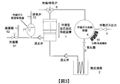
- FIG. 3 In the present invention, since the conversion of the aspect to kinetic energy is not required, it is not necessary to obtain the driving speed for the reciprocation, and the reciprocation may be a quasi-sexual motion.
- the self-pressurizing supply device in this figure is a method in which reciprocation is performed to pressurize the working gas raw fluid sequentially to reduce the pressure of the whole working gas container and to reduce the weight of the container.
- This device has a quasi-static operation, and thus, the propellant in the rocket, the power plant via the working gas, without converting the thermal energy applied to the heat exchanger into kinetic energy.
- -Water in the boiler becomes a pressure increase and supply device that acts as a pump.
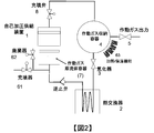
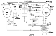
- FIG. 1 shows a rocket engine configuration with a thrust deflection controller using a static / reciprocal self-pressurizing feeder.
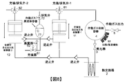
- FIG. 2 shows a multi-stage, reciprocating, self-pressurized delivery system, again using working gas exhaust for the delivery system.
- a reciprocating delivery system an example of the type of multistage delivery system that changes the phase of the reciprocating motion and suppresses the pulsation of the working gas pressure supplied.
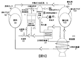
- a rocket type rocket that uses ethyl alcohol / nitrous oxide as fuel / oxidant, carbon dioxide gas as working gas, thrust deflection function, and cavitation prevention function at the time of liquefied carbon dioxide gas supply, rocket
- the figure which shows the example of implementation of an engine system.
- the most direct implementation is mounted on a rocket, configured with a combination of heat exchangers and vaporizers, pressurizing the tank containing the propellant (fuel and / or oxidant) and supplying propellant
- a heat exchanger for producing a working gas for forming a working gas is to constitute a device for pressurizing and supplying a raw fluid obtained by liquefying the mounted working gas by the obtained working gas itself. That is, the device not only performs self-pressurization but also has the function of supplying fluid while maintaining mass flow rate.
- the apparatus is referred to as a "self-pressurizing supply apparatus" including not only the pressure increase but also the function of supplying a fluid.
- This figure shows an example application to a rocket engine that uses a working gas to pressurize a propellant (fuel and / or oxidant) tank and introduce the propellant into a combustor.
- the heat source of the heat exchanger is obtained by being recovered from the combustor wall, thereby raising the temperature of the raw fluid.
- the working gas produced via the vaporizer is led to a self-pressurizing supply device and used by itself to pressurize the raw fluid. In the same device, it can be used without changing the condition of thermal energy in the boosting process, and constitutes a highly efficient supply system with a simple configuration.
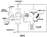
- This figure shows the application to a relatively small thrust thrust generator by injecting the obtained working gas itself out of the aircraft to obtain thrust.
- the apparatus and method of the present invention can realize the production process of supercritical fluid by this working gas itself, despite the simple structure. Boiling and bubble generation can be avoided, and a high heat exchange rate can be maintained.
- the working gas is preferably a nontoxic gas that can be loaded in a liquefied gas state and is inert, and a configuration that loads liquefied carbon dioxide gas, nitrous oxide, liquid nitrogen, and liquid helium is strong .
- kerosene As a propellant, kerosene, ethanol, liquefied natural gas, liquefied propane gas, liquid hydrogen, hydrazine, monomethylhydrazine etc. as fuel, and as an oxidant, liquid oxygen, nitrous oxide, tetranitrogen dioxide or nitric oxide mixed liquid
- oxidant liquid oxygen, nitrous oxide, tetranitrogen dioxide or nitric oxide mixed liquid
- the propellant especially the oxidant fluid can be pressurized to a high pressure, so thrust direction control to obtain lateral thrust by injecting it into the nozzle Can be applied to the configuration of the Since it is not necessary to separately carry the fluid for thrust direction deflection devices, and because the swing device of rocket engine combustors can be eliminated, simplification of the rocket system is promoted, leading to the configuration of a highly efficient rocket system. .
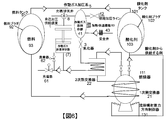
- the apparatus for suppressing bubble generation (cavitation) at the time of supplying liquefied gas is configured by maintaining the pressure exceeding the vapor pressure while keeping the liquefied gas container at the critical pressure or less. It is preferable that the working gas to be produced itself be combined with a device for pressurizing and supplying the liquefied gas, which is the source of the same gas, to the heat exchanger at a pressure exceeding the critical pressure, which is one of the preferred embodiments. ( Figure 7)
- the method shown in this figure is a method in which the raw fluid is pre-pressurized to a pressure that exceeds the vapor pressure, although the obtained working gas itself is below the critical pressure.
- the working gas to be exhausted is guided to the second self-pressurizing supply apparatus in which the area ratio is further increased at a lower pressure, and the supply is performed in multiple stages. It is a method to
- phase of the reciprocating motion of the self-pressurizing feeder with the same area ratio is changed in the same type of reciprocating self-pressurizing feeder, and 180 ° phase is horizontally opposed as an example to suppress the pulsation of the output pressure.
- An example of a self-pressurizing feeder that changes is shown. Since the number of times of supply per unit time can be increased, it contributes to the miniaturization of the device.
- the apparatus which pressure-supplys water or liquefied gas by the manufactured gas itself can be comprised.
- the power source for pressurized supply small and light, and being able to configure the pressurized supply system without changing the energy mode is a powerful embodiment.
Abstract
Description
特許公開2009-191611号公報「各種エネルギ保存サイクル合体機関」
特許公開2009-174318号公報「各種エネルギ保存サイクル合体機関」
タービンで、熱エネルギーを一旦運動エネルギーに変換するもので本発明とは全く異なる。
特許公開2005-147120号公報「各種エネルギ保存サイクル合体機関」
特許公開2005-146850号公報「各種ロケットエンジン合体機関」
推進剤の加給方式について触れていない。霧吹きでの吸気供給としており本発明とは全く異なる。
特許公開2005-002984号公報「各種竪型全動翼蒸気ガスタービン合体機関」
特許公開2005-002981号公報「各種全動翼蒸気ガスタービン合体機関」
タービンで、熱エネルギーを一旦運動エネルギーに変換するもので本発明とは全く異なる。
加圧供給方式を扱ったものではなく、本発明とは全く異なる。
タービンで、熱エネルギーを一旦運動エネルギーに変換するもので本発明とは全く異なる。
加圧供給方式を扱ったものではなく、本発明とは全く異なる。
特許公開2001-295612号公報「各種蒸気ガスタービン合体機関」
タービンで、熱エネルギーを一旦運動エネルギーに変換するもので本発明とは全く異なる。
加圧供給方式を扱ったものではなく、本発明とは全く異なる。
熱交換器壁面構造を扱ったもので、供給方式を扱ったものではなく、本発明とは全く異なる。
ロケットエンジンの加圧供給方式に関わるが、同発明での大前提は、加圧するガスを搭載していることであり、本発明と根本的に異なる。
特許公開2000-153416号公報「熱交換器組立装置」
これらの発明は、熱交換器製造装置に関わるもので、本発明とは対象がまったく異なる。
同発明では、「酸化剤、空気/炭化水素系の混合気によって作動する空気吸込み式内燃エンジンを備え、酸化剤及び燃料の供給が、ロケットエンジンの推進剤タンクから分離したタンク及び回路によって行われることを特徴とする装置」としており、本発明が行う、原流体である液状の不活性ガスを気化させて供給する方法とは全く異なる。
同発明は、加圧供給方式ではなく本発明とは全く異なる。
同発明は、オートバイエンジンの搭載形態に関したもので、本発明とは全く異なる。
同発明は、ノズル内面へのフィルム冷却を扱ったもので、本発明とはまったく異なる。
同発明は、燃焼室とノズルスカート部間の移行領域製造に関するもので、本発明の供給方式とはまったく異なる。
同発明は、燃焼室形成方法関するもので、本発明の供給方式とはまったく異なる。
同発明は、レーザー光の効率的な照射に関するもので、本発明の供給方式とはまったく異なる。
同発明で扱っているのは、ターボポンプを駆動した後の燃料ガスを燃焼器内で燃焼させることで、本発明の供給方式とはまったく異なる。
同発明は、ヘリウムでの冷却方法における押しガスを搭載する方式に関するもので、本発明の供給方式とはまったく異なる。
同発明は、再生冷却ノズルに関するもので、本発明の供給方式とはまったく異なる。
同発明は、機械式ポンプを用いるもので、本発明の供給方式とはまったく異なる。
ハイブリッドロケット関するものだが、供給方式に関するものではない。本発明の供給方式とはまったく異なる。
同発明は、スロートインサートに関するもので、本発明の供給方式とはまったく異なる。
同発明は、再生冷却器に関するもので、本発明の供給方式とはまったく異なる。
同発明は、機械式ポンプを有するエンジンを使ったもので、本発明の供給方式とはまったく異なる。
同発明は、再生冷却器そのものに関するもので、本発明の供給方式とはまったく異なる。
同発明は、機械式ポンプを用いたもので、本発明の供給方式とはまったく異なる。
同発明は、蒸着器を扱ったもので、本発明の供給方式とはまったく異なる。
同発明は、酸化剤を熱交換させて発生したガスで、機械式ポンプを駆動するモーターを駆動させる方法を述べており、本発明の供給方式とはまったく異なる。
同発明では、加圧体(pressurant) で、ピストンを駆動し、推進剤(propellant) を供給する、昇圧・供給機が請求されている。一見、往復のピストンは、本発明での1つの請求と類似に見える。しかし、同発明での昇圧・供給機とは推進剤を供給するものであり、本発明で扱っている供給器では、供給するものは推進剤(燃料、酸化剤)を収容する容器(タンク)を加圧する加圧体(pressurant)であって推進剤ではなく、想定するエンジンシステムそのものが根本的に異なっている。また、本発明でいう逐次型の昇圧・供給機(チャージャー)の最大の特徴は、加圧体(pressurant) そのものを供給機から吐出される流体から生成される蒸気であることにある。すなわち、作動ガス自身にて昇圧し供給することを特徴としており、同発明では開示されていない。また、本発明では、加圧体(pressurant) が低圧であっても、ピストンの面積比を変えて、昇圧できることを利用しているが、この点も同発明では開示されていない。したがって、本発明は同発明と根本的に異なる。
同発明は、機械式ポンプにおけるキャビテーションを扱ったもので、本発明の供給方式とはまったく異なる。
同発明の題名は、ガスの収容供給方式であるが、超臨界流体として液体ヘリウムを用いて、その状態でガスを保持し、熱交換器使って、ガスを得て供給する方式を請求している。とくにロケットへの請求については、同文献では、
26. A method of providing a source of pressurized gas aboard a rocket powered launch vehicle, comprising the steps of: providing a storage bottle which is configured to receive and hold a stored gas at a predetermined pressurization and includes an internally mounted heating device configured to transfer heat to the stored gas; preparing the storage bottle for receiving an amount of the stored gas; pumping stored gas into the bottle from a remotely located source at a predetermined temperature until a desired pressure are attained; allowing amounts of the stored gas to exit the bottle to be directed to at least one remote location; and as the stored gas exits the bottle, employing the internally mounted heating device to control temperature of the stored gas to affect pressure of the stored gas.
27. The method of claim 26 wherein the stored gas is supercritical helium at a density of at least 7 lbs/ft.sup.3.
と記述されている。
この内容は、加圧ガスを液体として搭載し、それをロケット機上で得られる熱を熱交換器を介して取り出し、所望の圧力のガス得ようというもので、このコンセプト自体は、専門家であれば容易に到達しうる概念で、この点を、本発明でも背景として述べている。
同発明では、予め、超臨界液体ヘリウムを収納した容器の存在を前提としている。したがって、超臨界流体を得るための昇圧する仕組みを明らかにしていない。本発明では、この昇圧を自らが生成して供給した低圧のガスから行うことを特徴としている。本発明とは全く異なる。
米国特許第20100326044号明細書「METHOD FOR COOLING ROCKET ENGINES」
米国特許第20100218482号明細書「SYSTEM AND METHOD FOR COOLING ROCKET ENGINES」
これらの発明は、熱交換器を用いて、推進剤の加圧に役立てる点では共通するが、これらの発明では、結果として、推進剤を推進剤からのガスで加圧する方式を請求している。本発明では、熱交換器で原流体から生成される不活性ガスを推進剤の加圧体(pressurant) に用いている点、および同加圧体(pressurant) 自身で昇圧し供給する方式の採用を請求しており、根本的に異なるものである。
同発明では、加圧供給方式に言及しておらず、本発明とはまったく異なる。
同発明は、機械式ポンプに関するもので、本発明の供給方式とはまったく異なる。
同発明は、機械式ポンプによる供給に関するものであり、本発明の供給方式とはまったく異なる。
同発明は、機械式ポンプによる供給に関するものであり、本発明の供給方式とはまったく異なる。
同発明は、機械式ポンプによる供給に関するものであり、本発明の供給方式とはまったく異なる。
同発明では、酸化剤を超臨界状態にもっていくとしており、沸騰を抑えることが目的であると記述されており、この点については、解決をはかる課題の一部が本発明と共通である。しかし、機械式の供給手段が請求されており、本発明の供給方式とはまったく異なる。
この方式によって、軽量化と耐久性の大幅な向上をはかることができる。
2 あるいは 21, 22 : 熱交換器。
3 : 気化器。
4 あるいは 41 : 作動ガス収納容器。
42, 43 : 初期加圧ポート、安全弁。
5 : 作動ガス出力ポート。あるいは、作動ガスを用いた推進剤の加圧系統。
61, 62, 63 : 補助付随要素。61 は、充填器、 62 は、廃棄器、63 は、作動ガス収納容器の保温/加温機能。
7 あるいは 71 : 作動ガス原流体収納容器。
72 作動ガス原流体蒸気の排気ポート。
8 あるいは、81, 82 : 作動ガスを自己加圧供給装置に向ける、あるいは自己加圧供給装置から排気するために、充填/排気弁。
91, 92, 93 : 燃料タンク、燃料用ブラダ、燃料流体。
101,102, 103 : 燃料タンク、燃料用ブラダ、燃料流体。
111 : 燃焼器。
121 : 作動ガス噴射器。推力発生器。
131 : 流体噴射推力方向制御器。
Claims (29)
- 圧力差を利用して流体を輸送する過程たる加圧供給を目的として、同過程の昇圧を担う気体を、同気体の材料たる原流体を気化させることによって製造する装置であって、熱源および熱交換器と気化器と組合せて構成され、熱交換後の好ましくは超臨界状態に昇圧された流体を気化器で減圧することで製造された同加圧供給を担う気体自身が、同原流体との密度差を利用して、同原流体を、質量流量を確保しつつも同時に昇圧して、熱交換器へと供給する装置。
- 前記請求項1 における原流体を液化して容器に収容する形式においては、同容器を蒸気圧を超える圧力に維持し、気泡の発生を抑制させつつ、同原流体を請求項1 の装置に供給する補助装置。
- 前記請求項 1において、昇圧過程を担う気体側を低圧側とし、熱交換器への入力側を高圧側とし、同気体のエネルギー様態を運動エネルギーないしは電気エネルギーへ変換することを動力源の確保に要しない、機械式の吐出装置にて昇圧することを特徴とする、請求項1および2の装置。
- 前記請求項 1において、昇圧過程を担う気体側を大口径側とし、熱交換器への入力側を小口径側とした、口径の異なるピストンを設けて昇圧することを特徴とする、請求項1ないし 3の装置。
- 前記請求項4において、ピストンを往復運動させることにより、加圧供給を担う気体の材料である原流体を、逐次的に昇圧することを特徴とする、請求項4の装置。
- 前記請求項 5において、装置より排出される低圧のガスを用いて、さらに口径比を高めたピストンを用いて多段の昇圧を行う、請求項5の装置。
- 前記請求項 5において、ピストンの往復運動の位相を変え、供給する圧力の脈動を抑制することを目的に、並列にピストンを用いて昇圧を行う、請求項5ないし6の装置。
- 燃料や酸化剤の両方ないしいずれかの推進剤を収容する容器を加圧し、同推進剤を圧力差を利用して燃焼器ないし推力発生機構へと輸送する過程たる加圧供給を目的として、同加圧過程の昇圧を担う気体を、同気体の材料たる原流体を気化させることによって製造する装置であって、同燃焼器ないし同推力発生機構からの余剰熱源あるいは搭載される別の熱源および熱交換器と気化器と組合せて構成され、熱交換後の好ましくは超臨界状態に昇圧された流体を気化器で減圧することで製造された同加圧供給を担う気体自身が、同原流体との密度差を利用して、同原流体を質量流量を確保しつつも同時に昇圧して、熱交換器へと供給する装置を用いることを特徴とする、ロケットエンジン。
- 前記請求項 8 において、原流体を液化して容器に収容する形式においては、同収容容器を蒸気圧を超える圧力に維持し、気泡の発生を抑制させつつ、同原流体を請求項8 の装置に供給する補助装置を同時に装備することを特徴とする、ロケットエンジン。
- 前記請求項 8において、燃料や酸化剤の両方ないしいずれかの推進剤を収納する容器を加圧する過程で、同推進剤を材料適合性の要件を満たす袋(ブラダ)にて収容させ、前記請求項 8 における加圧供給の昇圧を担う気体にて同ブラダを圧縮して、加圧供給系を構成することを特徴とする、請求項 8ないし9記載のロケットエンジン。
- 前記請求項 8において、加圧供給の昇圧を担う気体そのもの、ないしは加圧供給される液相ないし気相の推進剤たる燃料あるいは酸化剤を、燃焼器ないし推力発生機構出口のノズル内に噴射させて、推進剤の供給に併せて、推力方向の制御を同時に行わせることを特徴とする、請求項 8ないし10記載のロケットエンジン。
- 前記請求項 8 において、昇圧過程を担う気体側を低圧側とし、熱交換器への入力側を高圧側とした、同気体のエネルギー様態を運動エネルギーないしは電気エネルギーへ変換することを要しない、機械式の吐出装置にて昇圧することを特徴とする、請求項 8ないし11記載のロケットエンジン。
- 前記請求項 8 において、昇圧過程を担う気体側を大口径側とし、熱交換器への入力側を小口径側とした、口径の異なるピストンを設けて昇圧することを特徴とする、請求項 8ないし11記載のロケットエンジン。
- 前記請求項13において、ピストンの往復運動により、加圧供給の昇圧を担う気体の材料である原流体を、逐次的に昇圧することを特徴とする、請求項 8ないし11記載のロケットエンジン。
- 前記請求項 14において、装置より排出される低圧のガスを用いて、さらに口径比を高めたピストンを用いて多段の昇圧を行うことを特徴とする、請求項 8ないし11記載のロケットエンジン。
- 前記請求項 14において、ピストンの往復運動の位相を変え、供給する圧力の脈動を抑制することを目的に、並列にピストンを用いて昇圧を行うことを特徴とする、請求項 8ないし11記載のロケットエンジン。
- 高圧の気体を容器に貯蔵することを目的として、同貯蔵されるべき気体を、同気体の材料たる原流体を気化させることによって製造する装置であって、熱源および熱交換器と気化器と組合せて構成され、熱交換後の好ましくは超臨界状態に昇圧された流体を気化器で減圧することで製造された同貯蔵されるべき気体自身が、同原流体との密度差を利用して、同原流体を質量流量を確保しつつも同時に昇圧して、熱交換器へ供給する装置。
- 前記請求項 17 において、貯蔵される気体を得て、機体外部に同気体を噴射させて反力を得ることを目的として、前記請求項 17 の装置を用いる、ロケット、人工衛星、宇宙探査機に搭載する、気体噴射型の姿勢ないしは軌道制御装置。
- 前記請求項 18において、前記請求項 17 の原流体を収納する容器を加圧する過程で、貯蔵される気体の材料である原流体を材料適合性の要件を満たす袋(ブラダ)にて収容させ、同貯蔵される気体にて同ブラダを圧縮して、同原流体を熱交換機へ供給することを特徴とする、請求項 18記載の姿勢ないしは軌道制御装置。
- 前記請求項 17において、昇圧過程で、貯蔵される気体側を低圧側とし、熱交換器への入力側を高圧側とした、同気体のエネルギー様態を運動エネルギーないしは電気エネルギーへ変換することを要しない、機械式の吐出装置にて昇圧することを特徴とする、請求項 18ないし19の姿勢ないしは軌道制御装置。
- 前記請求項 17 において、昇圧過程で、貯蔵される気体側を大口径側とし、熱交換器への入力側を小口径側とした、口径の異なるピストンを設けて昇圧することを特徴とする、請求項 18ないし19の姿勢ないしは軌道制御装置。
- 前記請求項21において、ピストンの往復運動により、前記請求項 17 の貯蔵される気体側の材料たる原流体を、逐次的に昇圧することを特徴とする、請求項 18ないし19の姿勢ないしは軌道制御装置。
- 前記請求項 22において、装置より排出される低圧の気体を用いて、さらに口径比を高めたピストンを用いて多段の昇圧を行う、請求項22の装置を用いることを特徴とする、請求項 18ないし19の姿勢ないしは軌道制御装置。
- 前記請求項 22において、ピストンの往復運動の位相を変え、供給する圧力の脈動を抑制することを目的に、並列にピストンを用いて昇圧を行うことを特徴とする、請求項 18ないし19の姿勢ないしは軌道制御装置。
- 発電所、ボイラーにおいて、前記請求項 1 における加圧供給過程の昇圧を担う気体の原材料を水ないしは液化ガスをとする、請求項1に記載の装置。
- 船舶、車輌において、前記請求項 1 における加圧供給過程の昇圧を担う気体の製造を行う、請求項1に記載の装置。
- 圧力差を利用して輸送する過程たる加圧供給を目的として、同加圧供給過程の昇圧を担う気体を、同気体の材料たる原流体を気化させることによって製造する方法であって、熱源および熱交換器と気化器と組合わされ、熱交換後の好ましくは超臨界状態に昇圧された流体を気化器で減圧することで製造された同加圧供給を担う気体自身が、同原流体との密度差を利用して、同原流体を、質量流量を確保しつつも同時に昇圧して、熱交換器へと供給する方法。
- 燃料や酸化剤の両方ないしいずれかの推進剤を収容する容器を加圧し、同推進剤を圧力差を利用して燃焼器ないし推力発生機構へと輸送する過程たる加圧供給を目的として、同加圧供給過程の昇圧を担う気体を、同気体の材料たる原流体を気化させることによって製造する方法であって、同燃焼器ないし同推力発生機構からの余剰熱源あるいは搭載される別の熱源および熱交換器と気化器と組合わされ、熱交換後の好ましくは超臨界状態に昇圧された流体を気化器で減圧することで製造された同加圧供給を担う気体自身が、同原流体との密度差を利用して、同原流体を質量流量を確保しつつも同時に昇圧して、熱交換器へと供給する方法を用いることを特徴とする、ロケットエンジン。
- 高圧の気体を容器に貯蔵することを目的として、同貯蔵されるべき気体を、同気体の材料たる原流体を気化させることによって製造する方法であって、熱源および熱交換器と気化器と組合わされ、熱交換後の好ましくは超臨界状態に昇圧された流体を気化器で減圧することで製造された同貯蔵されるべき気体自身が、同原流体との密度差を利用して、同原流体を質量流量を確保しつつも同時に昇圧して、熱交換器へ供給する方法。
Priority Applications (5)
| Application Number | Priority Date | Filing Date | Title |
|---|---|---|---|
| US15/322,294 US10605203B2 (en) | 2014-09-25 | 2014-09-25 | Device, system, and method for pressurizing and supplying fluid |
| CN201480082137.4A CN107076055B (zh) | 2014-09-25 | 2014-09-25 | 流体加压供给装置、系统以及方法 |
| JP2016549829A JP6289652B2 (ja) | 2014-09-25 | 2014-09-25 | 流体を加圧し供給する装置、システム、および方法。 |
| PCT/JP2014/075333 WO2016046924A1 (ja) | 2014-09-25 | 2014-09-25 | 流体を加圧し供給する装置、システム、および方法。 |
| EP14902357.4A EP3199792B1 (en) | 2014-09-25 | 2014-09-25 | Device and method for pressurizing and supplying fluid |
Applications Claiming Priority (1)
| Application Number | Priority Date | Filing Date | Title |
|---|---|---|---|
| PCT/JP2014/075333 WO2016046924A1 (ja) | 2014-09-25 | 2014-09-25 | 流体を加圧し供給する装置、システム、および方法。 |
Publications (1)
| Publication Number | Publication Date |
|---|---|
| WO2016046924A1 true WO2016046924A1 (ja) | 2016-03-31 |
Family
ID=55580485
Family Applications (1)
| Application Number | Title | Priority Date | Filing Date |
|---|---|---|---|
| PCT/JP2014/075333 WO2016046924A1 (ja) | 2014-09-25 | 2014-09-25 | 流体を加圧し供給する装置、システム、および方法。 |
Country Status (5)
| Country | Link |
|---|---|
| US (1) | US10605203B2 (ja) |
| EP (1) | EP3199792B1 (ja) |
| JP (1) | JP6289652B2 (ja) |
| CN (1) | CN107076055B (ja) |
| WO (1) | WO2016046924A1 (ja) |
Cited By (1)
| Publication number | Priority date | Publication date | Assignee | Title |
|---|---|---|---|---|
| CN112228765A (zh) * | 2020-09-30 | 2021-01-15 | 西安交通大学 | 低温火箭发射场中深度过冷液氧加注与控制系统及方法 |
Families Citing this family (6)
| Publication number | Priority date | Publication date | Assignee | Title |
|---|---|---|---|---|
| FR3009585A1 (fr) * | 2013-08-06 | 2015-02-13 | Snecma | Dispositif de pressurisation d'un reservoir d'ergol d'un moteur de fusee |
| US11073169B2 (en) * | 2018-06-26 | 2021-07-27 | Energy Recovery, Inc. | Power generation system with rotary liquid piston compressor for transcritical and supercritical compression of fluids |
| US10704696B2 (en) * | 2018-10-26 | 2020-07-07 | Hamilton Sunstrand Corporation | Fluid transportation system |
| CN109826725A (zh) * | 2019-02-19 | 2019-05-31 | 北京星际荣耀空间科技有限公司 | 推进系统的动力机构、推进系统及液体火箭系统 |
| DE102019123057A1 (de) | 2019-08-28 | 2021-03-04 | Deutsches Zentrum für Luft- und Raumfahrt e.V. | Antriebssystem für ein Raumfahrzeug und Verfahren zum Betreiben eines Raumfahrzeugs |
| US11397030B2 (en) * | 2020-07-10 | 2022-07-26 | Energy Recovery, Inc. | Low energy consumption refrigeration system with a rotary pressure exchanger replacing the bulk flow compressor and the high pressure expansion valve |
Citations (7)
| Publication number | Priority date | Publication date | Assignee | Title |
|---|---|---|---|---|
| US4583362A (en) * | 1983-12-12 | 1986-04-22 | Rockwell International Corporation | Expander-cycle, turbine-drive, regenerative rocket engine |
| JP2000248994A (ja) * | 1999-03-01 | 2000-09-12 | Ishikawajima Harima Heavy Ind Co Ltd | ロケットエンジンの推薬加圧装置 |
| US20030005708A1 (en) * | 2001-05-22 | 2003-01-09 | Philip Beck | Airborne gas storage and supply system |
| US20040148925A1 (en) * | 2002-08-09 | 2004-08-05 | Knight Andrew F. | Pressurizer for a rocket engine |
| JP2008240643A (ja) * | 2007-03-27 | 2008-10-09 | Hokkaido Univ | バルブレス液体供給装置 |
| US20100326044A1 (en) * | 2006-08-25 | 2010-12-30 | Xcor Aerospace | Method for cooling rocket engines |
| US20110005193A1 (en) * | 2009-07-07 | 2011-01-13 | Thomas Clayton Pavia | Method and apparatus for simplified thrust chamber configurations |
Family Cites Families (50)
| Publication number | Priority date | Publication date | Assignee | Title |
|---|---|---|---|---|
| US5219270A (en) | 1991-08-22 | 1993-06-15 | Titmas And Associates Incorporated | Reaction barrel with rocket nozzles in staggered alignment and connecting ducts of unequal length |
| US5222873A (en) | 1992-06-19 | 1993-06-29 | The United States Of America As Represented By The United States Department Of Energy | Fluid-driven reciprocating apparatus and valving for controlling same |
| US5644920A (en) * | 1995-09-25 | 1997-07-08 | Rockwell International Corporation | Liquid propellant densification |
| US5802842A (en) | 1996-07-29 | 1998-09-08 | Trw Inc. | Dimensionally stable throat insert for rocket thrusters |
| JP3942230B2 (ja) | 1997-04-14 | 2007-07-11 | 秋 葉 鐐二郎 | ロケットエンジン |
| JPH11229963A (ja) | 1998-02-12 | 1999-08-24 | Ishikawajima Harima Heavy Ind Co Ltd | 液体ロケットエンジンにおけるエキスパンダサイクル構造 |
| AU4568399A (en) | 1998-06-15 | 2000-01-05 | Lockheed Martin Corporation | Electrical drive system for rocket engine propellant pumps |
| KR100367717B1 (ko) | 1998-11-18 | 2003-04-10 | 한라공조주식회사 | 열교환기조립장치 |
| US6467253B1 (en) | 1998-11-27 | 2002-10-22 | Volvo Aero Corporation | Nozzle structure for rocket nozzles having cooled nozzle wall |
| KR100590787B1 (ko) | 1998-12-11 | 2006-08-30 | 한라공조주식회사 | 열교환기 조립장치 |
| DE19915082C1 (de) | 1999-04-01 | 2000-07-13 | Daimler Chrysler Ag | Verfahren zur Herstellung einer gekühlten Düse für ein Raketentriebwerk |
| JP4405630B2 (ja) | 1999-11-12 | 2010-01-27 | 株式会社Ihiエアロスペース | 液体ロケットエンジンシステムの冷却構成及びその冷却方法 |
| JP2001207912A (ja) | 2000-01-20 | 2001-08-03 | Ishikawajima Harima Heavy Ind Co Ltd | ロケットエンジンの運転方法及びそれを用いるロケットエンジン |
| JP2001295612A (ja) | 2000-02-10 | 2001-10-26 | Hiroyasu Tanigawa | 各種蒸気ガスタービン合体機関 |
| JP2002195151A (ja) | 2000-12-26 | 2002-07-10 | Ishikawajima Harima Heavy Ind Co Ltd | プラズマガス推進装置 |
| US7257940B1 (en) | 2001-06-12 | 2007-08-21 | Knight Andrew F | Device and method for pumping a fluid |
| US6499288B1 (en) | 2001-06-12 | 2002-12-31 | Andrew F. Knight | Pressurizer for a rocket engine |
| US7194853B1 (en) | 2001-06-12 | 2007-03-27 | Knight Andrew F | Pressurizer for a rocket engine |
| JP3870252B2 (ja) | 2001-07-19 | 2007-01-17 | 独立行政法人 宇宙航空研究開発機構 | キャビテーション抑制ポンプシステム |
| JP2004100678A (ja) | 2002-01-22 | 2004-04-02 | Hiroyasu Tanigawa | 各種全動翼蒸気ガスタービン合体機関 |
| AU2002334177A1 (en) | 2002-06-07 | 2004-02-09 | Brumby Corporation Limited | Motorcycle engine |
| JP2004332541A (ja) | 2002-10-17 | 2004-11-25 | Hiroyasu Tanigawa | 各種エネルギ保存サイクル機関 |
| JP2004332539A (ja) | 2002-10-17 | 2004-11-25 | Hiroyasu Tanigawa | 各種エネルギ保存サイクル機関 |
| JP2004332540A (ja) | 2003-01-09 | 2004-11-25 | Hiroyasu Tanigawa | 各種全動翼蒸気ガスタービン合体機関 |
| JP2005002981A (ja) | 2003-01-09 | 2005-01-06 | Hiroyasu Tanigawa | 各種全動翼蒸気ガスタービン合体機関 |
| JP2005002984A (ja) | 2003-01-09 | 2005-01-06 | Hiroyasu Tanigawa | 各種竪型全動翼蒸気ガスタービン合体機関 |
| JP2005113683A (ja) | 2003-01-09 | 2005-04-28 | Hiroyasu Tanigawa | 各種全動翼蒸気ガスタービン合体機関 |
| FR2850741B1 (fr) | 2003-01-30 | 2005-09-23 | Snecma Propulsion Solide | Procede de fabrication d'un panneau de refroidissement actif en materiau composite thermostructural |
| US7051513B2 (en) | 2003-06-06 | 2006-05-30 | United Technologies Corporation | Rocket engine tubular chamber with single piece jacket |
| US7213392B2 (en) | 2003-06-10 | 2007-05-08 | United Technologies Corporation | Rocket engine combustion chamber |
| JP2005147122A (ja) | 2003-10-09 | 2005-06-09 | Hiroyasu Tanigawa | 各種ロケット合体機関 |
| JP2005147120A (ja) | 2003-10-09 | 2005-06-09 | Hiroyasu Tanigawa | 各種エネルギ保存サイクル合体機関 |
| JP2005146850A (ja) | 2003-10-09 | 2005-06-09 | Hiroyasu Tanigawa | 各種ロケットエンジン合体機関 |
| US7790003B2 (en) | 2004-10-12 | 2010-09-07 | Southwest Research Institute | Method for magnetron sputter deposition |
| CN100480488C (zh) | 2004-12-28 | 2009-04-22 | 蒋子刚 | 流体机械的揉动变容方法及其机构与用途 |
| US20070007879A1 (en) | 2005-07-11 | 2007-01-11 | Bergman Thomas J Jr | Low vapor pressure gas delivery system and apparatus |
| JP4764160B2 (ja) | 2005-12-21 | 2011-08-31 | 株式会社東芝 | 半導体装置 |
| JP2007332335A (ja) | 2006-06-10 | 2007-12-27 | Shinichiro Kojima | 廃ゴム類全般、廃タイヤ、全自動油化、油分、抽出、コークス成製装置 |
| KR100674118B1 (ko) | 2006-07-07 | 2007-01-24 | (주)씨앤스페이스 | 로켓 추진용 메탄엔진 |
| US20080016846A1 (en) | 2006-07-18 | 2008-01-24 | United Technologies Corporation | System and method for cooling hydrocarbon-fueled rocket engines |
| US7784268B1 (en) | 2006-08-04 | 2010-08-31 | Xcor Aerospace | Partial superheat cycle for operating a pump in a rocket system |
| JP2009174316A (ja) | 2006-09-26 | 2009-08-06 | Hiroyasu Tanigawa | 各種エネルギ保存サイクル合体機関 |
| US20100096491A1 (en) | 2006-10-02 | 2010-04-22 | Rocket Racing, Inc. | Rocket-powered entertainment vehicle |
| US7900436B2 (en) | 2007-07-20 | 2011-03-08 | The United States Of America As Represented By The Administrator Of The National Aeronautics And Space Administration | Gas-generator augmented expander cycle rocket engine |
| JP2009191611A (ja) | 2007-09-13 | 2009-08-27 | Hiroyasu Tanigawa | 各種エネルギ保存サイクル合体機関 |
| FR2921979B1 (fr) | 2007-10-08 | 2014-06-13 | Astrium Sas | Dispositif et procede de motorisation de pompe pour moteur fusee par moteur a combustion interne |
| AU2009324696A1 (en) | 2008-12-08 | 2011-07-21 | Firestar Engineering, Llc | Regeneratively cooled porous media jacket |
| US8266884B1 (en) * | 2009-03-04 | 2012-09-18 | Mark Baker | Asynchronous combustion system |
| US8943795B2 (en) | 2009-09-08 | 2015-02-03 | Ihi Corporation | Rocket engine system for realizing high-speed response |
| JP5666353B2 (ja) | 2011-03-11 | 2015-02-12 | 株式会社Ihiエアロスペース | 液体ロケットエンジン用ノズル |
-
2014
- 2014-09-25 JP JP2016549829A patent/JP6289652B2/ja active Active
- 2014-09-25 US US15/322,294 patent/US10605203B2/en active Active
- 2014-09-25 EP EP14902357.4A patent/EP3199792B1/en active Active
- 2014-09-25 CN CN201480082137.4A patent/CN107076055B/zh active Active
- 2014-09-25 WO PCT/JP2014/075333 patent/WO2016046924A1/ja active Application Filing
Patent Citations (7)
| Publication number | Priority date | Publication date | Assignee | Title |
|---|---|---|---|---|
| US4583362A (en) * | 1983-12-12 | 1986-04-22 | Rockwell International Corporation | Expander-cycle, turbine-drive, regenerative rocket engine |
| JP2000248994A (ja) * | 1999-03-01 | 2000-09-12 | Ishikawajima Harima Heavy Ind Co Ltd | ロケットエンジンの推薬加圧装置 |
| US20030005708A1 (en) * | 2001-05-22 | 2003-01-09 | Philip Beck | Airborne gas storage and supply system |
| US20040148925A1 (en) * | 2002-08-09 | 2004-08-05 | Knight Andrew F. | Pressurizer for a rocket engine |
| US20100326044A1 (en) * | 2006-08-25 | 2010-12-30 | Xcor Aerospace | Method for cooling rocket engines |
| JP2008240643A (ja) * | 2007-03-27 | 2008-10-09 | Hokkaido Univ | バルブレス液体供給装置 |
| US20110005193A1 (en) * | 2009-07-07 | 2011-01-13 | Thomas Clayton Pavia | Method and apparatus for simplified thrust chamber configurations |
Cited By (2)
| Publication number | Priority date | Publication date | Assignee | Title |
|---|---|---|---|---|
| CN112228765A (zh) * | 2020-09-30 | 2021-01-15 | 西安交通大学 | 低温火箭发射场中深度过冷液氧加注与控制系统及方法 |
| CN112228765B (zh) * | 2020-09-30 | 2021-07-09 | 西安交通大学 | 低温火箭发射场中深度过冷液氧加注与控制系统及方法 |
Also Published As
| Publication number | Publication date |
|---|---|
| CN107076055A (zh) | 2017-08-18 |
| US20170167442A1 (en) | 2017-06-15 |
| US10605203B2 (en) | 2020-03-31 |
| EP3199792A4 (en) | 2018-05-30 |
| JP6289652B2 (ja) | 2018-03-07 |
| CN107076055B (zh) | 2018-11-02 |
| JPWO2016046924A1 (ja) | 2017-08-17 |
| EP3199792B1 (en) | 2021-02-24 |
| EP3199792A1 (en) | 2017-08-02 |
Similar Documents
| Publication | Publication Date | Title |
|---|---|---|
| WO2016046924A1 (ja) | 流体を加圧し供給する装置、システム、および方法。 | |
| US10844808B2 (en) | Rocket engine systems with an independently regulated cooling system | |
| US11181076B2 (en) | Rocket engine bipropellant supply system including an electrolyzer | |
| US20180238272A1 (en) | Tri-propellant rocket engine for space launch applications | |
| US8572948B1 (en) | Rocket engine propulsion system | |
| JP6836303B2 (ja) | ターボジェットおよびターボプロップ複合エンジン | |
| JP2016510376A (ja) | 航空機において燃料を供給するための極低温燃料システム及び方法 | |
| US20220412263A1 (en) | Engine using heated and turbo-expanded ammonia fuel | |
| US10309344B2 (en) | Stored pressure driven cycle | |
| JP2016509550A (ja) | 航空機及び組み込み式極低温燃料システム | |
| JP6308567B2 (ja) | ロケットエンジンへの供給方法および供給装置 | |
| US20180171933A1 (en) | Micropump-fed autogenous pressurization system | |
| JP2013540941A (ja) | 二元燃料航空機エンジン制御システム及びその運転方法 | |
| JP2016509549A (ja) | 航空機発電システム及び方法 | |
| JP2016503858A (ja) | タービンエンジン組立体及び二元燃料航空機システム | |
| US10371098B2 (en) | Device for pressurizing a propellant tank of a rocket engine | |
| US5129599A (en) | Hybrid liquid-vapor propellant feed system for aerospace vehicles | |
| JP2016508912A (ja) | Lngボイルオフを管理する方法及びlngボイルオフの管理組立体 | |
| RU2447313C1 (ru) | Жидкостный ракетный двигатель многократного включения (варианты) | |
| EP2761159B1 (en) | Propulsion system | |
| Zegler | An integrated vehicle propulsion and power system for long duration cryogenic spaceflight | |
| WO2023053207A1 (ja) | 宇宙機搭載の推進装置 | |
| CN215949674U (zh) | 一种液体火箭贮箱电热增压系统 | |
| US20230399120A1 (en) | Aircraft system, aircraft fuel system and method | |
| CN117190801A (zh) | 姿控动力系统和运载火箭 |
Legal Events
| Date | Code | Title | Description |
|---|---|---|---|
| 121 | Ep: the epo has been informed by wipo that ep was designated in this application |
Ref document number: 14902357 Country of ref document: EP Kind code of ref document: A1 |
|
| REEP | Request for entry into the european phase |
Ref document number: 2014902357 Country of ref document: EP |
|
| ENP | Entry into the national phase |
Ref document number: 2016549829 Country of ref document: JP Kind code of ref document: A |
|
| WWE | Wipo information: entry into national phase |
Ref document number: 15322294 Country of ref document: US |
|
| NENP | Non-entry into the national phase |
Ref country code: DE |