WO2016043325A1 - Dispositif de pesage associatif - Google Patents
Dispositif de pesage associatif Download PDFInfo
- Publication number
- WO2016043325A1 WO2016043325A1 PCT/JP2015/076776 JP2015076776W WO2016043325A1 WO 2016043325 A1 WO2016043325 A1 WO 2016043325A1 JP 2015076776 W JP2015076776 W JP 2015076776W WO 2016043325 A1 WO2016043325 A1 WO 2016043325A1
- Authority
- WO
- WIPO (PCT)
- Prior art keywords
- frame
- main body
- weighing device
- weighing
- support frame
- Prior art date
Links
Images


Classifications
-
- G—PHYSICS
- G01—MEASURING; TESTING
- G01G—WEIGHING
- G01G19/00—Weighing apparatus or methods adapted for special purposes not provided for in the preceding groups
- G01G19/387—Weighing apparatus or methods adapted for special purposes not provided for in the preceding groups for combinatorial weighing, i.e. selecting a combination of articles whose total weight or number is closest to a desired value
- G01G19/393—Weighing apparatus or methods adapted for special purposes not provided for in the preceding groups for combinatorial weighing, i.e. selecting a combination of articles whose total weight or number is closest to a desired value using two or more weighing units
Definitions
- the present invention relates to a combination weighing device.
- a combination weighing device described in Patent Document 1 As a conventional combination weighing device, for example, a combination weighing device described in Patent Document 1 is known.
- the combination weighing device described in Patent Document 1 includes a dispersion supply unit that supplies and supplies the objects to be distributed to the surroundings, and a plurality of circumferences arranged around the distribution supply unit. And a plurality of hoppers that drop and discharge, and a collecting chute that is disposed below the hopper and collects and discharges the discharged objects to be weighed.
- the distributed supply unit, the plurality of hoppers, and the collecting chute are attached to the main body, and the main body is supported by a columnar column.
- the above-mentioned combination weighing apparatus often targets foods and other items that should be considered in terms of hygiene, and the apparatus is cleaned at the place where the apparatus is installed.
- the combination weighing device is desired to have a structure in which cleaning water or the like does not accumulate in the device.
- the object of the present invention is to provide a combination weighing device excellent in hygiene.
- a combination weighing device is a combination weighing device including a plurality of weighing mechanisms, a weighing mechanism frame that accommodates the weighing mechanism, and a main body frame that supports the weighing mechanism frame.
- the normal of one surface is inclined with respect to the vertical direction.
- the normal of one surface of the main body frame is inclined with respect to the vertical direction. Therefore, since one surface of the main body frame is inclined, cleaning water or the like attached to the one surface is likely to fall. Therefore, it is possible to suppress cleaning water and the like from accumulating on one surface of the main body frame. As a result, the combination weighing device is excellent in hygiene.
- the main body frame is configured by a plane, and the normal of the upper surface and / or the lower surface of the main body frame may be inclined with respect to the vertical direction. Accordingly, since the upper surface and / or the lower surface of the main body frame is inclined, the cleaning water or the like adhering to the upper surface and / or the lower surface easily falls, and the cleaning water or the like does not accumulate on the upper surface and / or the lower surface. Therefore, the combination weighing device is excellent in hygiene.
- the normal of the upper surface and / or the lower surface of the main body frame is inclined outward or inward of the main body frame with respect to the vertical direction.
- the upper and lower surfaces of the main body frame are moved from the inner side to the outer side of the main body frame. Inclined downward. Therefore, cleaning water or the like adhering to the main body frame is guided to the outside of the combination weighing device. Therefore, it is possible to prevent washing and the like from dropping immediately below the combination weighing device, and to realize a combination weighing device excellent in hygiene.
- the vertical dimension of the main body frame is larger than the horizontal dimension.
- the rigidity of the main body frame in the vertical direction is increased. Accordingly, it is possible to effectively suppress disturbances such as floor vibrations and vibrations caused by the device itself. As a result, the influence of disturbance or the like on the measuring mechanism can be suppressed, and the measuring accuracy in the measuring mechanism can be improved.
- the main body frame has a laterally extending member that extends laterally, and the normal line of the upper surface and / or the lower surface in the longitudinal section of the laterally extending member may be inclined with respect to the vertical direction.
- the normal line of the upper surface and / or the lower surface of the laterally extending member may be inclined outward or inward of the main body frame with respect to the vertical direction.
- the normal of the upper surface is inclined to the outside of the main body frame with respect to the vertical direction
- the normal of the lower surface is inclined to the inner side of the main body frame with respect to the vertical direction
- the upper and lower surfaces of the laterally extending members are outside from the inner side of the main body frame. Inclined downward toward Therefore, the washing water or the like adhering to the laterally stretched member is guided to the outside of the combination weighing device. Therefore, it is possible to prevent the washing water or the like from dropping immediately below the combination weighing device, and it is possible to realize a combination weighing device excellent in hygiene.
- the longitudinal section of the laterally stretched member may be a quadrangular shape that extends long in the vertical direction. Since the laterally extending member has a quadrangular shape that extends long in the vertical direction, it is easy to ensure a large rigidity in the vertical direction as compared with a case where a cylindrical member having the same area is used. Therefore, it is easy to prevent vertical vibration that tends to affect the weighing error of the combination weighing mechanism, and to maintain the weighing performance of the combination weighing mechanism high.
- the apparatus may include a support frame that supports a group of components that are detachably provided in the apparatus, and the support frame may be disposed substantially horizontally and its upper surface may be curved. Thereby, cleaning water or the like does not collect on the surface of the support frame. Therefore, it is excellent in hygiene.
- the entire surface of the support frame may be curved. Since the entire surface of the support frame that supports the detachable parts group is curved, the operator may grip the support frame or touch the support frame when attaching or detaching the parts to the support frame. However, safety can be ensured.
- the cross section of the support frame may have a perfect circular shape. Thereby, while being able to improve safety
- the main body frame includes a support column disposed in the vertical direction, and a weighing machine support frame that is disposed between the weighing mechanism frame and the column and supports the weighing mechanism frame.
- the angle formed between the lower surface of the weighing mechanism frame and the lower surface of the weighing machine support frame may be an obtuse angle at the joint between the weighing machine support frame and the weighing machine support frame.
- a plate-like rib that extends under the weighing machine support frame and has a smaller horizontal dimension than the weighing machine support frame is provided, and the lower surface of the rib is smaller than the inclination angle of the lower surface of the weighing machine support frame.
- the inclination angle may be large.
- the rigidity of the weighing machine support frame can be further increased. As a result, it is possible to further suppress disturbances such as floor vibrations and vibrations caused by the device itself, thereby further improving the measurement accuracy.
- the rib has a plate shape whose horizontal dimension is smaller than that of the weighing machine support frame, and the inclination angle of the lower surface of the rib is larger than the inclination angle of the lower surface of the weighing machine support frame.
- the cleaning water or the like is easily concentrated on the lower surface of the rib, and the cleaning water or the like is discharged along the lower surface of the rib. Therefore, it is possible to suppress the accumulation of cleaning water or the like on the lower surface of the rib, and as a result, the hygiene is further improved.
- the apparatus includes a discharge path member that discharges an article that has been weighed downward by a weighing mechanism after combination weighing
- the main body frame includes a column extending vertically, and the normal line on the upper surface of the column is vertically aligned.
- it may be inclined to the outside of the discharge path member. Since the upper surface of the support post of the main body frame is inclined so as to be lowered in the direction away from the discharge port of the discharge path member, it is easy to prevent the cleaning water, etc., attached to the upper surface of the support column from falling in the direction of the discharge port. A combination weighing device with excellent performance can be realized.
- FIG. 1 is a perspective view showing a combination weighing device according to an embodiment.
- FIG. 2 is a diagram schematically showing the configuration of the combination weighing device.
- FIG. 3 is a block diagram of the combination weighing device.
- FIG. 4 is a perspective view showing a state in which some components are removed from the combination weighing device shown in FIG. 1.
- FIG. 5 is a perspective view of the combination weighing device as viewed from below.
- FIG. 6 is a perspective view showing a lower part of the combination weighing device.
- FIG. 7 is a perspective view showing a configuration in the vicinity of the timing hopper.
- FIG. 8 is a front view showing the configuration of the lower part of the combination weighing device.
- FIG. 9 is a perspective view showing a part of the column and the beam member.
- FIG. 10 is a diagram showing a cross-sectional configuration of the beam member.
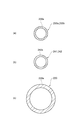
- FIG. 11 is a view showing a cross section of the support frame.
- FIG. 12 is a view showing a cross section of the weighing machine support frame and the ribs.
- FIG. 13 is a diagram illustrating a cross-sectional configuration of a beam member of a combination weighing device according to another embodiment.
- FIG. 14 is a diagram illustrating a cross-sectional configuration of a beam member of a combination weighing device according to another embodiment.
- FIG. 15 is a diagram illustrating a cross-sectional configuration of a beam member of a combination weighing device according to another embodiment.
- FIG. 16 is a diagram illustrating a cross-sectional configuration of a beam member of a combination weighing device according to another embodiment.
- FIG. 17 is a diagram illustrating a cross-sectional configuration of a beam member of a combination weighing device according to another embodiment.
- FIG. 1 is a perspective view of a combination weighing device according to an embodiment.
- FIG. 2 is a diagram schematically showing the configuration of the combination weighing device.
- FIG. 3 is a block diagram of the combination weighing device.
- FIG. 4 is a perspective view showing a state in which some components are removed from the combination weighing device shown in FIG. 1.
- FIG. 5 is a perspective view of the combination weighing device as viewed from below.
- FIG. 6 is a perspective view showing a lower part of the combination weighing device.
- FIG. 7 is a perspective view showing a configuration in the vicinity of the timing hopper.
- FIG. 8 is a front view showing the configuration of the lower part of the combination weighing device.
- the combination weighing device 1 includes an article supply chute 10, a dispersion table 20, a plurality of radiation feeders 30, a plurality of pool hoppers 40, a plurality of weighing hoppers 50, a collective discharge chute unit 60, a timing hopper 70, A weighing mechanism frame 80, a main body frame 90, a support frame 100, and a control unit 110 are provided.
- the combination weighing device 1 having the above configuration functions as follows. An article as an object to be weighed of the combination weighing device 1 is conveyed to the combination weighing device 1 by the cross feeder CF.
- the article is, for example, food.
- Articles conveyed by the cross feeder CF are put into the article supply chute 10.
- the articles thrown into the article supply chute 10 are supplied to the dispersion table 20.
- the dispersion table 20 conveys the article while dispersing the article, and supplies the article to a plurality of radiation feeders 30 arranged around the dispersion table 20.
- Each of the radiating feeders 30 conveys the articles supplied from the dispersion table 20 to the pool hoppers 40 provided corresponding to the respective radiating feeders 30, and supplies them to the pool hoppers 40.
- Each pool hopper 40 supplies articles to the weighing hopper 50 disposed below the pool hopper 40.
- the control unit 110 performs a combination weighing operation based on a weighing value (a weighing value of an article in the weighing hopper 50) of a load cell (weighing mechanism) 56 described later included in the weighing hopper 50. Then, the control unit 110 selects a combination of articles in which the result of the combination weighing calculation is within a predetermined allowable range and is closest to the target value.
- the weighing hopper 50 included in the selected combination supplies articles to the collective discharge chute unit 60.
- the collective discharge chute unit 60 supplies articles to the timing hopper 70.
- the timing hopper 70 supplies articles to, for example, a bag making and packaging machine installed at the subsequent stage of the combination weighing device 1.
- the article supply chute 10 is configured such that an article (see FIG. 2) of the cross feeder CF (see FIG. It is arranged below the end of the charging side. Further, the article supply chute 10 is disposed above the dispersion table 20. The article supply chute 10 receives supply of articles conveyed by the cross feeder CF and supplies articles to the distribution table 20.
- the dispersion table 20 is a table-like member formed in a conical shape.
- the distribution table 20 receives the supply of articles from the cross feeder CF installed above the distribution table 20 via the article supply chute 10.
- the dispersion table 20 is vibrated by an electromagnet (not shown) to convey the supplied article radially outward while being dispersed in the circumferential direction.
- the dispersion table 20 supplies the articles conveyed to the outer edge to a plurality of radiation feeders 30 arranged below the outer edge side of the dispersion table 20.
- the combination weighing device 1 has a plurality (14 in this case) of radiation feeders 30.
- the plurality of radiating feeders 30 are annularly arranged around the dispersion table 20.
- the plurality of radial feeders 30 extend radially about the dispersion table 20.
- Each radiating feeder 30 is, for example, vibrated by an electromagnet (not shown) so as to convey the article supplied from the dispersion table 20 outward in the radial direction (direction away from the dispersion table 20).
- Each radiating feeder 30 supplies the articles conveyed to the outer edge to a pool hopper 40 disposed below the outer rim side of each radiating feeder 30.
- the combination weighing device 1 has the same number of pool hoppers 40 as the radiation feeders 30. As shown in FIG. 4, one pool hopper 40 is disposed below the outer edge side of each radiation feeder 30. The pool hopper 40 temporarily stores articles supplied from the radiation feeder 30 disposed above.
- Each pool hopper 40 has a PH gate 42.
- the PH gate 42 is provided below the pool hopper 40.
- the pool hopper 40 supplies articles in the pool hopper 40 to the weighing hopper 50 disposed below the pool hopper 40 by opening the PH gate 42.
- Each PH gate 42 opens and closes when a link mechanism (not shown) is operated by the stepping motor 44.
- the operation of the stepping motor 44 is controlled by the control unit 110.
- the combination weighing device 1 has the same number of weighing hoppers 50 as the pool hopper 40.
- One weighing hopper 50 is disposed below each pool hopper 40.
- the weighing hopper 50 measures the weight of the article supplied from the pool hopper 40, that is, the weight of the article supplied from the radiation feeder 30 via the pool hopper 40.
- Each weighing hopper 50 has a WH gate 52.
- the WH gate 52 is provided below the weighing hopper 50.
- the weighing hopper 50 supplies the articles in the weighing hopper 50 to the collective discharge chute 60 when the WH gate 52 is opened.
- Each WH gate 52 opens and closes when a link mechanism (not shown) is operated by a stepping motor 54.
- the operation of the stepping motor 54 is controlled by the control unit 110.
- Each weighing hopper 50 has a load cell 56 for weighing an article held by the weighing hopper 50.
- the load cell 56 is an example of a weighing mechanism.
- the load cell 56 and a measurement signal indicating the measurement result are transmitted to a multiplexer 114 of the control unit 110 described later via an amplifier (not shown).
- the collective discharge chute part 60 is an example of a discharge path member.
- the collective discharge chute 60 includes an inner chute 62 and an outer chute 64 disposed around the inner chute 62.
- the inner chute 62 is a dust chute.
- the inner chute 62 has a mortar shape.
- the inner chute 62 is supplied with articles and the like (dust) that are out of the main discharge path.
- the weighed articles selected for the combination from the weighing hopper 50 are supplied to the outer chute 64.
- the outer chute 64 collects the articles supplied from the weighing hopper 50 and supplies them to the timing hopper 70.
- Timing Hopper The timing hopper 70 delivers the article supplied from the outer chute 64 to a subsequent bag making and packaging machine or the like.
- a gate 72 is provided below the timing hopper 70. By opening the gate 72, the articles in the timing hopper 70 are supplied to a subsequent bag making and packaging machine or the like.
- the gate 72 opens and closes when the link mechanism 74 is operated by the stepping motor 76. The opening and closing of the stepping motor 76 is controlled by the control unit 110. While the gate hopper 70 is closed, the timing hopper 70 receives the object to be weighed down from the outer chute 64, holds it inside, and opens the gate 72 to lower the held object to be measured. And hand it over to the subsequent bag making and packaging machine.
- the measuring mechanism frame 80 is a frame formed in a cylindrical shape.
- the weighing mechanism frame 80 mainly supports the dispersion table 20, the radiation feeder 30, the pool hopper 40, and the weighing hopper 50.
- the weighing mechanism frame 80 supports the dispersion table 20 and the radiation feeder 30 from below.
- the pool hopper 40 and the weighing hopper 50 are attached to the side surface of the weighing mechanism frame 80. 4 illustrates a state in which the radiation feeder 30, the pool hopper 40, and the weighing hopper 50 are removed from the combination weighing device 1 except for a part thereof.
- Various devices are accommodated inside the weighing mechanism frame 80. Specifically, an electromagnet (not shown) for vibrating the dispersion table 20, an electromagnet (not shown) for vibrating the radiation feeder 30, and a PH gate of the pool hopper 40 are provided inside the weighing mechanism frame 80.
- a stepping motor 44 for driving 42, a stepping motor 54 for driving the WH gate 52 of the weighing hopper 50, a load cell 56 of the weighing hopper 50, and the like are accommodated.
- the main body frame 90 is composed of four columns 92 extending in a substantially vertical direction, three beam members (laterally extending members) 94 disposed between the columns 92, and four columns And a weighing machine support frame 96.
- the column 92 and the beam member 94 are formed in an H shape in plan view by connecting the adjacent columns 92 with the beam member 94.
- the support column 92 is a hollow member having a square cross section and is configured by a flat surface.
- the upper end of the column 92 is closed by the upper surface 92a (one surface).
- the upper surface 92a is a plate-like member on a flat plate.
- the support column 92 has a vertical dimension, in other words, a substantially vertical dimension larger than a horizontal dimension.
- the upper surface 92a of the support column 92 is attached to the apparatus main body side (the inner side of the main body frame 90 (the side on which the measuring mechanism frame 80 and the collective discharge chute 60 are disposed)). In order to prevent falling, it is inclined with respect to the horizontal plane.
- the upper surface 92a being inclined means that the normal line of the upper surface 92a is inclined with respect to the vertical direction.
- the upper surface 92a of the support column 92 is inclined downward from the center of the apparatus main body toward the outside thereof. That is, the normal line of the upper surface 92a is inclined to the outside of the apparatus main body with respect to the vertical direction.
- the corner 92b inside the column 92 closest to the apparatus main body is disposed at the highest position, and the corner 92c farthest from the apparatus main body is the lowest. Placed in position.
- the plane A shown with the dashed-two dotted line in FIG. 9 has shown the virtual horizontal surface.
- each normal line of the upper surface 92a is inclined to the outside of the apparatus main body with respect to the vertical direction.
- the normal line of the upper surface 92a may be inclined inward of the apparatus main body with respect to the vertical direction.
- any structure may be used as long as dust adhering to the upper surface 92a, washing water at the time of cleaning, or the like falls to a specific place. Therefore, each normal line of the upper surface 92a is preferably inclined to either the outside or the inside of the apparatus main body with respect to the vertical direction.
- the beam member 94 is a member that extends laterally and is configured by a plane. In the present embodiment, the beam member 94 is a member that extends horizontally between the columns 92. A space S is formed below each beam member 94. By forming the space S below the beam member 94, it is easy to ensure the cleanability below the combination weighing device 1.
- the beam member 94 is a hollow member whose longitudinal section is formed in a square shape.
- the longitudinal section of the beam member 94 has a parallelogram shape.
- the longitudinal section of the beam member 94 has a parallelogram shape extending longer in the vertical direction than in the horizontal direction.
- An upper surface 94a in the longitudinal section of the beam member 94 is inclined downward from the apparatus main body side toward the outside. In other words, the upper surface 94a in the longitudinal section of the beam member 94 is downward from the side where the weighing mechanism frame 80 and the collective discharge chute portion 60 are arranged toward the side where the measurement mechanism frame 80 and the collective discharge chute portion 60 are not arranged. Inclined to.
- the lower surface 94b in the longitudinal section of the beam member 94 is also inclined downward from the inside of the main body frame 90 to the outside. In other words, the lower surface 94b in the longitudinal section of the beam member 94 is downward from the side where the weighing mechanism frame 80 and the collective discharge chute portion 60 are arranged toward the side where the measurement mechanism frame 80 and the collective discharge chute portion 60 are not arranged. Inclined to. Side surfaces (inner side surface 94c and outer side surface 94d) in the longitudinal section of the beam member 94 extend vertically (in the vertical direction).
- the upper surface 94a and the lower surface 94b are preferably inclined by, for example, 15 degrees or more with respect to the horizontal plane. As shown in FIG. 10, the value of the angle ⁇ is preferably 15 degrees or more. By making the angle ⁇ larger than 15 degrees, it is difficult for water droplets or the like to stay on the upper surface 94a, and it is easy to guide the water droplets to the outside of the combination weighing device 1 (outside the main body frame 90) along the upper surface 94a and the lower surface 94b. It is.
- the electric box 120 that accommodates the control device of the combination weighing device 1 including the control unit 110 is attached to the support column 92.
- the electric box 120 is fixed to the support column 92.
- the electric box 120 and one of the columns 92 are connected by a pipe 121 (see FIG. 4).
- the pipe 121 is a hollow member that communicates the internal space of the hollow support column 92 with the interior of the electric box 120. Inside the pipe 121, an electric wire for electrically connecting a device or the like housed in the measuring mechanism frame 80 and a device or the like in the electric box 120 is passed.
- the upper surface 120a of the electric box 120 is inclined downward from the apparatus main body side toward the outside away from the main body frame 90.
- the upper surface 120a is preferably inclined by 15 degrees or more with respect to the horizontal plane.
- the support device 92 is provided with a camera device 130.
- the camera device 130 images, for example, the dispersion state of articles on the dispersion table 20.
- the camera device 130 includes an attachment part 131 attached to the support column 92, an extendable part 132 extending in the vertical direction, and a camera part 133.
- the mounting part 131 is a hollow member having a circular cross section.
- the attachment part 131 is substantially L-shaped.
- the attachment portion 131 is fixed to the side surface 92 d of the support column 92.
- a part thereof extends outward from the side surface 92d, and a part thereof extends vertically through a bent portion that is bent by approximately 90 degrees.
- the stretchable part 132 is a hollow member having a circular cross section, and is stretchable. The distal end portion of the stretchable portion 132 is bent by approximately 90 degrees.
- the expansion / contraction part 132 is inserted in the attachment part 131 at the lower end part side, and can be extended / contracted with respect to the attachment part 131 by operating the first adjustment part 134 provided at the tip part of the attachment part 131. .
- the first adjustment unit 134 is rotated in one direction, thereby releasing the fixation of the expansion / contraction part 132 to the attachment part 131 and allowing the expansion / contraction part 132 to expand and contract.
- the 1st adjustment part 134 fixes the expansion-contraction part 132 with respect to the attachment part 131, and regulates expansion-contraction and rotation of the expansion-contraction part 132 by rotating in the other direction.
- the camera part 133 is inserted at one end part into the distal end part of the telescopic part 132.
- the camera unit 133 is rotatable with respect to the expansion / contraction part 132 by operating the second adjustment unit 135 provided at the tip of the expansion / contraction part 132.
- the second adjustment unit 135 is rotated in one direction, thereby releasing the fixation of the camera unit 133 with respect to the expansion / contraction unit 132 and enabling the camera unit 133 to rotate. Further, the second adjustment unit 135 rotates the camera unit 133 in the other direction, thereby fixing the camera unit 133 to the extendable unit 132 and restricting the rotation of the camera unit 133.
- the electric wire connected to the camera is passed through the extension part 132 and the attachment part 131.
- the weighing machine support frame 96 is a member that is disposed between the weighing mechanism frame 80 and the column 92 and connects the weighing mechanism frame 80 and the column 92. As shown in FIG. 11, the weighing machine support frame 96 is a hollow member configured by a plane. The weighing machine support frame 96 has a vertical dimension larger than a horizontal dimension. A weighing machine support frame 96 is provided on each column 92. Each weighing machine support frame 96 extends obliquely upward from each of the columns 92 toward the weighing mechanism frame 80. The weighing machine support frame 96 connects the lower part of the weighing mechanism frame 80 and the upper part of the column 92 of the main body frame 90 described later.
- the angle ⁇ formed by the lower surface 80b of the weighing mechanism frame 80 and the lower surface 96a of the weighing machine support frame 96 is an obtuse angle at the joint between the weighing mechanism frame 80 and the weighing machine support frame 96.
- the weighing machine support frame 96 is supported by the support column 92.
- the weighing machine support frame 96 supports the weighing mechanism frame 80. That is, the support column 92 supports the weighing mechanism frame 80 via the weighing machine support frame 96.
- the main body frame 90 is arranged on a gantry not shown.
- a device such as a bag making and packaging machine is disposed below the gantry, and articles are supplied from the timing hopper 70 to the device.
- the weighing machine support frame 96 is provided with a rib 98.
- the rib 98 extends on the lower surface 96a (lower part) of the weighing machine support frame 96 along the extending direction of the weighing machine support frame 96.
- the rib 98 is a plate-like member.
- the horizontal width dimension L ⁇ b> 1 of the rib 98 is smaller than the width dimension L ⁇ b> 2 of the weighing machine support frame 96.
- the inclination angle of the lower surface 98 a of the rib 98 with respect to the horizontal is larger than the inclination angle of the lower surface 96 a of the weighing machine support frame 96.
- the rib 98 becomes large as the dimension of an up-down direction becomes a lower end part side.
- One end of the rib 98 is joined to the support column 92.
- the rib 98 is provided with a through hole 98h.
- the through hole 98h is disposed at the joint portion with the weighing machine support frame 96 and on the column 92 side.
- the support frame 100 supports a group of components that are detachably provided in the combination weighing device 1.
- the support frame 100 includes a first support frame 200, a second support frame 220, and a third support frame 240.
- the first support frame 200 supports the article supply chute 10.
- the first support frame 200 includes a first frame 200a and a second frame 200b.
- Each of the first frame 200a and the second frame 200b has a perfect circular cross section as shown in FIG. That is, the entire surface 200s including the upper surface of each of the first frame 200a and the second frame 200b is curved.
- the first frame 200a is fixed to the weighing mechanism frame 80 and supports the second frame 200b.
- the first frame 200a and the second frame 200b are coupled by a connecting member 202.
- a screw is not used for the connecting member 202.
- the second frame 200 b supports the article supply chute 10 above the dispersion table 20.
- the second frame 200 b supports the article supply chute 10 via the attachment member 204.
- a screw is not used for the attachment member 204.
- the article supply chute 10 is detachably provided on the second frame 200b.
- the second support frame 220 supports the outer chute 64 of the collective discharge chute portion 60.
- the second support frame 220 has an annular shape.
- the cross section of the second support frame 220 has a perfect circle shape. That is, the second support frame 220 has a curved entire surface 220s including the upper surface.
- the second support frame 220 supports the outer chute 64 by the hook 222.
- the hook 222 is provided on the upper part of the outer peripheral surface of the outer chute 64.
- the hook 222 engages with the second support frame 220.
- the outer chute 64 is detachably provided on the second support frame 220 by the hook 222.
- the second support frame 220 may be formed integrally or may be formed by combining a plurality of members.
- the second support frame 220 is supported by the weighing machine support frame 96 of the main body frame 90. Specifically, as shown in FIG. 8, the weighing machine support frame 96 is formed with a through hole 96 h in the vicinity of the lower end joined to the support column 92. The second support frame 220 is inserted into the through hole 96 h and supported by the weighing machine support frame 96.
- the third support frame 240 supports the timing hopper 70.
- the third support frame 240 extends in a direction perpendicular to the first frame with the pair of first frames 241 extending in parallel with the timing hopper 70 positioned therebetween, and the timing hopper 70 positioned between the pair of first frames 241.
- a pair of second frames 242 for connecting the pair of first frames 241 to each other.
- Each of the first frame 241 and the second frame 242 has a perfect circular cross section as shown in FIG. That is, the entire surface 240s including the upper surface of each of the first frame 241 and the second frame 242 is curved.
- the first frame 241 is fixed to the beam member 94 by a fixed frame 243.
- the fixed frame 243 is a hollow member that has a flat surface and extends in the vertical direction.
- the end of the first frame 241 is connected to the lower end of the fixed frame 243.
- the fixed frame 243 is fixed to the inner side surface 94 c of the beam member 94 by the fixing member 244.
- the second frame 242 supports the timing hopper 70.
- One second frame 242 is provided with a stopper 245 as shown in FIG.
- the stopper 245 restricts the movement of the rod-like member 71 extending in parallel with the second frame 242 in the timing hopper 70.
- the stopper 245 has a movable part 245a.
- the movable portion 245a is located above the rod-shaped member 71 (abuts on the upper portion of the rod-shaped member 71) and restricts the movement of the rod-shaped member 71 in the vertical direction.
- the stopper 245 suppresses the timing hopper 70 from being lifted by the impact applied to the timing hopper 70 and the timing hopper 70 being detached from the second frame 242.
- the control unit 110 includes a CPU (Central Processing Unit) 112 and a memory 113 such as a ROM (Read Only Memory) and a RAM (Random Access Memory) (see FIG. 3).
- the control unit 110 includes a multiplexer 114, an A / D converter 115, and a DSP (digital signal processor) 116.
- the multiplexer 114 selects one measurement signal from the measurement signals of the load cell 56 in accordance with a command from the DSP 116 and transmits it to the A / D converter 115.
- the A / D converter 115 converts the measurement signal (analog signal) received from the multiplexer 114 into a digital signal according to the timing signal transmitted from the DSP 116 and transmits the digital signal to the DSP 116.
- the DSP 116 performs filter processing on the digital signal transmitted from the A / D converter 115.
- the control unit 110 is connected to each part of the combination weighing device 1 such as the dispersion table 20, the radiation feeder 30, the stepping motor 44, the stepping motor 54, the stepping motor 76, and the touch panel 117.
- the control unit 110 controls each unit of the combination weighing device 1 by causing the CPU 112 to execute a program stored in the memory 113.
- the upper surface and / or the lower surface of the main body frame 90 (the column 92 and the beam member 94) is inclined downward from the device side toward the outside. .
- cleaning water or the like adhering to the upper surface and / or the lower surface can easily fall to the outside of the apparatus. Therefore, it is possible to suppress the washing water or the like from falling inside or directly below the apparatus, and the hygiene is excellent.
- the support column 92, the beam member 94, and the weighing machine support frame 96 of the main body frame 90 are configured as a plane.
- the main body frame 90 can improve rigidity compared with the cylindrical frame of the same external dimension. Accordingly, it is possible to effectively suppress disturbances such as floor vibrations and vibrations caused by the device itself. As a result, the influence of disturbance or the like on the load cell 56 can be suppressed, and the measurement accuracy in the load cell 56 can be improved.
- the entire surface of the support frame 100 that supports a group of components that are detachably provided is curved. Therefore, safety can be ensured even when the operator grips the support frame 100 or contacts the support frame 100 when attaching or detaching components to / from the support frame 100.
- the cross section of the support frame 100 has a perfect circle shape. Thereby, while being able to improve safety
- the vertical dimension of the column 92, the beam member 94, and the weighing machine support frame 96 which are the main body frame 90, is larger than the horizontal dimension. If the vertical dimension is made larger than the horizontal dimension, the rigidity in the vertical direction of the column 92, the beam member 94, and the weighing machine support frame 96 can be further increased. As a result, vibration can be more effectively suppressed.
- a plate-like rib 98 extending below the weighing machine support frame 96 and having a smaller horizontal dimension than the weighing machine support frame 96 is provided.
- the inclination angle of the lower surface 98 a of the rib 98 is larger than the inclination angle of the lower surface 96 a of the weighing machine support frame 96.
- the rib 98 has a plate shape whose horizontal dimension is smaller than that of the weighing machine support frame 96, and the inclination angle of the lower surface 98a of the rib 98 is larger than the inclination angle of the lower surface 96a of the weighing machine support frame 96.
- the cleaning water or the like is easily concentrated on the lower surface 98a of the rib 98, and the cleaning water or the like is discharged along the lower surface 98a of the rib 98. Therefore, it is possible to suppress the accumulation of cleaning water or the like on the lower surface 98a of the rib 98, and as a result, the hygiene is further improved.
- the beam member 94 is disposed between the two support columns 92.
- a space S is formed below the beam member 94. Since the space S is formed below the beam member 94, cleaning is easy. Further, even when a part of the washing water or the like that has fallen to the outside of the combination weighing device 1 along the surface of the beam member 94 is accumulated below the combination weighing device 1, it is easy to find and remove this. is there.
- the third support frame 240 that supports the timing hopper 70 is fixed to the inner side surface 94 c of the beam member 94.
- a fixing location can be increased.
- the measurement accuracy can be improved.
- the link mechanism 74 provided in the timing hopper 70 employs a configuration in which screws are not exposed.
- an article or the like is likely to adhere to the screw thread and is difficult to clean. Therefore, by adopting a configuration in which the screw is not exposed in the link mechanism 74, hygiene can be improved.
- the camera device 130 is attached to the outer side surface 92d of the support column 92. Thereby, it is possible to suppress water drops or the like adhering to the camera device 130 from falling inside or directly below the present device, and the hygiene is excellent.
- the camera device is attached by a bracket whose position can be adjusted.
- the bracket is fixed to the column 92 by bolts. When using a bolt, there is a possibility that an article or the like may be sandwiched between the bolt and tightening the bolt. In this case, hygiene may be deteriorated.
- the present invention is not limited to the above embodiment.
- food has been described as an example of the article, but the article may be other.
- the dispersion table 20 may disperse articles by rotating.
- the radiation feeder 30 may convey articles
- the first support frame 200, the second support frame 220, and the third support frame 240 have been described with an example in which the cross section is a perfect circle, but the cross section may be an elliptical shape or the like. Good. In short, it is sufficient that at least the upper surface is curved. However, from the viewpoint of reducing the material cost, it is preferable that the cross section of each frame is a perfect circle.
- the configuration in which the collective discharge chute portion 60 includes the inner chute 62 and the outer chute 64 has been described as an example.
- the collective discharge chute portion 60 is limited to a configuration including the inner chute 62 and the outer chute 64.
- the collective discharge chute unit 60 may be configured with a single chute.
- the vertical cross section of the beam member 94 extends longer in the vertical direction than in the width direction, but is not limited to this, and may extend longer in the width direction. However, in order to keep the accuracy of the combination weighing device 1 high, it is preferable to secure the rigidity in the vertical direction of the beam member 94. In this case, the vertical cross section of the beam member 94 may extend long in the vertical direction. preferable.
- the configuration in which the support column 92 and the beam member 94 are hollow members has been described as an example, but the present invention is not limited to this, and a solid member may be used. However, from the viewpoint of reducing the weight of the combination weighing device 1 and reducing the material cost, it is preferable that the support column 92 and the beam member 94 are hollow members.
- the lower surface 94b in the longitudinal section of the beam member 94 is also inclined downward from the inner side to the outer side of the main body frame 90, but is not limited thereto.
- the lower surface 94b in the longitudinal section of the beam member 94 may not be inclined (or horizontal).
- the lower surface 94b in the longitudinal section of the beam member 94 may also be inclined downward from the inside of the main body frame 90 toward the outside. preferable.
- the mode in which the longitudinal section of the beam member 94 has a quadrangular shape (parallelogram shape) has been described as an example.
- the shape of the longitudinal section of the beam member 94 is not limited to this.
- the upper surface 94Aa and the lower surface 94Ab of the beam member 94A may be curved surfaces that incline downward from the inside to the outside of the main body frame 90.
- the beam member 94B has a groove shape in which the upper surface 94Ba and the lower surface 94Bb are inclined downward from the inner side to the outer side of the main body frame 90, and the outer side portions are opened. It may be.
- the beam member 94C may be a plate-like member in which the upper surface 94Ca and the lower surface 94Cb are inclined downward from the inside of the main body frame 90 toward the outside. From the viewpoint of the rigidity of the main body frame 90, it is preferable to have a portion extending in the vertical direction.
- the two beam members 94C are arranged in parallel with each other in the vertical direction, but the number of beam members 94C is not limited to this.
- the number of beam members 94C may be one, or three or more.
- the main upper surface of the longitudinal cross section of the beam member is the length when the upper surface of the beam member is projected on a straight line extending in the left-right direction (direction perpendicular to the vertical direction) in the cross-sectional view of the beam member, It means a surface that occupies 2/3 or more of the total projection length. The same applies to the main lower surface of the longitudinal section of the beam member.
- an upper surface 94Da that is a main upper surface and a lower surface 94Db that is a main lower surface are inclined downward from the inside to the outside of the main body frame 90.
- the beam member 94D may have an elliptical longitudinal section.
- the length of the upper surface 94Da projected onto a straight line extending in the left-right direction is represented as L1
- the length of the upper surface 94Dc projected onto a straight line extending in the left-right direction is represented as L2.
- the upper surface 94Da is the main upper surface.
- the cleaning water or the like attached to the beam member 94D easily falls to the outer side of the combination weighing device 11.
- the upper surface 94Ea that is the main upper surface and the lower surface 94Eb that is the main lower surface are inclined downward from the inside of the main body frame 90 toward the outside.
- the upper surface 94Ea and the lower surface 94Eb are inclined downward from the inner side to the outer side of the main body frame 90, the cleaning water or the like adhering to the beam member 94E easily falls to the outer side of the combination weighing device 1.
- the beam member 94 is disposed so as to extend horizontally between the columns 92, but is not limited thereto.
- the beam member 94 may be disposed so as to extend in an oblique direction between the columns 92 like a brace.
- the beam member 94 is disposed between the support columns 92, but is not limited thereto. Also for the beam members extending in the lateral direction used in portions other than between the columns 92, the longitudinal section thereof has an upper surface and / or a lower surface inclined downward from the inner side to the outer side of the main body frame 90. Similar effects can be obtained.
- the electric box 120 is fixed to the main body frame 90, but is not limited thereto.
- the electric box 120 is placed separately without being fixed to the main body frame 90, and the electric wire connecting the equipment and the like in the electric box 120 and the equipment and the like accommodated in the weighing mechanism frame 80 passes through the inside of the flexible tube or the like. You may be comprised so that it may lay to 120.
- the lower surface in the longitudinal section of the electric box 120 is not inclined
- the present invention is not limited to this.
- the lower surface in the longitudinal section of the electric box 120 is also inclined downward from the main body frame 90 side toward the side away from the main body frame 90.
- the lower surface in the longitudinal section of the electric box 120 is inclined by 15 degrees or more with respect to the horizontal plane.
- the support column 92 and the beam member 94 of the main body frame 90 are connected to each other by the beam member 94 and are formed in an H shape in plan view. It is not limited to this. For example, it is good also as a structure arrange
- a rubber member such as an emastler may be interposed at the joint portion between the metal members. Bacteria propagation may occur at the joint between the metal members. By interposing the rubber member between the metal members, the metal members do not come into contact with each other, so that propagation of various germs can be suppressed.
Landscapes
- Physics & Mathematics (AREA)
- General Physics & Mathematics (AREA)
- Weight Measurement For Supplying Or Discharging Of Specified Amounts Of Material (AREA)
- Basic Packing Technique (AREA)
- Supply Of Fluid Materials To The Packaging Location (AREA)
Abstract
Priority Applications (5)
| Application Number | Priority Date | Filing Date | Title |
|---|---|---|---|
| CN201580049741.1A CN106716084B (zh) | 2014-09-19 | 2015-09-18 | 组合计量装置 |
| DK15843049.6T DK3196611T3 (da) | 2014-09-19 | 2015-09-18 | Kombinationsvejeindretning |
| US15/511,763 US10323977B2 (en) | 2014-09-19 | 2015-09-18 | Support structure for a combination weighing device |
| JP2016548974A JP6599878B2 (ja) | 2014-09-19 | 2015-09-18 | 組合せ計量装置 |
| EP15843049.6A EP3196611B1 (fr) | 2014-09-19 | 2015-09-18 | Dispositif de pesage associatif |
Applications Claiming Priority (6)
| Application Number | Priority Date | Filing Date | Title |
|---|---|---|---|
| JP2014-191870 | 2014-09-19 | ||
| JP2014191870 | 2014-09-19 | ||
| JP2014223342 | 2014-10-31 | ||
| JP2014-223338 | 2014-10-31 | ||
| JP2014223338 | 2014-10-31 | ||
| JP2014-223342 | 2014-10-31 |
Publications (1)
| Publication Number | Publication Date |
|---|---|
| WO2016043325A1 true WO2016043325A1 (fr) | 2016-03-24 |
Family
ID=55533361
Family Applications (1)
| Application Number | Title | Priority Date | Filing Date |
|---|---|---|---|
| PCT/JP2015/076776 WO2016043325A1 (fr) | 2014-09-19 | 2015-09-18 | Dispositif de pesage associatif |
Country Status (6)
| Country | Link |
|---|---|
| US (1) | US10323977B2 (fr) |
| EP (1) | EP3196611B1 (fr) |
| JP (1) | JP6599878B2 (fr) |
| CN (1) | CN106716084B (fr) |
| DK (1) | DK3196611T3 (fr) |
| WO (1) | WO2016043325A1 (fr) |
Cited By (2)
| Publication number | Priority date | Publication date | Assignee | Title |
|---|---|---|---|---|
| JP2017198538A (ja) * | 2016-04-27 | 2017-11-02 | 大和製衡株式会社 | 組合せ秤 |
| WO2021157058A1 (fr) * | 2020-02-07 | 2021-08-12 | 大和製衡株式会社 | Balance de combinaison |
Families Citing this family (6)
| Publication number | Priority date | Publication date | Assignee | Title |
|---|---|---|---|---|
| AU2015381840B2 (en) * | 2015-02-04 | 2021-06-24 | Ishida Co., Ltd. | Combination weighing device |
| GB2538778B (en) * | 2015-05-28 | 2020-01-01 | Frito Lay Trading Co Gmbh | Multihead weigher and weighing method |
| EP3540386A4 (fr) * | 2017-07-13 | 2020-02-26 | Yamato Scale Co., Ltd. | Dispositif de pesage combiné |
| EP3867608A1 (fr) * | 2018-10-18 | 2021-08-25 | Marel A/S | Dispositif de montage pour fixer un alimentateur à vis sur une peseuse associative |
| JP2020153776A (ja) * | 2019-03-19 | 2020-09-24 | 株式会社イシダ | 組合せ計量装置 |
| GB202116937D0 (en) * | 2021-11-24 | 2022-01-05 | Ishida Europe Litimted | Adjustable dispersion system |
Citations (4)
| Publication number | Priority date | Publication date | Assignee | Title |
|---|---|---|---|---|
| JPH1019647A (ja) * | 1996-07-03 | 1998-01-23 | Ishida Co Ltd | 組合せ計量装置 |
| WO2001088491A1 (fr) * | 2000-05-19 | 2001-11-22 | Anritsu Corporation | Pesage combine |
| JP2012136332A (ja) * | 2010-12-27 | 2012-07-19 | Yamato Scale Co Ltd | 集合シュート支持構造および組合せ計量装置 |
| JP2014085165A (ja) * | 2012-10-22 | 2014-05-12 | Ishida Co Ltd | 組合せ計量装置 |
Family Cites Families (10)
| Publication number | Priority date | Publication date | Assignee | Title |
|---|---|---|---|---|
| AU541709B2 (en) * | 1981-08-18 | 1985-01-17 | K.K. Ishida Koki Seisakusho | Combinatorial weighing apparatus |
| JP2551422B2 (ja) * | 1987-01-26 | 1996-11-06 | 大和製衡 株式会社 | 計量包装装置 |
| ES2004391A6 (es) * | 1987-02-27 | 1989-01-01 | Daumar Talleres | Maquina pesadora automatica de productos alimenticios |
| JPH0638316A (ja) * | 1992-07-17 | 1994-02-10 | Mitsubishi Electric Corp | 配電盤の防水機構 |
| US6188029B1 (en) * | 1996-07-03 | 2001-02-13 | Ishida Co., Ltd. | Weighing apparatus having improved hopper detachability |
| WO2000066983A1 (fr) * | 1999-05-03 | 2000-11-09 | Bilwinco A/S | Machine de pesage |
| JP4181725B2 (ja) | 2000-03-09 | 2008-11-19 | アンリツ産機システム株式会社 | 組合せ計量装置 |
| JP2003128015A (ja) | 2001-10-22 | 2003-05-08 | Ishida Co Ltd | 整列装置及びそれを備えた整列計量システム |
| JP2008066445A (ja) * | 2006-09-06 | 2008-03-21 | Naigai Denki Kk | 電気電子機器収納用屋外形キャビネット |
| US8063321B2 (en) * | 2008-02-26 | 2011-11-22 | Precision, Inc. | Universal belt scale frame |
-
2015
- 2015-09-18 JP JP2016548974A patent/JP6599878B2/ja active Active
- 2015-09-18 DK DK15843049.6T patent/DK3196611T3/da active
- 2015-09-18 US US15/511,763 patent/US10323977B2/en active Active
- 2015-09-18 CN CN201580049741.1A patent/CN106716084B/zh active Active
- 2015-09-18 EP EP15843049.6A patent/EP3196611B1/fr active Active
- 2015-09-18 WO PCT/JP2015/076776 patent/WO2016043325A1/fr active Application Filing
Patent Citations (4)
| Publication number | Priority date | Publication date | Assignee | Title |
|---|---|---|---|---|
| JPH1019647A (ja) * | 1996-07-03 | 1998-01-23 | Ishida Co Ltd | 組合せ計量装置 |
| WO2001088491A1 (fr) * | 2000-05-19 | 2001-11-22 | Anritsu Corporation | Pesage combine |
| JP2012136332A (ja) * | 2010-12-27 | 2012-07-19 | Yamato Scale Co Ltd | 集合シュート支持構造および組合せ計量装置 |
| JP2014085165A (ja) * | 2012-10-22 | 2014-05-12 | Ishida Co Ltd | 組合せ計量装置 |
Non-Patent Citations (1)
| Title |
|---|
| See also references of EP3196611A4 * |
Cited By (3)
| Publication number | Priority date | Publication date | Assignee | Title |
|---|---|---|---|---|
| JP2017198538A (ja) * | 2016-04-27 | 2017-11-02 | 大和製衡株式会社 | 組合せ秤 |
| WO2021157058A1 (fr) * | 2020-02-07 | 2021-08-12 | 大和製衡株式会社 | Balance de combinaison |
| JP7391488B2 (ja) | 2020-02-07 | 2023-12-05 | 大和製衡株式会社 | 組合せ秤 |
Also Published As
| Publication number | Publication date |
|---|---|
| DK3196611T3 (da) | 2022-04-25 |
| EP3196611A4 (fr) | 2018-05-23 |
| JPWO2016043325A1 (ja) | 2017-06-29 |
| JP6599878B2 (ja) | 2019-10-30 |
| CN106716084B (zh) | 2020-11-20 |
| CN106716084A (zh) | 2017-05-24 |
| EP3196611A1 (fr) | 2017-07-26 |
| US20170299423A1 (en) | 2017-10-19 |
| US10323977B2 (en) | 2019-06-18 |
| EP3196611B1 (fr) | 2022-03-23 |
Similar Documents
| Publication | Publication Date | Title |
|---|---|---|
| JP6599878B2 (ja) | 組合せ計量装置 | |
| WO2016067883A1 (fr) | Dispositif de manipulation d'articles | |
| JP6255036B2 (ja) | 組合せ計量装置 | |
| US6703568B2 (en) | Combination weighing apparatus having a weighing device base, to which a plurality of weighing devices are fixed, that is directly fixed to a stand | |
| US9464931B2 (en) | Combination weigher | |
| WO2016129484A1 (fr) | Dispositif de pesage combiné | |
| US9995620B2 (en) | Combination scale with shielding tool | |
| US11125604B2 (en) | Combination weighing device including a movable and detachable discharge chute | |
| JP6305835B2 (ja) | 物品規制装置及びこれを備える組合せ秤 | |
| WO2016042969A1 (fr) | Dispositif de mesure de combinaison | |
| WO2021210167A1 (fr) | Structure de fixation de trémie et dispositif de pesée la comprenant | |
| JP5490607B2 (ja) | 組合せ秤 | |
| JP6804821B2 (ja) | 組合せ秤用ホッパ及びこれを備える組合せ秤 | |
| US20230091619A1 (en) | Seal structure and weighing machine comprising same | |
| JP7162886B2 (ja) | 組合せ計量装置 | |
| JP6305834B2 (ja) | 物品供給調整装置及びこれを備える組合せ秤 | |
| JP7266950B2 (ja) | 組合せ秤 | |
| JP2020148539A (ja) | 組合せ計量装置、及び組合せ計量装置用の架台 | |
| JP2010096651A (ja) | 組合せ秤 | |
| JP6000154B2 (ja) | 集合ホッパの取付構造及び組合せ秤 | |
| JP2020148668A (ja) | 組合せ秤 | |
| JP2003121249A (ja) | 組合せ計量装置 | |
| JP2012230065A (ja) | 計量装置 |
Legal Events
| Date | Code | Title | Description |
|---|---|---|---|
| 121 | Ep: the epo has been informed by wipo that ep was designated in this application |
Ref document number: 15843049 Country of ref document: EP Kind code of ref document: A1 |
|
| ENP | Entry into the national phase |
Ref document number: 2016548974 Country of ref document: JP Kind code of ref document: A |
|
| WWE | Wipo information: entry into national phase |
Ref document number: 15511763 Country of ref document: US |
|
| NENP | Non-entry into the national phase |
Ref country code: DE |
|
| REEP | Request for entry into the european phase |
Ref document number: 2015843049 Country of ref document: EP |
|
| WWE | Wipo information: entry into national phase |
Ref document number: 2015843049 Country of ref document: EP |