WO2016031353A1 - 自動分析装置用反応セル、その反応セルを搭載した自動分析装置、及びその自動分析装置を用いた分析方法 - Google Patents
自動分析装置用反応セル、その反応セルを搭載した自動分析装置、及びその自動分析装置を用いた分析方法 Download PDFInfo
- Publication number
- WO2016031353A1 WO2016031353A1 PCT/JP2015/067171 JP2015067171W WO2016031353A1 WO 2016031353 A1 WO2016031353 A1 WO 2016031353A1 JP 2015067171 W JP2015067171 W JP 2015067171W WO 2016031353 A1 WO2016031353 A1 WO 2016031353A1
- Authority
- WO
- WIPO (PCT)
- Prior art keywords
- reaction cell
- reaction
- sample
- reagent
- antifouling
- Prior art date
- Legal status (The legal status is an assumption and is not a legal conclusion. Google has not performed a legal analysis and makes no representation as to the accuracy of the status listed.)
- Ceased
Links
Images


Classifications
-
- B—PERFORMING OPERATIONS; TRANSPORTING
- B01—PHYSICAL OR CHEMICAL PROCESSES OR APPARATUS IN GENERAL
- B01L—CHEMICAL OR PHYSICAL LABORATORY APPARATUS FOR GENERAL USE
- B01L3/00—Containers or dishes for laboratory use, e.g. laboratory glassware; Droppers
- B01L3/02—Burettes; Pipettes
- B01L3/0289—Apparatus for withdrawing or distributing predetermined quantities of fluid
- B01L3/0293—Apparatus for withdrawing or distributing predetermined quantities of fluid for liquids
-
- G—PHYSICS
- G01—MEASURING; TESTING
- G01N—INVESTIGATING OR ANALYSING MATERIALS BY DETERMINING THEIR CHEMICAL OR PHYSICAL PROPERTIES
- G01N21/00—Investigating or analysing materials by the use of optical means, i.e. using sub-millimetre waves, infrared, visible or ultraviolet light
- G01N21/01—Arrangements or apparatus for facilitating the optical investigation
- G01N21/15—Preventing contamination of the components of the optical system or obstruction of the light path
-
- B—PERFORMING OPERATIONS; TRANSPORTING
- B01—PHYSICAL OR CHEMICAL PROCESSES OR APPARATUS IN GENERAL
- B01L—CHEMICAL OR PHYSICAL LABORATORY APPARATUS FOR GENERAL USE
- B01L3/00—Containers or dishes for laboratory use, e.g. laboratory glassware; Droppers
- B01L3/52—Containers specially adapted for storing or dispensing a reagent
-
- G—PHYSICS
- G01—MEASURING; TESTING
- G01N—INVESTIGATING OR ANALYSING MATERIALS BY DETERMINING THEIR CHEMICAL OR PHYSICAL PROPERTIES
- G01N21/00—Investigating or analysing materials by the use of optical means, i.e. using sub-millimetre waves, infrared, visible or ultraviolet light
- G01N21/17—Systems in which incident light is modified in accordance with the properties of the material investigated
- G01N21/55—Specular reflectivity
- G01N21/552—Attenuated total reflection
- G01N21/553—Attenuated total reflection and using surface plasmons
-
- G—PHYSICS
- G01—MEASURING; TESTING
- G01N—INVESTIGATING OR ANALYSING MATERIALS BY DETERMINING THEIR CHEMICAL OR PHYSICAL PROPERTIES
- G01N35/00—Automatic analysis not limited to methods or materials provided for in any single one of groups G01N1/00 - G01N33/00; Handling materials therefor
- G01N35/02—Automatic analysis not limited to methods or materials provided for in any single one of groups G01N1/00 - G01N33/00; Handling materials therefor using a plurality of sample containers moved by a conveyor system past one or more treatment or analysis stations
- G01N35/025—Automatic analysis not limited to methods or materials provided for in any single one of groups G01N1/00 - G01N33/00; Handling materials therefor using a plurality of sample containers moved by a conveyor system past one or more treatment or analysis stations having a carousel or turntable for reaction cells or cuvettes
-
- G—PHYSICS
- G01—MEASURING; TESTING
- G01N—INVESTIGATING OR ANALYSING MATERIALS BY DETERMINING THEIR CHEMICAL OR PHYSICAL PROPERTIES
- G01N35/00—Automatic analysis not limited to methods or materials provided for in any single one of groups G01N1/00 - G01N33/00; Handling materials therefor
- G01N35/10—Devices for transferring samples or any liquids to, in, or from, the analysis apparatus, e.g. suction devices, injection devices
- G01N35/1002—Reagent dispensers
-
- G—PHYSICS
- G01—MEASURING; TESTING
- G01N—INVESTIGATING OR ANALYSING MATERIALS BY DETERMINING THEIR CHEMICAL OR PHYSICAL PROPERTIES
- G01N35/00—Automatic analysis not limited to methods or materials provided for in any single one of groups G01N1/00 - G01N33/00; Handling materials therefor
- G01N35/10—Devices for transferring samples or any liquids to, in, or from, the analysis apparatus, e.g. suction devices, injection devices
- G01N35/1004—Cleaning sample transfer devices
-
- B—PERFORMING OPERATIONS; TRANSPORTING
- B01—PHYSICAL OR CHEMICAL PROCESSES OR APPARATUS IN GENERAL
- B01L—CHEMICAL OR PHYSICAL LABORATORY APPARATUS FOR GENERAL USE
- B01L2200/00—Solutions for specific problems relating to chemical or physical laboratory apparatus
- B01L2200/06—Fluid handling related problems
- B01L2200/0684—Venting, avoiding backpressure, avoid gas bubbles
-
- B—PERFORMING OPERATIONS; TRANSPORTING
- B01—PHYSICAL OR CHEMICAL PROCESSES OR APPARATUS IN GENERAL
- B01L—CHEMICAL OR PHYSICAL LABORATORY APPARATUS FOR GENERAL USE
- B01L2300/00—Additional constructional details
- B01L2300/08—Geometry, shape and general structure
- B01L2300/0809—Geometry, shape and general structure rectangular shaped
-
- B—PERFORMING OPERATIONS; TRANSPORTING
- B01—PHYSICAL OR CHEMICAL PROCESSES OR APPARATUS IN GENERAL
- B01L—CHEMICAL OR PHYSICAL LABORATORY APPARATUS FOR GENERAL USE
- B01L2300/00—Additional constructional details
- B01L2300/16—Surface properties and coatings
-
- B—PERFORMING OPERATIONS; TRANSPORTING
- B01—PHYSICAL OR CHEMICAL PROCESSES OR APPARATUS IN GENERAL
- B01L—CHEMICAL OR PHYSICAL LABORATORY APPARATUS FOR GENERAL USE
- B01L2300/00—Additional constructional details
- B01L2300/16—Surface properties and coatings
- B01L2300/161—Control and use of surface tension forces, e.g. hydrophobic, hydrophilic
- B01L2300/165—Specific details about hydrophobic, oleophobic surfaces
-
- B—PERFORMING OPERATIONS; TRANSPORTING
- B01—PHYSICAL OR CHEMICAL PROCESSES OR APPARATUS IN GENERAL
- B01L—CHEMICAL OR PHYSICAL LABORATORY APPARATUS FOR GENERAL USE
- B01L2300/00—Additional constructional details
- B01L2300/16—Surface properties and coatings
- B01L2300/168—Specific optical properties, e.g. reflective coatings
-
- G—PHYSICS
- G01—MEASURING; TESTING
- G01N—INVESTIGATING OR ANALYSING MATERIALS BY DETERMINING THEIR CHEMICAL OR PHYSICAL PROPERTIES
- G01N35/00—Automatic analysis not limited to methods or materials provided for in any single one of groups G01N1/00 - G01N33/00; Handling materials therefor
- G01N35/02—Automatic analysis not limited to methods or materials provided for in any single one of groups G01N1/00 - G01N33/00; Handling materials therefor using a plurality of sample containers moved by a conveyor system past one or more treatment or analysis stations
- G01N35/04—Details of the conveyor system
- G01N2035/0401—Sample carriers, cuvettes or reaction vessels
- G01N2035/0437—Cleaning cuvettes or reaction vessels
-
- G—PHYSICS
- G01—MEASURING; TESTING
- G01N—INVESTIGATING OR ANALYSING MATERIALS BY DETERMINING THEIR CHEMICAL OR PHYSICAL PROPERTIES
- G01N35/00—Automatic analysis not limited to methods or materials provided for in any single one of groups G01N1/00 - G01N33/00; Handling materials therefor
- G01N35/02—Automatic analysis not limited to methods or materials provided for in any single one of groups G01N1/00 - G01N33/00; Handling materials therefor using a plurality of sample containers moved by a conveyor system past one or more treatment or analysis stations
- G01N35/04—Details of the conveyor system
- G01N2035/0439—Rotary sample carriers, i.e. carousels
- G01N2035/0443—Rotary sample carriers, i.e. carousels for reagents
-
- G—PHYSICS
- G01—MEASURING; TESTING
- G01N—INVESTIGATING OR ANALYSING MATERIALS BY DETERMINING THEIR CHEMICAL OR PHYSICAL PROPERTIES
- G01N35/00—Automatic analysis not limited to methods or materials provided for in any single one of groups G01N1/00 - G01N33/00; Handling materials therefor
- G01N35/02—Automatic analysis not limited to methods or materials provided for in any single one of groups G01N1/00 - G01N33/00; Handling materials therefor using a plurality of sample containers moved by a conveyor system past one or more treatment or analysis stations
- G01N35/04—Details of the conveyor system
- G01N2035/0439—Rotary sample carriers, i.e. carousels
- G01N2035/0444—Rotary sample carriers, i.e. carousels for cuvettes or reaction vessels
-
- G—PHYSICS
- G01—MEASURING; TESTING
- G01N—INVESTIGATING OR ANALYSING MATERIALS BY DETERMINING THEIR CHEMICAL OR PHYSICAL PROPERTIES
- G01N35/00—Automatic analysis not limited to methods or materials provided for in any single one of groups G01N1/00 - G01N33/00; Handling materials therefor
- G01N35/02—Automatic analysis not limited to methods or materials provided for in any single one of groups G01N1/00 - G01N33/00; Handling materials therefor using a plurality of sample containers moved by a conveyor system past one or more treatment or analysis stations
- G01N35/04—Details of the conveyor system
- G01N2035/0439—Rotary sample carriers, i.e. carousels
- G01N2035/0453—Multiple carousels working in parallel
-
- G—PHYSICS
- G01—MEASURING; TESTING
- G01N—INVESTIGATING OR ANALYSING MATERIALS BY DETERMINING THEIR CHEMICAL OR PHYSICAL PROPERTIES
- G01N2201/00—Features of devices classified in G01N21/00
- G01N2201/12—Circuits of general importance; Signal processing
Definitions
- the present invention relates to a reaction cell for an automatic analyzer, an automatic analyzer equipped with the reaction cell, and an analysis method using the automatic analyzer.
- an automatic analyzer for example, a biochemical analyzer that performs biochemical analysis by measuring the absorbance of a reaction solution obtained by mixing a desired reagent with a sample such as serum and reacting it is known. It has been.
- a biochemical analyzer includes a container for storing a sample and a reagent, a reaction cell for injecting the sample and the reagent, a mechanism for automatically injecting the sample and the reagent into the reaction cell, and a sample and a reagent in the reaction cell.
- the system is equipped with an automatic stirring mechanism that mixes the sample, a mechanism that measures the spectral spectrum of the sample during or after the reaction, and an automatic washing mechanism that sucks and discharges the reaction solution after the spectral spectrum measurement is completed and cleans the reaction cell. It is said.
- glass or synthetic resin is generally used as described in JP-A-2005-30763 (Patent Document 2).
- Patent Document 3 Japanese Patent Application Laid-Open No. 2011-215193
- Patent Document 5 discloses a method for preventing contamination (nonspecific adsorption) of a biological substance on the surface of a synthetic resin.
- the water-soluble copolymer (P) is formed on the wall surface of the container / equipment or the like by the hydrophobic bond of the repeating unit (B). Is adsorbed, and the non-specific adsorption of proteins and the like is achieved by making the wall surface hydrophilic with the repeating unit (A) (when the water-soluble copolymer (P) contains the repeating unit (C), the repeating unit (C)). Can be prevented.
- the non-specific adsorption preventing coating agent is adsorbed to the base material (container / equipment) to be prevented from contamination by a hydrophobic bond.
- Patent Document 1 states that “the effect of bubbles becomes obvious in an experiment to reduce the reaction cell volume. The cause of this problem is the hydrophobic nature of the transparent resin used in the reaction cell material. With respect to this problem, Patent Document 1 states that “when the inner wall surface of the reaction cell was made hydrophilic, it was confirmed that bubble adhesion did not occur”.
- Automatic analyzers are increasingly required to reduce the amount of reagents and samples, and it is becoming increasingly important to reduce contamination of reaction cells and to suppress bubble adhesion.
- various reagents have been used based on user needs to analyze more various analysis items.
- substances that can contaminate the reaction cell are also diversifying.
- reaction cell material When glass (hydrophilic) or hydrophilic synthetic resin is used as the reaction cell material, it is effective for suppressing bubble adhesion, but the test solution climbs to the edge of the reaction cell by capillary action and is adjacent to the reaction cell. There is a problem that cross-contamination that mixes with other reagents tends to occur.
- Patent Document 5 describes a non-specific adsorption-preventing coating agent that adsorbs to the surface of a hydrophobic resin via a hydrophobic bond as a technique for preventing contamination by biological substances. Yes. However, there is no disclosure about a method for peeling off the non-specific adsorption preventing coating agent once adsorbed on the surface of the substrate.
- a sample is mixed with a desired reagent and reacted, but when a coating agent is present in the reaction cell, the coating agent in the reaction cell may be mixed with the sample depending on the analysis item (type of reagent). This may affect the reaction of the reagent and may reduce the analysis reliability.
- the coat layer is peeled off from the surface of the reaction cell and discharged from the reaction cell before analyzing the analysis item in question. At this time, it is necessary that the coat layer adsorbed on the reaction cell surface can be easily peeled off with an aqueous cleaning agent that can be used in an automatic analyzer.
- the problems to be solved by the present invention are as follows. That is, it is possible to suppress the bubble adhesion of the reaction cell and to prevent the reaction cell from being soiled by the coating agent only for a specific analysis item.
- the automatic analyzer has a sample disk mechanism for storing a plurality of sample cells for storing a sample to be inspected, a reaction disk for storing a plurality of reaction cells, and a reagent.
- a reagent disk mechanism for storing a reagent container, a sample supply dispensing mechanism having a sample nozzle for sucking a sample stored in a sample cell of the sample disk mechanism and supplying a predetermined amount to the reaction cell of the reaction disk, and a reagent Supplied by a reagent supply dispensing mechanism having a reagent dispensing nozzle that sucks the reagent contained in the reagent container of the disk mechanism and supplies a predetermined amount to the reaction cell of the reaction disk, and a sample supply dispensing mechanism Light that has passed through the reaction cell by irradiating the reaction cell with the mixture of the sample and the reagent supplied by the reagent supply dispensing mechanism.
- the detection unit detects the optical characteristics of the mixed liquid and the inner wall surface of the reaction cell supplied with the sample and the reagent on the reaction disk is contaminated with the sample or the reagent or the mixed liquid of the sample and the reagent.
- An antifouling liquid is supplied to the reaction cell, and after the antifouling film is formed on the inner wall surface of the reaction cell, the antifouling film is discharged from the reaction cell.
- a stripping solution for stripping the antifouling film from the inner wall surface of the reaction cell is supplied to the reaction cell where the film is formed, and the stripping solution for stripping the antifouling film from the inner wall surface of the reaction cell is supplied from the reaction cell.
- An antifouling film peeling mechanism for discharging, a computer for controlling the whole, and an operation panel for inputting information related to analysis to the computer are configured.
- the sample stored in the sample cell stored in the sample disk mechanism is sucked by the sample nozzle of the sample supply dispensing mechanism, and the sample sucked by this sample nozzle is removed.
- Reagent supplied to the reaction cell stored in the reaction disk, and the reagent stored in the reagent container of the reagent disk mechanism is sucked by the reagent dispensing nozzle of the reagent supply dispensing mechanism, and the reagent sucked by this reagent dispensing nozzle Is supplied to the reaction cell of the reaction disk, and the sample is prepared based on the signal obtained by detecting the light transmitted through the reaction cell by irradiating the reaction cell where the mixed solution of the supplied sample and reagent is formed.
- an antifouling solution is applied to the reaction cell before the sample sucked by the sample nozzle is supplied to the reaction cell stored in the reaction disk. After supplying and forming an antifouling film on the inner wall of the reaction cell, analyzing the sample, the mixed solution is discharged from the reaction cell, and the stripping solution is supplied to the reaction cell from which the mixed solution has been discharged to The antifouling film formed on the wall surface was peeled off.
- the present invention has a reaction cell for injecting a sample and a reagent for an automatic analyzer to form a mixed solution, and has a pair of wall surfaces that transmit light as side wall surfaces.
- a region in contact with the mixed liquid of the inner surfaces of the pair of light transmission walls is formed of a hydrophilic surface.
- the present invention it is possible to suppress the bubbles from adhering to the reaction cell and to prevent the reaction cell from being soiled by the coating agent only for specific analysis items.
- the burden of the maintenance which a user implements, such as periodic cleaning of the reaction cell can be reduced.
- by performing antifouling only on specific analysis items it is possible to prevent the analysis reliability from being lowered due to side effects of the coating agent in other items.
- it contributes to reducing the amount of reagent, and can contribute to reducing the running cost of the automatic analyzer.
- FIG. 1 is a perspective view showing a schematic configuration of an automatic analyzer according to Example 1 of the present invention. It is a front view which shows the schematic structure of the coating agent injection
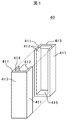
- the conventional reaction cell 40 includes a non-photometric surface outer wall portion 411, a non-photometric surface inner wall portion 412, a photometric surface outer wall portion 413, a photometric surface inner wall portion 414, and a bottom surface 415.
- the reaction cell 40 is surrounded by a wall having a thickness of 450, and has a closed portion 430 at the lower end and an opening 440 at the upper end.
- a known synthetic resin can be used as a material of the reaction cell 4 according to the automatic analyzer according to the present invention.
- it may be one kind selected from polycycloolefin, polycarbonate resin, acrylic resin, and polystyrene resin. It is desirable to select a polycycloolefin from the viewpoint of low water absorption, low moisture permeability, high total light transmittance, low refractive index, and low mold shrinkage.
- FIG. 3 shows a perspective external view of the reaction cell 4 according to the automatic analyzer according to the present invention.
- the portion 120 from the bottom surface 115 to the boundary line 119 in the photometric surface inner wall portion 114 is locally subjected to hydrophilic treatment.
- a local hydrophilization treatment method a known method can be applied.
- the hydrophilic region 120 is further coated with an antifouling film, so that contamination of the inner wall surfaces 114 and 112 of the reaction cell 4 can be prevented.
- an antifouling film a known water-soluble resin can be used. Examples thereof include polyethylene glycol and polyvinyl pyrrolidone.
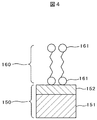
- FIG. 4 shows a cross-sectional view of the hydrophilized region 120 where the antifouling film is formed.
- the base material 150 of the reaction cell 4 includes a polycycloolefin 151 and a hydrophilic layer 152.
- the antifouling film 160 has a hydrophilic portion 161.
- the antifouling film 160 is adsorbed on the surface of the hydrophilic layer 152 through hydrogen bonds. Since the hydrogen bond is weakened by ions or alkali, the adsorbed antifouling film 160 can be easily separated from the hydrophilic layer 152 by washing with an aqueous detergent such as an alkali detergent.
- An antifouling film-forming polycycloolefin flat plate was immersed in an alkaline cleaner for 1 minute and then rinsed with water.
- the polycycloolefin flat plate was cleaned as described above.
- As the coating agent polyethylene glycol having an amino terminal group with an average molecular weight of 5,000 (hereinafter referred to as PEG) was used.
- PEG polyethylene glycol having an amino terminal group with an average molecular weight of 5,000
- Table 1 shows the results of water contact angle measurement.
- the contact angle decreased from 69 degrees to 55 degrees, which was a value almost equal to the contact angle before the coating treatment (before the cleaning treatment). This is presumably because the PEG coated on the hydrophilic polycycloolefin surface was peeled off by the alkali cleaning treatment.
- the method of coating the antifouling film on the polycycloolefin, which is a hydrophobic material is shown.
- the glass having a hydrophilic surface may be coated.
- the above (1) hydrophilization treatment may be omitted.
- XPS X-ray photoelectron spectroscopy
- a surface plasmon resonance (SPR) measuring device was used to evaluate the antifouling effect of a sample (sensor chip) whose surface was antifouling treated.
- the SPR measurement device is a device that optically measures a change in refractive index near the sensor chip surface in a liquid.
- an organic substance such as protein is adsorbed on the sensor chip surface
- the refractive index near the surface changes according to the mass of the adsorbed substance.
- the correlation between the refractive index change and the mass change is known, and the mass of the adsorbate can be known from the refractive index change amount.
- the antifouling effect was evaluated by the following procedure. (21) Film formation of synthetic resin on the surface of the sensor chip The surface of the sensor chip whose outermost surface was gold was cleaned by irradiation with the excimer light for 1 minute. A polycycloolefin solution dissolved in an organic solvent was applied to the cleaned sensor chip surface by spin coating. Thus, a sensor chip 304 having a polycycloolefin layer 303 formed on the outermost surface was obtained.
- FIG. 5 shows a schematic diagram of a cross section of the sensor chip 304 obtained by the procedure described above.
- the sensor chip 304 includes a glass substrate 301, a gold film 302, and a polycycloolefin layer 303.
- the refractive index is utilized using an evanescent wave that oozes out to the surface of the gold film 302 on the opposite side as viewed from the surface 311 side. Measure changes.
- the evanescent wave seepage range is several hundred nm from the surface of the gold film 302, and the film thickness of the polycycloolefin layer 303 needs to be thinner than the seepage range.
- the film thickness of the polycycloolefin layer 303 obtained by the method described above was approximately 30 nm as measured by a step gauge.
- the sensor chip 304 obtained above was mounted on an SPR measurement device.
- the liquid feeding flow rate to the sensor chip 304 of the SPR device was always 20 ⁇ l per minute.
- SPR signal the detection signal of the SPR measurement device
- a total of 100 ⁇ l of alkaline detergent was fed for 5 minutes to clean the surface of the polycycloolefin layer 303 of the sensor chip 304, and then water was fed again.
- Model contamination As model contamination, a phosphate buffer in which bovine serum albumin (hereinafter referred to as BSA) simulating protein contamination was dissolved at a concentration of 40 mg / ml was used. In order to simulate latex reagent contamination, a 2.5 w / v% suspension (hereinafter referred to as amino latex) of polystyrene latex having a particle size of 0.1 ⁇ m whose surface was modified with amino groups was used. The sensor chip used for evaluation was replaced every time the type of coating agent and model contamination was changed.
- BSA bovine serum albumin
- Table 4 shows the evaluation results of the antifouling effect by PEG, the antifouling effect by PVP, and the antifouling effect of Comparative Example 1.
- the effect of antifouling with PEG and antifouling with PVP was both less than 0.01 ng / mm 2 (below the detection limit of the SPR measuring device).
- the adsorption amount was 0.13 ng / mm 2 .
- the polycycloolefin has been described as an example.
- the antifouling according to the present invention is applicable to synthetic resins such as polyethylene, polypropylene, polystyrene, polyvinyl chloride, and polycarbonate. it can.
- the inner wall surface of the photometric surface of the reaction cell is a hydrophilic surface in the area irradiated with light from the light source of the automatic analyzer, and this hydrophilic surface is coated with a water-soluble resin. It is characterized by that. Since the water-soluble resin is adsorbed on the hydrophilic surface through hydrogen bonds, the water-soluble resin can be easily peeled off with an aqueous cleaner such as an alkaline cleaner.
- FIG. 6A A configuration example of the automatic analyzer 100 according to the first embodiment is shown in FIG. 6A.
- the automatic analyzer 100 shown in FIG. 6A schematically includes a sample disk mechanism 1, a sample supply dispensing mechanism 2 having a sample nozzle 27, a reaction disk 3, a reagent disk mechanism 5, and a reagent pipe having a reagent nozzle 28.
- a petting mechanism 7 and a computer 19 that controls the whole through an interface 23 are provided.
- sample disk mechanism 1 A large number of sample cells 25 are arranged in the sample disk mechanism 1.
- a sample disk mechanism which is a sample storage mechanism mounted on a disk-shaped mechanism
- a sample rack generally used in an analyzer
- sample rack it may be in the form of a sample holder.
- the sample here refers to a liquid to be inspected used for reaction in the reaction cell 4 in the reaction disk 3, and may be a collected sample stock solution such as serum or urine, and it may be diluted or pretreated. It may be a solution that has been processed as described above.
- the sample accommodated in the sample cell 25 is extracted by the sample nozzle 27 of the sample supply dispensing mechanism 2 and injected into a predetermined reaction cell 4 in the reaction disk 3.
- the reagent disk mechanism 5 includes a large number of reagent containers 6.
- a reagent supply dispensing mechanism 7 is arranged in the reagent disk mechanism 5, and the reagent is sucked by the reagent nozzle 28 of the reagent supply dispensing mechanism 7 and a predetermined reaction cell in the reaction disk 3. 4 is injected.
- the automatic analyzer 100 shown in FIG. 6 includes two reagent disk mechanisms 5 and a mechanism associated therewith.
- the automatic analyzer 100 is equipped with a spectrophotometer 10 and a light source 26. Between the spectrophotometer 10 and the light source 26, a reaction disk 3 that accommodates a measurement object is disposed. On the outer periphery of the reaction disk 3, for example, 120 reaction cells 4 having an inner wall made hydrophilic are installed. Further, the entire reaction disk 3 is held at a predetermined temperature by a thermostatic chamber 9. The specimen and reagent supplied to the reaction cell 4 are stirred by the stirring mechanism 8.
- the automatic analyzer 100 is equipped with an antifouling film forming mechanism 30 and an antifouling film peeling mechanism 34.
- the antifouling film forming mechanism 30 includes a coating agent injection nozzle 31 and a coating agent suction nozzle 32
- the antifouling film peeling mechanism 34 includes a peeling liquid injection nozzle 35 and a peeling liquid suction nozzle 36. .
- reaction cell cleaning mechanism 11 is a reaction cell cleaning mechanism, which supplies the cleaning agent supplied from the cleaning agent supply unit 13 to the reaction cell 4 arranged on the outer periphery of the reaction disk 3 to clean the inside of the reaction cell 4.
- the cleaning agent in the reaction cell 4 after cleaning is sucked by the suction nozzle 12 and discharged from the reaction cell 4.
- the interface 23 includes a computer 19, a Log converter and A / D converter 18, a reagent pipetter 17, a washing water pump 16, a sample pipetter 15, a printer 20, a CRT 21, and a floppy (registered trademark) disk as a storage device 22.
- a hard disk, an operation panel 24, and a computer 19 are connected. Each part of the analyzer 100 is controlled by the computer 19 via the interface 23.
- the operator inputs analysis request information using the operation panel 24.
- the analysis request information input by the operator is stored in the computer 19.
- analysis items to be coated are stored.
- the microcomputer 38 has the antifouling film forming mechanism 30.
- the antifouling film peeling mechanism 34 is processed. This makes it possible to prevent the reaction cell from being contaminated with the coating agent only with the specific analysis item.
- the configuration of the coating agent injection nozzle 31 of the antifouling film forming mechanism 30 is shown in FIG. 6B.
- the coating agent injection nozzle 31 includes a nozzle portion 311, a nozzle vertical drive portion 312, a nozzle support arm 313, and a coating agent supply pipe 314.
- the computer 19 controls the antifouling film forming mechanism 30 so that when the predetermined reaction cell 4 reaches the position of the coating agent injection nozzle 31, the nozzle unit 311 supported by the nozzle support arm 313 is moved to the nozzle up / down drive unit. Lower at 312. In this state, the coating agent supplied from the coating agent supply / recovery unit 33 through the coating agent supply pipe 314 is injected into the reaction cell 4 from the nozzle unit 311. Note that a plurality of types of coating agents may be stored inside the coating agent supply / recovery unit 33, and the types of coating agents supplied to the reaction cell 4 may be changed according to analysis items.
- the supply of the coating agent from the coating agent supply / recovery unit 33 is stopped, and the nozzle unit 311 is raised by being driven by the nozzle vertical drive unit 312.
- the coating agent in the reaction cell 4 is sucked by the coating agent suction nozzle 32.
- the vertical movement of the nozzle unit 311 may be synchronized with other mechanisms such as the reaction vessel cleaning mechanism 11, and in that case, the vertical driving unit can be shared by a plurality of mechanisms.
- the computer 19 controls the antifouling film peeling mechanism 34 to inject the peeling liquid supplied from the peeling liquid supply / recovery unit 37 into the reaction cell 4 with the peeling liquid injection nozzle 35, and after the antifouling film is peeled off
- the stripping solution in the reaction cell 4 is sucked by the stripping solution suction nozzle 36.
- the stripping solution supply / recovery unit 37 stores a plurality of types of stripping solutions, and changes the type of stripping solution supplied to the reaction cell 4 according to the type of antifouling film formed inside the reaction cell 4. May be.
- the configuration of the coating agent suction nozzle 32, the stripping solution injection nozzle 35, and the stripping solution suction nozzle 36 is basically the same as the configuration of the coating agent injection nozzle 31 shown in FIG. Omitting the magazine.
- the measurement target specimen placed in the sample cell 25 and set at a predetermined position in the specimen storage unit mechanism 1 is in accordance with the analysis request information stored in the computer 19 and the sample pipettor 15 and the specimen supply part.
- a predetermined amount is dispensed into the reaction cell 4 by the sample nozzle 27 of the injection mechanism 2.
- the sample nozzle 27 that dispenses a predetermined amount of sample into the reaction cell 4 is washed and used for dispensing the next sample.
- the operator inputs analysis request information using the operation panel 24.
- the analysis request information input by the operator is stored in the memory in the computer 19 and the storage unit 38 that stores the specimen number of the sample to be physically cleaned.
- FIG. 7 shows an operation flow of the automatic analyzer 100 having the above configuration.
- the operation panel 24 receives input of analysis request information from the operator, the analysis request information is stored in the memory in the computer 19, and the operation of the automatic analyzer 100 starts.
- step S701 the reaction cell cleaning mechanism 11 receives the supply of the cleaning agent and water from the cleaning agent supply unit 13 and the cleaning water pump 16, and cleans the inside of the reaction cell 4.
- the cleaning agent and water in the reaction cell 4 are sucked by the suction nozzle 12.
- step S702 blank water is injected into the reaction cell 4 by a blank water injection mechanism (not shown).
- a blank water injection mechanism not shown.
- step S703 the blank water injected into the reaction cell 4 is sucked by a blank water suction nozzle (not shown).
- step S704 based on the information in the memory in the storage unit 38 and the analysis request information, the computer 19 determines whether or not it is a target for antifouling film coating that causes the reaction cell 4 to process the antifouling film forming mechanism 30.
- step S705 the antifouling film forming mechanism 30 is controlled and the coating agent stored in the coating agent supply / collection unit 33 is stored. Is supplied into the reaction cell 4 from the nozzle portion 311 of the coating agent injection nozzle 31. After the antifouling film is formed in the reaction cell 4 by the supplied coating agent 33, the coating agent supplied into the reaction cell 4 is sucked by the coating agent suction nozzle 32 in step S706. In the case of an analysis item that is not a coating target (No in step S704), steps S705 and S706 are skipped, and the operation of step S707 is performed.
- step S707 the sample to be measured stored in the sample cell 25 set at a predetermined position of the sample disk mechanism 1 is supplied to the sample pipettor 15 and the sample supply distribution according to the analysis request information stored in the memory of the computer 19. A predetermined amount is dispensed into the reaction cell 4 set on the reaction disk 3 by the sample nozzle 27 of the injection mechanism 2.
- step S708 a predetermined amount of reagent taken out from a predetermined reagent container 6 out of the reagent containers 6 stored in the reagent disk mechanism 5 by the reagent nozzle 28 of the reagent pipetting mechanism 7 into the reaction cell 4 into which the sample has been dispensed. Is dispensed.
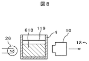
- step S709 the sample / reagent mixture 610 supplied to the reaction cell 4 is stirred by the stirring rod 29 of the stirring mechanism 8 or an ultrasonic element (not shown).
- step S710 the mixed solution (reaction solution) 610 of the sample and the reagent in the reaction cell 4 is sucked with a reaction solution suction nozzle (not shown).
- a reaction solution suction nozzle not shown.
- the reaction disk 3 is rotated at a predetermined angle at a predetermined tact time until suction of the reaction liquid 610 is started in step S710. Continue index rotation with.
- the absorbance does not change and is constant from the start of measurement (S701) until the sample is dispensed into the reaction cell 4 (S707). Thereafter, when the reagent is dispensed into the reaction cell (S708), the sample and reagent mixed solution 610 is formed and the absorbance changes, and when the mixed solution 610 is further stirred (S709), the absorbance further increases, and then reaches a certain value. After the measurement is completed, the measurement is finished, and the reaction solution which is the mixed solution 610 in the reaction cell is sucked (S710), and the measurement is finished.
- the change in absorbance due to the formation of the antifouling film (S705, S706) is sufficiently smaller than the change in absorbance due to the sample-reagent mixed solution 610.
- the absorbance does not change from the initial state, or even if it changes, no significant change is observed. In this case, it is determined that the sample does not react with the reagent and the sample does not contain a substance to be detected with the reagent.
- step S711 whether the computer 19 causes the antifouling film peeling mechanism 30 to perform processing to peel the antifouling film coated on the inner wall surface of the reaction cell 4 based on the information in the memory in the storage unit 38 and the analysis request information. Decide whether or not.
- step S711 the antifouling film peeling mechanism 34 is controlled in step S712 to remove the peeling liquid.
- the stripping solution supplied from the supply / recovery unit 37 is injected into the reaction cell 4 from the stripping solution injection nozzle 35.
- step S713 the stripping solution in the reaction cell 4 is sucked by the stripping solution suction nozzle 36.
- step S712 and step S713 are skipped, and the operation of step S714 is performed.
- the formation of the antifouling film may not necessarily be performed immediately before the analysis, for example, when the use of the apparatus is terminated for a certain period of time, An antifouling film may be formed while the apparatus transitions from the use state to the stop state. Thereby, the time for forming the antifouling film can be omitted when the use of the apparatus is resumed.
- the antifouling film is not necessarily removed immediately after the analysis. For example, the antifouling film is peeled off after the reaction cell 4 is used for the analysis a plurality of times while the antifouling film is formed in the reaction cell 4. May be.
- step S714 as in step S701, the reaction cell cleaning mechanism 11 receives the supply of cleaning agent and water from the cleaning agent supply unit 13 and the cleaning water pump 16, and cleans the inside of the reaction cell 4. After the cleaning is completed, the cleaning agent and water in the reaction cell 4 are sucked by the suction nozzle 12. The reaction cell 4 for which step S714 has been completed is sequentially used for the next analysis.
- the absorbance signal of the mixed solution 610 in the reaction cell 4 measured by the spectrophotometer 10 is taken into the computer 19 via the Log converter and A / D converter 18 and the interface 23.
- the data relating to the absorbed absorbance is converted into a concentration value, and the concentration value is stored in a floppy disk or a hard disk of the storage device 22 or output to the printer 20.
- inspection data can be displayed on the CRT 21.
- step S705 an example in which the coating agent is injected into the reaction cell 4 in step S705 and then the coating agent is sucked in step S706 has been described.
- step S705 there is some time between step S705 and step S706. You may do it. That is, after injecting the coating agent into the reaction cell 4 in step S705, the use of the reaction cell 4 is skipped (cell skip) instead of immediately executing S706 to suck the coating agent and starting S706.
- the time until the coating agent is adsorbed on the inner wall surface of the reaction cell may be secured after a certain time.
- the reaction disk 3 may be index rotated between step S705 and step S706, so that only the reaction cell 4 can be skipped and other reaction cells 4 can be used for analysis. .
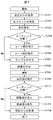
- FIG. 9 shows an operation flow of the automatic analyzer 100 when cell skip is used. 9, steps that execute the same contents as those described in FIG. 7 are denoted by the same step numbers as in FIG. In this operation, there is a cell skip S901 in step S901 between step S705 and step S706.
- step S901 the reaction cell 4 into which the coating agent has been injected is skipped, and the coating agent is placed inside the reaction cell 4 for an arbitrary time. Is retained. Thereby, the time for the coating agent to be adsorbed on the inner wall surfaces 112, 114, 115 of the reaction cell 4 can be secured, and an antifouling film can be reliably formed on the reaction cell 4.
- the cell skip may be performed between step S712 and step S713.
- the stripping solution is held in the reaction cell 4 for an arbitrary time, the time for stripping the antifouling film can be secured, and the antifouling film can be reliably peeled off.
- the cell skip may be performed twice between step S901 and step S712 and step S713.
- the antifouling film can be formed on the reaction cell 4 and the formed antifouling film can be reliably peeled off from the reaction cell 4.
- Example 2 shows an example in which the antifouling film forming mechanism and the antifouling film peeling mechanism constitute the automatic analyzer 200 as independent mechanisms.
- the other mechanism can also function as the antifouling film forming mechanism or the antifouling film peeling mechanism. Thereby, space saving of the automatic analyzer 200 is attained.
- FIG. 10 shows the configuration of the automatic analyzer 200 according to the present embodiment.
- the same reference numerals are given to the same components as those described in FIG. 6 in the first embodiment, and the description thereof is omitted.
- the coating agent is supplied in a part of the reagent containers 331 of the reagent containers 6 of the reagent disk mechanism 5.
- the coating agent placed in the reagent container 331 can be supplied into the reaction cell 4 by the reagent supply dispensing mechanism 7.
- the coating agent can be mixed with the reagent of the specific analysis item in advance, and the coating agent can be dispensed into the reaction cell 4 together with the reagent of the specific analysis item.
- the stripping solution supply / recovery unit 371 is connected to the reaction vessel cleaning mechanism 11 instead of the stripping solution supply / recovery unit 37 in the first embodiment.
- the stripping solution can be injected into the reaction cell 4 by the reaction vessel cleaning mechanism 11.
- the stripping solution may be mixed with the cleaning agent in advance, and the stripping solution may be supplied into the reaction cell 4 together with the cleaning agent.
- the cleaning agent may be used as a stripping solution, and the cleaning agent supply unit 13 may supply the cleaning agent as a stripping solution into the reaction cell 4.
- the coating agent may be supplied alone to the reaction cell 4 from the reaction vessel cleaning mechanism 11, or the coating agent previously contained (mixed) in the cleaning agent may be supplied to the reaction cell 4. Good.
- blank water may contain a coating agent in advance and supplied to the reaction cell 4 from a blank water supply nozzle (not shown).
- this invention is not limited to the above-mentioned Example, Various modifications are included.
- the above-described embodiments have been described in detail for easy understanding of the present invention, and are not necessarily limited to those having all the configurations described.
- a part of the configuration of one embodiment can be replaced with the configuration of another embodiment, and the configuration of another embodiment can be added to the configuration of one embodiment.
- each of the above-described configurations, functions, processing units, processing means, and the like may be realized by hardware by designing a part or all of them with, for example, an integrated circuit.
- Each of the above-described configurations, functions, and the like may be realized by software by interpreting and executing a program that realizes each function by the processor.
- Information such as programs, tables, and files for realizing each function can be stored in a recording device such as a memory, a hard disk, an SSD (Solid State Drive), or a recording medium such as an IC card, an SD card, or a DVD.
- control lines and information lines indicate what is considered necessary for the explanation, and not all the control lines and information lines on the product are necessarily shown. Actually, it may be considered that almost all the components are connected to each other.
- Stirring rod 30 ... Antifouling film formation mechanism 31 ... Coating agent supply nozzle 32 ... Coating agent suction nozzle 33 ... Coating agent 34 ... Antifouling film peeling mechanism 35 ... Stripping solution supply nozzle 36 ... Stripping solution suction Nozzle 37 ... Stripping solution 38 ... Storage unit 111 ... Non-photometric surface outer wall 112 ... Non-photometric surface inner wall 113 ... Photometric surface outer wall 114 ... Photometric surface inner wall 115 ... ⁇ Bottom surface 120 ... Hydrophilic region 130 ... Closed portion 140 ... Opening portion 150 ... Cell substrate 151 ... Polycycloolefin 152 ... Hydrophilic layer 160 ... Anti-fouling membrane 161 ... hydrophilic part 301 ... glass substrate 302 ... gold film 303 ... polycycloolefin.
Landscapes
- Chemical & Material Sciences (AREA)
- Health & Medical Sciences (AREA)
- Analytical Chemistry (AREA)
- Immunology (AREA)
- Pathology (AREA)
- Physics & Mathematics (AREA)
- Life Sciences & Earth Sciences (AREA)
- Biochemistry (AREA)
- General Health & Medical Sciences (AREA)
- General Physics & Mathematics (AREA)
- Chemical Kinetics & Catalysis (AREA)
- Clinical Laboratory Science (AREA)
- Medicinal Chemistry (AREA)
- Optical Measuring Cells (AREA)
- Automatic Analysis And Handling Materials Therefor (AREA)
- Sampling And Sample Adjustment (AREA)
Priority Applications (3)
| Application Number | Priority Date | Filing Date | Title |
|---|---|---|---|
| EP15836483.6A EP3187855A4 (en) | 2014-08-29 | 2015-06-15 | Reaction cell for automatic analysis device, automatic analysis device equipped with said reaction cell, and analysis method using said automatic analysis device |
| CN201580030661.1A CN106461536A (zh) | 2014-08-29 | 2015-06-15 | 自动分析装置用反应池、搭载该反应池的自动分析装置、及使用该自动分析装置的分析方法 |
| US15/325,929 US20170199115A1 (en) | 2014-08-29 | 2015-06-15 | Reaction cell for automatic analysis device, automatic analysis device equipped with said reaction cell, and analysis method using said automatic analysis device |
Applications Claiming Priority (2)
| Application Number | Priority Date | Filing Date | Title |
|---|---|---|---|
| JP2014175019A JP6216298B2 (ja) | 2014-08-29 | 2014-08-29 | 自動分析装置及びそれを用いた分析方法 |
| JP2014-175019 | 2014-08-29 |
Publications (1)
| Publication Number | Publication Date |
|---|---|
| WO2016031353A1 true WO2016031353A1 (ja) | 2016-03-03 |
Family
ID=55399258
Family Applications (1)
| Application Number | Title | Priority Date | Filing Date |
|---|---|---|---|
| PCT/JP2015/067171 Ceased WO2016031353A1 (ja) | 2014-08-29 | 2015-06-15 | 自動分析装置用反応セル、その反応セルを搭載した自動分析装置、及びその自動分析装置を用いた分析方法 |
Country Status (5)
| Country | Link |
|---|---|
| US (1) | US20170199115A1 (https=) |
| EP (1) | EP3187855A4 (https=) |
| JP (1) | JP6216298B2 (https=) |
| CN (1) | CN106461536A (https=) |
| WO (1) | WO2016031353A1 (https=) |
Families Citing this family (2)
| Publication number | Priority date | Publication date | Assignee | Title |
|---|---|---|---|---|
| KR20210146915A (ko) | 2019-03-29 | 2021-12-06 | 세키스이 메디칼 가부시키가이샤 | 면역 측정 시약 및 면역 측정 방법 |
| CN116791089A (zh) * | 2023-06-26 | 2023-09-22 | 本钢板材股份有限公司 | 一种去除电镀锌钢板表面耐指纹膜的方法 |
Citations (6)
| Publication number | Priority date | Publication date | Assignee | Title |
|---|---|---|---|---|
| JPS62177452A (ja) * | 1986-01-31 | 1987-08-04 | Jeol Ltd | 自動化学分析装置における反応管の洗浄方法 |
| JP2004184407A (ja) * | 2002-11-14 | 2004-07-02 | Ortho Clinical Diagnostics Inc | 分析試料中の不要成分を取り除くための洗浄方法 |
| JP2007248195A (ja) * | 2006-03-15 | 2007-09-27 | Seiko Epson Corp | 眼鏡レンズの濡れ性評価方法 |
| JP2009216572A (ja) * | 2008-03-11 | 2009-09-24 | Jsr Corp | 生体関連物質の非特異吸着防止コート剤 |
| JP2011021953A (ja) * | 2009-07-14 | 2011-02-03 | Toshiba Corp | 自動分析装置及びその洗浄方法 |
| US20130214332A1 (en) * | 2011-08-26 | 2013-08-22 | Diagtronix, Inc. | Nanogrid channel fin-fet transistor and biosensor |
Family Cites Families (8)
| Publication number | Priority date | Publication date | Assignee | Title |
|---|---|---|---|---|
| DK147254B (da) * | 1981-11-13 | 1984-05-28 | Nunc As | Manuelt betjeneligt skylleapparat til skylning af broende i en mikrotestplade |
| DE4023909A1 (de) * | 1990-07-27 | 1992-01-30 | Wild Rudolf Gmbh & Co | Wiederverwendbarer behaelter aus kunststoff sowie seine herstellung und verwendung |
| US20050064482A1 (en) * | 2003-08-27 | 2005-03-24 | Norihisa Mino | Microchip, process of manufacturing the same, and analytical method using the same |
| JP4584878B2 (ja) * | 2005-12-06 | 2010-11-24 | 株式会社日立ハイテクノロジーズ | 自動分析装置用反応セル、その反応セルを搭載した自動分析装置、及び分析方法 |
| JP2007216572A (ja) * | 2006-02-17 | 2007-08-30 | Fuji Xerox Co Ltd | ステープル処理装置 |
| JP2008286539A (ja) * | 2007-05-15 | 2008-11-27 | Hitachi High-Technologies Corp | 自動分析装置の反応セル、および自動分析装置用反応セルの表面仕上法 |
| JP5620634B2 (ja) * | 2008-06-05 | 2014-11-05 | 株式会社日立ハイテクノロジーズ | 分光測光用樹脂製セルおよびその製造方法 |
| JP2010230586A (ja) * | 2009-03-27 | 2010-10-14 | Hitachi High-Technologies Corp | 自動分析装置用分注ノズルとその製造方法及びそれを搭載した自動分析装置 |
-
2014
- 2014-08-29 JP JP2014175019A patent/JP6216298B2/ja not_active Expired - Fee Related
-
2015
- 2015-06-15 CN CN201580030661.1A patent/CN106461536A/zh active Pending
- 2015-06-15 WO PCT/JP2015/067171 patent/WO2016031353A1/ja not_active Ceased
- 2015-06-15 US US15/325,929 patent/US20170199115A1/en not_active Abandoned
- 2015-06-15 EP EP15836483.6A patent/EP3187855A4/en not_active Withdrawn
Patent Citations (6)
| Publication number | Priority date | Publication date | Assignee | Title |
|---|---|---|---|---|
| JPS62177452A (ja) * | 1986-01-31 | 1987-08-04 | Jeol Ltd | 自動化学分析装置における反応管の洗浄方法 |
| JP2004184407A (ja) * | 2002-11-14 | 2004-07-02 | Ortho Clinical Diagnostics Inc | 分析試料中の不要成分を取り除くための洗浄方法 |
| JP2007248195A (ja) * | 2006-03-15 | 2007-09-27 | Seiko Epson Corp | 眼鏡レンズの濡れ性評価方法 |
| JP2009216572A (ja) * | 2008-03-11 | 2009-09-24 | Jsr Corp | 生体関連物質の非特異吸着防止コート剤 |
| JP2011021953A (ja) * | 2009-07-14 | 2011-02-03 | Toshiba Corp | 自動分析装置及びその洗浄方法 |
| US20130214332A1 (en) * | 2011-08-26 | 2013-08-22 | Diagtronix, Inc. | Nanogrid channel fin-fet transistor and biosensor |
Non-Patent Citations (1)
| Title |
|---|
| See also references of EP3187855A4 * |
Also Published As
| Publication number | Publication date |
|---|---|
| JP2016050796A (ja) | 2016-04-11 |
| JP6216298B2 (ja) | 2017-10-18 |
| CN106461536A (zh) | 2017-02-22 |
| US20170199115A1 (en) | 2017-07-13 |
| EP3187855A4 (en) | 2018-04-25 |
| EP3187855A1 (en) | 2017-07-05 |
Similar Documents
| Publication | Publication Date | Title |
|---|---|---|
| JP6013303B2 (ja) | ピペット装置および検査液のピペット操作方法 | |
| JP6742463B2 (ja) | 自動分析装置およびメンテナンスの要否を推奨する方法 | |
| JP5097737B2 (ja) | 自動分析装置及びサンプル分注ノズル | |
| US11879904B2 (en) | Method of washing an aspiration probe of an in-vitro diagnostic system, in-vitro diagnostic method, and in-vitro diagnostic system | |
| EP2612154B1 (en) | Pressure monitoring of whole blood aspirations to determine completeness of whole blood mixing | |
| US9513305B2 (en) | Multiple cleaning stations for a dispensing probe | |
| JP6676489B2 (ja) | 自動分析装置で液体をピペッティングする方法 | |
| CN115667940A (zh) | 自动分析装置 | |
| JP6216298B2 (ja) | 自動分析装置及びそれを用いた分析方法 | |
| JP2009121873A (ja) | 自動分析装置 | |
| CN210923458U (zh) | 一种全自动检测仪 | |
| JP6876650B2 (ja) | 自動分析装置および自動分析方法 | |
| JP2007183240A (ja) | 自動分析装置用反応セルとその製造方法、その反応セルを搭載した自動分析装置、及び分析方法 | |
| JP2004251797A (ja) | 自動分析装置 | |
| JP4422658B2 (ja) | 液体分注装置 | |
| JP6731311B2 (ja) | 自動分析装置 | |
| JPH05281242A (ja) | 自動分析装置 | |
| CN110730910A (zh) | 自动分析装置 | |
| JP5000752B2 (ja) | 自動分析装置用反応セルの製造方法 | |
| JP2003294773A (ja) | 臨床検査自動分析装置、臨床検査自動分析装置の洗浄方法 | |
| WO2024219094A1 (ja) | 自動分析装置及び自動分析方法 | |
| JPS62184359A (ja) | ピペツトの液滴切り方法及びピペツトの付着液拭取方法 | |
| JPS6319520A (ja) | 液面検出装置 | |
| JPH0477670A (ja) | 抗原抗体反応を用いた定量分析法 | |
| CN116223823A (zh) | 样本分析装置及其工作方法 |
Legal Events
| Date | Code | Title | Description |
|---|---|---|---|
| 121 | Ep: the epo has been informed by wipo that ep was designated in this application |
Ref document number: 15836483 Country of ref document: EP Kind code of ref document: A1 |
|
| REEP | Request for entry into the european phase |
Ref document number: 2015836483 Country of ref document: EP |
|
| WWE | Wipo information: entry into national phase |
Ref document number: 2015836483 Country of ref document: EP |
|
| WWE | Wipo information: entry into national phase |
Ref document number: 15325929 Country of ref document: US |
|
| NENP | Non-entry into the national phase |
Ref country code: DE |