WO2016027642A1 - 部材保持装置および当該部材保持装置を備えた工作機械 - Google Patents
部材保持装置および当該部材保持装置を備えた工作機械 Download PDFInfo
- Publication number
- WO2016027642A1 WO2016027642A1 PCT/JP2015/071742 JP2015071742W WO2016027642A1 WO 2016027642 A1 WO2016027642 A1 WO 2016027642A1 JP 2015071742 W JP2015071742 W JP 2015071742W WO 2016027642 A1 WO2016027642 A1 WO 2016027642A1
- Authority
- WO
- WIPO (PCT)
- Prior art keywords
- main body
- holding
- contact
- gripper
- holding device
- Prior art date
- Legal status (The legal status is an assumption and is not a legal conclusion. Google has not performed a legal analysis and makes no representation as to the accuracy of the status listed.)
- Ceased
Links
Images


Classifications
-
- B—PERFORMING OPERATIONS; TRANSPORTING
- B23—MACHINE TOOLS; METAL-WORKING NOT OTHERWISE PROVIDED FOR
- B23Q—DETAILS, COMPONENTS, OR ACCESSORIES FOR MACHINE TOOLS, e.g. ARRANGEMENTS FOR COPYING OR CONTROLLING; MACHINE TOOLS IN GENERAL CHARACTERISED BY THE CONSTRUCTION OF PARTICULAR DETAILS OR COMPONENTS; COMBINATIONS OR ASSOCIATIONS OF METAL-WORKING MACHINES, NOT DIRECTED TO A PARTICULAR RESULT
- B23Q7/00—Arrangements for handling work specially combined with or arranged in, or specially adapted for use in connection with, machine tools, e.g. for conveying, loading, positioning, discharging, sorting
- B23Q7/04—Arrangements for handling work specially combined with or arranged in, or specially adapted for use in connection with, machine tools, e.g. for conveying, loading, positioning, discharging, sorting by means of grippers
- B23Q7/043—Construction of the grippers
-
- B—PERFORMING OPERATIONS; TRANSPORTING
- B23—MACHINE TOOLS; METAL-WORKING NOT OTHERWISE PROVIDED FOR
- B23F—MAKING GEARS OR TOOTHED RACKS
- B23F23/00—Accessories or equipment combined with or arranged in, or specially designed to form part of, gear-cutting machines
- B23F23/02—Loading, unloading or chucking arrangements for workpieces
- B23F23/04—Loading or unloading arrangements
-
- B—PERFORMING OPERATIONS; TRANSPORTING
- B23—MACHINE TOOLS; METAL-WORKING NOT OTHERWISE PROVIDED FOR
- B23F—MAKING GEARS OR TOOTHED RACKS
- B23F5/00—Making straight gear teeth involving moving a tool relatively to a workpiece with a rolling-off or an enveloping motion with respect to the gear teeth to be made
- B23F5/20—Making straight gear teeth involving moving a tool relatively to a workpiece with a rolling-off or an enveloping motion with respect to the gear teeth to be made by milling
- B23F5/22—Making straight gear teeth involving moving a tool relatively to a workpiece with a rolling-off or an enveloping motion with respect to the gear teeth to be made by milling the tool being a hob for making spur gears
-
- B—PERFORMING OPERATIONS; TRANSPORTING
- B25—HAND TOOLS; PORTABLE POWER-DRIVEN TOOLS; MANIPULATORS
- B25J—MANIPULATORS; CHAMBERS PROVIDED WITH MANIPULATION DEVICES
- B25J15/00—Gripping heads and other end effectors
- B25J15/04—Gripping heads and other end effectors with provision for the remote detachment or exchange of the head or parts thereof
-
- B—PERFORMING OPERATIONS; TRANSPORTING
- B23—MACHINE TOOLS; METAL-WORKING NOT OTHERWISE PROVIDED FOR
- B23Q—DETAILS, COMPONENTS, OR ACCESSORIES FOR MACHINE TOOLS, e.g. ARRANGEMENTS FOR COPYING OR CONTROLLING; MACHINE TOOLS IN GENERAL CHARACTERISED BY THE CONSTRUCTION OF PARTICULAR DETAILS OR COMPONENTS; COMBINATIONS OR ASSOCIATIONS OF METAL-WORKING MACHINES, NOT DIRECTED TO A PARTICULAR RESULT
- B23Q3/00—Devices holding, supporting, or positioning work or tools, of a kind normally removable from the machine
- B23Q3/02—Devices holding, supporting, or positioning work or tools, of a kind normally removable from the machine for mounting on a work-table, tool-slide, or analogous part
- B23Q3/06—Work-clamping means
-
- B—PERFORMING OPERATIONS; TRANSPORTING
- B23—MACHINE TOOLS; METAL-WORKING NOT OTHERWISE PROVIDED FOR
- B23Q—DETAILS, COMPONENTS, OR ACCESSORIES FOR MACHINE TOOLS, e.g. ARRANGEMENTS FOR COPYING OR CONTROLLING; MACHINE TOOLS IN GENERAL CHARACTERISED BY THE CONSTRUCTION OF PARTICULAR DETAILS OR COMPONENTS; COMBINATIONS OR ASSOCIATIONS OF METAL-WORKING MACHINES, NOT DIRECTED TO A PARTICULAR RESULT
- B23Q3/00—Devices holding, supporting, or positioning work or tools, of a kind normally removable from the machine
- B23Q3/02—Devices holding, supporting, or positioning work or tools, of a kind normally removable from the machine for mounting on a work-table, tool-slide, or analogous part
- B23Q3/10—Auxiliary devices, e.g. bolsters, extension members
- B23Q3/105—Auxiliary supporting devices independent of the machine tool
-
- B—PERFORMING OPERATIONS; TRANSPORTING
- B23—MACHINE TOOLS; METAL-WORKING NOT OTHERWISE PROVIDED FOR
- B23Q—DETAILS, COMPONENTS, OR ACCESSORIES FOR MACHINE TOOLS, e.g. ARRANGEMENTS FOR COPYING OR CONTROLLING; MACHINE TOOLS IN GENERAL CHARACTERISED BY THE CONSTRUCTION OF PARTICULAR DETAILS OR COMPONENTS; COMBINATIONS OR ASSOCIATIONS OF METAL-WORKING MACHINES, NOT DIRECTED TO A PARTICULAR RESULT
- B23Q7/00—Arrangements for handling work specially combined with or arranged in, or specially adapted for use in connection with, machine tools, e.g. for conveying, loading, positioning, discharging, sorting
- B23Q7/04—Arrangements for handling work specially combined with or arranged in, or specially adapted for use in connection with, machine tools, e.g. for conveying, loading, positioning, discharging, sorting by means of grippers
- B23Q7/047—Arrangements for handling work specially combined with or arranged in, or specially adapted for use in connection with, machine tools, e.g. for conveying, loading, positioning, discharging, sorting by means of grippers the gripper supporting the workpiece during machining
-
- B—PERFORMING OPERATIONS; TRANSPORTING
- B25—HAND TOOLS; PORTABLE POWER-DRIVEN TOOLS; MANIPULATORS
- B25B—TOOLS OR BENCH DEVICES NOT OTHERWISE PROVIDED FOR, FOR FASTENING, CONNECTING, DISENGAGING OR HOLDING
- B25B11/00—Work holders not covered by any preceding group in the subclass, e.g. magnetic work holders, vacuum work holders
- B25B11/02—Assembly jigs
-
- Y—GENERAL TAGGING OF NEW TECHNOLOGICAL DEVELOPMENTS; GENERAL TAGGING OF CROSS-SECTIONAL TECHNOLOGIES SPANNING OVER SEVERAL SECTIONS OF THE IPC; TECHNICAL SUBJECTS COVERED BY FORMER USPC CROSS-REFERENCE ART COLLECTIONS [XRACs] AND DIGESTS
- Y10—TECHNICAL SUBJECTS COVERED BY FORMER USPC
- Y10T—TECHNICAL SUBJECTS COVERED BY FORMER US CLASSIFICATION
- Y10T409/00—Gear cutting, milling, or planing
- Y10T409/10—Gear cutting
- Y10T409/100795—Gear cutting with work or product advancing
Definitions
- the present invention relates to a member holding device which can be easily changed in setup and a machine tool provided with the member holding device.
- the shape or size of the workpiece supplied is changed by changing the workpiece to be machined, and replacement or stages of members provided in the machine tool are performed. It may need to be replaced.
- it is a member which is formed in accordance with the shape and size of the work and needs to be changed in accordance with the change of the work, and is a predetermined member for holding the work, the processing tool, the shape measuring instrument, etc. .
- a work transfer apparatus that holds a work and carries in and out from a work replacement position in a machine tool to and from the work processing position can reliably hold the work to transfer the work to the correct position. It has become. Therefore, in the work transfer apparatus, the grippers for holding the work are formed in accordance with the shape and size of the work, and various grippers having different shapes or sizes for each work are prepared. Then, in the machine tool, as the work to be processed is changed, in the work transfer apparatus, the grippers are replaced with those corresponding to the changed work.
- the gripper is fixed to the main body of the work transfer device by a bolt or the like, and in setting work of the gripper, the operator must tighten the bolts one by one using a tool. It took time and effort to set up the gripper.
- the gripper when the gripper is mounted on the main body of the work transfer apparatus, if there is a possibility that the conveyance failure of the work may occur if the correct positioning is not performed, the operator may use the gripper for the main body of the work transfer apparatus. It must be able to do correct positioning. That is, the setting work of the gripper is time-consuming and time-consuming, and an operator is selected.
- the non-working time of the machine tool is increased due to the time required for the setting work. Therefore, in order to improve the operation rate of a machine tool, it is required to shorten the time of setup change work of a gripper or the like which is a non-operation time.
- an openable gripper see, for example, Patent Document 1 which can open and close the claws of the gripper in accordance with the shape or size of the work
- one openable gripper can be sized or It can be used in combination with a plurality of types of workpieces having different shapes, and the setting work of grippers in the machine tool can be reduced to some extent.
- one openable and closable gripper can not be used in combination with all the workpieces provided to the machine tool, the work of changing the grippers in the machine tool is not lost.
- the present invention has been made in view of the above problems, and makes it possible to facilitate the setup replacement work of a predetermined member such as a gripper for holding a work, shorten the working time, and make it possible to generalize any worker. To aim.
- a member holding device for solving the above-mentioned problems is a member holding device comprising a holding portion for holding an object to be held, and a main body portion detachably connected to the holding portion. And a second surface provided in the main body and different in direction from the first surface, and provided in the main body, the first surface and the second A third contact surface which is different from the first contact surface and a first contact surface which can be in contact with the first surface of the main body and which is provided in the support; A second contact surface capable of coming into contact with the second surface of the main body; a third contact surface provided on the holding part and capable of coming into contact with the third surface of the main body; The first contact surface is in contact with one surface and the second contact surface is in contact with the second surface, And a pressing means for pressing the holding part, and a fixing means for bringing the third contact surface into contact with the third face and fixing the holding part to the main body. .
- a member holding device for solving the above problems is the member holding device according to the first aspect, wherein the first surface and the second surface are side surfaces of a groove portion provided in the main body portion.
- the third surface is the bottom surface of the groove, and the pressing means is provided on the main body, toward the corner formed by the first surface and the second surface. It is characterized in that the holding portion is pressed.
- a member holding device for solving the above-mentioned problems is the member holding device according to the first or second invention, wherein the main body portion has a screw hole opened in the third surface.
- a switching unit configured to switch the unit to a rotatable or non-rotatable state with respect to the main unit.
- a member holding device for solving the above-mentioned problems is characterized in that, in the member holding device according to any one of the first to third inventions, the pressing means is a spring plunger.
- a member holding device for solving the above-mentioned problems is the member holding device according to any one of the first through fourth aspects, wherein the first surface and the second surface of the main body portion A cover member which covers the third surface, the first contact surface, the second contact surface, and the third contact surface of the holding portion, and which is detachably provided on the main body; It is characterized by having.
- a machine tool according to a sixth aspect of the present invention for solving the above-mentioned problems is a machine tool having a work transfer apparatus for transferring a work to be processed, wherein the work transfer apparatus performs the first to the fourth work using the object to be held.
- a member holding device according to any one of the inventions of 5 is provided.
- a machine tool according to a seventh aspect of the present invention for solving the above-mentioned problems is a machine tool having a tool holding device for holding a processing tool for processing a workpiece, wherein the tool holding device A member holding device according to any one of the first to fifth inventions is provided.
- a machine tool for solving the above-mentioned problems is a machine tool comprising a shape measuring device for measuring the shape of a workpiece, wherein the shape measuring device measures the shape of the workpiece.
- a member holding device according to any one of the first to fifth inventions, which is a measuring device to be measured, is provided.
- the holding portion and the main body in two directions is performed by one pressing means, and positioning and fixing of the holding portion and the main body in one direction are performed by one fixing means. Therefore, the holding portion and the main body portion in the member holding device can be connected with a simple structure, which facilitates replacement of the holding portion, that is, setup replacement work, shortening of the working time and operator Generalization without choice is possible.
- the first surface, the second surface and the third surface of the main body can be easily provided, and the holding portion and the main body can be provided by one pressing means. Positioning in two directions can be reliably performed.
- the member holding device pertaining to the third aspect of the invention positioning and fixing in one direction between the holding portion and the main body portion can be reliably performed by one fixing means, and at the same time, the holding portion and the main body portion It is possible to prevent the disconnection.
- a reliable fixation can be realized by fastening a bolt with a proper torque
- a tool for fastening a bolt is required, which takes time and effort.
- reliable fixing can be performed without using a tool by the fixing means, that is, both toolless and reliable fixing can be achieved. That is, it is possible to facilitate the setup change operation, shorten the operation time, and make the operator versatile.
- the pressing means can be made inexpensive and can be provided with a simple structure.
- the first surface, the second surface and the third surface of the main body portion, and the first contact surface and the second contact surface of the holding portion Since the third contact surface can be prevented from being contaminated by chips, cutting oil and the like generated during processing, connection (mounting) defects between the holding portion and the main body portion can be prevented, and positioning between the holding portion and the main body portion Accuracy can be ensured.
- the machine tool pertaining to the sixth aspect of the invention it is possible to easily carry out the setup replacement work of the holding portion in the work transfer device of the machine tool.
- the machine tool pertaining to the seventh aspect of the invention it is possible to easily carry out the setup replacement work of the holding portion in the tool holding device of the machine tool.
- the machine tool of the eighth aspect it is possible to easily perform the setup replacement work of the holding portion in the shape measuring device of the machine tool.
- FIG. 5 is an explanatory view showing a member holding device according to a first embodiment.
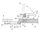
- FIG. 2 is an explanatory view (II-II cross-sectional view in FIG. 1) showing the member holding device according to the first embodiment.
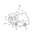
- FIG. 7 is a perspective view showing an arm portion in the member holding device according to the first embodiment.
- FIG. 7 is a perspective view showing an arm portion in the member holding device according to the first embodiment.
- FIG. 5 is an explanatory view showing a member holding device according to a first embodiment.
- FIG. 5 is an explanatory view showing a member holding device according to a first embodiment.
- FIG. 5 is an explanatory view showing a member holding device according to a first embodiment.
- FIG. 5 is an explanatory view showing a member holding device according to a first embodiment.
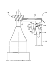
- FIG. 1 is a side view showing a machine tool provided with a member holding device according to a first embodiment.
- FIG. 1 is a plan view showing a machine tool provided with a member holding device according to a first embodiment. It is explanatory drawing which shows the example which applied the member holding
- the member holding device according to the present invention is adopted for a work transfer device in a hobbing machine, which facilitates setting work of a gripper for holding a work, such as a wrench or the like. It can be performed without using a tool.
- a work transfer device in a hobbing machine
- a gripper for holding a work
- a wrench such as a wrench
- the present invention is not limited to the following embodiments, and it goes without saying that various modifications can be made without departing from the scope of the present invention.
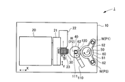
- a bed 10 is provided on a hobbing machine 1 which is a gear processing machine (machine tool), and on this bed 10, a column 20 moves in the horizontal X-axis direction It is supported possible.
- a saddle 21 is supported by the column 20 so as to be capable of moving up and down in the vertical Z-axis direction, and the hob head 22 is supported by the saddle 21 so as to be movable in the Y-axis direction orthogonal to the X-axis direction and the Z-axis direction.
- the hob main shaft 23 is rotatably supported by the hob head 22 about a horizontal hob rotation axis B.
- a hob cutter 30, which is a gear machining tool (machining tool), is provided. It is attached detachably.
- the hob cutter 30 can be moved in the X-axis direction, the Y-axis direction, and the Z-axis direction by driving the column 20, the saddle 21 and the hob head 22, and by rotating the hob main shaft 23 by the hob head 22, The hob cutter 30 can be rotated about the hob rotation axis B.
- a cylindrical table 40 is provided on the bed 10 so as to face the hob cutter 30 of the column 20, and the table 40 has a lower side for work clamping.
- the side work fixture 41 is rotatably supported around a vertical work rotation axis C1, and supported slidably in the direction of the axis (work rotation axis C1).
- a counter column 50 is provided on the opposite side of the column 20 sandwiching the table 40, and on the counter column 50, a tailstock 51 is provided on the upper side of the table 40.
- an upper work fixture 52 for work clamp is provided coaxially with the lower work fixture 41 of the table 40, is rotatable around the work rotation axis C1, and its axis (work rotation axis C1) is slidably supported in the direction.
- the workpiece W which is a workpiece external gear (a workpiece) is rotated about the workpiece rotation axis C1 so as to be vertically sandwiched by the lower workpiece fixture 41 and the upper workpiece fixture 52 for workpiece clamps. It is supposed to be supported.
- the counter column 50 is provided with a work turning device (work changer) 60 as a work transfer device for holding the work W and transferring the work W on the hobbing machine 1.
- a work turning device (work changer) 60 as a work transfer device for holding the work W and transferring the work W on the hobbing machine 1.
- a cylindrical portion 61 engaged with the counter column 50 and three arm portions (main body portions) 62 extending radially outward from the cylindrical portion 61 are supported rotatably around a vertical work turning axis C 2 ing.
- the three arm portions 62 are provided at equal angular intervals (120 ° in the present embodiment) in the circumferential direction of the cylindrical portion 61, and the tip end portion thereof is a loading position for loading the work W into the hobbing machine 1.
- P1 extends to a processing position P2 for performing gear processing on the workpiece W, and a delivery position P3 for unloading the processed workpiece W from the hobbing machine 1.
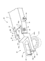
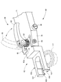
- a gripper (holding unit) 63 formed to match the shape and dimensions of the work W is detachably attached to the tip end of the arm 62. Therefore, the workpiece W is conveyed by the rotation of the cylindrical portion 61 in a state of being held by the gripper 63 in the workpiece turning device 60 (see FIGS. 1, 2, 7 and 8). That is, in the workpiece turning device 60, the workpiece W held by the tip end of the arm portion 62 via the gripper 63 rotates the cylindrical portion 61 to sequentially carry in the loading position P1, the processing position P2 and the unloading position P3. It is to be transported.
- the workpiece turning device 60 is provided with a member holding device according to the present invention.
- the member holding device includes a gripper (holding unit) 63 for holding the work W, and an arm unit (main body unit) 62 to which the gripper 63 is detachably mounted.
- Replacement that is, setup replacement can be performed without using a tool such as a wrench.
- a cover member 64 is provided at the connecting portion between the arm portion 62 and the gripper 63.
- the cover member 64 is fixed by screwing screw members 65 from both sides of the arm portion 62.
- the upper surface portion 64 a of the cover member 64 is provided to be inclined so that chips generated by the processing of the workpiece W do not accumulate.
- the upper surface portion 64a of the cover member 64 may be inclined, and the deposition of chips may be prevented by formation of a material having a small coefficient of friction, embossing, or the like.
- a gripper holding portion (groove portion) 62 a for holding the gripper 63 is provided at the tip end of the arm portion 62.
- the gripper holding portion 62a is a groove formed facing the tip end surface 70 and the upper surface 71 of the arm portion 62, and a bottom surface (third surface) extending in parallel (horizontally) with the upper surface 71 of the arm portion 62 72 and four side surfaces 73, 74, 75, 76 which extend upward (vertically) from the bottom surface 72 and connect to the top surface 71.
- the first side surface (first surface) 73 is formed orthogonal to the upper surface 71 of the arm portion 62 and along the extending direction of the arm portion 62 (left and right direction in FIG. 1 and FIG. 2) .
- the second side surface (second surface) 74 is orthogonal to the upper surface 71 of the arm 62 and orthogonal to the extending direction of the arm 62, that is, the upper surface 71 of the arm 62 and the first
- the two sides of the side surface 73 are formed to be orthogonal to each other.
- the first side surface 73 and the second side surface 74 are provided adjacent to each other, and a rectangular corner 77 is formed by the first side surface 73 and the second side surface 74.
- the corner portion 77 formed by the first side surface 73 and the second side surface 74 is indicated by a two-dot chain line. It shows.
- the distal end portion of the arm portion 62 is formed with a second screw hole 75a opening toward the first side surface 73 and the second side surface 74.
- a ball plunger (pressing means) 80 is attached to the second screw hole 75a.
- the ball plunger 80 is attached so that the spherical portion 81 at its tip projects from the third side surface 75 and faces the space of the groove 62a, and as shown in FIG.
- the mounting portion 63a of the gripper 63 accommodated in the groove portion 62a of the above is pressed with a predetermined pressing force F.
- the ball plunger 80 is a pressing means for pressing the mounting portion 63 a of the gripper 63 accommodated in the groove 62 a of the arm portion 62 against the first side surface 73 and the second side surface 74.
- the pressing direction of the ball plunger 80 may be any direction that allows the mounting portion 63 a of the gripper 63 to be pressed against the first side surface 73 and the second side surface 74.
- the direction in which the corner 77 formed by the first side surface 73 and the second side surface 74 is bisected as the pressing direction, that is, the pressing direction by the ball plunger 80 is the first side surface 73 and the The angle between the first side 73 and the second side 74 is substantially the same (the first side 73 and the second side 74 are directed to the corner 77 formed by the second side 74).
- the direction is 45 °).
- the gripper 63 can be positioned with respect to the arm portion 62 in two directions orthogonal to each other in the horizontal plane and in the vertical and horizontal directions in FIG.
- first side surface 73 and the second side surface 74 position the gripper 63 with respect to the arm portion 62 in two directions, they are not orthogonal to the upper surface 71 of the arm portion 62 as in this embodiment. It is good. Further, the first side surface 73 and the second side surface 74 do not have to be orthogonal to each other, and the corner 77 formed by the first side surface 73 and the second side surface 74 has an acute angle or an obtuse angle. good.
- the third side surface 75 in which the second screw hole 75a is opened and the outer side surface 79 of the arm portion 62 located on the back side of the third screw hole 75a are second screw so that the second screw hole 75a can be easily processed. It is formed to be orthogonal to the hole 75a. That is, the third side surface 75 is formed to extend in a direction different from the first side surface 73 and the second side surface 74 and to face the corner 77, and the outer side surface 79 is parallel to the third side surface 75. It is formed. Of course, the third side surface 75 and the outer side surface 79 may not be formed to be orthogonal to the second screw hole 75a, and the third side surface 75 and the outer side surface 79 may not be formed in parallel. .
- the bottom surface 72 of the groove 62a is orthogonal to the first side 73 and the second side 74 and the upper surface 71 of the arm 62 It is formed to extend in parallel (horizontal), and further, a first screw hole 72 a opened in the bottom surface 72 is formed.
- the first screw hole 72a is formed to be parallel to the mounting direction (vertical direction in FIG. 2) of the gripper 63 with respect to the arm portion 62, that is, to the four side surfaces 73, 74, 75, 76 and to be orthogonal to the bottom surface 72. ing.
- a screw portion 91 of a clamp member 90 described later is screwed into the first screw hole 72a.
- a fourth side surface 76 is formed in the groove portion 62 a of the arm portion 62 so as to face the second side surface 74 orthogonal to the extending direction of the arm portion 62. It comes to be secured securely.
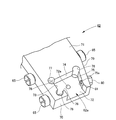
- the gripper 63 detachably mounted on the arm 62 is a mounting portion 63a for inserting into the groove 62a of the arm 62 described above and connecting it with the arm 62. And a holding portion 63 b which is formed in accordance with the shape and dimensions of the work W and holds the work W.
- the mounting portion 63a of the gripper 63 is formed in substantially the same shape as the groove 62a and slightly smaller than the groove 62a so that the mounting portion 63a of the gripper 62 can be inserted (accommodated) into the gripper holding portion 62a of the arm 62. It has an end face 100 (see FIG. 2) corresponding to the bottom surface 72 and four side faces 101, 102, 103, 104 (see FIG. 1) corresponding to the four side faces 73, 74, 75, 76 of the groove 62a. .
- the second surface 102 is formed along a direction perpendicular to the upper surface 105 of the gripper 63 and perpendicular to the extending direction of the gripper 63 so as to correspond to the second side surface 74 of the groove 62 a of the arm 62 ing.
- the first side surface 101 and the second side surface 102 are provided adjacent to each other, and the corner portion 106 is formed by the first side surface 101 and the second side surface 102.
- the corner 106 is at the same angle (90 °) as the corner 77 so as to correspond to the corner 77 of the groove 62 a of the arm 62.
- the third side surface 103 extends in a direction different from the first side surface 101 and the second side surface 102 so as to correspond to the third side surface 75 of the groove 62 a of the arm portion 62 and opposite to the corner 106. It is formed to turn to the side.
- the third side surface 103 is a ball plunger 80 attached to the arm portion 62 such that the attachment portion 63 a of the gripper 63 is pressed against the first side surface 73 and the second side surface 74 in the groove 62 a of the arm portion 62. What is necessary is just to be able to contact the spherical portion 81 of the above.
- the third side surface 103 does not contact the third side surface 75 of the groove 62 a of the arm 62 when the gripper 63 is attached to the arm 62, and the third side 75 and the third side 103 There may be a gap between them.
- the fourth side surface 104 is directed to the side opposite to the second side surface 104 orthogonal to the extending direction of the gripper 63 so as to correspond to the fourth side surface 76 in the groove 62 a of the arm portion 62. It is formed.
- the fourth side surface 104 is intended to reliably prevent the gripper 63 from coming off by being caught by the fourth side surface 76 in the groove 62 a of the arm 62 when the gripper 63 is attached to the arm 62. There may be a gap between the fourth side 76 and the fourth side 104 without contacting the fourth side 76.
- through holes for inserting screw portions 91 of a clamp member 90, which will be described later, into the attachment portions 63a of the gripper 63 at positions corresponding to the first screw holes 72a of the arm portion 62. 100a is provided. Therefore, by inserting the mounting portion 63a of the gripper 63 into the groove 62a of the arm 62, the screw 91 of the clamp member 90 is inserted into the through hole 100a and screwed into the first screw hole 72a of the arm 62.
- the gripper 63 and the arm 62 can be fixed.
- the clamp member 90 is in close contact with the gripper 63 by screwing the screw portion 91 screwed into the first screw hole 72 a of the arm portion 62 and the screw portion 91 into the first screw hole 72 a, and the gripper 63 is arm portion 62 And a cam lever 93 for switching the screw portion 91 to a rotatable or non-rotatable state with respect to the arm portion 62.
- the rotating portion 92 is formed to have a large diameter so that the operator can rotate the screw portion 91 and screw it into the first screw hole 72a without using a tool such as a wrench.
- the cam lever 93 is connected to the rotary unit 92 via a lock mechanism (not shown) so that the rotary unit 92 can be pressed against the arm unit 62 and the rotation of the rotary unit 92 can be locked.
- the workpiece holding portion 63b of the gripper 63 is provided with two claws 107 extending in parallel with the extending direction of the gripper 63, and in the claws 107, a scooping portion 108 for scooping the workpiece W is provided. It is provided.
- the inner portions of the two claws 107 and the scoop portion 108 are formed in accordance with the shape and dimensions of the work W, so that the work W can be reliably held and the work W can be transported to an accurate position. It has become.
- a relief portion 107a for avoiding interference with the deburring tool 111 in the deburring device 110 described later is formed. Therefore, the gear processing by the hob cutter 30 can be performed while the arm portion 62 transports the work W to the processing position, and the deburring processing by the deburring device 110 can be performed.
- the hobbing machine 1 is provided with the deburring device 110 for removing the burrs of the workpiece W located at the processing position P2 (see FIG. 8), and further measures the shape of the workpiece W located at the processing position P2
- a shape measuring device 120 is provided (see FIGS. 7 and 8). In FIG. 7, the deburring device 110 is omitted to make the drawing easy to see.
- the deburring apparatus 110 abuts the deburring tool 111 on one end surface of the workpiece W to remove burrs of the workpiece W.
- the deburring tool 111 is accommodated in the release portion 107a of the claw portion 107 so as not to interfere with the gripper 63 (FIG. 4, FIG. 5, see Figure 6).
- the shape measuring device 120 is provided so as to be located immediately below the gripper 63, and measures the shape of the workpiece W.
- the mounting portion 63 a of the gripper 63 is inserted into the groove portion 62 a of the arm portion 62.
- the spherical portion 81 of the ball plunger 80 projecting from the third side surface 75 in the groove 62a to the space of the groove 62a, the corner of the bottom 100 and the third side 103 in the mounting portion 63a.
- the parts are in contact, and the spherical part 81 of the ball plunger 80 is pushed outward (toward the outer side surface 79), and the mounting part 63a is accommodated in the groove 62a.
- the spherical surface portion 81 of the ball plunger 80 abuts on the third side surface 103 of the mounting portion 63a, and the pressing force F of the ball plunger 80 in the axial direction acts on the mounting portion 63a by the biasing force of the ball plunger 80.
- the mounting portion 63a is directed toward the corner 77 of the groove 62a such that the first side 101 and the second side 102 abut the first side 73 and the second side 74 of the groove 62a, respectively.
- the groove 62a is fitted. That is, the gripper 63 is positioned in two directions with respect to the arm portion 62.
- the arm portion 62 and the gripper 63 are fixed by the clamp member 90.
- the screw portion 91 of the clamp member 90 is inserted into the through hole 100a of the gripper 63, and the rotation portion 92 of the clamp member 90 is rotated to screw the screw portion 91 into the first screw hole 72a of the arm portion 62
- the portion 92 is brought into close contact with the gripper 63 and the gripper 63 is pressed against the arm portion 62.
- the gripper 63 is positioned in one direction (vertical direction) by fixing the end face 100 to the bottom surface 72 of the arm portion 62, and is fixed to the arm portion 62.
- the cam lever 93 of the clamp member 90 By operating the cam lever 93 of the clamp member 90, the screw portion 91 and the rotating portion 92 are switched to the non-rotatable state with respect to the arm portion 62, that is, the screw portion 91 and the rotating portion 92 are locked. Therefore, the arm portion 62 and the gripper 63 are securely fixed without the screw portion 91 of the clamp member 90 being loosened by vibration or the like.
- the cam lever 93 is capable of switching the screw portion 91 and the rotating portion 92 to a rotatable or non-rotatable state with respect to the arm portion 62.
- the cover member 64 is attached to the arm portion 62 in order to prevent contamination due to chips or cutting oil generated during processing.
- the cover member 64 does not have to be precisely attached to the arm 62, and the screw member 65 performs rough positioning and fixing.
- the screw member 65 does not require a tool or the like, and can be sufficiently detached from the arm portion 62 manually by the operator.
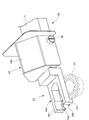
- the screw member 65 is turned by a worker's manual work to remove the cover member 64 (see FIG. 6).
- the mounting portion 63a of the gripper 63 is removed from the groove 62a of the arm 62 (see FIG. 4).
- the gripper 63 is accommodated in a state where it is pressed against the first side surface 73 and the second side surface 74 of the arm portion 62 by the ball plunger 80, but the biasing force F of the ball plunger 80 is horizontal. The operator can easily remove the gripper 63 in the removal direction (vertical direction) manually.
- the ball plunger 80 positions the gripper 63 and the arm 62 in two directions
- the clamp member 90 positions the gripper 63 and the arm 62 in one direction. Since positioning and fixing can be performed, the gripper 63 and the arm 62 in the workpiece turning device 60 can be connected with a simple structure, and the replacement of the gripper 63, that is, the setup replacement operation is facilitated and the working time is increased. It is possible to shorten and generalize any worker.
- the clamp member 90 can perform secure fixation without using a tool, that is, to achieve both toolless and secure fixation. Can.
- the holding structure of the gripper for holding the work has been described, but the member holding device according to the present invention is not limited to this.
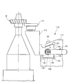
- the member holding device according to the present invention may be applied to the deburring device 110 in a machine tool.
- the deburring device 110 is a deburring cutter 111 for coming into contact with one end face of the workpiece W to remove burrs generated by processing, a cutter holding portion 112 for holding the deburring cutter, and the cutter holding portion And a main body 113 connected thereto.
- the main body portion 113 is provided with a groove portion 130 for attaching the cutter holding portion 112, and in the groove portion 130, a first side surface 131 and a second side surface 132 which are different in direction are formed. .
- the cutter holding portion 112 is provided with a mounting portion 140 for mounting to the main body portion 113, and in the mounting portion 140, the first side surface 141 and the second side surface 142 having different directions are provided.
- the grooves are formed to correspond to the first side surface 131 and the second side surface 132 of the groove 130 of the main body 113, respectively.
- the attachment portion 140 of the cutter holding portion 112 is inserted into the groove portion 130 of the main body portion 113, and the first side surface 141 and the second side surface 142 of the attachment portion 140 by the ball plunger 80 are respectively the first side surface of the groove portion 130 It is pressed toward the corner portion 133 so as to abut on the side surface 132 and the second side surface 132.
- the cutter holding portion 112 is pressed and fixed to the main body portion 113 by the clamp member 90, so that the cutter holding portion in the deburring device 110 without using a tool such as a wrench as in the work transfer device in the present embodiment. 112 can be replaced (setup replacement).
- the member holding device according to the present invention may be applied to a workpiece shape measuring device 120 in a machine tool.
- the workpiece shape measuring apparatus 120 includes a shape sensor 121 for measuring the shape of the workpiece W, a sensor holding portion 122 for holding the shape sensor 121, and a main portion 123 to which the sensor holding portion 122 is connected. There is.
- the main body portion 123 is provided with a groove portion 150 for attaching the sensor holding portion 122, and in the groove portion 150, a first side surface 151 and a second side surface 152 having different directions are formed. .
- the sensor holding portion 122 is provided with a mounting portion 160 for mounting to the main body portion 123, and in the mounting portion 160, the first side surface 161 and the second side surface 162 having different directions are provided. It is formed to correspond to the first side 151 and the second side 152 of the groove 150 of the main body 123, respectively.
- the attachment portion 160 of the sensor holding portion 122 is inserted into the groove portion 150 of the main body portion 123, and the first side surface 161 and the second side surface 162 of the attachment portion 160 by the ball plunger 80 are respectively the first side surface of the groove portion 150 It is pressed toward the corner 153 so as to abut on the second side 152 and the second side 152.
- the sensor holding portion 122 to the main body portion 123 by the clamp member 90, the sensor holding in the workpiece shape measuring device 120 without using a tool such as a wrench as in the workpiece conveying device in the present embodiment
- the part 122 can be replaced (setup replacement).
Landscapes
- Engineering & Computer Science (AREA)
- Mechanical Engineering (AREA)
- Robotics (AREA)
- Jigs For Machine Tools (AREA)
- Feeding Of Workpieces (AREA)
- Manipulator (AREA)
Priority Applications (3)
| Application Number | Priority Date | Filing Date | Title |
|---|---|---|---|
| US15/500,220 US10086486B2 (en) | 2014-08-21 | 2015-07-31 | Part-holding device and machine tool provided with said part-holding device |
| MX2017001429A MX2017001429A (es) | 2014-08-21 | 2015-07-31 | Dispositivo de retencion de partes y maquina-herramienta que se proporciona con dicho dispositivo de retencion de partes. |
| CN201580040950.XA CN107073664B (zh) | 2014-08-21 | 2015-07-31 | 构件保持装置以及具备该构件保持装置的机床 |
Applications Claiming Priority (2)
| Application Number | Priority Date | Filing Date | Title |
|---|---|---|---|
| JP2014168093A JP6356008B2 (ja) | 2014-08-21 | 2014-08-21 | 部材保持装置および当該部材保持装置を備えた工作機械 |
| JP2014-168093 | 2014-08-21 |
Publications (1)
| Publication Number | Publication Date |
|---|---|
| WO2016027642A1 true WO2016027642A1 (ja) | 2016-02-25 |
Family
ID=55350588
Family Applications (1)
| Application Number | Title | Priority Date | Filing Date |
|---|---|---|---|
| PCT/JP2015/071742 Ceased WO2016027642A1 (ja) | 2014-08-21 | 2015-07-31 | 部材保持装置および当該部材保持装置を備えた工作機械 |
Country Status (5)
| Country | Link |
|---|---|
| US (1) | US10086486B2 (enExample) |
| JP (1) | JP6356008B2 (enExample) |
| CN (1) | CN107073664B (enExample) |
| MX (1) | MX2017001429A (enExample) |
| WO (1) | WO2016027642A1 (enExample) |
Cited By (2)
| Publication number | Priority date | Publication date | Assignee | Title |
|---|---|---|---|---|
| CN112475966A (zh) * | 2020-11-12 | 2021-03-12 | 株洲瑞尔泰机电科技有限公司 | 一种新能源汽车车门生产用夹持装置 |
| AT527057A4 (de) * | 2023-08-23 | 2024-10-15 | Muser Ing Miguel | Palettengreifer |
Citations (3)
| Publication number | Priority date | Publication date | Assignee | Title |
|---|---|---|---|---|
| JPS60141445A (ja) * | 1983-12-27 | 1985-07-26 | Tanaka Kikinzoku Kogyo Kk | 紡糸口金の加工用位置決め治具 |
| JPH03142106A (ja) * | 1989-09-08 | 1991-06-17 | Iscar Ltd | 切削工具システム |
| JP2013510010A (ja) * | 2009-11-10 | 2013-03-21 | イスカーリミテッド | 切削工具アセンブリ |
Family Cites Families (16)
| Publication number | Priority date | Publication date | Assignee | Title |
|---|---|---|---|---|
| US590820A (en) * | 1897-09-28 | Richard a | ||
| US2546455A (en) * | 1947-10-06 | 1951-03-27 | Mcfall Co Carey | Cutting tool |
| US2685874A (en) * | 1951-11-08 | 1954-08-10 | Atlantic Refining Co | Safety attachment for pneumatic devices |
| US3475990A (en) * | 1968-01-16 | 1969-11-04 | Adam J Maximuk | Protective shield devices for tools and the like |
| JPS63229240A (ja) * | 1987-03-17 | 1988-09-26 | Kitamura Mach Co Ltd | パレツトチエンジヤ |
| SE9503867D0 (sv) * | 1995-11-02 | 1995-11-02 | Sandvik Ab | Fräsverktyg |
| IL154472A (en) * | 2003-02-16 | 2007-10-31 | Amir Satran | Cutting tool and cartridge therefor |
| IL157032A (en) * | 2003-07-21 | 2007-10-31 | Moshe Elbaz | Cutting head for rotary cutting tool |
| US6874773B1 (en) * | 2003-12-08 | 2005-04-05 | Modular indexing workholding system | |
| JP4220944B2 (ja) * | 2004-07-15 | 2009-02-04 | 三菱重工業株式会社 | 歯車研削盤 |
| IL166007A (en) * | 2004-12-27 | 2009-02-11 | Iscar Ltd | Deburring tool and cutting insert therefor |
| EP2060360B1 (en) * | 2006-09-04 | 2013-11-06 | Makino Milling Machine Co. Ltd. | Splash guard for machine tool |
| CN201107639Y (zh) * | 2007-11-30 | 2008-08-27 | 华南理工大学 | 应用机器视觉的大型在制工件几何测量装置 |
| CN101543916A (zh) * | 2009-04-28 | 2009-09-30 | 无锡银联机械有限公司 | 滚齿机用同步去毛刺装置 |
| EP2600998B1 (de) * | 2010-08-04 | 2018-10-10 | CeramTec GmbH | Schneidwerkzeug zum einstechen und stechdrehen |
| JP5760483B2 (ja) | 2011-02-17 | 2015-08-12 | 村田機械株式会社 | 搬送装置のチャック装置 |
-
2014
- 2014-08-21 JP JP2014168093A patent/JP6356008B2/ja active Active
-
2015
- 2015-07-31 CN CN201580040950.XA patent/CN107073664B/zh active Active
- 2015-07-31 MX MX2017001429A patent/MX2017001429A/es unknown
- 2015-07-31 WO PCT/JP2015/071742 patent/WO2016027642A1/ja not_active Ceased
- 2015-07-31 US US15/500,220 patent/US10086486B2/en active Active
Patent Citations (3)
| Publication number | Priority date | Publication date | Assignee | Title |
|---|---|---|---|---|
| JPS60141445A (ja) * | 1983-12-27 | 1985-07-26 | Tanaka Kikinzoku Kogyo Kk | 紡糸口金の加工用位置決め治具 |
| JPH03142106A (ja) * | 1989-09-08 | 1991-06-17 | Iscar Ltd | 切削工具システム |
| JP2013510010A (ja) * | 2009-11-10 | 2013-03-21 | イスカーリミテッド | 切削工具アセンブリ |
Cited By (4)
| Publication number | Priority date | Publication date | Assignee | Title |
|---|---|---|---|---|
| CN112475966A (zh) * | 2020-11-12 | 2021-03-12 | 株洲瑞尔泰机电科技有限公司 | 一种新能源汽车车门生产用夹持装置 |
| CN112475966B (zh) * | 2020-11-12 | 2023-03-10 | 上海优异达机电有限公司 | 一种新能源汽车车门生产用夹持装置 |
| AT527057A4 (de) * | 2023-08-23 | 2024-10-15 | Muser Ing Miguel | Palettengreifer |
| AT527057B1 (de) * | 2023-08-23 | 2024-10-15 | Muser Ing Miguel | Palettengreifer |
Also Published As
| Publication number | Publication date |
|---|---|
| US10086486B2 (en) | 2018-10-02 |
| US20170266773A1 (en) | 2017-09-21 |
| CN107073664A (zh) | 2017-08-18 |
| JP2016043435A (ja) | 2016-04-04 |
| MX2017001429A (es) | 2017-05-11 |
| CN107073664B (zh) | 2019-11-19 |
| JP6356008B2 (ja) | 2018-07-11 |
Similar Documents
| Publication | Publication Date | Title |
|---|---|---|
| JP5858887B2 (ja) | 加工装置 | |
| JP5836381B2 (ja) | ワークピースを移送するための保持装置 | |
| JP2008264983A (ja) | 5軸加工機用マシンバイス | |
| JP7025642B2 (ja) | 旋盤 | |
| JP5987654B2 (ja) | フェイスクランプチャックおよび工作機械 | |
| WO2016027642A1 (ja) | 部材保持装置および当該部材保持装置を備えた工作機械 | |
| CN1605430B (zh) | 夹具盘 | |
| JP5733255B2 (ja) | 加工機用の回転支持治具 | |
| JP2015054364A (ja) | 回転加工機用の刃具パレット及び回転加工機における刃具着脱方法 | |
| CN104736280B (zh) | 机床的内径车削附件 | |
| CN204053505U (zh) | 机床的工具保持件装拆结构 | |
| KR20180002311A (ko) | 선반용 척 조의 이동 장치 | |
| CN104289929A (zh) | 偏心夹紧夹具 | |
| JP5472719B2 (ja) | クランプ装置 | |
| JPH0526619B2 (enExample) | ||
| JP2009136938A (ja) | 主軸台旋回装置 | |
| JP5747061B2 (ja) | 回転加工機用のワーク支持治具及び回転加工機におけるワーク支持治具の着脱方法 | |
| JP4700436B2 (ja) | 刃物着脱用工具 | |
| JP3127357U (ja) | ツールホルダ | |
| TWI893338B (zh) | 把持具的製造方法 | |
| JP2015150649A (ja) | チャック装置 | |
| JP7173754B2 (ja) | ワーク保持用ブラケット | |
| KR200243357Y1 (ko) | 아버공구 클램프 구조 | |
| JP2005118889A (ja) | トルクレンチツール | |
| JP6671588B1 (ja) | 固定治具用ハンドル |
Legal Events
| Date | Code | Title | Description |
|---|---|---|---|
| 121 | Ep: the epo has been informed by wipo that ep was designated in this application |
Ref document number: 15833135 Country of ref document: EP Kind code of ref document: A1 |
|
| WWE | Wipo information: entry into national phase |
Ref document number: 15500220 Country of ref document: US |
|
| WWE | Wipo information: entry into national phase |
Ref document number: MX/A/2017/001429 Country of ref document: MX |
|
| NENP | Non-entry into the national phase |
Ref country code: DE |
|
| 122 | Ep: pct application non-entry in european phase |
Ref document number: 15833135 Country of ref document: EP Kind code of ref document: A1 |