WO2016013317A1 - 接合構造 - Google Patents
接合構造 Download PDFInfo
- Publication number
- WO2016013317A1 WO2016013317A1 PCT/JP2015/066667 JP2015066667W WO2016013317A1 WO 2016013317 A1 WO2016013317 A1 WO 2016013317A1 JP 2015066667 W JP2015066667 W JP 2015066667W WO 2016013317 A1 WO2016013317 A1 WO 2016013317A1
- Authority
- WO
- WIPO (PCT)
- Prior art keywords
- rib
- main surface
- long
- flange
- joining
- Prior art date
Links
Images


Classifications
-
- B—PERFORMING OPERATIONS; TRANSPORTING
- B62—LAND VEHICLES FOR TRAVELLING OTHERWISE THAN ON RAILS
- B62D—MOTOR VEHICLES; TRAILERS
- B62D25/00—Superstructure or monocoque structure sub-units; Parts or details thereof not otherwise provided for
- B62D25/20—Floors or bottom sub-units
-
- B—PERFORMING OPERATIONS; TRANSPORTING
- B62—LAND VEHICLES FOR TRAVELLING OTHERWISE THAN ON RAILS
- B62D—MOTOR VEHICLES; TRAILERS
- B62D29/00—Superstructures, understructures, or sub-units thereof, characterised by the material thereof
- B62D29/04—Superstructures, understructures, or sub-units thereof, characterised by the material thereof predominantly of synthetic material
- B62D29/046—Combined superstructure and frame, i.e. monocoque constructions
Definitions
- the present invention relates to a joining structure in which two members made of a fiber reinforced resin material are joined in a T shape.
- the joint between the side member and the cross member has a T-shaped joint structure.
- the side member is a member that extends in the vehicle front-rear direction
- the cross member is a member that extends in the vehicle width direction.
- Patent Document 1 discloses an example in which a side frame (side member) and a cross member are integrally formed by casting or the like.
- the side frame and the cross member constitute a T shape.
- the rigidity of the T-shaped part is improved.
- the rigidity of the T-shaped portion can be solidified by providing a rib as disclosed in the document.
- some of these skeleton members are made of a fiber reinforced resin material for the purpose of reducing the weight of the vehicle body. These include welding, etc. (including adhesion, ultrasonic welding, vibration welding, etc. ).
- Resin material has a lower specific gravity than metal materials such as iron and aluminum, but is inferior in mechanical properties.
- the fiber reinforced resin material is a material that supplements the mechanical characteristics with carbon fiber or glass fiber. Since the fiber reinforced resin material is more expensive than a general resin material, it is required to satisfy the required performance while suppressing the amount used.
- the present invention has been made in order to solve the above-described problems, and the object thereof is to provide a joint structure capable of improving the rigidity against torsional load in a structure in which a member made of a fiber reinforced resin material is joined in a T shape. Is to provide.
- the joining structure according to the present invention includes a long first member made of a fiber reinforced resin material and extending in the first direction, and a second structure made of a fiber reinforced resin material and perpendicular to the first direction.
- a joining structure for joining a long second member extending, the first member having a flat first main surface extending in the first direction, and extending in the first direction and perpendicular to the first main surface.
- the first member has an L-shaped cross-sectional shape, and the second member is adjacent to the first main surface and extends in the second direction.
- a main surface is provided, and on both sides of the second main surface in the first direction, there are provided vertical wall surfaces extending in the second direction and perpendicular to the second main surface, and the second member has a U-shape.
- a flange that abuts against the first main surface is provided at a second direction end of the second main surface, and the first main surface has a transverse cross-sectional shape.
- the flange is joined at at least one joint, so that the first member and the second member have a T-shaped joint structure, and the back surface of the first main surface has at least one
- a long rib is provided, and the long rib extends along the first direction in a direction intersecting the second direction, and is disposed so as to overlap the joining portion, and has a length in a direction away from the back surface. Also, the length in the direction along the first direction is increased.
- an inner rib is provided on the back surface of the second main surface and the vertical wall surface so as to follow the U-shaped cross-sectional shape,
- the first member is disposed at a position adjacent to the first member.
- the flange extends along the first direction
- the long rib extends on a boundary between a longitudinal end of the flange and the first main surface. Beyond that, it extends in the first direction.
- the bonding structure according to the present invention at least two of the bonding portions are arranged on the back surface at intervals in the first direction, and the long ribs overlap the bonding portions. As described above, the first direction is spaced apart.
- the inner rib is an X-shaped rib in which two plate members intersect to form an X-shape, and the side wall surface of the first member and the first rib A corner portion is constituted by the vertical wall surfaces of the two members, and the X-shaped ribs are arranged so as to be adjacent to the corner portion.
- the long rib is provided on the first main surface so that the long rib passes through the joint and along the rotation direction of the first member, thereby suppressing stress concentration around the joint. , Deformation can be suppressed.
- a predetermined load is input from the second member, a bending moment is generated in the first member.
- the deformation in the flange can be suppressed by increasing the rigidity in the vicinity of the joint portion of the second member on the input side and suppressing the deformation. Therefore, it is possible to more reliably transmit the load from the second member to the first member, and it is possible to reduce the stress generated in the joint portion.
- the effect of suppressing deformation around the joint portion is improved by extending the long rib to the outside of the longitudinal end of the flange, and the contact area by the flange is increased. It is possible to reduce stress concentration. Thereby, it becomes possible to disperse the stress over a wide area, and it is possible to suppress a decrease in strength and rigidity.
- joint structure according to the present invention when there are two joint portions, it is possible to reduce the number of members by arranging the long ribs in a necessary range (part), and the material of the members Use can be suppressed.
- the rigidity against the torsion of the second member is increased, and the deformation generated in the joining portion is more reliably reduced. can do. Furthermore, it is possible to alleviate locally high stresses and deformations that occur at the joint by making the load distribution to the first member more reliable.
- the stress generated by the twisting is caused by the long rib of the second member by interlocking the long rib on the first member and the X-shaped rib on the second member. It becomes possible to disperse effectively depending on the direction.
- the joining structure according to the present invention includes two members (a first member and a second member), and a longitudinal end of the second member is joined to a longitudinal side portion of the first member to form a T shape.
- Structure In the following first and second embodiments, an example of a structure in which the cross member 20 constituting the skeleton of the vehicle body is connected to the side member 10 will be described. That is, an example in which the first member is the side member 10 and the second member is the cross member 20 will be described.
- the side member 10 of this embodiment is a member which comprises the frame
- the side member 10 in this example is formed of a fiber reinforced resin material.
- the cross member 20 is a member constituting the skeleton of the vehicle body, like the side member 10.
- the cross member 20 is a member that extends in the vehicle width direction, and is joined to a side portion of the side member 10.
- the resin material has a lower specific gravity than metal materials such as iron and aluminum, but is inferior in mechanical properties.
- the fiber-reinforced resin material is a material that compensates for inferior mechanical properties with carbon fiber or glass fiber.
- a glass fiber such as GFRP (Glass fiber reinforced plastics) or a carbon fiber such as CFRP is used.
- the side member 10, the cross member 20, and the floor panel 35 are joined by bonding with an adhesive, ultrasonic welding, vibration welding, or the like.
- one side member 10 is a member that is disposed on the outer side in the vehicle width direction and extends in the vehicle front-rear direction.
- the side member 10 includes a first upper wall portion 11, an inner wall portion 12, and an outer wall portion 13.
- a first upper surface 11 a extending horizontally is formed on the first upper wall portion 11.
- the inner wall portion 12 is disposed on the inner side in the vehicle width direction of the first upper wall portion 11, and an inner wall surface 12a perpendicular to the first upper surface 11a is formed.
- an outer wall portion 13 is provided on the outer side in the vehicle width direction of the first upper wall portion 11.
- An L-shaped cross-sectional shape is formed by the first upper wall portion 11 and the inner wall portion 12.
- the first upper wall portion 11, the inner wall portion 12, and the outer wall portion 13 form a U-shaped cross-sectional shape that opens downward in the vehicle.
- the cross member 20 is a member extending in the vehicle width direction, and the outer end in the vehicle width direction is connected to the first upper wall portion 11 and the inner wall portion 12 of the side member 10. Connection will be described later.
- the cross member 20 has a second upper wall portion 21 and two vertical wall portions (a front vertical wall portion 22 and a rear vertical wall portion 23).
- a second upper surface 21 a extending horizontally is formed on the second upper wall portion 21.
- the front vertical wall portion 22 is disposed on the vehicle front portion of the second upper wall portion 21, and a front vertical wall surface 22a perpendicular to the second upper surface 21a is formed.
- the rear vertical wall portion 23 is disposed at the rear of the vehicle on the second upper wall portion 21, and a rear vertical wall surface 23a perpendicular to the second upper surface 21a is formed.
- the second upper wall portion 21, the front vertical wall portion 22, and the rear vertical wall portion 23 form a U-shaped cross-sectional shape that opens downward from the vehicle.
- a flange 25 protruding outward in the vehicle width direction is provided at the outer end in the vehicle width direction of the second upper surface 21a.
- the flange 25 extends from the end of the second upper surface 21a in the vehicle width direction so as to be continuous with the second upper surface 21a, and contacts the first upper surface 11a of the side member 10.
- the flange 25 has a substantially rectangular shape extending in the vehicle front-rear direction.
- the flange 25 protrudes forward of the vehicle from the front end of the second upper surface 21a and protrudes rearward of the vehicle rear end.
- the first upper surface 11 a and the flange 25 are joined by two joining portions 30. These joint portions 30 are provided at intervals in the vehicle front-rear direction. The joining is performed by bonding with an adhesive, ultrasonic welding, vibration welding, or the like as described above.
- a contact portion 24 that contacts the inner wall surface 12a of the side member 10 is provided on the outer side in the vehicle width direction of the front vertical wall portion 22 and the rear vertical wall portion 23 .
- the contact portion 24 and the inner wall surface 12a are joined.
- the joining is performed by an adhesive, ultrasonic welding, vibration welding, or the like, similarly to the joining of the flange 25 and the first upper surface 11a.
- illustration of a junction part is abbreviate
- a lower flange is provided at the vehicle lower part of the side member 10 and the cross member, and the lower flange is welded to the floor panel 35 as described above (adhesion with an adhesive, ultrasonic welding, vibration welding, etc.). Included.)
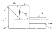
- first long rib 15a and second long rib 15b are provided on the back surface of the first upper surface 11a.
- the 1st long rib 15a and the 2nd long rib 15b are extended along the longitudinal direction (vehicle front-back direction) of the side member 10, and are arrange
- the first long rib 15a is disposed so as to overlap the joint portion 30 on the vehicle front side
- the second long rib 15b is disposed so as to overlap the joint portion 30 on the vehicle rear side.
- illustration of the floor panel 35 is abbreviate
- the vehicle longitudinal direction length is configured to be longer than the height of the first long rib 15a and the height of the second long rib 15b.
- the height is a length in a direction away from the rear surface of the first upper surface 11a of the side member 10 to the vehicle lower side, and is a vehicle vertical direction length.
- the first long rib 15a starts from the joint 30 on the vehicle front side (upper side in FIG. 3), passes through the boundary between the vehicle front end of the flange 25 and the first upper surface 11a, and extends toward the vehicle front.
- the second long rib 15b starts from the joint portion on the rear side of the vehicle (the lower side in FIG. 3), passes through the boundary between the rear end of the flange 25 and the first upper surface 11a, and extends toward the rear of the vehicle. .
- first long rib 15a and the second long rib 15b are slightly inclined outward in the vehicle width direction with respect to the vehicle longitudinal direction.
- the 1st long rib 15a inclines in the direction (vehicle width direction outer side) which leaves
- the second long rib 15b is inclined in the direction away from the cross member 20 (outward in the vehicle width direction) as it is away from the joint portion 30 (as it goes toward the rear of the vehicle).
- the first long ribs 15a and the like may be disposed along the longitudinal direction of the side member 10.
- the angle formed between the longitudinal direction of the cross member 20 (the vehicle width direction) and the longitudinal direction of the first long rib 15a, and the angle formed forward of the vehicle in the vehicle width direction is from 90 degrees (vertical) to 135 degrees. Good degree.
- the angle formed between the longitudinal direction of the cross member 20 (the vehicle width direction) and the longitudinal direction of the second long rib 15b and the angle formed on the vehicle rear side in the vehicle width direction is from 90 degrees (vertical) to 135 degrees. Good degree. That is, the angle ⁇ shown in FIG. 4 is preferably about 90 degrees ( ⁇ 1) to about 135 degrees ( ⁇ 2).
- the angle (alpha) may be about 45 degree
- An X-shaped rib 26 is provided on the back surface of the second upper surface 21 a of the cross member 20.
- the X-shaped rib 26 forms an X-shape when viewed from above the vehicle by intersecting two plates.
- the X-shaped rib 26 is disposed in the vicinity of the joint where the cross member 20 is joined to the side member 10.
- a front corner portion 22 b is configured by the inner wall surface 12 a of the side member 10 and the front vertical wall surface 22 a of the cross member 20.
- a front corner portion 22b is configured by the contact portion 24 of the cross member 20 and the front vertical wall surface 22a.
- a rear corner portion 23b is formed by the inner wall surface 12a (contact portion 24) and the rear vertical wall surface 23a.
- the X-shaped rib 26 is disposed adjacent to the front corner 22b and the rear corner 23b.
- a joint 30 is disposed on the extension line when extending in the longitudinal direction (cross direction) of the plate material constituting the X-shaped rib 26 from the end portion of the X-shaped rib 26 closer to the side member 10.
- the extension line is a line extending in the direction of opening outward in the vehicle width direction (downward in FIG. 5) when the X-shaped rib 26 is viewed from above the vehicle, as indicated by a one-dot chain line X in FIG.
- the first long rib 15a and the second long rib 15b pass through the joint portion 30 and the first long rib 15a and the like are arranged along the rotation direction of the side member 10.
- the flat surface on the back side of the upper surface 11a it is possible to suppress the concentration of stress around the joint portion 30 and to suppress deformation.
- a bending moment is generated in the side member 10.
- the side member 10 with long ribs substantially perpendicular to the longitudinal direction of the cross member 20 the rigidity with respect to the bending moment of the joint between the side member 10 and the cross member 20 is increased, and the side member 10 and the cross member 20 are perpendicular to each other. It is possible to improve the strength and rigidity against bending in any direction (vehicle up-down direction).
- the cross member 20 is provided with the X-shaped ribs 26 and the like, so that the rigidity in the vicinity of the joint portion of the cross member 20 on the input side is increased and the deformation is suppressed. Deformation can be suppressed. Thereby, the transmission of the load from the cross member 20 to the side member 10 can be more reliably performed, and the stress generated in the joint portion can be reduced.
- the deformation around the joint portion 30 can be further suppressed, the contact area by the flange 25 can be increased, and the stress concentration can be increased. Can be relaxed. Thereby, it becomes possible to disperse the stress over a wide area, and it is possible to suppress a decrease in strength and rigidity.
- the long rib 15a and the second long rib 15b are arranged in the two joint portions 30, respectively, the long rib can be arranged in a necessary range, and the member Reduction is possible, and the use of the material of the member can be suppressed.
- the rigidity of the cross member 20 against torsion can be increased, and the deformation generated in the joint portion can be more reliably reduced. Furthermore, by making the distribution of the load to the side member 10 more reliable, it becomes possible to relieve locally high stress and deformation generated in the joint portion 30.
- the stress generated by torsion is effectively controlled in the longitudinal direction (vehicle width direction) of the cross member 20. Can be dispersed.
- the second embodiment will be described with reference to FIG.
- the present embodiment is a modification of the first embodiment (FIGS. 1 to 5), and the same or similar parts as in the first embodiment are denoted by the same reference numerals, and redundant description is omitted. .
- a U-shaped rib 29 is provided inside the cross member 20.
- the U-shaped rib 29 is composed of a rectangular plate attached to the back surfaces of the second upper surface 21a, the front vertical wall surface 22a, and the rear vertical wall surface 23a.
- the U-shaped rib 29 may be disposed in the vicinity of the joint portion, similarly to the X-shaped rib 26.
- the rigidity in the vicinity of the joint portion of the cross member 20 on the input side is increased.
- the deformation generated in the flange 25 can be suppressed.
- the transmission of the load from the cross member 20 to the side member 10 can be more reliably performed, and the stress generated in the joint portion can be reduced.
- the 1st long rib 15a and the 2nd long rib 15b are each extended from the junction part 30 as a starting point, it is not restricted to this.
- the first long ribs 15 a and the second long ribs 15 b may extend so as to pass through the bonding regions of the bonding portions 30 and straddle the bonding portions 30.
- the U-shaped rib 29 described in the second embodiment may be combined with the X-shaped rib 26 described in the first embodiment.
- the cross member 20 or the like has a U-shaped cross section that opens downward in the vehicle, but may be configured to open upward.
- the joining of the side member 10 and the cross member 20 which are members constituting the vehicle body has been described, but the present invention is not limited to this.
- the present invention can be applied to a structure in which a center pillar and a side sill are joined, a structure in which a front pillar and a front side member are joined, and the like.
- the joining structure according to the present invention is not limited to the members constituting the vehicle body, and can be applied to a structure in which two members are joined in a T shape.
- Second upper wall portion 21a Second upper surface 22 Front vertical wall portion 22a Front vertical wall surface 22b Front corner portion 23 Back vertical wall portion 23a Back vertical wall surface 23b Rear corner portion 24 Contact portion 25 Flange 26 X-shaped rib 29 Shaped rib 30 joint 35 floor panel
Landscapes
- Engineering & Computer Science (AREA)
- Chemical & Material Sciences (AREA)
- Combustion & Propulsion (AREA)
- Transportation (AREA)
- Mechanical Engineering (AREA)
- Architecture (AREA)
- Structural Engineering (AREA)
- Body Structure For Vehicles (AREA)
Priority Applications (2)
| Application Number | Priority Date | Filing Date | Title |
|---|---|---|---|
| DE112015000130.1T DE112015000130B4 (de) | 2014-07-23 | 2015-06-10 | Verbindungsstruktur |
| CN201580001672.7A CN105492303B (zh) | 2014-07-23 | 2015-06-10 | 接合构造 |
Applications Claiming Priority (2)
| Application Number | Priority Date | Filing Date | Title |
|---|---|---|---|
| JP2014-149783 | 2014-07-23 | ||
| JP2014149783A JP6331823B2 (ja) | 2014-07-23 | 2014-07-23 | 接合構造 |
Publications (1)
| Publication Number | Publication Date |
|---|---|
| WO2016013317A1 true WO2016013317A1 (ja) | 2016-01-28 |
Family
ID=55162853
Family Applications (1)
| Application Number | Title | Priority Date | Filing Date |
|---|---|---|---|
| PCT/JP2015/066667 WO2016013317A1 (ja) | 2014-07-23 | 2015-06-10 | 接合構造 |
Country Status (4)
| Country | Link |
|---|---|
| JP (1) | JP6331823B2 (zh) |
| CN (1) | CN105492303B (zh) |
| DE (1) | DE112015000130B4 (zh) |
| WO (1) | WO2016013317A1 (zh) |
Cited By (1)
| Publication number | Priority date | Publication date | Assignee | Title |
|---|---|---|---|---|
| US10583629B2 (en) * | 2015-02-06 | 2020-03-10 | Kobe Steel, Ltd. | Joining structure |
Families Citing this family (1)
| Publication number | Priority date | Publication date | Assignee | Title |
|---|---|---|---|---|
| KR20200096973A (ko) * | 2018-02-26 | 2020-08-14 | 미쯔이가가꾸가부시끼가이샤 | 이재 접합체 및 전자 부품 수납용 하우징 |
Citations (5)
| Publication number | Priority date | Publication date | Assignee | Title |
|---|---|---|---|---|
| JP2001130449A (ja) * | 1999-09-15 | 2001-05-15 | Valeo Thermique Moteur | 複合構造体、特に自動車用フロントフェース支持体として好適に使用しうる複合構造体 |
| JP2003211548A (ja) * | 2001-10-08 | 2003-07-29 | Bayer Ag | 複合構造部材、該複合構造部材からなる製品および乗物用構造構成部材 |
| JP2011143762A (ja) * | 2010-01-12 | 2011-07-28 | Toyota Motor Corp | 車両骨格構造 |
| WO2013080975A1 (ja) * | 2011-11-28 | 2013-06-06 | 帝人株式会社 | 耐衝撃部材 |
| JP2013141848A (ja) * | 2012-01-10 | 2013-07-22 | Honda Motor Co Ltd | 自動車の車体フレーム構造 |
Family Cites Families (7)
| Publication number | Priority date | Publication date | Assignee | Title |
|---|---|---|---|---|
| JPH06321138A (ja) | 1993-05-10 | 1994-11-22 | Mazda Motor Corp | 自動車の車体構造 |
| DE102008020527A1 (de) | 2008-04-24 | 2009-10-29 | GM Global Technology Operations, Inc., Detroit | Rahmenstruktur für ein Kraftfahrzeug |
| US8262155B2 (en) | 2009-12-06 | 2012-09-11 | Honda Motor Co., Ltd. | Overmolded joint for beam assembly |
| JP2011143761A (ja) * | 2010-01-12 | 2011-07-28 | Toyota Motor Corp | 車体側部構造 |
| JP5246300B2 (ja) * | 2011-06-14 | 2013-07-24 | Jfeスチール株式会社 | 車体側部構造 |
| DE102011108156A1 (de) | 2011-07-20 | 2013-01-24 | Daimler Ag | Verbindungsstruktur für einen Kraftwagen und Verfahren zu deren Herstellung |
| US20150061320A1 (en) * | 2012-01-10 | 2015-03-05 | Honday Motor Co., Ltd. | Vehicle body frame structure of motor vehicle |
-
2014
- 2014-07-23 JP JP2014149783A patent/JP6331823B2/ja active Active
-
2015
- 2015-06-10 WO PCT/JP2015/066667 patent/WO2016013317A1/ja active Application Filing
- 2015-06-10 CN CN201580001672.7A patent/CN105492303B/zh not_active Expired - Fee Related
- 2015-06-10 DE DE112015000130.1T patent/DE112015000130B4/de active Active
Patent Citations (5)
| Publication number | Priority date | Publication date | Assignee | Title |
|---|---|---|---|---|
| JP2001130449A (ja) * | 1999-09-15 | 2001-05-15 | Valeo Thermique Moteur | 複合構造体、特に自動車用フロントフェース支持体として好適に使用しうる複合構造体 |
| JP2003211548A (ja) * | 2001-10-08 | 2003-07-29 | Bayer Ag | 複合構造部材、該複合構造部材からなる製品および乗物用構造構成部材 |
| JP2011143762A (ja) * | 2010-01-12 | 2011-07-28 | Toyota Motor Corp | 車両骨格構造 |
| WO2013080975A1 (ja) * | 2011-11-28 | 2013-06-06 | 帝人株式会社 | 耐衝撃部材 |
| JP2013141848A (ja) * | 2012-01-10 | 2013-07-22 | Honda Motor Co Ltd | 自動車の車体フレーム構造 |
Cited By (1)
| Publication number | Priority date | Publication date | Assignee | Title |
|---|---|---|---|---|
| US10583629B2 (en) * | 2015-02-06 | 2020-03-10 | Kobe Steel, Ltd. | Joining structure |
Also Published As
| Publication number | Publication date |
|---|---|
| JP2016022881A (ja) | 2016-02-08 |
| CN105492303B (zh) | 2017-10-20 |
| JP6331823B2 (ja) | 2018-05-30 |
| DE112015000130B4 (de) | 2019-03-14 |
| DE112015000130T5 (de) | 2016-04-28 |
| CN105492303A (zh) | 2016-04-13 |
Similar Documents
| Publication | Publication Date | Title |
|---|---|---|
| JP6122969B2 (ja) | 車体上部構造 | |
| JP5963060B2 (ja) | 車体後部のフロア構造 | |
| WO2012121142A1 (ja) | 車体後部構造 | |
| WO2015087782A1 (ja) | 車両の側部車体構造 | |
| JP2008105561A (ja) | 車両前部構造 | |
| JP5998453B2 (ja) | リヤストラット部の補強構造 | |
| JP4096940B2 (ja) | 車体後部構造 | |
| JP5695556B2 (ja) | 自動車のキャビン構造 | |
| KR101558745B1 (ko) | 차량의 언더플로어 프레임 시스템 | |
| WO2008068860A1 (ja) | 鉄道車両の構体骨構造 | |
| JP4440832B2 (ja) | 鉄道車両の構体骨構造 | |
| JP6379791B2 (ja) | 接合構造 | |
| JP6331823B2 (ja) | 接合構造 | |
| JP5686586B2 (ja) | 自動車用車体骨格における補強構造 | |
| JP5978078B2 (ja) | 鉄道車両用車体 | |
| JP2011194945A (ja) | 車両側部結合部構造 | |
| JP6232987B2 (ja) | 車体樹脂パネル構造 | |
| JP5277053B2 (ja) | 車体フレーム構造 | |
| KR101575456B1 (ko) | 차량의 언더플로어 프레임 시스템 | |
| JP6318988B2 (ja) | 車両上部構造 | |
| JP6399040B2 (ja) | 車体の接合構造 | |
| JP6311989B2 (ja) | 接合構造 | |
| WO2015076023A1 (ja) | 車体後部構造 | |
| JP4960726B2 (ja) | 自動車のサイドシル | |
| JP5799900B2 (ja) | 車両前部構造 |
Legal Events
| Date | Code | Title | Description |
|---|---|---|---|
| WWE | Wipo information: entry into national phase |
Ref document number: 201580001672.7 Country of ref document: CN |
|
| WWE | Wipo information: entry into national phase |
Ref document number: 112015000130 Country of ref document: DE |
|
| 121 | Ep: the epo has been informed by wipo that ep was designated in this application |
Ref document number: 15823968 Country of ref document: EP Kind code of ref document: A1 |
|
| 122 | Ep: pct application non-entry in european phase |
Ref document number: 15823968 Country of ref document: EP Kind code of ref document: A1 |