WO2016009598A1 - 表示装置 - Google Patents
表示装置 Download PDFInfo
- Publication number
- WO2016009598A1 WO2016009598A1 PCT/JP2015/003195 JP2015003195W WO2016009598A1 WO 2016009598 A1 WO2016009598 A1 WO 2016009598A1 JP 2015003195 W JP2015003195 W JP 2015003195W WO 2016009598 A1 WO2016009598 A1 WO 2016009598A1
- Authority
- WO
- WIPO (PCT)
- Prior art keywords
- display
- display unit
- display device
- light source
- decorative member
- Prior art date
- Legal status (The legal status is an assumption and is not a legal conclusion. Google has not performed a legal analysis and makes no representation as to the accuracy of the status listed.)
- Ceased
Links
Images



Classifications
-
- G—PHYSICS
- G02—OPTICS
- G02F—OPTICAL DEVICES OR ARRANGEMENTS FOR THE CONTROL OF LIGHT BY MODIFICATION OF THE OPTICAL PROPERTIES OF THE MEDIA OF THE ELEMENTS INVOLVED THEREIN; NON-LINEAR OPTICS; FREQUENCY-CHANGING OF LIGHT; OPTICAL LOGIC ELEMENTS; OPTICAL ANALOGUE/DIGITAL CONVERTERS
- G02F1/00—Devices or arrangements for the control of the intensity, colour, phase, polarisation or direction of light arriving from an independent light source, e.g. switching, gating or modulating; Non-linear optics
- G02F1/01—Devices or arrangements for the control of the intensity, colour, phase, polarisation or direction of light arriving from an independent light source, e.g. switching, gating or modulating; Non-linear optics for the control of the intensity, phase, polarisation or colour
- G02F1/13—Devices or arrangements for the control of the intensity, colour, phase, polarisation or direction of light arriving from an independent light source, e.g. switching, gating or modulating; Non-linear optics for the control of the intensity, phase, polarisation or colour based on liquid crystals, e.g. single liquid crystal display cells
- G02F1/133—Constructional arrangements; Operation of liquid crystal cells; Circuit arrangements
- G02F1/1333—Constructional arrangements; Manufacturing methods
- G02F1/1335—Structural association of cells with optical devices, e.g. polarisers or reflectors
- G02F1/1336—Illuminating devices
- G02F1/133602—Direct backlight
- G02F1/133606—Direct backlight including a specially adapted diffusing, scattering or light controlling members
-
- B—PERFORMING OPERATIONS; TRANSPORTING
- B60—VEHICLES IN GENERAL
- B60K—ARRANGEMENT OR MOUNTING OF PROPULSION UNITS OR OF TRANSMISSIONS IN VEHICLES; ARRANGEMENT OR MOUNTING OF PLURAL DIVERSE PRIME-MOVERS IN VEHICLES; AUXILIARY DRIVES FOR VEHICLES; INSTRUMENTATION OR DASHBOARDS FOR VEHICLES; ARRANGEMENTS IN CONNECTION WITH COOLING, AIR INTAKE, GAS EXHAUST OR FUEL SUPPLY OF PROPULSION UNITS IN VEHICLES
- B60K35/00—Instruments specially adapted for vehicles; Arrangement of instruments in or on vehicles
- B60K35/20—Output arrangements, i.e. from vehicle to user, associated with vehicle functions or specially adapted therefor
-
- B—PERFORMING OPERATIONS; TRANSPORTING
- B60—VEHICLES IN GENERAL
- B60K—ARRANGEMENT OR MOUNTING OF PROPULSION UNITS OR OF TRANSMISSIONS IN VEHICLES; ARRANGEMENT OR MOUNTING OF PLURAL DIVERSE PRIME-MOVERS IN VEHICLES; AUXILIARY DRIVES FOR VEHICLES; INSTRUMENTATION OR DASHBOARDS FOR VEHICLES; ARRANGEMENTS IN CONNECTION WITH COOLING, AIR INTAKE, GAS EXHAUST OR FUEL SUPPLY OF PROPULSION UNITS IN VEHICLES
- B60K35/00—Instruments specially adapted for vehicles; Arrangement of instruments in or on vehicles
- B60K35/20—Output arrangements, i.e. from vehicle to user, associated with vehicle functions or specially adapted therefor
- B60K35/21—Output arrangements, i.e. from vehicle to user, associated with vehicle functions or specially adapted therefor using visual output, e.g. blinking lights or matrix displays
- B60K35/215—Output arrangements, i.e. from vehicle to user, associated with vehicle functions or specially adapted therefor using visual output, e.g. blinking lights or matrix displays characterised by the combination of multiple visual outputs, e.g. combined instruments with analogue meters and additional displays
-
- B—PERFORMING OPERATIONS; TRANSPORTING
- B60—VEHICLES IN GENERAL
- B60K—ARRANGEMENT OR MOUNTING OF PROPULSION UNITS OR OF TRANSMISSIONS IN VEHICLES; ARRANGEMENT OR MOUNTING OF PLURAL DIVERSE PRIME-MOVERS IN VEHICLES; AUXILIARY DRIVES FOR VEHICLES; INSTRUMENTATION OR DASHBOARDS FOR VEHICLES; ARRANGEMENTS IN CONNECTION WITH COOLING, AIR INTAKE, GAS EXHAUST OR FUEL SUPPLY OF PROPULSION UNITS IN VEHICLES
- B60K35/00—Instruments specially adapted for vehicles; Arrangement of instruments in or on vehicles
- B60K35/20—Output arrangements, i.e. from vehicle to user, associated with vehicle functions or specially adapted therefor
- B60K35/21—Output arrangements, i.e. from vehicle to user, associated with vehicle functions or specially adapted therefor using visual output, e.g. blinking lights or matrix displays
- B60K35/22—Display screens
-
- B—PERFORMING OPERATIONS; TRANSPORTING
- B60—VEHICLES IN GENERAL
- B60K—ARRANGEMENT OR MOUNTING OF PROPULSION UNITS OR OF TRANSMISSIONS IN VEHICLES; ARRANGEMENT OR MOUNTING OF PLURAL DIVERSE PRIME-MOVERS IN VEHICLES; AUXILIARY DRIVES FOR VEHICLES; INSTRUMENTATION OR DASHBOARDS FOR VEHICLES; ARRANGEMENTS IN CONNECTION WITH COOLING, AIR INTAKE, GAS EXHAUST OR FUEL SUPPLY OF PROPULSION UNITS IN VEHICLES
- B60K35/00—Instruments specially adapted for vehicles; Arrangement of instruments in or on vehicles
- B60K35/20—Output arrangements, i.e. from vehicle to user, associated with vehicle functions or specially adapted therefor
- B60K35/29—Instruments characterised by the way in which information is handled, e.g. showing information on plural displays or prioritising information according to driving conditions
-
- B—PERFORMING OPERATIONS; TRANSPORTING
- B60—VEHICLES IN GENERAL
- B60K—ARRANGEMENT OR MOUNTING OF PROPULSION UNITS OR OF TRANSMISSIONS IN VEHICLES; ARRANGEMENT OR MOUNTING OF PLURAL DIVERSE PRIME-MOVERS IN VEHICLES; AUXILIARY DRIVES FOR VEHICLES; INSTRUMENTATION OR DASHBOARDS FOR VEHICLES; ARRANGEMENTS IN CONNECTION WITH COOLING, AIR INTAKE, GAS EXHAUST OR FUEL SUPPLY OF PROPULSION UNITS IN VEHICLES
- B60K35/00—Instruments specially adapted for vehicles; Arrangement of instruments in or on vehicles
- B60K35/50—Instruments characterised by their means of attachment to or integration in the vehicle
- B60K35/53—Movable instruments, e.g. slidable
-
- B—PERFORMING OPERATIONS; TRANSPORTING
- B60—VEHICLES IN GENERAL
- B60K—ARRANGEMENT OR MOUNTING OF PROPULSION UNITS OR OF TRANSMISSIONS IN VEHICLES; ARRANGEMENT OR MOUNTING OF PLURAL DIVERSE PRIME-MOVERS IN VEHICLES; AUXILIARY DRIVES FOR VEHICLES; INSTRUMENTATION OR DASHBOARDS FOR VEHICLES; ARRANGEMENTS IN CONNECTION WITH COOLING, AIR INTAKE, GAS EXHAUST OR FUEL SUPPLY OF PROPULSION UNITS IN VEHICLES
- B60K35/00—Instruments specially adapted for vehicles; Arrangement of instruments in or on vehicles
- B60K35/60—Instruments characterised by their location or relative disposition in or on vehicles
-
- B—PERFORMING OPERATIONS; TRANSPORTING
- B60—VEHICLES IN GENERAL
- B60K—ARRANGEMENT OR MOUNTING OF PROPULSION UNITS OR OF TRANSMISSIONS IN VEHICLES; ARRANGEMENT OR MOUNTING OF PLURAL DIVERSE PRIME-MOVERS IN VEHICLES; AUXILIARY DRIVES FOR VEHICLES; INSTRUMENTATION OR DASHBOARDS FOR VEHICLES; ARRANGEMENTS IN CONNECTION WITH COOLING, AIR INTAKE, GAS EXHAUST OR FUEL SUPPLY OF PROPULSION UNITS IN VEHICLES
- B60K35/00—Instruments specially adapted for vehicles; Arrangement of instruments in or on vehicles
- B60K35/80—Arrangements for controlling instruments
- B60K35/81—Arrangements for controlling instruments for controlling displays
-
- G—PHYSICS
- G01—MEASURING; TESTING
- G01D—MEASURING NOT SPECIALLY ADAPTED FOR A SPECIFIC VARIABLE; ARRANGEMENTS FOR MEASURING TWO OR MORE VARIABLES NOT COVERED IN A SINGLE OTHER SUBCLASS; TARIFF METERING APPARATUS; MEASURING OR TESTING NOT OTHERWISE PROVIDED FOR
- G01D7/00—Indicating measured values
- G01D7/02—Indicating value of two or more variables simultaneously
-
- G—PHYSICS
- G02—OPTICS
- G02F—OPTICAL DEVICES OR ARRANGEMENTS FOR THE CONTROL OF LIGHT BY MODIFICATION OF THE OPTICAL PROPERTIES OF THE MEDIA OF THE ELEMENTS INVOLVED THEREIN; NON-LINEAR OPTICS; FREQUENCY-CHANGING OF LIGHT; OPTICAL LOGIC ELEMENTS; OPTICAL ANALOGUE/DIGITAL CONVERTERS
- G02F1/00—Devices or arrangements for the control of the intensity, colour, phase, polarisation or direction of light arriving from an independent light source, e.g. switching, gating or modulating; Non-linear optics
- G02F1/01—Devices or arrangements for the control of the intensity, colour, phase, polarisation or direction of light arriving from an independent light source, e.g. switching, gating or modulating; Non-linear optics for the control of the intensity, phase, polarisation or colour
- G02F1/13—Devices or arrangements for the control of the intensity, colour, phase, polarisation or direction of light arriving from an independent light source, e.g. switching, gating or modulating; Non-linear optics for the control of the intensity, phase, polarisation or colour based on liquid crystals, e.g. single liquid crystal display cells
- G02F1/1313—Devices or arrangements for the control of the intensity, colour, phase, polarisation or direction of light arriving from an independent light source, e.g. switching, gating or modulating; Non-linear optics for the control of the intensity, phase, polarisation or colour based on liquid crystals, e.g. single liquid crystal display cells specially adapted for a particular application
-
- G—PHYSICS
- G02—OPTICS
- G02F—OPTICAL DEVICES OR ARRANGEMENTS FOR THE CONTROL OF LIGHT BY MODIFICATION OF THE OPTICAL PROPERTIES OF THE MEDIA OF THE ELEMENTS INVOLVED THEREIN; NON-LINEAR OPTICS; FREQUENCY-CHANGING OF LIGHT; OPTICAL LOGIC ELEMENTS; OPTICAL ANALOGUE/DIGITAL CONVERTERS
- G02F1/00—Devices or arrangements for the control of the intensity, colour, phase, polarisation or direction of light arriving from an independent light source, e.g. switching, gating or modulating; Non-linear optics
- G02F1/01—Devices or arrangements for the control of the intensity, colour, phase, polarisation or direction of light arriving from an independent light source, e.g. switching, gating or modulating; Non-linear optics for the control of the intensity, phase, polarisation or colour
- G02F1/13—Devices or arrangements for the control of the intensity, colour, phase, polarisation or direction of light arriving from an independent light source, e.g. switching, gating or modulating; Non-linear optics for the control of the intensity, phase, polarisation or colour based on liquid crystals, e.g. single liquid crystal display cells
- G02F1/1323—Arrangements for providing a switchable viewing angle
-
- G—PHYSICS
- G02—OPTICS
- G02F—OPTICAL DEVICES OR ARRANGEMENTS FOR THE CONTROL OF LIGHT BY MODIFICATION OF THE OPTICAL PROPERTIES OF THE MEDIA OF THE ELEMENTS INVOLVED THEREIN; NON-LINEAR OPTICS; FREQUENCY-CHANGING OF LIGHT; OPTICAL LOGIC ELEMENTS; OPTICAL ANALOGUE/DIGITAL CONVERTERS
- G02F1/00—Devices or arrangements for the control of the intensity, colour, phase, polarisation or direction of light arriving from an independent light source, e.g. switching, gating or modulating; Non-linear optics
- G02F1/01—Devices or arrangements for the control of the intensity, colour, phase, polarisation or direction of light arriving from an independent light source, e.g. switching, gating or modulating; Non-linear optics for the control of the intensity, phase, polarisation or colour
- G02F1/13—Devices or arrangements for the control of the intensity, colour, phase, polarisation or direction of light arriving from an independent light source, e.g. switching, gating or modulating; Non-linear optics for the control of the intensity, phase, polarisation or colour based on liquid crystals, e.g. single liquid crystal display cells
- G02F1/133—Constructional arrangements; Operation of liquid crystal cells; Circuit arrangements
- G02F1/1333—Constructional arrangements; Manufacturing methods
- G02F1/1335—Structural association of cells with optical devices, e.g. polarisers or reflectors
- G02F1/133504—Diffusing, scattering, diffracting elements
-
- G—PHYSICS
- G09—EDUCATION; CRYPTOGRAPHY; DISPLAY; ADVERTISING; SEALS
- G09F—DISPLAYING; ADVERTISING; SIGNS; LABELS OR NAME-PLATES; SEALS
- G09F9/00—Indicating arrangements for variable information in which the information is built-up on a support by selection or combination of individual elements
-
- G—PHYSICS
- G09—EDUCATION; CRYPTOGRAPHY; DISPLAY; ADVERTISING; SEALS
- G09G—ARRANGEMENTS OR CIRCUITS FOR CONTROL OF INDICATING DEVICES USING STATIC MEANS TO PRESENT VARIABLE INFORMATION
- G09G3/00—Control arrangements or circuits, of interest only in connection with visual indicators other than cathode-ray tubes
- G09G3/20—Control arrangements or circuits, of interest only in connection with visual indicators other than cathode-ray tubes for presentation of an assembly of a number of characters, e.g. a page, by composing the assembly by combination of individual elements arranged in a matrix no fixed position being assigned to or needed to be assigned to the individual characters or partial characters
-
- G—PHYSICS
- G09—EDUCATION; CRYPTOGRAPHY; DISPLAY; ADVERTISING; SEALS
- G09G—ARRANGEMENTS OR CIRCUITS FOR CONTROL OF INDICATING DEVICES USING STATIC MEANS TO PRESENT VARIABLE INFORMATION
- G09G3/00—Control arrangements or circuits, of interest only in connection with visual indicators other than cathode-ray tubes
- G09G3/20—Control arrangements or circuits, of interest only in connection with visual indicators other than cathode-ray tubes for presentation of an assembly of a number of characters, e.g. a page, by composing the assembly by combination of individual elements arranged in a matrix no fixed position being assigned to or needed to be assigned to the individual characters or partial characters
- G09G3/34—Control arrangements or circuits, of interest only in connection with visual indicators other than cathode-ray tubes for presentation of an assembly of a number of characters, e.g. a page, by composing the assembly by combination of individual elements arranged in a matrix no fixed position being assigned to or needed to be assigned to the individual characters or partial characters by control of light from an independent source
- G09G3/36—Control arrangements or circuits, of interest only in connection with visual indicators other than cathode-ray tubes for presentation of an assembly of a number of characters, e.g. a page, by composing the assembly by combination of individual elements arranged in a matrix no fixed position being assigned to or needed to be assigned to the individual characters or partial characters by control of light from an independent source using liquid crystals
-
- G—PHYSICS
- G09—EDUCATION; CRYPTOGRAPHY; DISPLAY; ADVERTISING; SEALS
- G09G—ARRANGEMENTS OR CIRCUITS FOR CONTROL OF INDICATING DEVICES USING STATIC MEANS TO PRESENT VARIABLE INFORMATION
- G09G5/00—Control arrangements or circuits for visual indicators common to cathode-ray tube indicators and other visual indicators
- G09G5/36—Control arrangements or circuits for visual indicators common to cathode-ray tube indicators and other visual indicators characterised by the display of a graphic pattern, e.g. using an all-points-addressable [APA] memory
- G09G5/37—Details of the operation on graphic patterns
- G09G5/373—Details of the operation on graphic patterns for modifying the size of the graphic pattern
-
- B—PERFORMING OPERATIONS; TRANSPORTING
- B60—VEHICLES IN GENERAL
- B60K—ARRANGEMENT OR MOUNTING OF PROPULSION UNITS OR OF TRANSMISSIONS IN VEHICLES; ARRANGEMENT OR MOUNTING OF PLURAL DIVERSE PRIME-MOVERS IN VEHICLES; AUXILIARY DRIVES FOR VEHICLES; INSTRUMENTATION OR DASHBOARDS FOR VEHICLES; ARRANGEMENTS IN CONNECTION WITH COOLING, AIR INTAKE, GAS EXHAUST OR FUEL SUPPLY OF PROPULSION UNITS IN VEHICLES
- B60K2360/00—Indexing scheme associated with groups B60K35/00 or B60K37/00 relating to details of instruments or dashboards
- B60K2360/151—Instrument output devices for configurable output
- B60K2360/1515—Reconfigurable dials
-
- B—PERFORMING OPERATIONS; TRANSPORTING
- B60—VEHICLES IN GENERAL
- B60K—ARRANGEMENT OR MOUNTING OF PROPULSION UNITS OR OF TRANSMISSIONS IN VEHICLES; ARRANGEMENT OR MOUNTING OF PLURAL DIVERSE PRIME-MOVERS IN VEHICLES; AUXILIARY DRIVES FOR VEHICLES; INSTRUMENTATION OR DASHBOARDS FOR VEHICLES; ARRANGEMENTS IN CONNECTION WITH COOLING, AIR INTAKE, GAS EXHAUST OR FUEL SUPPLY OF PROPULSION UNITS IN VEHICLES
- B60K2360/00—Indexing scheme associated with groups B60K35/00 or B60K37/00 relating to details of instruments or dashboards
- B60K2360/20—Optical features of instruments
-
- B—PERFORMING OPERATIONS; TRANSPORTING
- B60—VEHICLES IN GENERAL
- B60K—ARRANGEMENT OR MOUNTING OF PROPULSION UNITS OR OF TRANSMISSIONS IN VEHICLES; ARRANGEMENT OR MOUNTING OF PLURAL DIVERSE PRIME-MOVERS IN VEHICLES; AUXILIARY DRIVES FOR VEHICLES; INSTRUMENTATION OR DASHBOARDS FOR VEHICLES; ARRANGEMENTS IN CONNECTION WITH COOLING, AIR INTAKE, GAS EXHAUST OR FUEL SUPPLY OF PROPULSION UNITS IN VEHICLES
- B60K2360/00—Indexing scheme associated with groups B60K35/00 or B60K37/00 relating to details of instruments or dashboards
- B60K2360/20—Optical features of instruments
- B60K2360/33—Illumination features
-
- B—PERFORMING OPERATIONS; TRANSPORTING
- B60—VEHICLES IN GENERAL
- B60K—ARRANGEMENT OR MOUNTING OF PROPULSION UNITS OR OF TRANSMISSIONS IN VEHICLES; ARRANGEMENT OR MOUNTING OF PLURAL DIVERSE PRIME-MOVERS IN VEHICLES; AUXILIARY DRIVES FOR VEHICLES; INSTRUMENTATION OR DASHBOARDS FOR VEHICLES; ARRANGEMENTS IN CONNECTION WITH COOLING, AIR INTAKE, GAS EXHAUST OR FUEL SUPPLY OF PROPULSION UNITS IN VEHICLES
- B60K2360/00—Indexing scheme associated with groups B60K35/00 or B60K37/00 relating to details of instruments or dashboards
- B60K2360/20—Optical features of instruments
- B60K2360/33—Illumination features
- B60K2360/343—Illumination of matrix displays
- B60K2360/344—Illumination of matrix displays for additionally illuminating mechanical elements, e.g. pointers or control knobs
-
- B—PERFORMING OPERATIONS; TRANSPORTING
- B60—VEHICLES IN GENERAL
- B60K—ARRANGEMENT OR MOUNTING OF PROPULSION UNITS OR OF TRANSMISSIONS IN VEHICLES; ARRANGEMENT OR MOUNTING OF PLURAL DIVERSE PRIME-MOVERS IN VEHICLES; AUXILIARY DRIVES FOR VEHICLES; INSTRUMENTATION OR DASHBOARDS FOR VEHICLES; ARRANGEMENTS IN CONNECTION WITH COOLING, AIR INTAKE, GAS EXHAUST OR FUEL SUPPLY OF PROPULSION UNITS IN VEHICLES
- B60K2360/00—Indexing scheme associated with groups B60K35/00 or B60K37/00 relating to details of instruments or dashboards
- B60K2360/60—Structural details of dashboards or instruments
- B60K2360/68—Features of instruments
- B60K2360/682—Arrangements to cover or hide instruments
-
- B—PERFORMING OPERATIONS; TRANSPORTING
- B60—VEHICLES IN GENERAL
- B60K—ARRANGEMENT OR MOUNTING OF PROPULSION UNITS OR OF TRANSMISSIONS IN VEHICLES; ARRANGEMENT OR MOUNTING OF PLURAL DIVERSE PRIME-MOVERS IN VEHICLES; AUXILIARY DRIVES FOR VEHICLES; INSTRUMENTATION OR DASHBOARDS FOR VEHICLES; ARRANGEMENTS IN CONNECTION WITH COOLING, AIR INTAKE, GAS EXHAUST OR FUEL SUPPLY OF PROPULSION UNITS IN VEHICLES
- B60K2360/00—Indexing scheme associated with groups B60K35/00 or B60K37/00 relating to details of instruments or dashboards
- B60K2360/60—Structural details of dashboards or instruments
- B60K2360/68—Features of instruments
- B60K2360/685—Instruments movable with steering column
-
- B—PERFORMING OPERATIONS; TRANSPORTING
- B60—VEHICLES IN GENERAL
- B60K—ARRANGEMENT OR MOUNTING OF PROPULSION UNITS OR OF TRANSMISSIONS IN VEHICLES; ARRANGEMENT OR MOUNTING OF PLURAL DIVERSE PRIME-MOVERS IN VEHICLES; AUXILIARY DRIVES FOR VEHICLES; INSTRUMENTATION OR DASHBOARDS FOR VEHICLES; ARRANGEMENTS IN CONNECTION WITH COOLING, AIR INTAKE, GAS EXHAUST OR FUEL SUPPLY OF PROPULSION UNITS IN VEHICLES
- B60K2360/00—Indexing scheme associated with groups B60K35/00 or B60K37/00 relating to details of instruments or dashboards
- B60K2360/60—Structural details of dashboards or instruments
- B60K2360/68—Features of instruments
- B60K2360/688—Frames or decorative parts
-
- B—PERFORMING OPERATIONS; TRANSPORTING
- B60—VEHICLES IN GENERAL
- B60K—ARRANGEMENT OR MOUNTING OF PROPULSION UNITS OR OF TRANSMISSIONS IN VEHICLES; ARRANGEMENT OR MOUNTING OF PLURAL DIVERSE PRIME-MOVERS IN VEHICLES; AUXILIARY DRIVES FOR VEHICLES; INSTRUMENTATION OR DASHBOARDS FOR VEHICLES; ARRANGEMENTS IN CONNECTION WITH COOLING, AIR INTAKE, GAS EXHAUST OR FUEL SUPPLY OF PROPULSION UNITS IN VEHICLES
- B60K2360/00—Indexing scheme associated with groups B60K35/00 or B60K37/00 relating to details of instruments or dashboards
- B60K2360/60—Structural details of dashboards or instruments
- B60K2360/68—Features of instruments
- B60K2360/695—Dial features
-
- B—PERFORMING OPERATIONS; TRANSPORTING
- B60—VEHICLES IN GENERAL
- B60K—ARRANGEMENT OR MOUNTING OF PROPULSION UNITS OR OF TRANSMISSIONS IN VEHICLES; ARRANGEMENT OR MOUNTING OF PLURAL DIVERSE PRIME-MOVERS IN VEHICLES; AUXILIARY DRIVES FOR VEHICLES; INSTRUMENTATION OR DASHBOARDS FOR VEHICLES; ARRANGEMENTS IN CONNECTION WITH COOLING, AIR INTAKE, GAS EXHAUST OR FUEL SUPPLY OF PROPULSION UNITS IN VEHICLES
- B60K2360/00—Indexing scheme associated with groups B60K35/00 or B60K37/00 relating to details of instruments or dashboards
- B60K2360/60—Structural details of dashboards or instruments
- B60K2360/68—Features of instruments
- B60K2360/698—Pointers of combined instruments
-
- B—PERFORMING OPERATIONS; TRANSPORTING
- B60—VEHICLES IN GENERAL
- B60K—ARRANGEMENT OR MOUNTING OF PROPULSION UNITS OR OF TRANSMISSIONS IN VEHICLES; ARRANGEMENT OR MOUNTING OF PLURAL DIVERSE PRIME-MOVERS IN VEHICLES; AUXILIARY DRIVES FOR VEHICLES; INSTRUMENTATION OR DASHBOARDS FOR VEHICLES; ARRANGEMENTS IN CONNECTION WITH COOLING, AIR INTAKE, GAS EXHAUST OR FUEL SUPPLY OF PROPULSION UNITS IN VEHICLES
- B60K35/00—Instruments specially adapted for vehicles; Arrangement of instruments in or on vehicles
- B60K35/10—Input arrangements, i.e. from user to vehicle, associated with vehicle functions or specially adapted therefor
-
- B—PERFORMING OPERATIONS; TRANSPORTING
- B60—VEHICLES IN GENERAL
- B60K—ARRANGEMENT OR MOUNTING OF PROPULSION UNITS OR OF TRANSMISSIONS IN VEHICLES; ARRANGEMENT OR MOUNTING OF PLURAL DIVERSE PRIME-MOVERS IN VEHICLES; AUXILIARY DRIVES FOR VEHICLES; INSTRUMENTATION OR DASHBOARDS FOR VEHICLES; ARRANGEMENTS IN CONNECTION WITH COOLING, AIR INTAKE, GAS EXHAUST OR FUEL SUPPLY OF PROPULSION UNITS IN VEHICLES
- B60K35/00—Instruments specially adapted for vehicles; Arrangement of instruments in or on vehicles
- B60K35/20—Output arrangements, i.e. from vehicle to user, associated with vehicle functions or specially adapted therefor
- B60K35/25—Output arrangements, i.e. from vehicle to user, associated with vehicle functions or specially adapted therefor using haptic output
-
- G—PHYSICS
- G09—EDUCATION; CRYPTOGRAPHY; DISPLAY; ADVERTISING; SEALS
- G09G—ARRANGEMENTS OR CIRCUITS FOR CONTROL OF INDICATING DEVICES USING STATIC MEANS TO PRESENT VARIABLE INFORMATION
- G09G2340/00—Aspects of display data processing
- G09G2340/04—Changes in size, position or resolution of an image
- G09G2340/045—Zooming at least part of an image, i.e. enlarging it or shrinking it
-
- G—PHYSICS
- G09—EDUCATION; CRYPTOGRAPHY; DISPLAY; ADVERTISING; SEALS
- G09G—ARRANGEMENTS OR CIRCUITS FOR CONTROL OF INDICATING DEVICES USING STATIC MEANS TO PRESENT VARIABLE INFORMATION
- G09G2380/00—Specific applications
- G09G2380/10—Automotive applications
-
- G—PHYSICS
- G09—EDUCATION; CRYPTOGRAPHY; DISPLAY; ADVERTISING; SEALS
- G09G—ARRANGEMENTS OR CIRCUITS FOR CONTROL OF INDICATING DEVICES USING STATIC MEANS TO PRESENT VARIABLE INFORMATION
- G09G3/00—Control arrangements or circuits, of interest only in connection with visual indicators other than cathode-ray tubes
- G09G3/20—Control arrangements or circuits, of interest only in connection with visual indicators other than cathode-ray tubes for presentation of an assembly of a number of characters, e.g. a page, by composing the assembly by combination of individual elements arranged in a matrix no fixed position being assigned to or needed to be assigned to the individual characters or partial characters
- G09G3/34—Control arrangements or circuits, of interest only in connection with visual indicators other than cathode-ray tubes for presentation of an assembly of a number of characters, e.g. a page, by composing the assembly by combination of individual elements arranged in a matrix no fixed position being assigned to or needed to be assigned to the individual characters or partial characters by control of light from an independent source
- G09G3/3406—Control of illumination source
Definitions
- the present disclosure relates to a display device including a decorative member.
- Patent Document 1 describes a display device in which, for example, a pointer and a scale representing a vehicle speedometer are displayed on a liquid crystal display panel, and a decorative ring (decorative member) is arranged on the front side in the viewing direction of the liquid crystal display panel. Yes.
- the decoration ring is configured to be movable along the display surface of the liquid crystal display panel. When the display position of the speedometer on the liquid crystal display panel is moved, the movement of the display position is followed. The decoration ring is also moved.
- the navigation map is switched to a mode for displaying the map with the vehicle speed or a mode for displaying the tachometer with the vehicle speed.
- the display mode As the display mode is switched, there is a case where it is desired to induce a line of sight on a tachometer or a map and emphasize it.
- the decoration ring is moved following the display position of the vehicle speedometer. Therefore, even if the display position changes due to display mode switching or the like, the line of sight is guided and emphasized by decoration.
- the target is always a vehicle speedometer.
- the present disclosure has been made in view of the above points, and an object of the present disclosure is to provide a display device that can cope with a change in a display unit to be guided to the line of sight among a plurality of display units.
- a display device includes a plurality of display units that display different contents, a decoration member that decorates any of the plurality of display units, an actuator that moves the decoration member, and a plurality of displays
- a control unit that controls the actuator so as to move the decorating member to a position for decorating the selected display unit among the units.
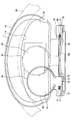
- the display device shown in FIG. 1 is assembled to a portion of the instrument panel (instrument panel) installed in the vehicle interior that is located on the front side of the driver's seat.
- instrument panel instrument panel
- FIG. 1 the illustration of the instrument panel is omitted, and a portion of the display device that is visually recognized in a state assembled to the instrument panel is illustrated.
- the display device includes a case 10, a dial 20 (display unit), a liquid crystal display unit 30 (display unit), a circuit board 40, a pointer 50, and a decoration ring 60 (decoration member). ) And the like.
- the case 10 is made of a resin having a light shielding property, and accommodates and holds the dial plate 20, the liquid crystal display unit 30, the circuit board 40, and the like.
- a facing plate 11 (upper facing plate) disposed on the upper side of the case 10 described later and a facing plate 12 (lower facing plate) disposed on the lower side of the case 10 are integrally formed of resin. Has been.
- the dial plate 20 is made of a resin having translucency, and has a scale display unit 21, a character display unit 22, and a bar display unit 23 that are transmitted and illuminated by the light source L1.
- these display units 21, 22, and 23 are collectively referred to as a dial display unit, and a portion of the dial plate 20 that forms the scale display unit 21, the character display unit 22, and the bar display unit 23.
- a display unit Each corresponds to a display unit.
- a portion where the dial plate display portion is formed and a portion facing the liquid crystal display unit 30 have translucency, and light shielding paint is printed on the other portions. Therefore, when the light source L1 is turned on, the dial plate display portion is transmitted and illuminated and is visually recognized. Further, by controlling the lighting range of the light source L1, the visible range of the bar display unit 23 is changed, thereby expressing a wattmeter that represents the remaining amount of power of the in-vehicle battery and a fuel meter that represents the remaining amount of fuel. .
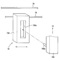
- the upper facing plate 11 and the lower facing plate 12 are arranged on the front side (left side in FIG. 2) in the visual recognition direction with respect to the dial plate 20.
- portions located inside the openings 11 a and 12 a of the facing plates 11 and 12 become a visible display area. That is, the facing plates 11 and 12 function as a display frame of the dial plate 20.
- the liquid crystal display unit 30 is configured to include a backlight and a liquid crystal panel, and is disposed on the back side in the viewing direction with respect to the dial plate 20.
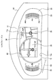
- the display surface 30a of the liquid crystal display unit 30 is located at the center of the display area of the dial plate 20, and the dial plate display portions are arranged on both the left and right sides of the display surface 30a. When the backlight is turned on, the image displayed on the display surface 30a is seen through the dial plate 20.
- a pointer image 31, a scale image 32, and a numeric image 33 are displayed on the display surface 30a, and a vehicle speedometer is represented by these images. That is, the pointer image 31 is rotated and displayed according to the vehicle speed, and the vehicle speed is represented by the scale image 32 pointed to by the pointer image 31.
- a vehicle speed image 34 that expresses the vehicle speed as a number
- a map image 35 that shows the current position of the host vehicle
- an enlarged map image 36 that guides and displays a planned left / right turn location in the map image 35. It is displayed on the display surface 30a.
- the enlarged map image 36 may be displayed at all times, or may be displayed in a pop-up during a period in which the distance between the current travel position of the host vehicle and the planned left / right turn is less than a predetermined value.
- the vehicle speed image 34, the oil temperature image 37 representing the hydraulic oil temperature, and the boost pressure image 38 representing the boost pressure of the internal combustion engine are displayed on the display surface 30a.
- Each part of the liquid crystal display unit 30 displaying these images corresponds to a display unit.
- these image display portions are collectively referred to as a liquid crystal display portion.
- the circuit board 40 is disposed on the far side in the viewing direction with respect to the liquid crystal display unit 30.
- a microcomputer microcomputer 41
- the microcomputer 41 includes a central processing unit, a memory, and the like, and controls various operations according to a program stored in advance, thereby controlling the operations of the light sources L1, L2 and the electric motors M1, M2, An image signal is output to the liquid crystal display unit 30.
- Rotating shaft 51 of electric motor M1 is attached to pointer 50.
- the pointer 50 is disposed on the near side in the visual recognition direction with respect to the dial plate 20, and when the electric motor M ⁇ b> 1 is driven, the pointer 50 rotates along the surface of the dial plate 20.
- the pointer 50 is made of a resin having translucency, and is illuminated by light emitted from the light source L2 and incident on the inside of the pointer 50, and is visually recognized as the pointer 50 is emitting light.
- the turning range of the pointer 50 includes a visual recognition area (see FIG. 6) that is visible inside the opening 12a of the lower facing plate 12 and a retreat that is invisible outside the opening 12a. A region (see FIGS. 1 and 5) is provided.
- the decorative ring 60 is made of a resin having a light shielding property and is painted in an arbitrary color.
- the display board 61 is made of a light-transmitting resin, and groove-shaped reflecting portions 61 a and 61 b are formed on the back surface of the display board 61.
- the light emitted from the light source L3 is incident and guided through the edge portion of the display plate 61, is reflected by the reflecting portions 61a and 61b, and is emitted from the surface of the display plate 61. Thereby, it visually recognizes that the reflection parts 61a and 61b are light-emitting.
- the reflecting portions 61a and 61b are formed in a shape representing a scale and a number indicated by the pointer 50.
- the light reflected from the outer peripheral edge of the display board 61 among the light incident from the edge part of the display board 61 is covered with the decoration ring 60 and is not visually recognized.
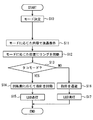
- step S13 it is determined whether or not the determined display mode is a mode for decorating the pointer 50 (octopus mode).
- the electric motor M1 is drive-controlled so that the pointer 50 is rotated to a position corresponding to the engine speed.
- step S15 the light source L2 is turned on to illuminate the pointer 50, and the light source L3 is turned on so that the scales and numbers by the reflecting portions 61a and 61b are visually recognized.
Landscapes
- Engineering & Computer Science (AREA)
- Chemical & Material Sciences (AREA)
- Physics & Mathematics (AREA)
- Combustion & Propulsion (AREA)
- Mechanical Engineering (AREA)
- Transportation (AREA)
- General Physics & Mathematics (AREA)
- Nonlinear Science (AREA)
- Crystallography & Structural Chemistry (AREA)
- Theoretical Computer Science (AREA)
- Computer Hardware Design (AREA)
- Optics & Photonics (AREA)
- Mathematical Physics (AREA)
- Instrument Panels (AREA)
- Indicating Measured Values (AREA)
Abstract
Description
以上、開示の好ましい実施形態について説明したが、開示は上述した実施形態に何ら制限されることなく、以下に例示するように種々変形して実施することが可能である。各実施形態で具体的に組合せが可能であることを明示している部分同士の組合せばかりではなく、特に組合せに支障が生じなければ、明示してなくとも実施形態同士を部分的に組み合せることも可能である。
Claims (5)
- 互いに異なる内容を表示する複数の表示部(31、32、33、34、35、36、37、38、50、61、21、22、23)と、
複数の前記表示部のいずれかを加飾する加飾部材(60)と、
前記加飾部材を移動させるアクチュエータ(M2)と、
複数の前記表示部のうち選択された表示部を加飾する位置へ前記加飾部材を移動させるよう、前記アクチュエータを制御する制御部(41)と、
を備える表示装置。 - ステアリングホイール(SH)の車両前方側に配置された表示装置において、
前記加飾部材は、前記ステアリングホイールの円弧に沿って移動可能に配置されている請求項1に記載の表示装置。 - 光源(L3)と、
前記光源の光を反射して所定の形状に視認させる反射部(61a、61b)を有するとともに、前記表示部に対して視認方向の手前側にて配置された、透光性を有する表示板(61)と、
前記光源の点灯に伴い視認される前記反射部を前記加飾部材に加飾させる反射部表示モードと、前記光源の消灯に伴い前記表示板を透かして視認される前記表示部を前記加飾部材に加飾させる反射部非表示モードとに切り替える光源制御部(S15、S17)と、をさらに備える請求項1または2に記載の表示装置。 - 前記アクチュエータは、前記加飾部材とともに前記表示板を移動させる請求項3に記載の表示装置。
- 前記加飾部材および前記表示部に対して視認方向の手前側に配置され、表示領域を規定する表示枠として機能する見返し板(12)をさらに備え、
前記加飾部材の移動に伴い、前記加飾部材のうち前記見返し板により隠れる部分の面積が変化する請求項1~4のいずれか1つに記載の表示装置。
Priority Applications (6)
| Application Number | Priority Date | Filing Date | Title |
|---|---|---|---|
| DE112015003326.2T DE112015003326T5 (de) | 2014-07-18 | 2015-06-25 | Anzeigevorrichtung |
| US15/323,451 US10040354B2 (en) | 2014-07-18 | 2015-06-25 | Display apparatus |
| KR1020177004177A KR101947927B1 (ko) | 2014-07-18 | 2015-06-25 | 표시 장치 |
| CN201580039598.8A CN106536255B (zh) | 2014-07-18 | 2015-06-25 | 显示装置 |
| KR1020187015900A KR101925265B1 (ko) | 2014-07-18 | 2015-06-25 | 표시 장치 |
| US15/953,542 US10761369B2 (en) | 2014-07-18 | 2018-04-16 | Display apparatus |
Applications Claiming Priority (2)
| Application Number | Priority Date | Filing Date | Title |
|---|---|---|---|
| JP2014147405A JP6274040B2 (ja) | 2014-07-18 | 2014-07-18 | 表示装置 |
| JP2014-147405 | 2014-07-18 |
Related Child Applications (2)
| Application Number | Title | Priority Date | Filing Date |
|---|---|---|---|
| US15/323,451 A-371-Of-International US10040354B2 (en) | 2014-07-18 | 2015-06-25 | Display apparatus |
| US15/953,542 Continuation US10761369B2 (en) | 2014-07-18 | 2018-04-16 | Display apparatus |
Publications (1)
| Publication Number | Publication Date |
|---|---|
| WO2016009598A1 true WO2016009598A1 (ja) | 2016-01-21 |
Family
ID=55078112
Family Applications (1)
| Application Number | Title | Priority Date | Filing Date |
|---|---|---|---|
| PCT/JP2015/003195 Ceased WO2016009598A1 (ja) | 2014-07-18 | 2015-06-25 | 表示装置 |
Country Status (6)
| Country | Link |
|---|---|
| US (2) | US10040354B2 (ja) |
| JP (1) | JP6274040B2 (ja) |
| KR (2) | KR101947927B1 (ja) |
| CN (2) | CN106536255B (ja) |
| DE (1) | DE112015003326T5 (ja) |
| WO (1) | WO2016009598A1 (ja) |
Cited By (2)
| Publication number | Priority date | Publication date | Assignee | Title |
|---|---|---|---|---|
| US20190071008A1 (en) * | 2017-09-01 | 2019-03-07 | Yazaki Corporation | Vehicle display device |
| US10259385B2 (en) | 2017-05-25 | 2019-04-16 | Denso Corporation | Vehicular display device |
Families Citing this family (11)
| Publication number | Priority date | Publication date | Assignee | Title |
|---|---|---|---|---|
| JP6274040B2 (ja) * | 2014-07-18 | 2018-02-07 | 株式会社デンソー | 表示装置 |
| EP3040829A1 (de) * | 2015-01-02 | 2016-07-06 | Volkswagen AG | Anwenderschnittstelle und Verfahren zum Betrieb einer Anwenderschnittstelle für ein Fortbewegungsmittel |
| JP6467386B2 (ja) * | 2016-09-14 | 2019-02-13 | 矢崎総業株式会社 | 車両用表示装置 |
| CN109964101B (zh) * | 2016-11-08 | 2021-10-29 | 株式会社电装 | 车辆用显示装置 |
| JP6876493B2 (ja) * | 2017-04-07 | 2021-05-26 | 矢崎総業株式会社 | 車両用表示装置 |
| JP6760903B2 (ja) * | 2017-09-01 | 2020-09-23 | 矢崎総業株式会社 | 車両用表示装置 |
| JP7134895B2 (ja) | 2019-02-13 | 2022-09-12 | 本田技研工業株式会社 | 表示装置 |
| US11001146B2 (en) * | 2019-04-05 | 2021-05-11 | Caterpillar Paving Products Inc. | Machine console system |
| US11667195B2 (en) | 2019-12-13 | 2023-06-06 | Honda Motor Co., Ltd. | Display system for a vehicle |
| US11364804B2 (en) | 2019-12-13 | 2022-06-21 | Honda Motor Co., Ltd. | Display system for mode information display |
| CN117221481A (zh) * | 2023-10-08 | 2023-12-12 | 黄弟 | 一种数字化会议系统 |
Citations (9)
| Publication number | Priority date | Publication date | Assignee | Title |
|---|---|---|---|---|
| DE4240465A1 (de) * | 1992-12-02 | 1994-06-09 | Vdo Schindling | Kombinationsinstrument |
| DE19744382A1 (de) * | 1996-10-09 | 1998-04-30 | Volkswagen Ag | Multifunktionsanzeige für Kraftfahrzeuge |
| DE10331131A1 (de) * | 2003-07-09 | 2005-01-27 | Borg Instruments Ag | Kombiinstrument |
| DE102004024596A1 (de) * | 2003-09-09 | 2005-03-31 | Volkswagen Ag | Displayanordnung für ein Fahrzeug |
| JP2005331317A (ja) * | 2004-05-19 | 2005-12-02 | Yazaki Corp | 複合型表示装置 |
| JP2006021575A (ja) * | 2004-07-06 | 2006-01-26 | Denso Corp | 車両用表示装置 |
| JP2008030638A (ja) * | 2006-07-28 | 2008-02-14 | Denso Corp | 車載用メーター表示装置 |
| JP2010175411A (ja) * | 2009-01-30 | 2010-08-12 | Nippon Seiki Co Ltd | 指示計器装置 |
| JP4637546B2 (ja) * | 2004-11-02 | 2011-02-23 | 矢崎総業株式会社 | 車両用表示装置 |
Family Cites Families (36)
| Publication number | Priority date | Publication date | Assignee | Title |
|---|---|---|---|---|
| KR970009793B1 (ko) * | 1991-08-19 | 1997-06-18 | 미쯔비시 지도샤 고교 가부시끼가이샤 | 차량용 표시 장치 |
| JPH08175225A (ja) * | 1994-12-27 | 1996-07-09 | Mitsubishi Motors Corp | 車両用表示装置 |
| DE60044322D1 (de) | 1999-01-25 | 2010-06-17 | Nippon Seiki Co Ltd | Anzeige |
| JP3858498B2 (ja) * | 1999-01-29 | 2006-12-13 | 日本精機株式会社 | 表示装置 |
| US6542146B1 (en) * | 1999-05-27 | 2003-04-01 | Lear Corporation | Transparent electroluminescent display with mechanical gauge |
| JP3966122B2 (ja) | 2001-09-25 | 2007-08-29 | 株式会社デンソー | 車両用指針計器 |
| JP2004106662A (ja) * | 2002-09-17 | 2004-04-08 | Denso Corp | 車両用表示装置 |
| JP2004226247A (ja) | 2003-01-23 | 2004-08-12 | Calsonic Kansei Corp | 計器装置 |
| JP2005239042A (ja) * | 2004-02-27 | 2005-09-08 | Nippon Seiki Co Ltd | 車両用情報表示装置及び車両用情報表示方法 |
| FR2893553B1 (fr) * | 2005-11-18 | 2009-07-03 | Peugeot Citroen Automobiles Sa | Dispositif d'affichage escamotable pour un vehicule automobile et vehicule comportant un tel dispositif |
| JP4333697B2 (ja) * | 2006-06-06 | 2009-09-16 | トヨタ自動車株式会社 | 車両用表示装置 |
| JP4787102B2 (ja) | 2006-07-28 | 2011-10-05 | 矢崎総業株式会社 | 車両用表示装置 |
| US7874689B2 (en) | 2006-10-03 | 2011-01-25 | Denso Corporation | Display device |
| JP4853212B2 (ja) | 2006-10-03 | 2012-01-11 | 株式会社デンソー | 表示装置 |
| JP5082911B2 (ja) | 2008-02-15 | 2012-11-28 | 株式会社デンソー | 表示装置 |
| JP5173866B2 (ja) * | 2009-01-21 | 2013-04-03 | シャープ株式会社 | 項目選択装置と加熱調理器 |
| JP5180150B2 (ja) | 2009-06-04 | 2013-04-10 | 矢崎総業株式会社 | 表示装置 |
| CN102460079B (zh) | 2009-06-22 | 2015-06-17 | 日本精机株式会社 | 仪表装置 |
| JP2011015182A (ja) * | 2009-07-02 | 2011-01-20 | Funai Electric Co Ltd | 携帯端末 |
| DE102009048834A1 (de) * | 2009-10-09 | 2011-04-14 | Volkswagen Ag | Verfahren und Anzeigeeinrichtung zum Anzeigen von Informationen |
| WO2012102231A1 (ja) * | 2011-01-26 | 2012-08-02 | 矢崎総業株式会社 | 指針部材、指針ユニット、及び、指針計器 |
| US8878660B2 (en) * | 2011-06-28 | 2014-11-04 | Nissan North America, Inc. | Vehicle meter cluster |
| JP5720494B2 (ja) * | 2011-08-23 | 2015-05-20 | 日本精機株式会社 | 表示装置 |
| JP5835559B2 (ja) * | 2011-08-24 | 2015-12-24 | 日本精機株式会社 | 指針式表示装置 |
| JP5919724B2 (ja) | 2011-10-20 | 2016-05-18 | 日本精機株式会社 | 車両用ヘッドアップディスプレイ装置 |
| JP5823849B2 (ja) * | 2011-12-20 | 2015-11-25 | 川崎重工業株式会社 | 乗物用メータ表示装置及びその表示方法 |
| DE102011121758B4 (de) * | 2011-12-21 | 2023-01-05 | Volkswagen Aktiengesellschaft | Verfahren zur Ansteuerung einer Eingabe- und Anzeigevorrichtung, insbesondere eines Kraftfahrzeugs |
| DE102012200154B4 (de) * | 2012-01-05 | 2023-04-20 | Continental Automotive Technologies GmbH | Anzeigegerät für ein Kraftfahrzeug |
| JP5959208B2 (ja) * | 2012-01-20 | 2016-08-02 | アルパイン株式会社 | 車両用表示装置 |
| JP2013156219A (ja) * | 2012-01-31 | 2013-08-15 | Nippon Seiki Co Ltd | 計器装置 |
| JP5990399B2 (ja) * | 2012-05-09 | 2016-09-14 | 矢崎総業株式会社 | 車両用表示装置 |
| JP5971700B2 (ja) | 2012-05-17 | 2016-08-17 | アルパイン株式会社 | 表示装置 |
| JP6080681B2 (ja) * | 2012-09-04 | 2017-02-15 | アルパイン株式会社 | 車載用ディスプレイ装置 |
| JP2014115223A (ja) * | 2012-12-11 | 2014-06-26 | Alpine Electronics Inc | 車載用ディスプレイ装置 |
| JP6274040B2 (ja) * | 2014-07-18 | 2018-02-07 | 株式会社デンソー | 表示装置 |
| DE112015004066T5 (de) * | 2014-09-05 | 2017-05-11 | Denso Corporation | Anzeigevorrichtung |
-
2014
- 2014-07-18 JP JP2014147405A patent/JP6274040B2/ja not_active Expired - Fee Related
-
2015
- 2015-06-25 CN CN201580039598.8A patent/CN106536255B/zh not_active Expired - Fee Related
- 2015-06-25 CN CN201810953306.7A patent/CN109263474A/zh active Pending
- 2015-06-25 KR KR1020177004177A patent/KR101947927B1/ko not_active Expired - Fee Related
- 2015-06-25 KR KR1020187015900A patent/KR101925265B1/ko not_active Expired - Fee Related
- 2015-06-25 WO PCT/JP2015/003195 patent/WO2016009598A1/ja not_active Ceased
- 2015-06-25 DE DE112015003326.2T patent/DE112015003326T5/de not_active Withdrawn
- 2015-06-25 US US15/323,451 patent/US10040354B2/en active Active
-
2018
- 2018-04-16 US US15/953,542 patent/US10761369B2/en active Active
Patent Citations (9)
| Publication number | Priority date | Publication date | Assignee | Title |
|---|---|---|---|---|
| DE4240465A1 (de) * | 1992-12-02 | 1994-06-09 | Vdo Schindling | Kombinationsinstrument |
| DE19744382A1 (de) * | 1996-10-09 | 1998-04-30 | Volkswagen Ag | Multifunktionsanzeige für Kraftfahrzeuge |
| DE10331131A1 (de) * | 2003-07-09 | 2005-01-27 | Borg Instruments Ag | Kombiinstrument |
| DE102004024596A1 (de) * | 2003-09-09 | 2005-03-31 | Volkswagen Ag | Displayanordnung für ein Fahrzeug |
| JP2005331317A (ja) * | 2004-05-19 | 2005-12-02 | Yazaki Corp | 複合型表示装置 |
| JP2006021575A (ja) * | 2004-07-06 | 2006-01-26 | Denso Corp | 車両用表示装置 |
| JP4637546B2 (ja) * | 2004-11-02 | 2011-02-23 | 矢崎総業株式会社 | 車両用表示装置 |
| JP2008030638A (ja) * | 2006-07-28 | 2008-02-14 | Denso Corp | 車載用メーター表示装置 |
| JP2010175411A (ja) * | 2009-01-30 | 2010-08-12 | Nippon Seiki Co Ltd | 指示計器装置 |
Cited By (3)
| Publication number | Priority date | Publication date | Assignee | Title |
|---|---|---|---|---|
| US10259385B2 (en) | 2017-05-25 | 2019-04-16 | Denso Corporation | Vehicular display device |
| US20190071008A1 (en) * | 2017-09-01 | 2019-03-07 | Yazaki Corporation | Vehicle display device |
| US10464477B2 (en) * | 2017-09-01 | 2019-11-05 | Yazaki Corporation | Vehicle display device |
Also Published As
| Publication number | Publication date |
|---|---|
| KR101925265B1 (ko) | 2018-12-04 |
| US10761369B2 (en) | 2020-09-01 |
| DE112015003326T5 (de) | 2017-04-13 |
| KR20170030634A (ko) | 2017-03-17 |
| US20180229605A1 (en) | 2018-08-16 |
| US10040354B2 (en) | 2018-08-07 |
| US20170144544A1 (en) | 2017-05-25 |
| JP2016022810A (ja) | 2016-02-08 |
| JP6274040B2 (ja) | 2018-02-07 |
| CN106536255A (zh) | 2017-03-22 |
| CN106536255B (zh) | 2018-10-26 |
| CN109263474A (zh) | 2019-01-25 |
| KR20180064574A (ko) | 2018-06-14 |
| KR101947927B1 (ko) | 2019-02-13 |
Similar Documents
| Publication | Publication Date | Title |
|---|---|---|
| JP6274040B2 (ja) | 表示装置 | |
| KR101919218B1 (ko) | 차량용 표시 장치 | |
| KR101939506B1 (ko) | 표시 장치 | |
| WO2014199629A1 (ja) | 車両用表示装置 | |
| JP6760903B2 (ja) | 車両用表示装置 | |
| JP2016022743A (ja) | 車両用表示装置 | |
| JP2005257333A (ja) | 車両用表示装置 | |
| JP6455393B2 (ja) | 表示装置 | |
| WO2016035304A1 (ja) | 表示装置 | |
| CN108621795B (zh) | 车用显示装置 | |
| JP6264360B2 (ja) | 表示装置 | |
| JP5045403B2 (ja) | 指針計器 | |
| CN109421537B (zh) | 车用显示装置 | |
| JP2007085858A (ja) | 車両用指針計器 | |
| JP6400185B2 (ja) | 車両用表示装置 | |
| JP4933069B2 (ja) | 車両用指針計器 | |
| JP6512437B2 (ja) | 表示装置 | |
| JP2015147518A (ja) | 車両用表示装置 | |
| JP6477046B2 (ja) | 表示装置 | |
| JP2018069999A (ja) | 表示装置 | |
| JP2016033466A (ja) | 表示装置 |
Legal Events
| Date | Code | Title | Description |
|---|---|---|---|
| 121 | Ep: the epo has been informed by wipo that ep was designated in this application |
Ref document number: 15821822 Country of ref document: EP Kind code of ref document: A1 |
|
| WWE | Wipo information: entry into national phase |
Ref document number: 15323451 Country of ref document: US |
|
| WWE | Wipo information: entry into national phase |
Ref document number: 112015003326 Country of ref document: DE |
|
| ENP | Entry into the national phase |
Ref document number: 20177004177 Country of ref document: KR Kind code of ref document: A |
|
| 122 | Ep: pct application non-entry in european phase |
Ref document number: 15821822 Country of ref document: EP Kind code of ref document: A1 |