WO2016006718A1 - ハイブリッド作業車両 - Google Patents
ハイブリッド作業車両 Download PDFInfo
- Publication number
- WO2016006718A1 WO2016006718A1 PCT/JP2015/073678 JP2015073678W WO2016006718A1 WO 2016006718 A1 WO2016006718 A1 WO 2016006718A1 JP 2015073678 W JP2015073678 W JP 2015073678W WO 2016006718 A1 WO2016006718 A1 WO 2016006718A1
- Authority
- WO
- WIPO (PCT)
- Prior art keywords
- cooling device
- cooling
- disposed
- work vehicle
- electric
- Prior art date
- Legal status (The legal status is an assumption and is not a legal conclusion. Google has not performed a legal analysis and makes no representation as to the accuracy of the status listed.)
- Ceased
Links
Images



Classifications
-
- E—FIXED CONSTRUCTIONS
- E02—HYDRAULIC ENGINEERING; FOUNDATIONS; SOIL SHIFTING
- E02F—DREDGING; SOIL-SHIFTING
- E02F9/00—Component parts of dredgers or soil-shifting machines, not restricted to one of the kinds covered by groups E02F3/00 - E02F7/00
- E02F9/08—Superstructures; Supports for superstructures
- E02F9/0858—Arrangement of component parts installed on superstructures not otherwise provided for, e.g. electric components, fenders, air-conditioning units
- E02F9/0866—Engine compartment, e.g. heat exchangers, exhaust filters, cooling devices, silencers, mufflers, position of hydraulic pumps in the engine compartment
-
- B—PERFORMING OPERATIONS; TRANSPORTING
- B60—VEHICLES IN GENERAL
- B60K—ARRANGEMENT OR MOUNTING OF PROPULSION UNITS OR OF TRANSMISSIONS IN VEHICLES; ARRANGEMENT OR MOUNTING OF PLURAL DIVERSE PRIME-MOVERS IN VEHICLES; AUXILIARY DRIVES FOR VEHICLES; INSTRUMENTATION OR DASHBOARDS FOR VEHICLES; ARRANGEMENTS IN CONNECTION WITH COOLING, AIR INTAKE, GAS EXHAUST OR FUEL SUPPLY OF PROPULSION UNITS IN VEHICLES
- B60K1/00—Arrangement or mounting of electrical propulsion units
-
- B—PERFORMING OPERATIONS; TRANSPORTING
- B60—VEHICLES IN GENERAL
- B60K—ARRANGEMENT OR MOUNTING OF PROPULSION UNITS OR OF TRANSMISSIONS IN VEHICLES; ARRANGEMENT OR MOUNTING OF PLURAL DIVERSE PRIME-MOVERS IN VEHICLES; AUXILIARY DRIVES FOR VEHICLES; INSTRUMENTATION OR DASHBOARDS FOR VEHICLES; ARRANGEMENTS IN CONNECTION WITH COOLING, AIR INTAKE, GAS EXHAUST OR FUEL SUPPLY OF PROPULSION UNITS IN VEHICLES
- B60K11/00—Arrangement in connection with cooling of propulsion units
- B60K11/02—Arrangement in connection with cooling of propulsion units with liquid cooling
- B60K11/04—Arrangement or mounting of radiators, radiator shutters, or radiator blinds
-
- E—FIXED CONSTRUCTIONS
- E02—HYDRAULIC ENGINEERING; FOUNDATIONS; SOIL SHIFTING
- E02F—DREDGING; SOIL-SHIFTING
- E02F9/00—Component parts of dredgers or soil-shifting machines, not restricted to one of the kinds covered by groups E02F3/00 - E02F7/00
- E02F9/08—Superstructures; Supports for superstructures
- E02F9/0858—Arrangement of component parts installed on superstructures not otherwise provided for, e.g. electric components, fenders, air-conditioning units
-
- E—FIXED CONSTRUCTIONS
- E02—HYDRAULIC ENGINEERING; FOUNDATIONS; SOIL SHIFTING
- E02F—DREDGING; SOIL-SHIFTING
- E02F9/00—Component parts of dredgers or soil-shifting machines, not restricted to one of the kinds covered by groups E02F3/00 - E02F7/00
- E02F9/08—Superstructures; Supports for superstructures
- E02F9/0858—Arrangement of component parts installed on superstructures not otherwise provided for, e.g. electric components, fenders, air-conditioning units
- E02F9/0883—Tanks, e.g. oil tank, urea tank, fuel tank
-
- E—FIXED CONSTRUCTIONS
- E02—HYDRAULIC ENGINEERING; FOUNDATIONS; SOIL SHIFTING
- E02F—DREDGING; SOIL-SHIFTING
- E02F9/00—Component parts of dredgers or soil-shifting machines, not restricted to one of the kinds covered by groups E02F3/00 - E02F7/00
- E02F9/20—Drives; Control devices
- E02F9/2058—Electric or electro-mechanical or mechanical control devices of vehicle sub-units
- E02F9/2062—Control of propulsion units
- E02F9/2075—Control of propulsion units of the hybrid type
-
- B—PERFORMING OPERATIONS; TRANSPORTING
- B60—VEHICLES IN GENERAL
- B60K—ARRANGEMENT OR MOUNTING OF PROPULSION UNITS OR OF TRANSMISSIONS IN VEHICLES; ARRANGEMENT OR MOUNTING OF PLURAL DIVERSE PRIME-MOVERS IN VEHICLES; AUXILIARY DRIVES FOR VEHICLES; INSTRUMENTATION OR DASHBOARDS FOR VEHICLES; ARRANGEMENTS IN CONNECTION WITH COOLING, AIR INTAKE, GAS EXHAUST OR FUEL SUPPLY OF PROPULSION UNITS IN VEHICLES
- B60K11/00—Arrangement in connection with cooling of propulsion units
- B60K11/02—Arrangement in connection with cooling of propulsion units with liquid cooling
-
- B—PERFORMING OPERATIONS; TRANSPORTING
- B60—VEHICLES IN GENERAL
- B60K—ARRANGEMENT OR MOUNTING OF PROPULSION UNITS OR OF TRANSMISSIONS IN VEHICLES; ARRANGEMENT OR MOUNTING OF PLURAL DIVERSE PRIME-MOVERS IN VEHICLES; AUXILIARY DRIVES FOR VEHICLES; INSTRUMENTATION OR DASHBOARDS FOR VEHICLES; ARRANGEMENTS IN CONNECTION WITH COOLING, AIR INTAKE, GAS EXHAUST OR FUEL SUPPLY OF PROPULSION UNITS IN VEHICLES
- B60K1/00—Arrangement or mounting of electrical propulsion units
- B60K2001/003—Arrangement or mounting of electrical propulsion units with means for cooling the electrical propulsion units
- B60K2001/006—Arrangement or mounting of electrical propulsion units with means for cooling the electrical propulsion units the electric motors
-
- B—PERFORMING OPERATIONS; TRANSPORTING
- B60—VEHICLES IN GENERAL
- B60L—PROPULSION OF ELECTRICALLY-PROPELLED VEHICLES; SUPPLYING ELECTRIC POWER FOR AUXILIARY EQUIPMENT OF ELECTRICALLY-PROPELLED VEHICLES; ELECTRODYNAMIC BRAKE SYSTEMS FOR VEHICLES IN GENERAL; MAGNETIC SUSPENSION OR LEVITATION FOR VEHICLES; MONITORING OPERATING VARIABLES OF ELECTRICALLY-PROPELLED VEHICLES; ELECTRIC SAFETY DEVICES FOR ELECTRICALLY-PROPELLED VEHICLES
- B60L2210/00—Converter types
- B60L2210/40—DC to AC converters
-
- B—PERFORMING OPERATIONS; TRANSPORTING
- B60—VEHICLES IN GENERAL
- B60Y—INDEXING SCHEME RELATING TO ASPECTS CROSS-CUTTING VEHICLE TECHNOLOGY
- B60Y2200/00—Type of vehicle
- B60Y2200/40—Special vehicles
- B60Y2200/41—Construction vehicles, e.g. graders, excavators
- B60Y2200/412—Excavators
-
- B—PERFORMING OPERATIONS; TRANSPORTING
- B60—VEHICLES IN GENERAL
- B60Y—INDEXING SCHEME RELATING TO ASPECTS CROSS-CUTTING VEHICLE TECHNOLOGY
- B60Y2200/00—Type of vehicle
- B60Y2200/90—Vehicles comprising electric prime movers
- B60Y2200/92—Hybrid vehicles
-
- E—FIXED CONSTRUCTIONS
- E02—HYDRAULIC ENGINEERING; FOUNDATIONS; SOIL SHIFTING
- E02F—DREDGING; SOIL-SHIFTING
- E02F3/00—Dredgers; Soil-shifting machines
- E02F3/04—Dredgers; Soil-shifting machines mechanically-driven
- E02F3/28—Dredgers; Soil-shifting machines mechanically-driven with digging tools mounted on a dipper- or bucket-arm, i.e. there is either one arm or a pair of arms, e.g. dippers, buckets
- E02F3/30—Dredgers; Soil-shifting machines mechanically-driven with digging tools mounted on a dipper- or bucket-arm, i.e. there is either one arm or a pair of arms, e.g. dippers, buckets with a dipper-arm pivoted on a cantilever beam, i.e. boom
- E02F3/32—Dredgers; Soil-shifting machines mechanically-driven with digging tools mounted on a dipper- or bucket-arm, i.e. there is either one arm or a pair of arms, e.g. dippers, buckets with a dipper-arm pivoted on a cantilever beam, i.e. boom working downwardly and towards the machine, e.g. with backhoes
-
- Y—GENERAL TAGGING OF NEW TECHNOLOGICAL DEVELOPMENTS; GENERAL TAGGING OF CROSS-SECTIONAL TECHNOLOGIES SPANNING OVER SEVERAL SECTIONS OF THE IPC; TECHNICAL SUBJECTS COVERED BY FORMER USPC CROSS-REFERENCE ART COLLECTIONS [XRACs] AND DIGESTS
- Y10—TECHNICAL SUBJECTS COVERED BY FORMER USPC
- Y10S—TECHNICAL SUBJECTS COVERED BY FORMER USPC CROSS-REFERENCE ART COLLECTIONS [XRACs] AND DIGESTS
- Y10S903/00—Hybrid electric vehicles, HEVS
- Y10S903/902—Prime movers comprising electrical and internal combustion motors
- Y10S903/903—Prime movers comprising electrical and internal combustion motors having energy storing means, e.g. battery, capacitor
Definitions
- the present invention relates to a hybrid work vehicle.
- hybrid work vehicles have been proposed that travel by driving force from an engine and driving force from an electric motor.
- the hybrid work vehicle includes a radiator for cooling an electric device such as an inverter (hereinafter referred to as an “electric device radiator”).
- FIG. 8 is a schematic plan view showing the arrangement of a conventional electric radiator and the like. As shown in FIG. 8, in a conventional hybrid work vehicle, an engine radiator 132, an oil cooler 133, and an aftercooler 134 are arranged in a horizontal row, and an electric equipment radiator 131 is arranged on the front side thereof.
- An object of the present invention is to improve the cooling efficiency of refrigerant in an electric equipment radiator.
- the hybrid work vehicle includes an electric motor, an electric device, a fan, a partition member, and a cooling unit.
- the electric device is electrically connected to the electric motor.
- the fan generates cooling air.
- a partition member forms the ventilation path which guides cooling air.
- the cooling unit has a first cooling device and a second cooling device.
- the first cooling device cools a refrigerant that cools at least one of the electric motor and the electric device.
- the second cooling device is disposed on the side of the first cooling device.
- the cooling unit is arranged so as to block the ventilation path.
- the conventional electric equipment radiator 131 has been arranged independently on the upstream side of the cooling air with respect to the other radiators.
- the electric appliance radiator 131 is arranged in this way, the outside air passes through a region where the electric appliance radiator 131 is not arranged so as to avoid the electric appliance radiator 131 as indicated by an arrow A in FIG.
- the present inventors have found that it flows downstream of 131.
- the 1st cooling device which concerns on this invention is arrange
- the ventilation path may not be completely blocked by the cooling unit.
- the hybrid work vehicle further includes a third cooling device.
- the third cooling device is disposed on the downstream side of the cooling air with respect to the first cooling device.
- the first cooling device has a first inlet and a first outlet
- the third cooling device has a second inlet and a second outlet.
- the first inlet is disposed at one of the upper part and the lower part of the first cooling device and faces the upstream side of the cooling air.
- the first outlet is disposed on the other of the upper part and the lower part of the first cooling device and faces the upstream side of the cooling air.
- the second inlet is disposed at one of the upper part and the lower part of the third cooling device and faces the downstream side of the cooling air.
- the second outlet is disposed on the other of the upper part and the lower part of the third cooling device and faces the downstream side of the cooling air.
- the electric device is disposed upstream of the cooling air with respect to the cooling unit.
- the electric device includes a battery that stores electric power generated by the electric motor, and an inverter that converts electric power from direct current to alternating current.
- the long side of the inverter is shorter than the long side of the battery.
- the inverter is arranged close to the first cooling device in the long side direction of the inverter. According to this configuration, it is possible to suppress the cooling air from being blocked by the inverter and to sufficiently send the outside air to the first cooling device.
- the hybrid work vehicle further includes a hydraulic oil tank that stores hydraulic oil.
- the third cooling device is an oil cooler that cools the hydraulic oil.
- the third cooling device has a first surface facing the first cooling device and a second surface facing away from the first surface.
- the hydraulic oil tank is disposed on the side facing the second surface. According to this configuration, the pipe connecting the hydraulic oil tank and the third cooling device can be efficiently installed.
- the hybrid work vehicle further includes a control valve for controlling the flow rate of the hydraulic oil.
- the control valve is disposed on the side facing the second surface. According to this configuration, the piping connecting the control valve and the third cooling device can be efficiently installed.
- the cooling unit further includes a filling member disposed between the first cooling device and the second cooling device. According to this configuration, a sufficient amount of outside air can be sent by each cooling device.
- the cooling unit further includes a fourth cooling device disposed on a side of the second cooling device.
- the second cooling device is an engine radiator that cools the refrigerant for the engine.
- the hybrid work vehicle includes an electric motor, an electric device, a fan, a first cooling device, and a third cooling device.
- the electric device is electrically connected to the electric motor.
- the fan generates cooling air.
- the first cooling device cools at least one refrigerant of the electric motor and the electric device.
- the third cooling device is disposed on the downstream side of the cooling air with respect to the first cooling device.
- the first cooling device has a first inlet and a first outlet.
- the first inlet is disposed at one of the upper part and the lower part of the first cooling device and faces the upstream side of the cooling air.
- the first outlet is disposed on the other of the upper part and the lower part of the first cooling device and faces the upstream side of the cooling air.
- the third cooling device has a second inlet and a second outlet.
- the second inlet is disposed at one of the upper part and the lower part of the third cooling device and faces the downstream side of the cooling air.
- the second outlet is disposed on the other of the upper part and the lower part of the third cooling device and faces the downstream side of the cooling air.
- the cooling efficiency of the refrigerant in the electric equipment radiator can be improved.
- the perspective view of a hydraulic excavator The top view which shows an engine compartment.
- FIG. 1 is a perspective view of a hydraulic excavator 100.
- the excavator 100 includes a vehicle main body 101 and a work implement 10.
- the excavator 100 performs a desired work using the work machine 10.
- the hydraulic excavator 100 is a hybrid hydraulic excavator, and includes an engine 4, a generator motor 5, a swing motor 6, and the like as will be described later (see FIG. 7).
- energy generated when the vehicle body turns is decelerated is converted into electric energy by the turning electric motor and stored in the battery 71.
- the stored electric energy is used as auxiliary energy during engine acceleration through the generator motor 5.
- the turning electric motor 6 corresponds to the electric motor of the present invention.
- the vehicle body 101 includes a traveling body 102 and a turning body 103.
- the traveling body 102 includes a pair of traveling devices 104 and 105.
- the traveling device 104 has a crawler belt 106, and the traveling device 105 has a crawler belt 107.
- the traveling devices 104 and 105 cause the excavator 100 to travel by obtaining driving force from the engine 4 and the generator motor 5 described later to drive the crawler belts 106 and 107.
- the turning body 103 is placed on the traveling body 102 and is provided so as to be able to turn with respect to the traveling body 102.
- the turning body 103 turns in an arbitrary direction by the turning electric motor 6.
- the swing body 103 includes a cab 108, a fuel tank 109, a hydraulic oil tank 110, and an engine chamber 111.
- the fuel tank 109 stores fuel for driving the engine 4.
- the fuel tank 109 is disposed in front of the hydraulic oil tank 110.
- the hydraulic oil tank 110 stores hydraulic oil.
- the hydraulic oil tank 110 is arranged side by side with the fuel tank 109 in the front-rear direction. In the vehicle width direction, the fuel tank 109 and the hydraulic oil tank 110 are disposed at one end, and the cab 108 is disposed at the other end. In the present embodiment, the fuel tank 109 and the hydraulic oil tank 110 are disposed at the right end in the vehicle width direction, and the cab 108 is disposed at the left end.
- the engine chamber 111 is disposed behind the cab 108, the fuel tank 109, and the hydraulic oil tank 110.
- the engine chamber 111 is located at the rear part of the revolving structure 103.
- the engine chamber 111 extends in the vehicle width direction.
- the work machine 10 is attached to the front part of the revolving structure 103.
- the work machine 10 is driven by hydraulic oil.
- the work machine 10 includes a boom 11, an arm 12, a bucket 13, a boom cylinder 14, an arm cylinder 15, and a bucket cylinder 16.
- the working machine 10 according to the present embodiment includes a pair of boom cylinders 14.
- the base end portion of the boom 11 is rotatably connected to the swing body 103. Further, the base end portion of the arm 12 is rotatably connected to the tip end portion of the boom 11. Bucket 13 is rotatably connected to the tip of arm 12.
- Each boom cylinder 14, arm cylinder 15 and bucket cylinder 16 are hydraulic cylinders and are driven by hydraulic oil. Each cylinder 14 to 16 is driven by hydraulic oil discharged from a hydraulic pump (not shown). Each boom cylinder 14 operates the boom 11.
- the arm cylinder 15 operates the arm 12.
- the bucket cylinder 16 operates the bucket 13.
- the work machine 10 is driven by driving these cylinders 14-16.
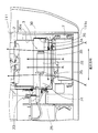
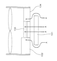
- FIG. 2 is a plan view showing the inside of the engine chamber 111.
- the cooling fan 2, the partition member 30, the cooling unit 3, the engine 4, the generator motor 5, the capacitor 71, the inverter 72, and the like are accommodated in the engine chamber 111.
- the engine chamber 111 is partitioned by a vehicle body cover 111a, an engine hood (not shown), a partition wall (not shown), and the like.
- the engine chamber 111 communicates with the outside through a vent hole (not shown) formed in the vehicle body cover 111a.
- the cooling fan 2 is configured to generate cooling air.
- the partition member 30 has an air passage 30a that guides cooling air.
- the partition member 30 has a plate shape and defines an air passage 30a.
- the cooling fan 2 is disposed at one end of the ventilation path 30a.
- the cooling air generated by the cooling fan 2 flows through the ventilation path 30a.
- the ventilation path 30a extends in the direction in which the cooling air flows.
- the cooling fan 2 sucks outside air into the engine chamber 111 from the outside of the engine chamber 111 by rotating.
- the cooling air generated by the cooling fan 2 is along the vehicle width direction. Further, the cooling air generated by the cooling fan 2 is rectified in the ventilation path 30a.
- the cooling unit 3 is arranged so as to block the ventilation path 30a.
- the cooling unit 3 is arrange
- the cooling unit 3 closes the ventilation path 30a at the other end of the ventilation path 30a.
- the cooling unit 3 includes a first cooling device 31, a second cooling device 32, a third cooling device 33, and a fourth cooling device 34.
- the cooling unit 3 further includes a filling member 35 for filling the gaps between the cooling devices.
- the filling member 35 is a sponge sheet, for example.
- the first cooling device 31 is an electric equipment radiator that cools the refrigerant for the battery 71 and the inverter 72. Note that the refrigerant cooled by the first cooling device 31 also cools the swing motor 6. Inside the first cooling device 31, a refrigerant for cooling the inverter 72 and the battery 71 flows.
- the 1st cooling device 31 is arrange
- the first cooling device 31 is disposed in front of the vehicle among the cooling units 3.
- a filling member 35 is disposed between the first cooling device 31 and the partition plate 30a.
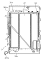
- FIG. 3 is a front view of the cooling unit 3 as viewed from the upstream side of the cooling air.
- the first cooling device 31 has a first inlet 31a and a first outlet 31b.
- the refrigerant is supplied into the first cooling device 31 through the first inlet 31a and discharged from the first cooling device 31 through the first outlet 31b.
- the first inlet 31a and the first outlet 31b face the upstream side of the cooling air.
- the first inlet 31 a is located at the upper end of the first cooling device 31, and the first outlet 31 b is located at the lower end of the first cooling device 31.
- a first supply pipe 301a is connected to the first inlet 31a, and a first discharge pipe 301b is connected to the first outlet 31b.
- the first supply pipe 301a and the first discharge pipe 301b connect an electric device 7 (to be described later) and the first cooling device 31.
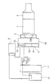
- FIG. 4 is a block diagram showing the flow of the refrigerant cooled by the first cooling device 31.
- the refrigerant cooled by the first cooling device 31 is supplied in this order to the capacitor 71, the inverter 72, and the swing motor 6, and cools the capacitor 71, the inverter 72, and the swing motor 6.
- the third cooling device 33 is disposed so as to face the first cooling device 31.
- the third cooling device 33 is disposed on the downstream side of the cooling air with respect to the first cooling device 31.
- the third cooling device 33 is, for example, an oil cooler that cools hydraulic oil.
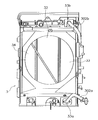
- FIG. 5 is a rear view of the cooling unit 3 as viewed from the downstream side of the cooling air.
- the 3rd cooling device 33 has the 2nd inlet 33a and the 2nd outlet 33b.
- hydraulic fluid is supplied in the 3rd cooling device 33 via the 2nd inlet 33a, and is discharged
- the second inlet 33a and the second outlet 33b face the downstream side of the cooling air.
- the second inlet 33 a is located at the lower end of the third cooling device 33, and the second outlet 33 b is located at the upper end of the third cooling device 33.
- a second supply pipe 302a is connected to the second inlet 33a, and a second discharge pipe 302b is connected to the second outlet 33b.
- the second supply pipe 302 a connects the third cooling device 33 and the control valve 112, and the second discharge pipe 302 b connects the third cooling device 33 and the hydraulic oil tank 110.
- the second cooling device 32 is disposed on the side of the first cooling device 31.
- the second cooling device 32 is disposed on the side of the first cooling device 31 in the orthogonal direction substantially orthogonal to the direction in which the ventilation path 30a extends.
- the orthogonal direction extends horizontally. In the present embodiment, the orthogonal direction is parallel to the vehicle longitudinal direction.
- the 1st cooling device 31 and the 2nd cooling device 32 are located in a line in the vehicle front-back direction.
- the second cooling device 32 is thicker than the first cooling device 31.
- the second cooling device 32 has a size larger than that of the first cooling device 31 in the direction in which the ventilation path 30 a extends.
- the second cooling device 32 is disposed on an extension line of the rotation axis of the cooling fan 2.
- the wind receiving surface of the first cooling device 31 and the wind receiving surface of the second cooling device 32 are disposed on substantially the same plane. Note that the air receiving surface of each cooling device is a surface facing the upstream side of the cooling air.
- the 2nd cooling device 32 is an engine radiator which cools the refrigerant for engines, for example.
- a filling member 35 is disposed between the second cooling device 32 and the first and third cooling devices 31 and 33.
- the fourth cooling device 34 is disposed on the side of the second cooling device 32.
- the fourth cooling device 34 is disposed on the side of the second cooling device 32 in the orthogonal direction. In the orthogonal direction, the first cooling device 31, the second cooling device 32, and the fourth cooling device 34 are arranged in this order.
- the wind receiving surface of the fourth cooling device 31 is disposed on substantially the same plane as the wind receiving surfaces of the first and second cooling devices 31 and 32.
- the fourth cooling device 34 is, for example, an aftercooler for cooling the compressed supercharged air.
- a filling member 35 is disposed between the fourth cooling device 34 and the second cooling device 32.
- a filling member 35 is also disposed between the fourth cooling device 34 and the partition plate 30a. As described above, the ventilation path 30 a is blocked by the first cooling device 31, the second cooling device 32, and the fourth cooling device 34. Further, the gap between the cooling devices is filled with the filling member 35. Note that the air passage 30a may not be completely blocked.
- the electrical equipment 7 is arranged on the upstream side of the cooling air of the cooling unit 3.
- the electric device 7 is cooled by the refrigerant from the first cooling device 31.
- the electric device 7 is electrically connected to the swing motor 6.
- FIG. 6 is a side view showing the inside of the engine chamber 111.
- the electric device 7 includes a capacitor 71 and an inverter 72.
- the battery 71 stores the electric power generated by the turning electric motor 6.
- the inverter 72 converts the electric power generated by the turning electric motor 6 from direct current to alternating current.
- the inverter 72 is arranged on the upper surface of the battery 71.
- the battery 71 and the inverter 72 extend along the direction in which the first cooling device 31 and the second cooling device 32 are arranged.
- the battery 71 and the inverter 72 extend in the orthogonal direction. In the present embodiment, the battery 71 and the inverter 72 extend in the front-rear direction.
- the long side of the inverter 72 is shorter than the long side of the battery 71. In the orthogonal direction, the inverter 72 is shorter than the battery 71.
- the inverter 72 is arranged in a direction away from the first cooling device 31 in the orthogonal direction.
- the capacitor 71 extends from the first cooling device 31 to the fourth cooling device 34 in the orthogonal direction.
- the inverter 72 extends from the second cooling device 32 to the fourth cooling device 34 in the orthogonal direction.
- the inverter 72 is arranged so as not to obstruct the flow of the cooling air flowing to the first cooling device 31.
- FIG. 7 is a plan view showing the arrangement of each member.
- the third cooling device 33 has a first surface 331 that faces the first cooling device 31, and a second surface 332 that faces away from the first surface 331.
- the first surface 331 faces the first side (left side) in the vehicle width direction
- the second surface 332 faces the second side (right side) in the vehicle width direction.
- the hydraulic oil tank 110 is disposed on the side where the second surface 332 faces.
- the control valve 112 is also arranged on the side where the second surface 332 faces. Note that the control valve 112 is configured to control the flow rate of hydraulic oil supplied to the hydraulic equipment.
- the electric device 7 is disposed on the side where the first surface 331 faces.
- the condenser 71 and the inverter 72 are arranged on the first side (left side) in the vehicle width direction with the cooling unit 3 as a reference, and the hydraulic oil tank 110 and the control valve 112 are arranged on the second side (right side) in the vehicle width direction. ing. In the vehicle width direction, the electric device 7, the cooling unit 3, the control valve 112, and the hydraulic oil tank 110 are arranged in this order.
- the hydraulic excavator 100 can improve the cooling efficiency of the refrigerant in the first cooling device 31 as compared with the conventional hydraulic excavator.
- the conventional electric equipment radiator 131 is arranged independently on the upstream side of the cooling air with respect to the other radiators. For this reason, as shown by the arrow A in FIG. 8, the outside air flows downstream of the electric equipment radiator 131 through a region where the electric equipment radiator 131 is not disposed so as to avoid the electric equipment radiator 131.
- the 1st cooling device 31 is arrange
- the outside air flows so as to pass through the cooling devices 31 to 34 of the cooling unit 3 as indicated by an arrow A in FIG. For this reason, the outside air sufficiently passes through the first cooling device 31 and the cooling efficiency of the refrigerant in the first cooling device 31 can be improved.
- the first cooling device 31 is not arranged on the upstream side of the cooling unit 3, and is arranged in the ventilation path 30 a as a part of the cooling unit 3. For this reason, the space of the upstream of the cooling unit 3 can be ensured, and maintenance of the cooling unit 3 etc. can be made easy by extension. Moreover, since the 1st cooling device 31 is not arrange
- the first cooling device 31 is not arranged alone but as a part of the cooling unit 3, the first cooling device 31 is supported by a support member that supports the other cooling devices 32-34. be able to. Unlike the prior art, there is no need to separately provide a support member for the first cooling device 31.
- the cooling unit 3 includes the first to fourth cooling devices 31 to 34, but is not particularly limited thereto.
- the cooling unit 3 may not include the fourth cooling device 34.
- the cooling unit 3 may further include another cooling device.
- the order of the cooling devices in the orthogonal direction is not particularly limited to the order of the above embodiment.
- the present invention is applied to a hydraulic excavator, but the present invention can also be applied to other hybrid work vehicles such as a wheel loader or a motor grader.
Landscapes
- Engineering & Computer Science (AREA)
- Mining & Mineral Resources (AREA)
- Civil Engineering (AREA)
- General Engineering & Computer Science (AREA)
- Structural Engineering (AREA)
- Mechanical Engineering (AREA)
- Combustion & Propulsion (AREA)
- Transportation (AREA)
- Chemical & Material Sciences (AREA)
- Cooling, Air Intake And Gas Exhaust, And Fuel Tank Arrangements In Propulsion Units (AREA)
- Hybrid Electric Vehicles (AREA)
- Operation Control Of Excavators (AREA)
- Component Parts Of Construction Machinery (AREA)
Abstract
Description
以上、本発明の実施形態について説明したが、本発明はこれらに限定されるものではなく、本発明の趣旨を逸脱しない限りにおいて種々の変更が可能である。
3 冷却ユニット
30 仕切部材
30a 通風路
31 第1冷却装置
32 第2冷却装置
33 第3冷却装置
6 旋回電動機
Claims (8)
- 電動機と、
前記電動機と電気的に接続される電気機器と、
冷却風を生成するファンと、
前記冷却風を導く通風路を形成する仕切部材と、
前記電動機及び前記電気機器の少なくとも一方を冷却する冷媒を冷却する第1冷却装置、及び前記第1冷却装置の側方に配置される第2冷却装置、を有し、前記通風路を塞ぐように配置される冷却ユニットと、
を備える、
ハイブリッド作業車両。 - 前記第1冷却装置に対して、前記冷却風の下流側に配置される第3冷却装置をさらに備え、
前記第1冷却装置は、当該第1冷却装置の上部及び下部の一方に配置され且つ前記冷却風の上流側を向く第1入口と、当該第1冷却装置の上部及び下部の他方に配置され且つ前記冷却風の上流側を向く第1出口と、を有し、
前記第3冷却装置は、当該第3冷却装置の上部及び下部の一方に配置され且つ前記冷却風の下流側を向く第2入口と、当該第3冷却装置の上部及び下部の他方に配置され且つ前記冷却風の下流側を向く第2出口と、を有する、
請求項1に記載のハイブリッド作業車両。 - 前記電気機器は、前記冷却ユニットに対して、前記冷却風の上流側に配置され、
前記電気機器は、前記電動機によって生成される電力を蓄電する蓄電器と、前記蓄電器の上面に配置され前記電力を直流から交流に変換するインバータと、を有し、
前記インバータの長辺は、前記蓄電器の長辺よりも短く、
前記インバータは、前記インバータの長辺方向において前記第1冷却装置から離れる方向に寄せられて配置される、
請求項1又は2に記載の作業車両。 - 作動油を貯留する作動油タンクをさらに備え、
前記第3冷却装置は、前記作動油を冷却するオイルクーラであり、
前記第3冷却装置は、前記第1冷却装置と対向する第1面と、前記第1面と反対を向く第2面とを有し、
前記作動油タンクは、前記第2面が向く側に配置される、
請求項1から3のいずれかに記載のハイブリッド作業車両。 - 前記第2面が向く側に配置され、前記作動油の流量を制御する制御バルブをさらに備える、
請求項4に記載のハイブリッド作業車両。 - 前記冷却ユニットは、前記第1冷却装置と前記第2冷却装置との間に配置される充填部材をさらに有する、
請求項1から5のいずれかに記載のハイブリッド作業車両。 - 前記冷却ユニットは、前記第2冷却装置の側方に配置される第4冷却装置をさらに有する、
請求項1から6のいずれかに記載のハイブリッド作業車両。 - 前記第2冷却装置は、前記エンジン用の冷媒を冷却するエンジンラジエータである、
請求項1から7のいずれかに記載のハイブリッド作業車両。
Priority Applications (6)
| Application Number | Priority Date | Filing Date | Title |
|---|---|---|---|
| PCT/JP2015/073678 WO2016006718A1 (ja) | 2015-08-24 | 2015-08-24 | ハイブリッド作業車両 |
| DE112015000111.5T DE112015000111T5 (de) | 2015-08-24 | 2015-08-24 | Hybridarbeitsfahrzeug |
| CN201580001100.9A CN105408156A (zh) | 2015-08-24 | 2015-08-24 | 混合动力作业车辆 |
| JP2016532996A JP6078696B2 (ja) | 2015-08-24 | 2015-08-24 | ハイブリッド作業車両 |
| KR1020157036085A KR20170023703A (ko) | 2015-08-24 | 2015-08-24 | 하이브리드 작업 차량 |
| US14/909,541 US20170058485A1 (en) | 2015-08-24 | 2015-08-24 | Hybrid work vehicle |
Applications Claiming Priority (1)
| Application Number | Priority Date | Filing Date | Title |
|---|---|---|---|
| PCT/JP2015/073678 WO2016006718A1 (ja) | 2015-08-24 | 2015-08-24 | ハイブリッド作業車両 |
Publications (1)
| Publication Number | Publication Date |
|---|---|
| WO2016006718A1 true WO2016006718A1 (ja) | 2016-01-14 |
Family
ID=55064339
Family Applications (1)
| Application Number | Title | Priority Date | Filing Date |
|---|---|---|---|
| PCT/JP2015/073678 Ceased WO2016006718A1 (ja) | 2015-08-24 | 2015-08-24 | ハイブリッド作業車両 |
Country Status (6)
| Country | Link |
|---|---|
| US (1) | US20170058485A1 (ja) |
| JP (1) | JP6078696B2 (ja) |
| KR (1) | KR20170023703A (ja) |
| CN (1) | CN105408156A (ja) |
| DE (1) | DE112015000111T5 (ja) |
| WO (1) | WO2016006718A1 (ja) |
Cited By (4)
| Publication number | Priority date | Publication date | Assignee | Title |
|---|---|---|---|---|
| WO2016104817A1 (ja) * | 2016-01-18 | 2016-06-30 | 株式会社小松製作所 | 冷却装置およびそれを備えた作業車両 |
| JP2017226283A (ja) * | 2016-06-21 | 2017-12-28 | 株式会社クボタ | 作業機 |
| JP2018119457A (ja) * | 2017-01-25 | 2018-08-02 | 株式会社竹内製作所 | 作業用車両 |
| JP2021021379A (ja) * | 2019-07-30 | 2021-02-18 | 本田技研工業株式会社 | 車体構造 |
Families Citing this family (5)
| Publication number | Priority date | Publication date | Assignee | Title |
|---|---|---|---|---|
| JP6040187B2 (ja) * | 2014-02-24 | 2016-12-07 | 日立建機株式会社 | 建設機械 |
| JP6356002B2 (ja) * | 2014-07-28 | 2018-07-11 | 日立建機株式会社 | ハイブリッド式作業機 |
| KR102373313B1 (ko) | 2018-07-12 | 2022-03-10 | 주식회사 엘지에너지솔루션 | 무기 전해액을 포함하는 리튬 이차전지 |
| US11821173B2 (en) | 2019-09-25 | 2023-11-21 | Caterpillar Inc. | Inverter location and orientation within a mobile machine |
| KR102857073B1 (ko) * | 2020-02-27 | 2025-09-08 | 얀마 파워 테크놀로지 가부시키가이샤 | 작업 차량의 냉각 장치 |
Citations (5)
| Publication number | Priority date | Publication date | Assignee | Title |
|---|---|---|---|---|
| JP2004169465A (ja) * | 2002-11-21 | 2004-06-17 | Komatsu Ltd | ハイブリッド式建設機械の機器配置構造 |
| JP2005307599A (ja) * | 2004-04-22 | 2005-11-04 | Hitachi Constr Mach Co Ltd | 建設機械の冷却装置配設構造 |
| JP2006205791A (ja) * | 2005-01-25 | 2006-08-10 | Toyota Motor Corp | ハイブリッド駆動装置の冷却装置 |
| JP2011190566A (ja) * | 2010-03-11 | 2011-09-29 | Komatsu Utility Co Ltd | エンジンルーム内の仕切構造 |
| JP2013002170A (ja) * | 2011-06-17 | 2013-01-07 | Komatsu Ltd | 油圧ショベル |
Family Cites Families (6)
| Publication number | Priority date | Publication date | Assignee | Title |
|---|---|---|---|---|
| JP3616005B2 (ja) * | 2000-12-20 | 2005-02-02 | 本田技研工業株式会社 | ハイブリッド車両の冷却装置 |
| JP4233529B2 (ja) * | 2005-01-21 | 2009-03-04 | カルソニックカンセイ株式会社 | 車両の冷却装置 |
| JP4981050B2 (ja) | 2006-08-02 | 2012-07-18 | 株式会社小松製作所 | ハイブリッド作業車両 |
| JP5379537B2 (ja) * | 2009-03-31 | 2013-12-25 | 本田技研工業株式会社 | 燃料電池車両用冷却装置 |
| US8781658B2 (en) * | 2010-10-28 | 2014-07-15 | GM Global Technology Operations LLC | Systems and methods for determining the target thermal conditioning value to control a rechargeable energy storage system |
| JP2015116877A (ja) * | 2013-12-17 | 2015-06-25 | トヨタ自動車株式会社 | 燃料電池車両 |
-
2015
- 2015-08-24 WO PCT/JP2015/073678 patent/WO2016006718A1/ja not_active Ceased
- 2015-08-24 DE DE112015000111.5T patent/DE112015000111T5/de not_active Withdrawn
- 2015-08-24 KR KR1020157036085A patent/KR20170023703A/ko not_active Ceased
- 2015-08-24 JP JP2016532996A patent/JP6078696B2/ja not_active Expired - Fee Related
- 2015-08-24 CN CN201580001100.9A patent/CN105408156A/zh active Pending
- 2015-08-24 US US14/909,541 patent/US20170058485A1/en not_active Abandoned
Patent Citations (5)
| Publication number | Priority date | Publication date | Assignee | Title |
|---|---|---|---|---|
| JP2004169465A (ja) * | 2002-11-21 | 2004-06-17 | Komatsu Ltd | ハイブリッド式建設機械の機器配置構造 |
| JP2005307599A (ja) * | 2004-04-22 | 2005-11-04 | Hitachi Constr Mach Co Ltd | 建設機械の冷却装置配設構造 |
| JP2006205791A (ja) * | 2005-01-25 | 2006-08-10 | Toyota Motor Corp | ハイブリッド駆動装置の冷却装置 |
| JP2011190566A (ja) * | 2010-03-11 | 2011-09-29 | Komatsu Utility Co Ltd | エンジンルーム内の仕切構造 |
| JP2013002170A (ja) * | 2011-06-17 | 2013-01-07 | Komatsu Ltd | 油圧ショベル |
Cited By (9)
| Publication number | Priority date | Publication date | Assignee | Title |
|---|---|---|---|---|
| WO2016104817A1 (ja) * | 2016-01-18 | 2016-06-30 | 株式会社小松製作所 | 冷却装置およびそれを備えた作業車両 |
| CN105874180A (zh) * | 2016-01-18 | 2016-08-17 | 株式会社小松制作所 | 冷却装置及具备其的作业车辆 |
| JPWO2016104817A1 (ja) * | 2016-01-18 | 2017-04-27 | 株式会社小松製作所 | 冷却装置およびそれを備えた作業車両 |
| US9802472B2 (en) | 2016-01-18 | 2017-10-31 | Komatsu Ltd. | Cooling device and work vehicle equipped with same |
| KR101808630B1 (ko) * | 2016-01-18 | 2017-12-13 | 가부시키가이샤 고마쓰 세이사쿠쇼 | 냉각 장치 및 냉각 장치를 구비한 작업 차량 |
| JP2017226283A (ja) * | 2016-06-21 | 2017-12-28 | 株式会社クボタ | 作業機 |
| JP2018119457A (ja) * | 2017-01-25 | 2018-08-02 | 株式会社竹内製作所 | 作業用車両 |
| JP2021021379A (ja) * | 2019-07-30 | 2021-02-18 | 本田技研工業株式会社 | 車体構造 |
| JP7118035B2 (ja) | 2019-07-30 | 2022-08-15 | 本田技研工業株式会社 | 車体構造 |
Also Published As
| Publication number | Publication date |
|---|---|
| JP6078696B2 (ja) | 2017-02-08 |
| JPWO2016006718A1 (ja) | 2017-04-27 |
| KR20170023703A (ko) | 2017-03-06 |
| CN105408156A (zh) | 2016-03-16 |
| DE112015000111T5 (de) | 2016-04-14 |
| US20170058485A1 (en) | 2017-03-02 |
Similar Documents
| Publication | Publication Date | Title |
|---|---|---|
| JP6078696B2 (ja) | ハイブリッド作業車両 | |
| JP5580681B2 (ja) | 電動作業車両 | |
| CN102686805B (zh) | 电动式工程机械 | |
| JP5160668B2 (ja) | 油圧ショベル | |
| JP6469381B2 (ja) | ハイブリッド式作業機 | |
| JP6132273B2 (ja) | ハイブリッド式作業機 | |
| KR101832651B1 (ko) | 하이브리드식 작업기 | |
| CN103620123B (zh) | 轮式装载机 | |
| JP2012112102A (ja) | 作業機械、電気制御ユニット、およびインバータ | |
| JP7133413B2 (ja) | 建設機械 | |
| JP2023062508A (ja) | 電動式作業機械 | |
| KR20240002208A (ko) | 전동식 작업 기계 | |
| JP2025085763A (ja) | 作業機械 | |
| JP2020007723A (ja) | ハイブリッド建設機械 | |
| CN105874180A (zh) | 冷却装置及具备其的作业车辆 | |
| JP5205404B2 (ja) | エンジンルーム内の仕切構造 | |
| JP2019157490A (ja) | 作業車両 | |
| JP5810784B2 (ja) | 建設機械 | |
| JP2009113744A (ja) | 作業車両 | |
| JP2008296615A (ja) | 建設機械 | |
| JP7173919B2 (ja) | 作業車 | |
| JPWO2018185846A1 (ja) | 作業車両 | |
| EP4556639A1 (en) | Construction machine | |
| JP2020159260A (ja) | 建設機械 | |
| JP2025040027A (ja) | 作業機械 |
Legal Events
| Date | Code | Title | Description |
|---|---|---|---|
| WWE | Wipo information: entry into national phase |
Ref document number: 201580001100.9 Country of ref document: CN |
|
| ENP | Entry into the national phase |
Ref document number: 20157036085 Country of ref document: KR Kind code of ref document: A |
|
| WWE | Wipo information: entry into national phase |
Ref document number: 14909541 Country of ref document: US |
|
| WWE | Wipo information: entry into national phase |
Ref document number: 112015000111 Country of ref document: DE |
|
| 121 | Ep: the epo has been informed by wipo that ep was designated in this application |
Ref document number: 15819556 Country of ref document: EP Kind code of ref document: A1 |
|
| ENP | Entry into the national phase |
Ref document number: 2016532996 Country of ref document: JP Kind code of ref document: A |
|
| 122 | Ep: pct application non-entry in european phase |
Ref document number: 15819556 Country of ref document: EP Kind code of ref document: A1 |