WO2016002955A1 - ビークルおよび単気筒4ストロークエンジンユニット - Google Patents
ビークルおよび単気筒4ストロークエンジンユニット Download PDFInfo
- Publication number
- WO2016002955A1 WO2016002955A1 PCT/JP2015/069354 JP2015069354W WO2016002955A1 WO 2016002955 A1 WO2016002955 A1 WO 2016002955A1 JP 2015069354 W JP2015069354 W JP 2015069354W WO 2016002955 A1 WO2016002955 A1 WO 2016002955A1
- Authority
- WO
- WIPO (PCT)
- Prior art keywords
- combustion chamber
- single combustion
- upstream
- catalyst
- main catalyst
- Prior art date
Links
Images


Classifications
-
- F—MECHANICAL ENGINEERING; LIGHTING; HEATING; WEAPONS; BLASTING
- F02—COMBUSTION ENGINES; HOT-GAS OR COMBUSTION-PRODUCT ENGINE PLANTS
- F02B—INTERNAL-COMBUSTION PISTON ENGINES; COMBUSTION ENGINES IN GENERAL
- F02B61/00—Adaptations of engines for driving vehicles or for driving propellers; Combinations of engines with gearing
- F02B61/02—Adaptations of engines for driving vehicles or for driving propellers; Combinations of engines with gearing for driving cycles
-
- F—MECHANICAL ENGINEERING; LIGHTING; HEATING; WEAPONS; BLASTING
- F01—MACHINES OR ENGINES IN GENERAL; ENGINE PLANTS IN GENERAL; STEAM ENGINES
- F01N—GAS-FLOW SILENCERS OR EXHAUST APPARATUS FOR MACHINES OR ENGINES IN GENERAL; GAS-FLOW SILENCERS OR EXHAUST APPARATUS FOR INTERNAL COMBUSTION ENGINES
- F01N2560/00—Exhaust systems with means for detecting or measuring exhaust gas components or characteristics
- F01N2560/02—Exhaust systems with means for detecting or measuring exhaust gas components or characteristics the means being an exhaust gas sensor
- F01N2560/025—Exhaust systems with means for detecting or measuring exhaust gas components or characteristics the means being an exhaust gas sensor for measuring or detecting O2, e.g. lambda sensors
-
- F—MECHANICAL ENGINEERING; LIGHTING; HEATING; WEAPONS; BLASTING
- F01—MACHINES OR ENGINES IN GENERAL; ENGINE PLANTS IN GENERAL; STEAM ENGINES
- F01N—GAS-FLOW SILENCERS OR EXHAUST APPARATUS FOR MACHINES OR ENGINES IN GENERAL; GAS-FLOW SILENCERS OR EXHAUST APPARATUS FOR INTERNAL COMBUSTION ENGINES
- F01N2590/00—Exhaust or silencing apparatus adapted to particular use, e.g. for military applications, airplanes, submarines
- F01N2590/04—Exhaust or silencing apparatus adapted to particular use, e.g. for military applications, airplanes, submarines for motorcycles
Definitions
- the present invention relates to a vehicle and a single cylinder four-stroke engine unit.
- Patent Document 1 discloses a vehicle equipped with a single-cylinder four-stroke engine unit.
- This single-cylinder four-stroke engine unit has a configuration in which a catalyst is disposed in a silencer.
- the catalyst purifies the exhaust gas discharged from the engine body.
- the silencer reduces the sound produced by the exhaust gas.
- a vehicle equipped with a single-cylinder four-stroke engine unit is desired to have an improved exhaust gas purification performance. Therefore, it is conceivable to arrange the catalyst more upstream. That is, it is conceivable to arrange at least a part of the catalyst upstream of the silencer.
- An object of the present invention is to provide a single-cylinder four-stroke engine unit capable of improving the exhaust gas purification performance by the catalyst while simplifying the support structure and maintaining the initial performance of the exhaust gas purification of the vehicle for a long time.
- Vehicle and a single-cylinder four-stroke engine unit are provided.
- the degree of catalyst deterioration varies depending on the usage conditions of the vehicle. That is, there is a case where the deterioration of the catalyst proceeds depending on the usage state of the vehicle. Even when the deterioration of the catalyst progresses, the catalyst purification capacity is usually given a margin so that the initial performance of the vehicle exhaust purification can be maintained for a longer period of time. As described above, the catalyst is enlarged by providing a sufficient purification capacity of the catalyst.
- One is a technical idea of controlling the engine so as to delay the progress of catalyst deterioration. By delaying the progress of the catalyst deterioration, it is possible to reduce the frequency of occurrence of the catalyst deterioration.
- the other is a technical idea that makes it possible to promote the replacement of the catalyst before the deterioration of the catalyst reaches a predetermined level.
- the inventors have come up with the idea that an oxygen detection member is disposed upstream and downstream of the catalyst, and a control device for processing signals from the two oxygen detection members is provided.
- the initial performance of the exhaust gas purification of the vehicle can be maintained for a longer period while maintaining the size of the catalyst. Furthermore, by suppressing the increase in size of the catalyst, vibration of the exhaust pipe can be suppressed even if the catalyst is arranged in the exhaust pipe. Thereby, it was considered that the support structure of the single-cylinder four-stroke engine unit can be simplified while improving the purification performance of the catalyst.
- the vehicle according to the present invention is a vehicle on which a single-cylinder four-stroke engine unit is mounted, and the single-cylinder four-stroke engine unit has a single combustion chamber and a single exhaust gas discharged from the one combustion chamber.
- An engine main body having a cylinder portion in which a cylinder exhaust passage portion for one combustion chamber is formed; an exhaust pipe for a single combustion chamber connected to a downstream end of the cylinder exhaust passage portion for the single combustion chamber of the engine main body;
- a discharge port facing the atmosphere is connected to the exhaust pipe for the single combustion chamber, and the exhaust gas flowing in from the downstream end of the exhaust pipe for the single combustion chamber flows to the discharge port to reduce the sound generated by the exhaust gas.
- a main catalyst for a single combustion chamber that is disposed upstream of the end in the flow direction of the exhaust gas and that most purifies the exhaust gas discharged from the one combustion chamber in the exhaust path from the one combustion chamber to the discharge port;
- the single combustion chamber cylinder exhaust passage section or the single combustion chamber exhaust pipe is disposed upstream of the single combustion chamber main catalyst in the flow direction of the exhaust gas and detects the oxygen concentration in the exhaust gas.
- the single combustion chamber upstream oxygen detection member, the single combustion chamber cylinder exhaust passage, the single combustion chamber exhaust pipe, or the single combustion chamber silencer the exhaust gas is more exhausted than the single combustion chamber main catalyst.
- a downstream oxygen detection member for a single combustion chamber which is arranged downstream of the flow direction of the exhaust gas to detect the oxygen concentration in the exhaust gas, a signal from the upstream oxygen detection member for the single combustion chamber, and a downstream oxygen detection for the single combustion chamber Member trust Characterized in that it comprises a control unit for processing.
- the single-cylinder four-stroke engine unit included in the vehicle includes an engine body, a single combustion chamber exhaust pipe, a single combustion chamber silencer, a single combustion chamber main catalyst, and a single combustion. It has a chamber upstream oxygen detection member, a single combustion chamber downstream oxygen detection member, and a control device.
- the engine body has a cylinder part in which one combustion chamber and a cylinder exhaust passage part for a single combustion chamber are formed. The exhaust gas discharged from one combustion chamber flows through the cylinder exhaust passage for the single combustion chamber.
- the single combustion chamber exhaust pipe is connected to the downstream end of the single combustion chamber cylinder exhaust passage portion of the engine body.
- the single combustion chamber silencer has an outlet facing the atmosphere.
- the single combustion chamber silencer is connected to the single combustion chamber exhaust pipe and flows the exhaust gas flowing in from the downstream end of the single combustion chamber exhaust pipe to the discharge port.
- the single combustion chamber silencer reduces the noise produced by the exhaust gas.
- the single combustion chamber main catalyst is disposed in the single combustion chamber cylinder exhaust passage or the single combustion chamber exhaust pipe.
- the main catalyst for a single combustion chamber purifies the exhaust gas discharged from one combustion chamber most in the exhaust path from one combustion chamber to the discharge port.
- the upstream end of the single combustion chamber main catalyst is disposed upstream of the upstream end of the single combustion chamber silencer. That is, the single combustion chamber main catalyst is disposed at a position relatively close to the combustion chamber. Therefore, the exhaust gas purification performance of the single combustion chamber main catalyst can be improved.
- a single combustion chamber upstream oxygen detection member is disposed in the single combustion chamber cylinder exhaust passage or the single combustion chamber exhaust pipe.
- the single combustion chamber upstream oxygen detection member is disposed upstream of the single combustion chamber main catalyst.
- the single combustion chamber downstream oxygen detection member is disposed in the single combustion chamber cylinder exhaust passage, the single combustion chamber exhaust pipe, or the single combustion chamber silencer.
- the single combustion chamber downstream oxygen detection member is disposed downstream of the single combustion chamber main catalyst.
- the controller processes the signal of the single combustion chamber upstream oxygen detection member and the signal of the single combustion chamber downstream oxygen detection member.
- Deterioration of the single combustion chamber main catalyst can be detected by a signal from the single combustion chamber downstream oxygen detection member disposed downstream of the single combustion chamber main catalyst. Therefore, it is possible to notify before the deterioration of the main catalyst for the single combustion chamber reaches a predetermined level, and to promote the replacement of the main catalyst for the single combustion chamber. As a result, the initial performance of exhaust purification of the vehicle can be maintained for a longer period by using a plurality of single combustion chamber main catalysts.
- the deterioration of the single combustion chamber main catalyst may be detected without using the signal from the single combustion chamber upstream oxygen detection member.
- the deterioration of the main catalyst for the single combustion chamber may be detected based on the signal from the downstream oxygen detection member for the single combustion chamber and the signal from the upstream oxygen detection member for the single combustion chamber.
- the signals of the two oxygen detection members it is possible to detect the degree of deterioration of the single combustion chamber main catalyst more accurately. Therefore, it is urged to replace the main catalyst for the single combustion chamber at a more appropriate timing as compared with the case where the deterioration of the main catalyst for the single combustion chamber is detected using only the signal of the downstream oxygen detection member for the single combustion chamber. be able to. Therefore, it is possible to use one single combustion chamber main catalyst for a longer period of time.
- the actual state of purification by the single catalyst for the single combustion chamber can be grasped from the signal of the upstream oxygen detection member for the single combustion chamber and the signal of the downstream oxygen detection member for the single combustion chamber. Therefore, when the control of the amount of fuel supplied to the combustion chamber (hereinafter referred to as combustion control) is performed based on the signals of the two oxygen detection members, the accuracy of the combustion control can be improved. Thereby, progress of deterioration of the main catalyst for single combustion chambers can be delayed. Therefore, the initial performance of the vehicle exhaust purification can be maintained for a longer period. In this manner, the initial performance of the vehicle exhaust purification can be maintained for a longer period without increasing the size of the single combustion chamber main catalyst. Therefore, the initial performance of the vehicle exhaust purification can be maintained for a long time while simplifying the support structure.
- the vehicle including the single-cylinder four-stroke engine unit of the present invention improves the exhaust gas purification performance by the catalyst while simplifying the support structure, and maintains the initial performance of the vehicle exhaust purification for a long time. Can do.
- the engine body has a crankcase portion including a crankshaft extending in a left-right direction of the vehicle, and at least a part of the one combustion chamber of the cylinder portion is a center line of the crankshaft. Is disposed further forward in the front-rear direction of the vehicle, and the discharge port of the single combustion chamber silencer is disposed rearward in the front-rear direction of the vehicle than the center line of the crankshaft, It is preferable that at least a part of the main catalyst for the single combustion chamber is disposed in front of the center line of the crankshaft in the front-rear direction of the vehicle.
- the combustion chamber of the cylinder portion is disposed in front of the center line of the crankshaft.
- the discharge port of the single combustion chamber silencer is disposed behind the center line of the crankshaft.
- the single combustion chamber main catalyst is provided between the combustion chamber and the discharge port. At least a portion of the single combustion chamber main catalyst is disposed in front of the center line of the crankshaft. Therefore, the main catalyst for a single combustion chamber is disposed at a position closer to the combustion chamber. Therefore, the exhaust gas purification performance of the single combustion chamber main catalyst can be further improved.
- the engine body has a crankcase portion including a crankshaft extending in a left-right direction of the vehicle, and at least a part of the one combustion chamber of the cylinder portion is a center line of the crankshaft. Is disposed further forward in the front-rear direction of the vehicle, and the discharge port of the single combustion chamber silencer is disposed rearward in the front-rear direction of the vehicle than the center line of the crankshaft, At least a part of the single combustion chamber main catalyst may be arranged behind the center line of the crankshaft in the front-rear direction of the vehicle.
- the engine body has a crankcase portion including a crankshaft extending in a left-right direction of the vehicle, the cylinder portion of the engine body has a cylinder hole in which a piston is disposed, At least a part of the one combustion chamber of the cylinder portion is disposed in front of the front and rear direction of the vehicle with respect to the center line of the crankshaft, and the discharge port of the silencer for the single combustion chamber is It is arranged behind the center line of the crankshaft in the front-rear direction of the vehicle, and when viewed from the left-right direction, at least a part of the single combustion chamber main catalyst is located at the center line of the cylinder hole. It is preferable that the vehicle is positioned in front of the vehicle in the front-rear direction of a straight line that is perpendicular to the center line of the crankshaft.
- At least a part of the combustion chamber of the cylinder portion is disposed in front of the center line of the crankshaft.
- the discharge port of the single combustion chamber silencer is disposed behind the center line of the crankshaft.
- the single combustion chamber main catalyst is provided between the combustion chamber and the discharge port.
- the center line of the cylinder hole passes through the center line of the crankshaft and the combustion chamber. Therefore, the center line of the cylinder hole extends from the crankshaft in any of the upper direction, the front upper direction, and the front direction.
- a straight line perpendicular to the center line of the cylinder hole and perpendicular to the center line of the crankshaft is assumed to be a straight line L.
- the straight line L extends from the crankshaft in any of the forward, front lower and lower directions. At least a part of the single combustion chamber main catalyst is located in front of the straight line L when viewed from the left-right direction. Therefore, the main catalyst for a single combustion chamber is disposed at a position closer to the combustion chamber. Therefore, the exhaust gas purification performance of the single combustion chamber main catalyst can be further improved.
- the engine body has a crankcase portion including a crankshaft extending in a left-right direction of the vehicle, the cylinder portion of the engine body has a cylinder hole in which a piston is disposed, At least a part of the one combustion chamber of the cylinder portion is disposed in front of the front and rear direction of the vehicle with respect to the center line of the crankshaft, and the discharge port of the silencer for the single combustion chamber is It is arranged behind the center line of the crankshaft in the front-rear direction of the vehicle, and when viewed from the left-right direction, at least a part of the single combustion chamber main catalyst is located at the center line of the cylinder hole.
- a straight line that is orthogonal and orthogonal to the center line of the crankshaft may be located behind the vehicle in the front-rear direction.
- the main catalyst for the single combustion chamber has a path length from the one combustion chamber to the upstream end of the single catalyst for the single combustion chamber, and the downstream end of the main catalyst for the single combustion chamber. It is preferable that it is arrange
- the path length from one combustion chamber to the upstream end of the single catalyst for the single combustion chamber is shorter than the path length from the downstream end of the main catalyst for the single combustion chamber to the discharge port. Therefore, the single combustion chamber main catalyst can be arranged at a position closer to the combustion chamber. Therefore, the exhaust gas purification performance of the single combustion chamber main catalyst can be further improved.
- the main catalyst for the single combustion chamber has a path length from the one combustion chamber to the upstream end of the single catalyst for the single combustion chamber, and the downstream end of the main catalyst for the single combustion chamber.
- exhaust pipe is preferably disposed at a position shorter than the path length.
- the path length from one combustion chamber to the upstream end of the single combustion chamber main catalyst is the path length from the downstream end of the single combustion chamber main catalyst to the downstream end of the single combustion chamber exhaust pipe. Shorter than the length. Therefore, the single combustion chamber main catalyst can be arranged at a position closer to the combustion chamber. Therefore, the exhaust gas purification performance of the single combustion chamber main catalyst can be further improved.
- the main catalyst for the single combustion chamber has a path length from the one combustion chamber to the upstream end of the single catalyst for the single combustion chamber, and the downstream end of the main catalyst for the single combustion chamber. To a downstream end of the single combustion chamber exhaust pipe.
- the upstream oxygen detection member for the single combustion chamber has an upstream path length from the one combustion chamber to the upstream end of the upstream oxygen detection member for the single combustion chamber. You may arrange
- the path length from one combustion chamber to the upstream end of the single combustion chamber upstream oxygen detection member is from the single combustion chamber upstream oxygen detection member to the upstream end of the single combustion chamber main catalyst. Shorter than the path length. Therefore, the upstream combustion oxygen detection member for the single combustion chamber is disposed at a position closer to the combustion chamber. Therefore, at the time of engine start-up, the single combustion chamber upstream oxygen detection member can be raised to the activation temperature earlier. Therefore, the detection accuracy of the upstream oxygen detection member for a single combustion chamber can be improved. Thereby, the combustion control based on the signal of the upstream oxygen detection member for the single combustion chamber can be performed with higher accuracy. As a result, the exhaust gas purification performance of the single combustion chamber main catalyst can be further improved. Moreover, the progress of deterioration of the single combustion chamber main catalyst can be delayed by improving the accuracy of combustion control. Therefore, the initial performance of the vehicle exhaust purification can be maintained for a longer period.
- the upstream oxygen detection member for the single combustion chamber has an upstream path length from the one combustion chamber to the upstream end of the upstream oxygen detection member for the single combustion chamber. You may arrange
- the path length from one combustion chamber to the upstream end of the single combustion chamber upstream oxygen detection member is from the single combustion chamber upstream oxygen detection member to the upstream end of the single combustion chamber main catalyst. It is longer than the path length. Therefore, the single combustion chamber upstream oxygen detection member is disposed at a position close to the single combustion chamber main catalyst. Therefore, it is possible to detect the oxygen concentration of the exhaust gas flowing into the single combustion chamber main catalyst more accurately. Thereby, the combustion control based on the signal of the upstream oxygen detection member for the single combustion chamber can be performed with higher accuracy. As a result, the exhaust gas purification performance of the single combustion chamber main catalyst can be further improved. Moreover, the progress of deterioration of the single combustion chamber main catalyst can be delayed by improving the accuracy of combustion control. Therefore, the initial performance of the vehicle exhaust purification can be maintained for a longer period.
- the exhaust pipe for the single combustion chamber includes a catalyst arrangement passage portion in which the main catalyst for the single combustion chamber is arranged, and an upstream passage portion connected to an upstream end of the catalyst arrangement passage portion.
- the area of the cross section perpendicular to the flow direction of the exhaust gas in at least a part of the upstream passage portion is smaller than the area of the cross section perpendicular to the flow direction of the exhaust gas in the catalyst arrangement passage portion.
- the single combustion chamber exhaust pipe has the catalyst arrangement passage portion and the upstream passage portion.
- the main catalyst for a single combustion chamber is arranged in the catalyst arrangement passage part.
- the upstream passage portion is connected to the upstream end of the catalyst arrangement passage portion.
- Sa be the area of the cross section orthogonal to the flow direction of the exhaust gas in the catalyst arrangement passage portion.
- the area of the cross section perpendicular to the flow direction of the exhaust gas in at least a part of the upstream passage portion is smaller than Sa. Therefore, a catalyst having a large cross-sectional area can be used as the main catalyst for the single combustion chamber. Therefore, the exhaust gas purification performance of the single combustion chamber main catalyst can be improved.
- the exhaust pipe for the single combustion chamber may include at least a part of the outer pipe that covers at least a part of the exhaust pipe in the flow direction of the exhaust gas from the main catalyst for the single combustion chamber. It is preferable to be composed of multiple tubes with tubes.
- the single combustion chamber exhaust pipe upstream of the single combustion chamber main catalyst is formed of multiple pipes.
- the multiple tube includes an inner tube and at least one outer tube covering the inner tube.
- the exhaust pipe for the single combustion chamber has a catalyst arrangement passage portion in which the main catalyst for the single combustion chamber is arranged, and the single cylinder four-stroke engine unit has the catalyst arrangement passage portion. It is preferable to provide a catalyst protector that covers at least a part of the outer surface of the battery.
- the single combustion chamber exhaust pipe has the catalyst arrangement passage portion.
- the main catalyst for a single combustion chamber is arranged in the catalyst arrangement passage part. At least a part of the outer surface of the catalyst arrangement passage portion is covered with a catalyst protector.
- the single-cylinder four-stroke engine unit has a more exhaust gas flow direction than the single combustion chamber main catalyst in the single combustion chamber exhaust passage section or the single combustion chamber exhaust pipe. It is preferable to provide an upstream sub-catalyst for a single combustion chamber provided upstream and purifying exhaust gas.
- the single combustion chamber upstream sub-catalyst is provided in the single combustion chamber cylinder exhaust passage or the single combustion chamber exhaust pipe.
- the single combustion chamber upstream sub-catalyst is provided upstream of the single combustion chamber main catalyst. Therefore, the upstream sub-catalyst for the single combustion chamber is more rapidly deteriorated than the main catalyst for the single combustion chamber.
- the exhaust gas purification performance can be maintained by the main catalyst for the single combustion chamber. Therefore, the initial performance of the vehicle exhaust purification can be maintained for a longer time.
- the single combustion chamber upstream oxygen detection member may be disposed upstream of the single combustion chamber upstream sub-catalyst in the exhaust gas flow direction.
- the single combustion chamber upstream oxygen detection member is disposed upstream of the single combustion chamber upstream sub-catalyst. Therefore, the single combustion chamber upstream oxygen detection member can detect the oxygen concentration of the exhaust gas flowing into the single combustion chamber upstream sub-catalyst. Therefore, the exhaust gas purification performance of the single combustion chamber upstream sub-catalyst can be enhanced by performing combustion control based on the signal of the single combustion chamber upstream oxygen detection member.
- the single-cylinder four-stroke engine unit is disposed downstream of the single combustion chamber main catalyst in the exhaust gas flow direction in the single combustion chamber exhaust pipe or in the single combustion chamber silencer. It is preferable to provide a downstream sub-catalyst for a single combustion chamber provided in
- the single combustion chamber downstream sub-catalyst is provided in the single combustion chamber exhaust pipe or the single combustion chamber silencer.
- the single combustion chamber downstream sub-catalyst is provided downstream of the single combustion chamber main catalyst. Therefore, the deterioration of the single combustion chamber main catalyst is faster than that of the single combustion chamber downstream sub-catalyst.
- the exhaust gas purification performance can be maintained by the single combustion chamber downstream sub-catalyst. Therefore, the initial performance of the vehicle exhaust purification can be maintained for a longer time.
- the downstream oxygen detection member for the single combustion chamber is downstream of the single combustion chamber main catalyst in the flow direction of the exhaust gas, and is more exhausted than the downstream sub-catalyst for the single combustion chamber. It may be arranged upstream in the flow direction.
- the single combustion chamber downstream oxygen detection member may be disposed downstream of the single combustion chamber downstream sub-catalyst in the exhaust gas flow direction.
- the control device determines a purification capability of the single combustion chamber main catalyst based on a signal from the single combustion chamber downstream oxygen detection member, and It is preferable to provide notifying means for informing when the control device determines that the purification capacity has decreased to a predetermined level.
- the control device determines the purification ability of the single combustion chamber main catalyst based on the signal of the single combustion chamber downstream oxygen detection member.
- the notification means notifies. Thereby, before the deterioration of the main catalyst for single combustion chambers reaches a predetermined level, replacement of the main catalyst for single combustion chambers can be promoted. As a result, the initial performance of exhaust purification of the vehicle can be maintained for a longer period by using a plurality of single combustion chamber main catalysts.
- the single-cylinder four-stroke engine unit includes a fuel supply device that supplies fuel to the one combustion chamber, and the control device includes a signal from the upstream oxygen detection member for the single combustion chamber, It is preferable to control the amount of fuel supplied to the one combustion chamber by the combustion supply device based on the signal of the downstream oxygen detection member for a single combustion chamber.
- the actual state of purification by the single combustion chamber main catalyst can be grasped. Therefore, the accuracy of combustion control can be improved by performing combustion control based on the signals of the two oxygen detection members. Thereby, progress of deterioration of the main catalyst for single combustion chambers can be delayed. As a result, the initial performance of the vehicle exhaust purification performance can be maintained for a longer period.
- the single-cylinder four-stroke engine unit of the present invention is the single-cylinder four-stroke engine unit mounted on the vehicle, and includes a single combustion chamber and a single combustion in which exhaust gas discharged from the one combustion chamber flows.
- An engine body having a cylinder portion in which a chamber cylinder exhaust passage portion is formed; a single combustion chamber exhaust pipe connected to a downstream end of the single combustion chamber cylinder exhaust passage portion of the engine body; A discharge port that faces the exhaust port, and is connected to the exhaust pipe for the single combustion chamber and flows the exhaust gas flowing in from the downstream end of the exhaust pipe for the single combustion chamber to the discharge port, and reduces the noise generated by the exhaust gas.
- a single combustion chamber silencer, and the single combustion chamber cylinder exhaust passage or the single combustion chamber exhaust pipe, and an upstream end thereof from an upstream end of the single combustion chamber silencer A single combustion chamber main catalyst that is disposed upstream of the exhaust gas flow direction and that most purifies the exhaust gas discharged from the one combustion chamber in the exhaust path from the one combustion chamber to the discharge port; A single combustion chamber that is disposed upstream of the single combustion chamber main catalyst in the flow direction of the exhaust gas in the cylinder exhaust passage for the single combustion chamber or the exhaust pipe for the single combustion chamber and detects the oxygen concentration in the exhaust gas
- the upstream oxygen detection member, and the single combustion chamber cylinder exhaust passage, the single combustion chamber exhaust pipe, or the single combustion chamber silencer, the flow direction of exhaust gas from the single combustion chamber main catalyst The downstream oxygen detection member for a single combustion chamber that is disposed downstream of the exhaust gas and detects the oxygen concentration in the exhaust gas, the signal of the upstream oxygen detection member for the single combustion chamber, and the signal of the downstream oxygen detection member for the single combustion chamber Process A control
- the initial performance of the vehicle exhaust purification is maintained for a long time. Can do.
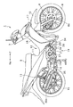
- FIG. 1 is a side view of a motorcycle according to a first embodiment of the present invention.
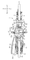
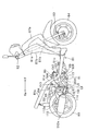
- FIG. 2 is a side view of the motorcycle of FIG. 1 with a vehicle body cover and the like removed.
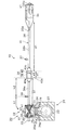
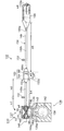
- FIG. 3 is a bottom view of FIG. 2.
- FIG. 2 is a control block diagram of the motorcycle of FIG. 1.
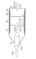
- FIG. 2 is a schematic diagram showing an engine body and an exhaust system of the motorcycle shown in FIG. 1.
- FIG. 6 is a side view of a motorcycle according to Modification 1-1 of Embodiment 1 with a body cover and the like removed.
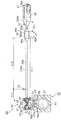
- FIG. 7 is a bottom view of FIG. 6.
- Fig. 7 is a schematic diagram showing an engine body and an exhaust system of the motorcycle shown in Fig. 6.
- FIG. 6 is a side view of a motorcycle according to Modification 1-2 of Embodiment 1 with a body cover and the like removed.
- Fig. 10 is a schematic diagram showing an engine body and an exhaust system of the motorcycle shown in Fig. 9. It is a side view of the motorcycle of Embodiment 2 of the present invention.
- FIG. 12 is a bottom view of FIG. 11.
- FIG. 12 is a side view of the motorcycle shown in FIG. 11 with a vehicle body cover and the like removed.
- FIG. 14 is a bottom view of FIG. 13.
- FIG. 12 is a schematic diagram showing an engine body and an exhaust system of the motorcycle shown in FIG. 11.
- FIG. 6 is a side view of a motorcycle according to Modification 2-1 of Embodiment 2 with a body cover and the like removed.
- FIG. 17 is a bottom view of FIG. 16.
- FIG. 17 is a schematic diagram showing an engine body and an exhaust system of the motorcycle shown in FIG. 16. It is a side view of the motorcycle of Embodiment 3 of the present invention.
- FIG. 20 is a bottom view of FIG. 19.
- FIG. 20 is a side view of the motorcycle shown in FIG. 19 with a vehicle body cover and the like removed. It is a bottom view of FIG.
- FIG. 20 is a schematic diagram showing an engine body and an exhaust system of the motorcycle shown in FIG. 19.
- FIG. 10 is a side view of a motorcycle according to Modification 3-1 of Embodiment 3 with a body cover and the like removed. It is a bottom view of FIG. Fig.
- FIG. 25 is a schematic diagram showing an engine body and an exhaust system of the motorcycle shown in Fig. 24. It is a side view of the motorcycle of Embodiment 4 of the present invention. It is a bottom view of FIG. FIG. 28 is a side view of the motorcycle of FIG. 27 with a vehicle body cover and the like removed. FIG. 30 is a bottom view of FIG. 29. FIG. 28 is a schematic diagram showing an engine body and an exhaust system of the motorcycle shown in FIG. 27.
- FIG. 10 is a side view of a motorcycle according to Modification 4-1 of Embodiment 4 with a body cover and the like removed. It is a bottom view of FIG. Fig. 33 is a schematic diagram showing an engine body and an exhaust system of the motorcycle shown in Fig. 32.
- FIG. 6 is a schematic diagram showing an engine body and an exhaust system of a motorcycle according to another embodiment of the present invention.
- FIG. 6 is a schematic view of an engine body of a motorcycle according to another embodiment of the present invention.
- FIG. 6 is a partial cross-sectional view of an exhaust pipe applied to a motorcycle according to another embodiment of the present invention.
- FIG. 6 is a partially enlarged view of a side view of a motorcycle according to another embodiment of the present invention.
- front, rear, left, and right mean front, rear, left, and right, respectively, as viewed from a motorcycle occupant. However, it is assumed that the motorcycle is placed on a horizontal ground.
- Reference numerals F, Re, L, and R attached to the drawings represent front, rear, left, and right, respectively.
- FIG. 1 is a side view of a motorcycle according to a first embodiment of the present invention.
- FIG. 2 is a side view of the motorcycle according to the first embodiment with a vehicle body cover and the like removed.
- FIG. 3 is a bottom view of the motorcycle according to the first embodiment with a vehicle body cover and the like removed.
- FIG. 5 is a schematic diagram showing an engine and an exhaust system of the motorcycle according to the first embodiment.
- the vehicle of the first embodiment is a so-called underbone type motorcycle 1.
- the motorcycle 1 includes a body frame 2.
- the vehicle body frame 2 includes a head pipe 3, a main frame 4, and a seat rail 5.
- the main frame 4 extends rearward and downward from the head pipe 3.
- the seat rail 5 extends rearward and upward from the middle part of the main frame 4.
- a steering shaft is rotatably inserted into the head pipe 3.
- a handle 7 (see FIG. 1) is provided on the upper portion of the steering shaft.
- a display device (not shown) is disposed in the vicinity of the handle 7. The display device displays vehicle speed, engine speed, various warnings, and the like.
- a pair of left and right front forks 6 are supported at the bottom of the steering shaft.
- An axle 8 a is fixed to the lower end portion of the front fork 6.
- a front wheel 8 is rotatably attached to the axle 8a.
- a fender 10 is provided above and behind the front wheel 8.
- a seat 9 (see FIG. 1) is supported on the seat rail 5.
- the seat rail 5 is connected to upper ends of a pair of left and right rear cushion units 13.
- the lower end portion of the rear cushion unit 13 is supported by the rear portions of the pair of left and right rear arms 14.
- the front portion of the rear arm 14 is connected to the vehicle body frame 2 via a pivot shaft 14a.
- the rear arm 14 can swing up and down around the pivot shaft 14a.
- a rear wheel 15 is supported at the rear portion of the rear arm 14.
- an engine body 20 is disposed below the main frame 4.
- the engine body 20 is supported by the body frame 2.
- the upper part of the engine body 20 is fixed to the bracket 4a provided on the main frame 4 by bolts 4b.
- an upper front portion of a crankcase portion 21 described later of the engine body 20 is fixed to the bracket 4a.
- the rear portion of the engine body 20 is also fixed to another bracket provided on the vehicle body frame 2.
- An air cleaner 32 is disposed below the main frame 4 and above the engine body 20.
- the motorcycle 1 has a vehicle body cover 11 that covers the vehicle body frame 2 and the like.
- the vehicle body cover 11 includes a main cover 16 and a front cover 17.
- the front cover 17 is disposed in front of the head pipe 3.
- the main cover 16 is disposed behind the head pipe 3.
- the main cover 16 covers the main frame 4 and the seat rail 5.
- the main cover 16 and the front cover 17 cover the left and right sides of the front portion of the engine body 20.
- the front cover 17 covers the left and right sides of the air cleaner 32.
- the main frame 4 and the vehicle body cover 11 have a low portion between the seat 9 and the head pipe 3.
- the underbone type motorcycle 1 has a recess 12 formed behind the head pipe 3, ahead of the seat 9 and above the main frame 4 when viewed from the left-right direction of the vehicle.
- the recess 12 makes it easier for the occupant to straddle the vehicle body.
- the motorcycle 1 has a single-cylinder four-stroke engine unit 19.
- the single-cylinder four-stroke engine unit 19 includes an engine body 20, an air cleaner 32, an intake pipe 33, an exhaust pipe 34, a silencer 35, a main catalyst 39 (single combustion chamber main catalyst), and upstream oxygen detection.
- a member 36 upstream oxygen detecting member for a single combustion chamber
- a downstream oxygen detecting member 37 downstream oxygen detecting member for a single combustion chamber
- the main catalyst 39 is disposed in the exhaust pipe 34.
- the main catalyst 39 purifies the exhaust gas flowing through the exhaust pipe 34.
- the upstream oxygen detection member 36 is disposed upstream of the main catalyst 39 in the exhaust pipe 34.
- the downstream oxygen detection member 37 is disposed downstream of the main catalyst 39 in the exhaust pipe 34.
- the upstream oxygen detection member 36 and the downstream oxygen detection member 37 detect the amount of oxygen or the oxygen concentration in the exhaust gas flowing through the exhaust pipe 34.
- the engine body 20 is a single-cylinder four-stroke engine. As shown in FIGS. 2 and 3, the engine main body 20 includes a crankcase portion 21 and a cylinder portion 22. The cylinder part 22 extends forward from the crankcase part 21.
- the crankcase portion 21 includes a crankcase body 23, a crankshaft 27 accommodated in the crankcase body 23, a transmission mechanism, and the like.
- the center line Cr1 of the crankshaft 27 is referred to as a crankshaft line Cr1.
- the crank axis Cr1 extends in the left-right direction.
- Lubricating oil is stored in the crankcase body 23. Such oil is conveyed by an oil pump (not shown) and circulates in the engine body 20.
- the cylinder part 22 has a cylinder body 24, a cylinder head 25, a head cover 26, and components housed therein. As shown in FIG. 2, the cylinder body 24 is connected to the front portion of the crankcase body 23. The cylinder head 25 is connected to the front part of the cylinder body 24. The head cover 26 is connected to the front part of the cylinder head 25.
- a cylinder hole 24 a is formed in the cylinder body 24.
- a piston 28 is accommodated in the cylinder hole 24a so as to be able to reciprocate.
- the piston 28 is connected to the crankshaft 27 via a connecting rod.
- the center line Cy1 of the cylinder hole 24a is referred to as a cylinder axis Cy1.
- the engine body 20 is arranged such that the cylinder axis Cy ⁇ b> 1 extends in the front-rear direction (horizontal direction). More specifically, the direction of the cylinder axis Cy1 from the crankcase portion 21 toward the cylinder portion 22 is front-upward.
- the inclination angle of the cylinder axis Cy1 with respect to the horizontal direction is not less than 0 degrees and not more than 45 degrees.
- one combustion chamber 29 is formed inside the cylinder portion 22.
- the combustion chamber 29 is formed by the inner surface of the cylinder hole 24 a of the cylinder body 24, the cylinder head 25, and the piston 28. That is, a part of the combustion chamber 29 is partitioned by the inner surface of the cylinder hole 24a.
- a tip end portion of a spark plug (not shown) is arranged in the combustion chamber 29.
- the spark plug ignites a mixed gas of fuel and air in the combustion chamber 29.
- the combustion chamber 29 is located in front of the crank axis Cr1. This is paraphrased as follows. A straight line passing through the crank axis Cr1 and extending in parallel with the vertical direction is defined as L1. When viewed from the left-right direction, the combustion chamber 29 is disposed in front of the straight line L1.
- the cylinder head 25 is formed with a cylinder intake passage portion 30 and a cylinder exhaust passage portion 31 (a cylinder exhaust passage portion for a single combustion chamber).
- the “passage part” is a structure that forms a space (path) through which gas or the like passes.
- an intake port 30 a and an exhaust port 31 a are formed in a wall portion that forms the combustion chamber 29.
- the cylinder intake passage portion 30 extends from the intake port 30 a to an intake port formed on the outer surface (upper surface) of the cylinder head 25.
- the cylinder exhaust passage 31 extends from the exhaust port 31 a to a discharge port formed on the outer surface (lower surface) of the cylinder head 25.
- Air supplied to the combustion chamber 29 passes through the cylinder intake passage portion 30.
- the exhaust gas discharged from the combustion chamber 29 passes through the cylinder exhaust passage portion 31.
- the cylinder intake passage 30 is provided with an intake valve V1.
- An exhaust valve V ⁇ b> 2 is disposed in the cylinder exhaust passage portion 31.
- the intake valve V ⁇ b> 1 and the exhaust valve V ⁇ b> 2 are operated by a valve operating mechanism (not shown) that is linked to the crankshaft 27.
- the intake port 30a is opened and closed by the movement of the intake valve V1.
- the exhaust port 31a is opened and closed by the movement of the exhaust valve V2.
- An intake pipe 33 is connected to an end (suction port) of the cylinder intake passage portion 30.
- An exhaust pipe 34 is connected to an end portion (discharge port) of the cylinder exhaust passage portion 31.
- the path length of the cylinder exhaust passage portion 31 is a1.
- an injector 48 (see FIG. 4) is arranged in the cylinder intake passage 30 or the intake pipe 33.
- the injector 48 is for supplying fuel to the combustion chamber 29. More specifically, the injector 48 injects fuel in the cylinder intake passage portion 30 or the intake pipe 33.
- the injector 48 may be disposed so as to inject fuel into the combustion chamber 29.
- a throttle valve (not shown) is disposed in the intake pipe 33.
- the intake pipe 33 extends upward from the upper surface of the cylinder head 25 when viewed from the left-right direction.
- the intake pipe 33 is connected to the air cleaner 32.
- the air cleaner 32 purifies the air supplied to the engine body 20. Air purified by passing through the air cleaner 32 is supplied to the engine body 20 through the intake pipe 33.
- FIG. 4 is a control block diagram of the motorcycle according to the first embodiment.
- the single-cylinder four-stroke engine unit 19 includes an engine speed sensor 46a, a throttle opening sensor 46b (throttle position sensor), an engine temperature sensor 46c, an intake pressure sensor 46d, and an intake temperature sensor 46e.
- the engine rotation speed sensor 46a detects the rotation speed of the crankshaft 27, that is, the engine rotation speed.
- the throttle opening sensor 46b detects the opening of the throttle valve (hereinafter referred to as the throttle opening) by detecting the position of a throttle valve (not shown).
- the engine temperature sensor 46c detects the temperature of the engine body.
- the intake pressure sensor 46d detects the pressure (intake pressure) in the intake pipe 33.
- the intake air temperature sensor 46e detects the temperature of air in the intake pipe 33 (intake air temperature).
- the single-cylinder four-stroke engine unit 19 includes an electronic control unit (ECU: Electronic Control Unit) 45 that controls the engine body 20.
- the electronic control unit 45 corresponds to the control device of the present invention.
- the electronic control unit 45 is connected to various sensors such as an engine speed sensor 46a, an engine temperature sensor 46c, a throttle opening sensor 46b, an intake pressure sensor 46d, an intake air temperature sensor 46e, and a vehicle speed sensor.
- the electronic control unit 45 is connected to an ignition coil 47, an injector 48, a fuel pump 49, a display device (not shown), and the like.
- the electronic control unit 45 includes a control unit 45a and an operation instruction unit 45b.
- the operation instructing unit 45b includes an ignition drive circuit 45c, an injector drive circuit 45d, and a pump drive circuit 45e.
- the ignition drive circuit 45c, the injector drive circuit 45d, and the pump drive circuit 45e drive the ignition coil 47, the injector 48, and the fuel pump 49, respectively, in response to a signal from the control unit 45a.
- the fuel pump 49 is connected to the injector 48 via a fuel hose.
- fuel in a fuel tank (not shown) is pumped to the injector 48.
- the control unit 45a is, for example, a microcomputer.
- the controller 45a controls the ignition drive circuit 45c, the injector drive circuit 45d, and the pump drive circuit 45e based on the signal from the upstream oxygen detection member 36 and the signal from the engine rotation speed sensor 46a.
- the controller 45a controls the ignition timing by controlling the ignition drive circuit 45c.
- the controller 45a controls the fuel injection amount by controlling the injector drive circuit 45d and the pump drive circuit 45e.
- the air-fuel ratio of the air-fuel mixture in the combustion chamber 29 is preferably the stoichiometric air-fuel ratio (stoichiometry).
- the controller 45a increases or decreases the fuel injection amount as necessary.
- the controller 45a calculates the basic fuel injection amount based on signals from the engine speed sensor 46a, the throttle opening sensor 46b, the engine temperature sensor 46c, and the intake pressure sensor 46d. Specifically, the intake air amount is calculated using a map in which the intake air amount is associated with the throttle opening and the engine rotational speed, and a map in which the intake air amount is associated with the intake pressure and the engine rotational speed. Ask. Then, based on the intake air amount obtained from the map, the basic fuel injection amount that can achieve the target air-fuel ratio is determined. When the throttle opening is small, a map in which the intake air amount is associated with the intake pressure and the engine speed is used. On the other hand, when the throttle opening is large, a map in which the intake air amount is associated with the throttle opening and the engine speed is used.
- control unit 45a calculates a feedback correction value for correcting the basic fuel injection amount based on the signal of the upstream oxygen detection member 36. Specifically, first, based on the signal from the upstream oxygen detection member 36, it is determined whether the air-fuel mixture is lean or rich. Note that rich means that the fuel is excessive with respect to the stoichiometric air-fuel ratio. Lean means a state where air is excessive with respect to the stoichiometric air-fuel ratio. When determining that the air-fuel mixture is lean, the control unit 45a calculates a feedback correction value so that the next fuel injection amount increases. On the other hand, when determining that the air-fuel mixture is rich, the control unit 45a obtains a feedback correction value so that the next fuel injection amount is reduced.
- control unit 45a calculates a correction value for correcting the basic fuel injection amount based on the engine temperature, the outside air temperature, the outside air pressure, and the like. Furthermore, the control unit 45a calculates a correction value according to the transient characteristics during acceleration and deceleration.
- the control unit 45a calculates the fuel injection amount based on the basic fuel injection amount and a correction value such as a feedback correction value. Based on the fuel injection amount thus determined, the fuel pump 49 and the injector 48 are driven. In this way, the electronic control unit 45 (control device) processes the signal of the upstream oxygen detection member 36. The electronic control unit 45 (control device) performs combustion control based on the signal from the upstream oxygen detection member 36.
- the electronic control unit 45 processes the signal of the downstream oxygen detection member 37.
- the electronic control unit 45 determines the purification capacity of the main catalyst 39 based on the signal from the downstream oxygen detection member 37.
- an example of a specific method for determining the purification ability of the main catalyst 39 based on the signal from the downstream oxygen detection member 37 will be described.
- the fuel injection amount is controlled so that the mixed gas repeats rich and lean for a certain period (several seconds). And the delay of the change of the signal of the downstream oxygen detection member 37 with respect to the change of the fuel injection amount is detected.
- the delay of the signal change of the downstream oxygen detection member 37 is large, it is determined that the purification capacity of the main catalyst 39 has decreased from a predetermined level.
- a signal is sent from the electronic control unit 45 to the display device. Then, a warning light (not shown) of the display device is turned on. Thereby, it is possible to prompt the passenger to replace the main catalyst 39.
- the purification ability of the main catalyst 39 can be determined by using the signal of the downstream oxygen detection member 37 disposed downstream of the main catalyst 39. Therefore, notification can be made before the deterioration of the main catalyst 39 reaches a predetermined level, and the replacement of the main catalyst 39 can be urged. As a result, the initial performance of exhaust purification of the motorcycle 1 can be maintained for a longer period using a plurality of main catalysts.
- upstream means upstream in the flow direction of exhaust gas.
- downstream means downstream in the flow direction of the exhaust gas.
- the path direction is the direction in which exhaust gas flows.
- the single cylinder four-stroke engine unit 19 includes the engine body 20, the exhaust pipe 34, the silencer 35, the main catalyst 39, the upstream oxygen detection member 36, and the downstream oxygen detection member 37. Yes.
- the silencer 35 has a discharge port 35e facing the atmosphere.
- a path from the combustion chamber 29 to the discharge port 35e is an exhaust path 41 (see FIG. 5).
- the exhaust path 41 is formed by the cylinder exhaust passage portion 31, the exhaust pipe 34, and the silencer 35.
- the exhaust path 41 is a space through which exhaust gas passes.
- the upstream end portion of the exhaust pipe 34 is connected to the cylinder exhaust passage portion 31.
- the downstream end of the exhaust pipe 34 is connected to a silencer 35.
- a catalyst unit 38 is provided in the middle of the exhaust pipe 34.
- a portion of the exhaust pipe 34 upstream from the catalyst unit 38 is referred to as an upstream exhaust pipe 34a.
- a portion of the exhaust pipe 34 downstream from the catalyst unit 38 is referred to as a downstream exhaust pipe 34b.
- the exhaust pipe 34 is drawn in a straight line for simplification, but the exhaust pipe 34 is not straight.
- the exhaust pipe 34 is provided in the right part of the motorcycle 1. As shown in FIG. 2, a part of the exhaust pipe 34 is positioned below the crank axis Cr1.
- the exhaust pipe 34 has two bent portions. Of the two bent portions, the upstream bent portion is simply referred to as an upstream bent portion. Of the two bent portions, the downstream bent portion is simply referred to as a downstream bent portion.
- the upstream bent portion changes the flow direction of the exhaust gas from the direction extending in the vertical direction to the direction extending in the front-rear direction when viewed from the left-right direction. More specifically, the bent portion changes the flow direction of the exhaust gas from downward to rearward as viewed from the left-right direction.
- the downstream bent portion changes the flow direction of the exhaust gas from the rear upward direction to the rear direction when viewed from the left-right direction.
- a portion slightly downstream from the downstream bent portion is positioned below the crank axis Cr1.
- the main catalyst 39 is disposed between the two bent portions.
- the silencer 35 is connected to the exhaust pipe 34.
- the silencer 35 is configured to suppress pulsating waves of exhaust gas. Thereby, the silencer 35 can reduce the volume of the sound (exhaust sound) generated by the exhaust gas.
- a plurality of expansion chambers and a plurality of pipes communicating the expansion chambers are provided in the silencer 35.
- the downstream end of the exhaust pipe 34 is disposed in the expansion chamber of the silencer 35.
- a discharge port 35e facing the atmosphere is provided at the downstream end of the silencer 35. As shown in FIG. 5, the path length of the exhaust path from the downstream end of the exhaust pipe 34 to the discharge port 35e is defined as e1.
- the path length of the expansion chamber in the silencer 35 is the length of the path connecting the center of the expansion chamber inlet to the center of the expansion chamber outlet at the shortest distance.
- the exhaust gas that has passed through the silencer 35 is discharged to the atmosphere from the discharge port 35e. As shown in FIG. 2, the discharge port 35e is located behind the crank axis Cr1.
- the main catalyst 39 is disposed in the exhaust pipe 34.
- the upstream end of the main catalyst 39 is disposed upstream of the upstream end 35 a of the silencer 35.
- the catalyst unit 38 includes a cylindrical casing 40 and a main catalyst 39.
- the upstream end of the casing 40 is connected to the upstream exhaust pipe 34a.
- the downstream end of the casing 40 is connected to the downstream exhaust pipe 34b.
- the casing 40 constitutes a part of the exhaust pipe 34.
- the main catalyst 39 is fixed inside the casing 40.
- the exhaust gas is purified by passing through the main catalyst 39. All exhaust gas discharged from the exhaust port 31 a of the combustion chamber 29 passes through the main catalyst 39.
- the main catalyst 39 purifies the exhaust gas discharged from the combustion chamber 29 most in the exhaust path 41.
- the main catalyst 39 is a so-called three-way catalyst.
- the three-way catalyst is removed by oxidizing or reducing three substances of hydrocarbon, carbon monoxide, and nitrogen oxide contained in the exhaust gas.
- the three-way catalyst is one type of redox catalyst.
- the main catalyst 39 has a base material and a catalytic material attached to the surface of the base material.
- the catalytic material has a support and a noble metal.
- the carrier is provided between the noble metal and the substrate.
- the carrier carries a noble metal. This noble metal purifies the exhaust gas. Examples of the noble metal include platinum, palladium, and rhodium that remove hydrocarbons, carbon monoxide, and nitrogen oxides, respectively.
- the main catalyst 39 has a porous structure.
- the porous structure refers to a structure in which a hole is formed in a cross section perpendicular to the path direction of the exhaust path 41.
- An example of the porous structure is a honeycomb structure.
- the main catalyst 39 has a plurality of holes sufficiently narrower than the path width of the upstream exhaust pipe 34a.
- the main catalyst 39 may be a metal base catalyst or a ceramic base catalyst.
- the metal base catalyst is a catalyst whose base is made of metal.
- the ceramic base catalyst is a catalyst whose base is made of ceramic.
- the base material of the metal base catalyst is formed, for example, by alternately stacking and winding metal corrugated plates and metal flat plates.
- the base material of the ceramic base catalyst is, for example, a honeycomb structure.
- the length of the main catalyst 39 in the path direction is c1.
- the maximum width in the direction perpendicular to the path direction of the main catalyst 39 is w1.
- the length c1 of the main catalyst 39 is longer than the maximum width w1 of the main catalyst 39.
- the cross-sectional shape orthogonal to the path direction of the main catalyst 39 is, for example, a circular shape.
- the cross-sectional shape may be a shape in which the horizontal length is longer than the vertical length.
- the casing 40 includes a catalyst arrangement passage portion 40b, an upstream passage portion 40a, and a downstream passage portion 40c.
- the main catalyst 39 is arranged in the catalyst arrangement passage portion 40b.
- the upstream end and the downstream end of the catalyst arrangement passage portion 40 b are at the same positions as the upstream end and the downstream end of the main catalyst 39, respectively.
- the area of the cross section perpendicular to the path direction of the catalyst arrangement passage portion 40b is substantially constant in the path direction.
- the upstream passage portion 40a is connected to the upstream end of the catalyst arrangement passage portion 40b.
- the downstream passage portion 40c is connected to the upstream end of the catalyst arrangement passage portion 40b.
- the upstream passage portion 40a is at least partially tapered.
- the tapered portion has an inner diameter that increases toward the downstream.
- the downstream passage portion 40c is at least partially tapered.
- the tapered portion has an inner diameter that decreases toward the downstream.
- the area of the cross section orthogonal to the path direction of the catalyst arrangement passage portion 40b is S1.
- the area of the cross section orthogonal to the route direction of at least a part of the upstream passage portion 40a is smaller than the area S1.
- at least a part of the upstream passage portion 40a includes the upstream end of the upstream passage portion 40a.
- the area of the cross section perpendicular to the path direction of at least a part of the downstream passage portion 40c is smaller than the area S1.
- at least a part of the downstream passage portion 40c includes the downstream end of the downstream passage portion 40c.
- the main catalyst 39 is disposed in front of the crank axis Cr1. That is, the main catalyst 39 is disposed in front of the straight line L1 when viewed from the left-right direction. As described above, the straight line L1 is a straight line that passes through the crank axis Cr1 and extends parallel to the vertical direction. Further, the main catalyst 39 is located in front (downward) of the cylinder axis Cy1 when viewed from the left-right direction.
- L2 be a straight line that is orthogonal to the cylinder axis Cy1 and orthogonal to the crank axis Cr1.
- the main catalyst 39 is located in front of the straight line L2.
- the path length from the upstream end of the exhaust pipe 34 to the upstream end of the main catalyst 39 is b1.
- the path length b ⁇ b> 1 is the path length of the passage portion including the upstream exhaust pipe 34 a and the upstream passage portion 40 a of the catalyst unit 38.
- the path length b1 is the path length from the downstream end of the cylinder exhaust passage portion 31 to the upstream end of the main catalyst 39.
- the path length from the downstream end of the main catalyst 39 to the downstream end of the exhaust pipe 34 is defined as d1.
- the path length d1 is the path length of the passage portion including the downstream passage portion 40c and the downstream exhaust pipe 34b of the catalyst unit 38.
- the path length from the combustion chamber 29 to the upstream end of the main catalyst 39 is a1 + b1.
- the path length from the downstream end of the main catalyst 39 to the discharge port 35e is d1 + e1.
- the main catalyst 39 is disposed at a position where the path length a1 + b1 is shorter than the path length d1 + e1.
- the main catalyst 39 is disposed at a position where the path length a1 + b1 is shorter than the path length d1. Further, the main catalyst 39 is disposed at a position where the path length b1 is shorter than the path length d1.
- the upstream oxygen detection member 36 is disposed in the exhaust pipe 34.
- the upstream oxygen detection member 36 is disposed upstream of the main catalyst 39.
- the upstream oxygen detection member 36 is disposed in the upstream exhaust pipe 34a (see FIG. 5).
- the upstream oxygen detection member 36 is a sensor that detects the concentration of oxygen contained in the exhaust gas.
- the upstream oxygen detection member 36 may be an oxygen sensor that detects whether the oxygen concentration is higher or lower than a predetermined value.
- the upstream oxygen detection member 36 may be a sensor (for example, an A / F sensor: Air Fuel ratio sensor) that outputs a detection signal representing the oxygen concentration in a plurality of stages or linearly.
- the upstream oxygen detection member 36 has one end (detection unit) disposed in the exhaust pipe 34 and the other end disposed outside the exhaust pipe 34.
- the detection unit of the upstream oxygen detection member 36 can detect the oxygen concentration when the detection unit is heated to a high temperature and activated.
- the detection result of the upstream oxygen detection member 36 is output to the electronic control unit 45.
- the path length from the combustion chamber 29 to the upstream oxygen detection member 36 is h1.
- the path length from the upstream oxygen detection member 36 to the upstream end of the main catalyst 39 is h2.
- the upstream oxygen detection member 36 is disposed at a position where the path length h1 is shorter than the path length h2.
- the downstream oxygen detection member 37 is disposed in the exhaust pipe 34.
- the downstream oxygen detection member 37 is disposed downstream of the main catalyst 39.
- the downstream oxygen detection member 37 is disposed in the downstream exhaust pipe 34b (see FIG. 5).
- the downstream oxygen detection member 37 is disposed upstream of the silencer 35.
- the downstream oxygen detection member 37 is a sensor that detects the oxygen concentration contained in the exhaust gas.
- the downstream oxygen detection member 37 may be an oxygen sensor that detects whether the oxygen concentration is higher or lower than a predetermined value.
- the downstream oxygen detection member 37 may be a sensor (for example, an A / F sensor: Air Fuel ratio sensor) that outputs a detection signal representing the oxygen concentration in a plurality of steps or linearly.
- the downstream oxygen detection member 37 has one end (detection unit) disposed in the exhaust pipe 34 and the other end disposed outside the exhaust pipe 34. The detection result of the downstream oxygen detection member 37 is output to the electronic control unit 45.
- the configuration of the motorcycle 1 according to the first embodiment has been described above.
- the motorcycle 1 of the first embodiment has the following characteristics.
- At least a part of the combustion chamber 29 is disposed in front of the crank axis Cr1.
- the discharge port 35e of the silencer 35 is disposed behind the crank axis Cr1.
- the main catalyst 39 is at least partially disposed in front of the crank axis Cr1.
- the upstream end of the main catalyst 39 is disposed upstream of the upstream end 35 a of the silencer 35. That is, the main catalyst 39 is disposed at a position relatively close to the combustion chamber 29. Therefore, the exhaust gas purification performance of the main catalyst 39 can be improved.
- the downstream oxygen detection member 37 is disposed downstream from the main catalyst 39. Deterioration of the main catalyst 39 can be detected based on the signal from the downstream oxygen detection member 37. Accordingly, it is possible to notify the user before the deterioration of the main catalyst 39 reaches a predetermined level and prompt the user to replace the main catalyst 39. As a result, the initial performance of the exhaust purification of the motorcycle 1 can be maintained for a longer period by using the plurality of main catalysts 39. Further, the deterioration of the main catalyst 39 may be detected based on the signal of the downstream oxygen detection member 37 and the signal of the upstream oxygen detection member 36 disposed upstream of the main catalyst 39.
- the degree of deterioration of the main catalyst 39 can be detected with higher accuracy. Therefore, as compared with the case where the deterioration of the main catalyst 39 is detected using only the signal of the downstream oxygen detection member 37, one main catalyst 39 is maintained for a longer period of time while maintaining the initial performance of exhaust purification of the motorcycle 1. Can be used.
- the actual purification capacity of the main catalyst 39 can be detected from the signal of the upstream oxygen detection member 36 disposed upstream of the main catalyst 39 and the signal of the downstream oxygen detection member 37 disposed downstream of the main catalyst 39. Therefore, when the combustion control is performed based on the signals of the two oxygen detection members 36 and 37, the accuracy of the combustion control can be improved. Thereby, the progress of deterioration of the main catalyst 39 can be delayed. Therefore, the initial performance of exhaust purification of the motorcycle 1 can be maintained for a longer period. As described above, the initial performance of the exhaust purification of the motorcycle 1 can be maintained for a longer period without increasing the size of the main catalyst 39. Therefore, the initial performance of exhaust purification of the motorcycle 1 can be maintained for a long time while simplifying the support structure.
- the motorcycle 1 including the single-cylinder four-stroke engine unit 19 of the present embodiment improves the exhaust gas purification performance by the catalyst while simplifying the support structure, and the initial performance of the motorcycle 1 for exhaust gas purification. Can be maintained for a long time.
- the main catalyst 39 is at least partially disposed in front of the crank axis Cr1. Therefore, the main catalyst 39 is disposed at a position closer to the combustion chamber 29. Therefore, the exhaust gas purification performance by the main catalyst 39 can be further improved.
- the straight line L2 is a straight line that is orthogonal to the cylinder axis Cy1 and orthogonal to the crank axis Cr1.
- the straight line L2 extends downward from the crankshaft 27.
- at least a part of the main catalyst 39 is located in front of the straight line L2. Therefore, the main catalyst 39 is disposed at a position closer to the combustion chamber 29. Therefore, the exhaust gas purification performance of the main catalyst 39 can be further improved.
- the path length (a1 + b1) from one combustion chamber 29 to the upstream end of the main catalyst 39 is shorter than the path length (d1 + e1) from the downstream end of the main catalyst 39 to the discharge port 35e. Therefore, the main catalyst 39 can be disposed at a position closer to the combustion chamber 29. Therefore, the exhaust gas purification performance of the main catalyst 39 can be further improved.
- the path length (a1 + b1) from one combustion chamber 29 to the upstream end of the main catalyst 39 is shorter than the path length (d1) from the downstream end of the main catalyst 39 to the downstream end of the exhaust pipe 34. Therefore, the main catalyst 39 can be disposed at a position closer to the combustion chamber 29. Therefore, the exhaust gas purification performance of the main catalyst 39 can be further improved.
- the path length (h1) from one combustion chamber 29 to the upstream end of the upstream oxygen detection member 36 is shorter than the path length (h2) from the upstream oxygen detection member 36 to the upstream end of the main catalyst 39. Therefore, the upstream oxygen detection member is disposed at a position closer to the combustion chamber 29. Therefore, the upstream oxygen detection member 36 can be raised to the activation temperature earlier when the engine is started. Therefore, the detection accuracy of the upstream oxygen detection member 36 can be improved. Thereby, the combustion control based on the signal of the upstream oxygen detection member 36 can be performed with higher accuracy. As a result, the exhaust gas purification performance of the main catalyst 39 can be further improved. Further, the progress of deterioration of the main catalyst 39 can be delayed by improving the accuracy of the combustion control. Therefore, the initial performance of exhaust purification of the motorcycle 1 can be maintained for a longer period.
- the area of the cross section orthogonal to the flow direction of at least a part of the exhaust gas in the upstream passage 40a is smaller than the area S1.
- the area S1 is an area of a cross section orthogonal to the flow direction of the exhaust gas in the catalyst arrangement passage portion 40b. Therefore, a catalyst having a large cross-sectional area can be used as the main catalyst 39. Therefore, the exhaust gas purification performance of the main catalyst 39 can be improved.
- FIG. 6 is a side view of the motorcycle according to the modified example 1-1 of the first embodiment with the vehicle body cover and the like removed.
- FIG. 7 is a bottom view of the motorcycle according to the modified example 1-1 of the first embodiment with the vehicle body cover and the like removed.
- FIG. 8 is a schematic diagram showing an engine body and an exhaust system of Modification 1-1 of Embodiment 1.
- the same components as those of the first embodiment are denoted by the same reference numerals, and detailed description thereof is omitted.
- the main catalyst 39 is arranged downstream of the first embodiment.
- the specific configuration of the main catalyst 39 is the same as that of the first embodiment.
- the main catalyst 39 of Modification 1-1 is disposed in the exhaust pipe 234.
- the upstream end of the main catalyst 39 is disposed upstream of the upstream end 35 a of the silencer 35.
- the exhaust pipe 234 is connected to the cylinder exhaust passage portion 31 (see FIG. 8) and the silencer 35 in the same manner as the exhaust pipe 34 of the first embodiment.
- a catalyst unit 38 is provided in the middle of the exhaust pipe 234.
- a portion of the exhaust pipe 234 upstream from the catalyst unit 38 is referred to as an upstream exhaust pipe 234a.
- a portion of the exhaust pipe 234 downstream from the catalyst unit 38 is referred to as a downstream exhaust pipe 234b.
- the downstream exhaust pipe 234 b is disposed in the silencer 35.
- the exhaust pipe 234 is drawn in a straight line for simplification, but the exhaust pipe 234 is not in a straight line.
- the main catalyst 39 is disposed behind the crank axis Cr1. That is, the main catalyst 39 is disposed behind the straight line L1 when viewed from the left-right direction. As described above, the straight line L1 is a straight line that passes through the crank axis Cr1 and extends parallel to the vertical direction. Further, the main catalyst 39 is located in front (downward) of the cylinder axis Cy1 when viewed from the left-right direction.
- the main catalyst 39 is located in front of the straight line L2 when viewed from the left-right direction.
- the straight line L2 is a straight line that is orthogonal to the cylinder axis Cy1 and orthogonal to the crank axis Cr1.
- the path length from the upstream end of the exhaust pipe 234 to the upstream end of the main catalyst 39 is b11.
- the path length from the downstream end of the main catalyst 39 to the downstream end of the exhaust pipe 234 is defined as d11.
- the path length from the combustion chamber 29 to the upstream end of the main catalyst 39 is a1 + b11.
- the path length from the downstream end of the main catalyst 39 to the discharge port 35e is d11 + e1.
- the main catalyst 39 of the modified example 1-1 is disposed at a position where the path length a1 + b11 is shorter than the path length d11 + e1. Further, unlike the first embodiment, the main catalyst 39 of Modification 1-1 is disposed at a position where the path length a1 + b11 is longer than the path length d11. Further, unlike the first embodiment, the main catalyst 39 of the modified example 1-1 is disposed at a position where the path length b11 is longer than the path length d11.
- the upstream oxygen detection member 36 is disposed in the exhaust pipe 234.
- the upstream oxygen detection member 36 is disposed upstream of the main catalyst 39.
- the upstream oxygen detection member 36 is disposed in the upstream exhaust pipe 234a (see FIG. 8).
- the path length from the combustion chamber 29 to the upstream oxygen detection member 36 is h11.
- the path length from the upstream oxygen detection member 36 to the upstream end of the main catalyst 39 is h12.
- the upstream oxygen detection member 36 is disposed at a position where the path length h11 is shorter than the path length h12.
- the downstream oxygen detection member 37 is disposed in the exhaust pipe 234.
- the downstream oxygen detection member 37 is disposed downstream of the main catalyst 39.
- the downstream oxygen detection member 37 is disposed in the downstream exhaust pipe 234a (see FIG. 8).
- the downstream oxygen detection member 37 passes through the side wall portion of the silencer 35.
- One end (detection unit) of the downstream oxygen detection member 37 is disposed in the downstream exhaust pipe 234a.
- the other end of the downstream oxygen detection member 37 is disposed outside the silencer 35.
- FIG. 9 is a side view of the motorcycle according to the modified example 1-2 of the first embodiment.
- FIG. 10 is a schematic diagram showing an engine body and an exhaust system of a modified example 1-2 of the first embodiment.
- the same components as those in the first embodiment are denoted by the same reference numerals, and detailed description thereof is omitted.
- the upstream sub catalyst 300 upstream sub catalyst for the single combustion chamber
- the main catalyst 39 the upstream oxygen detection member 36
- the downstream oxygen detection member 37 are arranged in the exhaust pipe 334.
- the exhaust pipe 334 is connected to the cylinder exhaust passage portion 31 (see FIG. 10) and the silencer 35 in the same manner as the exhaust pipe 34 of the first embodiment.
- a catalyst unit 38 is provided in the middle of the exhaust pipe 334.
- a portion of the exhaust pipe 334 upstream of the catalyst unit 38 is referred to as an upstream exhaust pipe 334a.
- a portion of the exhaust pipe 334 downstream from the catalyst unit 38 is referred to as a downstream exhaust pipe 334b.
- the exhaust pipe 334 is drawn in a straight line for simplification, but the exhaust pipe 334 is not in a straight line.
- the upstream sub-catalyst 300 is provided upstream from the main catalyst 39.
- the upstream sub-catalyst 300 is provided in the upstream exhaust pipe 334a (exhaust pipe 334).
- the upstream sub-catalyst 300 may be composed of only the catalyst material attached to the inner wall of the exhaust pipe 334.
- the base material to which the catalytic material of the upstream sub-catalyst 300 is attached is the inner wall of the exhaust pipe 334.
- the upstream sub-catalyst 300 may have a base material arranged inside the exhaust pipe 334.
- the upstream sub-catalyst 300 includes a base material and a catalyst material.
- the base material of the upstream sub-catalyst 300 is, for example, a plate shape.
- the shape of the cross section orthogonal to the path direction of the plate-like substrate may be S-shaped, circular, or C-shaped. Regardless of whether the upstream sub-catalyst 300 has a base material or not, the upstream sub-catalyst 300 does not have a porous structure. Therefore, the upstream sub-catalyst 300 has a smaller action that causes reflection of pressure pulsation due to exhaust gas than the main catalyst 39. Further, the upstream sub-catalyst 200 has a lower resistance to the flow of exhaust gas than the main catalyst 39.
- the main catalyst 39 most purifies the exhaust gas discharged from the combustion chamber 29 in the exhaust passage 41. That is, the main catalyst 39 purifies the exhaust gas discharged from the combustion chamber 29 in the exhaust path 41 rather than the upstream sub catalyst 300. In other words, the upstream sub-catalyst 300 has a lower contribution to purify the exhaust gas than the main catalyst 39.
- the respective contributions of purification of the main catalyst 39 and the upstream sub-catalyst 300 can be measured by the following method.
- a catalyst disposed upstream is referred to as a front catalyst
- a catalyst disposed downstream is referred to as a rear catalyst.
- the upstream sub-catalyst 300 is a front catalyst
- the main catalyst 39 is a rear catalyst.
- the engine unit of the first modification is operated, and the concentration of harmful substances contained in the exhaust gas discharged from the discharge port 35e in the warm-up state is measured.
- the exhaust gas measurement method shall be in accordance with European regulations.
- the main catalyst 39 and the upstream sub-catalyst 200 are activated at a high temperature. Therefore, the main catalyst 39 and the upstream sub-catalyst 200 can sufficiently exhibit purification performance when in the warm-up state.
- the engine unit in this state is referred to as a measurement engine unit A.
- emitted from the discharge port 35e at the time of a warm-up state is measured.
- the front catalyst of this measurement engine unit A is removed, and only the base material of the front catalyst is arranged instead.
- the engine unit in this state is referred to as a measurement engine unit B.
- emitted from the discharge port 35e at the time of a warm-up state is measured.
- the upstream sub-catalyst 200 front catalyst
- the exhaust pipe 234 corresponds to the base material.
- the arrangement of only the base material of the upstream sub-catalyst 200 in place of the upstream sub-catalyst 200 is to prevent the catalyst material from adhering to the inner wall of the exhaust pipe 234.
- the measurement engine unit A has a front catalyst and does not have a rear catalyst.
- the measurement engine unit B does not have a front catalyst and a rear catalyst. Therefore, the degree of contribution of the purification of the front catalyst (upstream sub-catalyst 300) is calculated from the difference between the measurement result of the measurement engine unit A and the measurement result of the measurement engine unit B. Further, the degree of contribution of the purification of the rear catalyst (main catalyst 39) is calculated from the difference between the measurement result of the measurement engine unit A and the measurement result of the engine unit of Modification 1-2.
- the purification capacity of the upstream sub-catalyst 200 may be smaller or larger than the purification capacity of the main catalyst 39.
- the purification capacity of the upstream sub catalyst 200 is smaller than the purification capacity of the main catalyst 39.
- the exhaust gas purification rate when only the upstream sub catalyst 200 is provided is the purification of exhaust gas when only the main catalyst 39 is provided. That is less than the rate.
- the main catalyst 39 is disposed in front of the crank axis Cr1. Further, the main catalyst 39 is located in front of the straight line L2 when viewed from the left-right direction.
- the definition of the straight line L2 is the same as that in the first embodiment. That is, the straight line L2 is a straight line that is orthogonal to the cylinder axis Cy1 and orthogonal to the crank axis Cr1.
- the path length from the upstream end of the exhaust pipe 334 to the upstream end of the main catalyst 39 is b21.
- the path length from the downstream end of the main catalyst 39 to the downstream end of the exhaust pipe 334 is defined as d21.
- the path length from the combustion chamber 29 to the upstream end of the main catalyst 39 is a1 + b21.
- the path length from the downstream end of the main catalyst 39 to the discharge port 35e is d21 + e1.
- the main catalyst 39 is disposed at a position where the path length a1 + b21 is shorter than the path length d21 + e1. Similarly to the first embodiment, the main catalyst 39 is disposed at a position where the path length a1 + b21 is shorter than the path length d21. Further, as in the first embodiment, the main catalyst 39 is disposed at a position where the path length b21 is shorter than the path length d21.
- the upstream oxygen detection member 36 is disposed in the exhaust pipe 334.
- the upstream oxygen detection member 36 is disposed upstream of the upstream sub catalyst 300.
- the upstream oxygen detection member 36 is disposed in the upstream exhaust pipe 334a (see FIG. 13).
- the path length from the combustion chamber 29 to the upstream oxygen detection member 36 is h21.
- the path length from the upstream oxygen detection member 36 to the upstream end of the main catalyst 39 is h22. Similar to the first embodiment, the upstream oxygen detection member 36 is disposed at a position where the path length h21 is shorter than the path length h22.
- the downstream oxygen detection member 37 is disposed in the exhaust pipe 334.
- the downstream oxygen detection member 37 is disposed downstream of the main catalyst 39.
- the downstream oxygen detection member 37 is disposed in the downstream exhaust pipe 334b (see FIG. 13).
- the downstream oxygen detection member 37 is disposed upstream of the silencer 35.
- the upstream sub-catalyst 300 is provided upstream from the main catalyst 39.
- the upstream sub-catalyst 300 progresses faster than the main catalyst 39.
- the main catalyst 39 can maintain the exhaust gas purification performance. Therefore, it is possible to maintain the initial performance of exhaust purification of the motorcycle for a longer time.
- the upstream oxygen detection member 36 is disposed upstream of the upstream sub-catalyst 300. Therefore, the upstream oxygen detection member 36 can detect the oxygen concentration of the exhaust gas flowing into the upstream sub catalyst 300. Therefore, the exhaust gas purification performance by the upstream sub-catalyst 300 can be enhanced by performing combustion control based on the signal of the upstream oxygen detection member 36.
- FIG. 11 is a side view of the motorcycle according to the second embodiment of the present invention.
- FIG. 12 is a bottom view of the motorcycle according to the second embodiment.
- FIG. 13 is a side view of the motorcycle according to the second embodiment with a body cover and the like removed.
- FIG. 14 is a bottom view of the motorcycle according to the second embodiment with a body cover and the like removed.
- FIG. 15 is a schematic diagram showing an engine and an exhaust system of the motorcycle according to the second embodiment.
- the vehicle according to the second embodiment is a so-called street type motorcycle 50.
- the motorcycle 50 includes a vehicle body frame 53.
- the vehicle body frame 53 includes a head pipe 53a, an upper main frame 53b, a lower main frame 53c, and a seat frame 53d.
- the upper main frame 53b extends rearward and downward from the head pipe 53a, and then curves downward and extends downward.
- the lower main frame 53c is located below the upper main frame 53b.
- the lower main frame 53c extends rearward and downward from the head pipe 53a.
- the seat frame 53d extends rearward from the middle part of the upper main frame 53b.
- a steering shaft is rotatably inserted into the head pipe 53a.
- a handle 55 is provided on the upper portion of the steering shaft.
- a display device (not shown) is disposed in the vicinity of the handle 55. The display device displays vehicle speed, engine speed, various warnings, and the like.
- the upper and lower ends of the steering shaft are connected to a pair of left and right front forks 56 via brackets.
- a front wheel 57 is rotatably supported at the lower end of the front fork 56.
- the front end of a pair of left and right rear arms 58 is swingably supported at the rear of the vehicle body frame 53.
- a rear wheel 59 is rotatably supported at the rear end portion of the rear arm 58.
- a fuel tank 51 (see FIG. 11) is supported on the upper main frame 53b.
- a seat 52 (see FIG. 11) is supported on the seat frame 53d.
- An engine body 61 is supported on the body frame 53.
- An air cleaner 73 (see FIG. 13) is supported on the body frame 53. As shown in FIG. 13, when viewed from the left-right direction, the upper portion of the engine body 61 is disposed between the upper main frame 53b and the lower main frame 53c. The air cleaner 73 is disposed behind the engine body 61.
- the motorcycle 50 has a vehicle body cover 54 that covers the vehicle body frame 53 and the like.
- the vehicle body cover 54 covers the upper portion of the engine body 61 and the air cleaner 73.
- the motorcycle 50 has a single cylinder four-stroke engine unit 60.
- the single-cylinder four-stroke engine unit 60 includes an engine body 61, an air cleaner 73 (see FIG. 13), an intake pipe 74, an exhaust pipe 75, a silencer 76, a main catalyst 180 (a single combustion chamber main catalyst). ), An upstream oxygen detection member 77 (upstream oxygen detection member for a single combustion chamber), and a downstream oxygen detection member 78 (downstream oxygen detection member for a single combustion chamber).
- the single-cylinder four-stroke engine unit 60 has an electronic control unit similar to the electronic control unit 45 of the first embodiment. The electronic control unit controls the engine body 61.
- the engine body 61 is a single-cylinder four-stroke engine. As shown in FIG. 13, the engine main body 61 includes a crankcase portion 62 and a cylinder portion 63. The cylinder part 63 extends forward and upward from the crankcase part 62.
- the crankcase portion 62 includes a crankcase body 64, a crankshaft 68 accommodated in the crankcase body 64, a transmission mechanism, and the like.
- a center line (crank axis) Cr2 of the crankshaft 68 extends in the left-right direction.
- Lubricating oil is stored in the crankcase body 64. Such oil is conveyed by an oil pump (not shown) and circulates in the engine body 61.
- the cylinder part 63 has a cylinder body 65, a cylinder head 66, a head cover 67, and components housed therein. As shown in FIG. 13, the cylinder body 65 is connected to the upper part of the crankcase body 64. The cylinder head 66 is connected to the upper part of the cylinder body 65. The head cover 67 is connected to the upper part of the cylinder head 66.
- a cylinder hole 65a is formed in the cylinder body 65.
- a piston 69 is accommodated in the cylinder hole 65a so as to be able to reciprocate.
- the piston 69 is connected to the crankshaft 68 via a connecting rod.
- the center line Cy2 of the cylinder hole 65a is referred to as a cylinder axis Cy2.
- the engine main body 61 is arranged such that the cylinder axis Cy ⁇ b> 2 extends in the vertical direction. More specifically, the direction from the crankcase 62 to the cylinder 63 on the cylinder axis Cy2 is front-up.
- the inclination angle of the cylinder axis Cy2 with respect to the horizontal direction is not less than 45 degrees and not more than 90 degrees.
- one combustion chamber 70 is formed inside the cylinder portion 63.
- the combustion chamber 70 is formed by the inner surface of the cylinder hole 65 a of the cylinder body 65, the cylinder head 66, and the piston 69.
- the combustion chamber 70 is located in front of the crank axis Cr2. This is paraphrased as follows. A straight line passing through the crank axis Cr2 and extending in parallel with the vertical direction is defined as L3. When viewed from the left-right direction, the combustion chamber 70 is disposed in front of the straight line L3.
- the cylinder head 66 is formed with a cylinder intake passage portion 71 and a cylinder exhaust passage portion 72 (a cylinder exhaust passage portion for a single combustion chamber).
- an intake port 71 a and an exhaust port 72 a are formed in a wall portion that forms the combustion chamber 70.
- the cylinder intake passage portion 71 extends from the intake port 71a to an intake port formed on the outer surface (rear surface) of the cylinder head 66.
- the cylinder exhaust passage 72 extends from the exhaust port 72 a to a discharge port formed on the outer surface (front surface) of the cylinder head 66.
- Air supplied to the combustion chamber 70 passes through the cylinder intake passage portion 71.
- Exhaust gas discharged from the combustion chamber 70 passes through the cylinder exhaust passage portion 72.
- an intake valve V3 is disposed in the cylinder intake passage portion 71.
- An exhaust valve V ⁇ b> 4 is disposed in the cylinder exhaust passage portion 72.
- the intake port 71a is opened and closed by the movement of the intake valve V3.
- the exhaust port 72a is opened and closed by the movement of the exhaust valve V4.
- An intake pipe 74 is connected to an end portion (suction port) of the cylinder intake passage portion 71.
- An exhaust pipe 75 is connected to an end portion (discharge port) of the cylinder exhaust passage portion 72.
- the path length of the cylinder exhaust passage portion 72 is a2.
- the single-cylinder four-stroke engine unit 60 includes an ignition plug, a valve mechanism, an injector, and a throttle valve, like the engine body 20 of the first embodiment.
- the single-cylinder four-stroke engine unit 60 includes various sensors such as an engine rotation speed sensor and a throttle opening sensor as in the first embodiment.
- the single cylinder four-stroke engine unit 60 includes the engine body 61, the exhaust pipe 75, the silencer 76, the main catalyst 180, the upstream oxygen detection member 77, and the downstream oxygen detection member 78. Yes.
- the silencer 76 has a discharge port 76e facing the atmosphere.
- a path from the combustion chamber 70 to the discharge port 76e is an exhaust path 182 (see FIG. 15).
- the exhaust passage 182 is formed by the cylinder exhaust passage portion 72, the exhaust pipe 75, and the silencer 76.
- the exhaust path 182 is a space through which exhaust gas passes.
- the upstream end of the exhaust pipe 75 is connected to the cylinder exhaust passage 72.
- the downstream end of the exhaust pipe 75 is connected to a silencer 76.
- a catalyst unit 79 is provided in the middle of the exhaust pipe 75.
- a portion of the exhaust pipe 75 upstream from the catalyst unit 79 is referred to as an upstream exhaust pipe 75a.
- a portion of the exhaust pipe 75 downstream from the catalyst unit 79 is a downstream exhaust pipe 75b.
- the exhaust pipe 75 is drawn in a straight line for simplification, but the exhaust pipe 75 is not straight.
- the exhaust pipe 75 has two bent portions. Of the two bent portions, the upstream bent portion is simply referred to as an upstream bent portion. Of the two bent portions, the downstream bent portion is simply referred to as a downstream bent portion.
- the upstream bent portion changes the flow direction of the exhaust gas from the direction extending in the front-rear direction to the direction extending in the vertical direction when viewed from the left-right direction. More specifically, the upstream bent portion changes the flow direction of the exhaust gas from the front downward direction to the rear downward direction as viewed from the left-right direction.
- the downstream bent portion changes the flow direction of the exhaust gas from the direction extending in the up-down direction to the direction extending in the front-rear direction when viewed from the left-right direction. More specifically, the downstream bent portion changes the flow direction of the exhaust gas from the rear downward direction to the rearward direction when viewed from the left-right direction.
- a portion downstream of the downstream bent portion is located below the crank axis Cr2.
- the main catalyst 180 is disposed between the two bent portions.
- the silencer 76 is connected to the exhaust pipe 75.
- the silencer 76 is configured to suppress pulsating waves of exhaust gas. Thereby, the silencer 76 can reduce the volume of the sound (exhaust sound) generated by the exhaust gas.
- a plurality of expansion chambers and a plurality of pipes communicating the expansion chambers are provided in the silencer 76.
- the downstream end of the exhaust pipe 75 is disposed in the expansion chamber of the silencer 76.
- a discharge port 76e facing the atmosphere is provided at the downstream end of the silencer 76. As shown in FIG.
- the path length of the exhaust path from the downstream end of the exhaust pipe 75 to the discharge port 76e is assumed to be e2.
- the exhaust gas that has passed through the silencer 76 is discharged to the atmosphere from the discharge port 76e.
- the discharge port 76e is located behind the crank axis Cr2.
- the main catalyst 180 is disposed in the exhaust pipe 75.
- the upstream end of the main catalyst 180 is disposed upstream of the upstream end 76 a of the silencer 76.
- the catalyst unit 79 includes a cylindrical casing 181 and a main catalyst 180.
- the upstream end of the casing 181 is connected to the upstream exhaust pipe 75a.
- the downstream end of the casing 181 is connected to the downstream exhaust pipe 75b.
- the casing 181 constitutes a part of the exhaust pipe 75.
- the main catalyst 180 is fixed inside the casing 181.
- the exhaust gas is purified by passing through the main catalyst 180. All exhaust gas discharged from the exhaust port 72a of the combustion chamber 70 passes through the main catalyst 180.
- the main catalyst 180 most purifies the exhaust gas discharged from the combustion chamber 70 in the exhaust path 182.
- the material of the main catalyst 180 is the same as that of the main catalyst 39 of the first embodiment.
- the main catalyst 180 has a porous structure.
- the main catalyst 180 has a plurality of holes sufficiently narrower than the path width of the upstream exhaust pipe 75a.
- the length of the main catalyst 180 in the path direction is c2.
- the maximum width in the direction perpendicular to the path direction of the main catalyst 180 is defined as w2.
- the length c2 of the main catalyst 180 is longer than the maximum width w2 of the main catalyst 180.
- the casing 181 includes a catalyst arrangement passage portion 181b, an upstream passage portion 181a, and a downstream passage portion 181c.
- the main catalyst 180 is arranged in the catalyst arrangement passage portion 181b. In the path direction, the upstream end and the downstream end of the catalyst arrangement passage portion 181b are at the same positions as the upstream end and the downstream end of the main catalyst 180, respectively.
- the area of the cross section orthogonal to the path direction of the catalyst arrangement passage portion 181b is substantially constant.
- the upstream passage portion 181a is connected to the upstream end of the catalyst arrangement passage portion 181b.
- the downstream passage portion 181c is connected to the upstream end of the catalyst arrangement passage portion 181b.
- the upstream passage 181a is at least partially tapered.
- the tapered portion has an inner diameter that increases toward the downstream.
- the downstream passage portion 181c is at least partially tapered.
- the tapered portion has an inner diameter that decreases toward the downstream.
- S2 be the area of a cross section perpendicular to the path direction of the catalyst arrangement passage portion 181b.
- the area of the cross section orthogonal to the route direction of at least a part of the upstream passage portion 181a is smaller than the area S2.
- at least a part of the upstream passage portion 181a includes the upstream end of the upstream passage portion 181a.
- the area of the cross section perpendicular to the path direction of at least a part of the downstream passage portion 181c is smaller than the area S2.
- the downstream end of the downstream passage portion 181c is included in at least a part of the downstream passage portion 181c.
- the main catalyst 180 is disposed in front of the crank axis Cr2. That is, the main catalyst 180 is disposed in front of the straight line L3 when viewed from the left-right direction.
- the straight line L3 is a straight line that passes through the crank axis Cr2 and extends parallel to the vertical direction. Further, the main catalyst 180 is located in front of the cylinder axis Cy2 when viewed from the left-right direction.
- a straight line orthogonal to the cylinder axis Cy2 and orthogonal to the crank axis Cr2 is L4.
- the main catalyst 180 is located in front of the straight line L4.
- the path length from the upstream end of the exhaust pipe 75 to the upstream end of the main catalyst 180 is b2.
- the path length b ⁇ b> 2 is the path length of the passage portion composed of the upstream exhaust pipe 75 a and the upstream passage portion 181 a of the catalyst unit 79.
- the path length b ⁇ b> 2 is a path length from the downstream end of the cylinder exhaust passage portion 72 to the upstream end of the main catalyst 180.
- the path length from the downstream end of the main catalyst 180 to the downstream end of the exhaust pipe 75 is d2.
- the path length d2 is the path length of the passage portion formed by the downstream passage portion 181c and the downstream exhaust pipe 75b of the catalyst unit 79.
- the path length from the combustion chamber 70 to the upstream end of the main catalyst 180 is a2 + b2.
- the path length from the downstream end of the main catalyst 180 to the discharge port 76e is d2 + e2.
- the main catalyst 180 is disposed at a position where the path length a2 + b2 is shorter than the path length d2 + e2. As in the first embodiment, the main catalyst 180 is disposed at a position where the path length a2 + b2 is shorter than the path length d2. Further, as in the first embodiment, the main catalyst 180 is disposed at a position where the path length b2 is shorter than the path length d2.
- the upstream oxygen detection member 77 is disposed in the exhaust pipe 75.
- the upstream oxygen detection member 77 is disposed upstream of the main catalyst 180.
- the upstream oxygen detection member 77 is disposed in the upstream exhaust pipe 75a (see FIG. 15).
- the upstream oxygen detection member 77 is a sensor that detects the concentration of oxygen contained in the exhaust gas.
- the structure of the upstream oxygen detection member 77 is the same as that of the upstream oxygen detection member 37 of the first embodiment.
- the path length from the combustion chamber 70 to the upstream oxygen detection member 77 is h3.
- the path length from the upstream oxygen detection member 77 to the upstream end of the main catalyst 180 is h4.
- the upstream oxygen detection member 77 is disposed at a position where the path length h3 is shorter than the path length h4.
- the downstream oxygen detection member 78 is disposed in the exhaust pipe 75.
- the downstream oxygen detection member 78 is disposed downstream of the main catalyst 180.
- the downstream oxygen detection member 78 is disposed in the downstream exhaust pipe 75b (see FIG. 15).
- the downstream oxygen detection member 78 is disposed upstream of the silencer 76.
- the downstream oxygen detection member 78 is a sensor that detects the concentration of oxygen contained in the exhaust gas.
- the structure of the downstream oxygen detection member 78 is the same as that of the upstream oxygen detection member 37 of the first embodiment.
- the motorcycle 50 of the second embodiment has the upstream oxygen detection member 77 and the downstream oxygen detection member 78 upstream and downstream of the main catalyst 180. Other than that, it has the same arrangement relationship as the motorcycle 1 of the first embodiment. About the same arrangement
- FIG. 1 is a diagrammatic representation of the motorcycle 50 of the second embodiment.
- the configuration of the exhaust system of the modified example 1-2 described above can also be applied to the motorcycle 50 of the second embodiment. In this case, the same operation as that of Modification 1-2 is obtained.
- FIG. 16 is a side view of the motorcycle according to the modified example 2-1 of the second embodiment with the vehicle body cover and the like removed.
- FIG. 17 is a bottom view of the motorcycle according to the modified example 2-1 of the second embodiment with the vehicle body cover and the like removed.
- FIG. 18 is a schematic diagram showing an engine body and an exhaust system of Modification 2-1 of Embodiment 2.
- the same components as those in the second embodiment are denoted by the same reference numerals, and detailed description thereof is omitted.
- the main catalyst 180 is arranged downstream of the second embodiment.
- the specific configuration of the main catalyst 180 is the same as that of the second embodiment.
- the main catalyst 180 of Modification 2-1 is disposed in the exhaust pipe 275.
- the upstream end of the main catalyst 180 is disposed upstream of the upstream end 76 a of the silencer 76.
- the exhaust pipe 275 is connected to the cylinder exhaust passage portion 72 (see FIG. 18) and the silencer 76 in the same manner as the exhaust pipe 75 of the second embodiment.
- a catalyst unit 79 is provided in the middle of the exhaust pipe 275.
- the exhaust pipe 275 a is upstream from the catalyst unit 79 of the exhaust pipe 275.
- a portion of the exhaust pipe 275 downstream from the catalyst unit 79 is defined as a downstream exhaust pipe 275b.
- the downstream exhaust pipe 275 b is disposed in the silencer 76.
- the exhaust pipe 275 is drawn in a straight line for simplification, but the exhaust pipe 275 is not in a straight line.
- the main catalyst 180 is disposed behind the crank axis Cr2. That is, the main catalyst 180 is disposed behind the straight line L3 when viewed from the left-right direction. As described above, the straight line L3 is a straight line that passes through the crank axis Cr2 and extends parallel to the vertical direction. Further, the main catalyst 180 is located in front of the cylinder axis Cy2 when viewed from the left-right direction.
- the main catalyst 180 is located behind the straight line L4 when viewed from the left-right direction.
- the straight line L4 is a straight line that is orthogonal to the cylinder axis Cy2 and orthogonal to the crank axis Cr2.
- the path length from the upstream end of the exhaust pipe 275 to the upstream end of the main catalyst 180 is b12.
- the path length from the downstream end of the main catalyst 180 to the downstream end of the exhaust pipe 275 is d12.
- the path length from the combustion chamber 70 to the upstream end of the main catalyst 180 is a2 + b12.
- the path length from the downstream end of the main catalyst 180 to the discharge port 76e is d12 + e2.
- the main catalyst 180 of the modified example 2-1 is disposed at a position where the path length a2 + b12 is shorter than the path length d12 + e2. Further, unlike the second embodiment, the main catalyst 180 of the modified example 2-1 is disposed at a position where the path length a2 + b12 is longer than the path length d12. Further, unlike the second embodiment, the main catalyst 180 of the modified example 2-1 is disposed at a position where the path length b12 is longer than the path length d12.
- the upstream oxygen detection member 77 is disposed in the exhaust pipe 275.
- the upstream oxygen detection member 77 is disposed upstream of the main catalyst 180.
- the upstream oxygen detection member 77 is disposed in the upstream exhaust pipe 275a (see FIG. 18).
- the path length from the combustion chamber 70 to the upstream oxygen detection member 77 is h13.
- the path length from the upstream oxygen detection member 77 to the upstream end of the main catalyst 180 is h14.
- the upstream oxygen detection member 77 is disposed at a position where the path length h13 is shorter than the path length h14.
- the downstream oxygen detection member 78 is disposed in the exhaust pipe 275.
- the downstream oxygen detection member 78 is disposed downstream from the main catalyst 180.
- the downstream oxygen detection member 78 is disposed in the downstream exhaust pipe 275a (see FIG. 18).
- the downstream oxygen detection member 78 is disposed upstream of the silencer 76.
- FIG. 19 is a side view of the motorcycle according to the third embodiment of the present invention.
- FIG. 20 is a bottom view of the motorcycle according to the third embodiment.
- FIG. 21 is a side view of the motorcycle according to the third embodiment with a vehicle body cover and the like removed.
- FIG. 22 is a bottom view of the motorcycle according to the third embodiment with a body cover and the like removed.
- FIG. 23 is a schematic diagram showing an engine and an exhaust system of the motorcycle of the third embodiment.
- the vehicle of the third embodiment is a so-called scooter type motorcycle 80.
- the motorcycle 80 includes a body frame 81.
- the vehicle body frame 81 includes a head pipe 81a, a main frame 81b, a pair of left and right side frames 81c, a pair of left and right rear frames 81d, and a pair of left and right seat frames 81e.
- the main frame 81b extends rearward and downward from the head pipe 81a.
- the pair of left and right side frames 81c extend substantially horizontally rearward from the lower end of the main frame 81b.
- the pair of left and right rear frames 81d extend rearward and upward from the rear end portion of the side frame 81c.
- the pair of left and right seat frames 81e extend substantially horizontally from the rear end of the rear frame 81d to the rear.
- a steering shaft is rotatably inserted into the head pipe 81a.
- a handle 82 is provided on the upper portion of the steering shaft.
- a display device (not shown) is disposed in the vicinity of the handle 82. The display device displays vehicle speed, engine speed, various warnings, and the like.
- a pair of left and right front forks 83 are supported at the bottom of the steering shaft.
- a front wheel 84 is rotatably supported at the lower end of the front fork 83.
- a footrest plate 85 (see FIG. 19) is attached to the pair of left and right side frames 81c.
- the footrest plate 85 is a place where an occupant sitting on a seat 86 described later places his / her foot.
- a seat 86 (see FIG. 19) is supported on the seat frame 81e.
- the seat 86 extends from the middle part to the rear end part of the body frame 81 in the vehicle front-rear direction.
- a space G1 (see FIG. 21) is formed below the sheet 86.
- a storage box (not shown) is disposed in the space G1.
- the storage box is formed in a box shape with an open top.
- the sheet 86 also has a function as a lid for opening and closing the opening on the upper surface of the storage box.
- the storage box is disposed between the left and right seat frames 81e. The storage box is supported by the rear frame 81d and the seat frame 81e.
- the motorcycle 80 has a vehicle body cover 87 that covers the vehicle body frame 81 and the like.
- the vehicle body cover 87 includes a front cover 87a, a leg shield 87b, a main cover 87c, and an under cover 87d.
- the front cover 87a is disposed in front of the head pipe 81a.
- the leg shield 87b is disposed behind the head pipe 81a.
- the front cover 87a and the leg shield 87b cover the head pipe 81a and the main frame 81b.
- the main cover 87c has a form that rises upward from the rear portion of the footrest plate 85.
- the main cover 87c covers substantially the entire storage box.
- the under cover 87d is disposed below the front cover 87a, the leg shield 87b, and the main cover 87c.
- the under cover 87d covers the front upper part of the engine main body 94 to be described later from both the front and the left and right.
- a unit swing type single-cylinder four-stroke engine unit 93 is attached to the body frame 81.
- the single-cylinder four-stroke engine unit 93 has an engine body 94 and a power transmission unit 95 (see FIGS. 20 and 22).
- the power transmission unit 95 is connected to the rear part of the engine body 94.
- the power transmission unit 95 is disposed on the left side of the engine body 94.
- the power transmission unit 95 houses a transmission.
- the power transmission unit 95 supports the rear wheel 88 to be rotatable.
- the engine main body 94 and the power transmission unit 95 are swingable with respect to the vehicle body frame 81 integrally.
- a right link member 90 ⁇ / b> R and a left link member 90 ⁇ / b> L are connected to the left and right ends of the lower portion of the engine body 94.
- the right link member 90R and the left link member 90L extend forward from the engine body 94.
- the distal ends of the right link member 90R and the left link member 90L are connected to the vehicle body frame 81 via a pivot shaft 89 so as to be rotatable.
- the right link member 90R and the left link member 90L are rotatably connected to the engine body 94 via pivot shafts 91 (see FIG. 21), respectively.
- FIG. 20 shows a display in which a right link member 90R and a shroud 96, which will be described later, of the engine body 94 are partially removed.
- the single-cylinder four-stroke engine unit 93 includes an engine main body 94, a power transmission unit 95, an air cleaner (not shown), an intake pipe 110 (see FIG. 23), an exhaust pipe 111, a silencer 112, a main A catalyst 116 (main combustion chamber main catalyst), an upstream oxygen detection member 113 (single combustion chamber upstream oxygen detection member), and a downstream oxygen detection member 114 (single combustion chamber upstream oxygen detection member) are provided. ing.
- the single-cylinder four-stroke engine unit 93 includes an electronic control unit similar to the electronic control unit 45 of the first embodiment. The electronic control unit controls the engine body 94.
- the engine body 94 is a single cylinder four-stroke engine.
- the engine body 94 is a forced air-cooled engine.
- the engine main body 94 includes a shroud 96, a fan 97, a crankcase part 98, and a cylinder part 99.
- the cylinder part 99 extends forward from the crankcase part 98.
- the shroud 96 covers the rear part of the cylinder part 99 over the entire circumference. Specifically, the shroud 96 covers the entire cylinder body 101 and the entire cylinder head 102, which will be described later, over the entire circumference. However, the periphery of the exhaust pipe 111 connected to the cylinder head 102 is not covered. The shroud 96 covers the right side portion of the crankcase portion 98.
- the fan 97 is disposed between the shroud 96 and the crankcase part 98.
- An inlet for taking in air is formed in a portion of the shroud 96 facing the fan 97.
- the fan 97 generates an air flow for cooling the engine main body 94. More specifically, air is introduced into the shroud 96 by the rotation of the fan 97. When this air flow strikes the engine body 94, the crankcase portion 98 and the cylinder portion 99 are cooled.
- the crankcase portion 98 includes a crankcase body 100, a crankshaft 104 accommodated in the crankcase body 100, and the like.
- a center line (crank axis) Cr3 of the crankshaft 104 extends in the left-right direction.
- a fan 97 is connected to the right end portion of the crankshaft 104 so as to be integrally rotatable. The fan 97 is driven by the rotation of the crankshaft 104.
- Lubricating oil is stored in the crankcase body 100. Such oil is conveyed by an oil pump (not shown) and circulates in the engine body 94.
- the cylinder part 99 includes a cylinder body 101, a cylinder head 102, a head cover 103, and components housed therein. As shown in FIG. 20, the cylinder body 101 is connected to the front portion of the crankcase body 100. The cylinder head 102 is connected to the front portion of the cylinder body 101. The head cover 103 is connected to the front part of the cylinder head 102.
- a cylinder hole 101a is formed in the cylinder body 101.
- a piston 105 is accommodated in the cylinder hole 101a so as to be capable of reciprocating.
- the piston 105 is connected to the crankshaft 104 via a connecting rod.
- the center line Cy3 of the cylinder hole 101a is referred to as a cylinder axis Cy3.
- the engine body 94 is arranged such that the cylinder axis Cy3 extends in the front-rear direction. More specifically, the direction from the crankcase portion 98 to the cylinder portion 99 on the cylinder axis Cy3 is forward-upward.
- the inclination angle of the cylinder axis Cy3 with respect to the horizontal direction is not less than 0 degrees and not more than 45 degrees.
- one combustion chamber 106 is formed inside the cylinder portion 99.
- the combustion chamber 106 is formed by the inner surface of the cylinder hole 101 a of the cylinder body 101, the cylinder head 102, and the piston 105.
- the combustion chamber 106 is located in front of the crank axis Cr3. This is paraphrased as follows. A straight line passing through the crank axis Cr3 and extending in parallel with the vertical direction is defined as L5. When viewed from the left-right direction, the combustion chamber 106 is disposed in front of the straight line L5.
- the cylinder head 102 is formed with a cylinder intake passage portion 107 and a cylinder exhaust passage portion 108 (a single combustion chamber cylinder exhaust passage portion).
- an intake port 107a and an exhaust port 108a are formed in a wall portion forming the combustion chamber 106.
- the cylinder intake passage 107 extends from the intake port 107a to an intake port formed on the outer surface (upper surface) of the cylinder head 102.
- the cylinder exhaust passage portion 108 extends from the exhaust port 108 a to a discharge port formed on the outer surface (lower surface) of the cylinder head 102.
- Air supplied to the combustion chamber 106 passes through the cylinder intake passage 107.
- the exhaust gas discharged from the combustion chamber 106 passes through the cylinder exhaust passage portion 108.
- the cylinder intake passage 107 is provided with an intake valve V5.
- An exhaust valve V6 is disposed in the cylinder exhaust passage portion.
- the intake port 107a is opened and closed by the movement of the intake valve V5.
- the exhaust port 108a is opened and closed by the movement of the exhaust valve V6.
- An intake pipe 110 is connected to an end portion (suction port) of the cylinder intake passage portion 107.
- An exhaust pipe 111 is connected to an end (exhaust port) of the cylinder exhaust passage portion 108.
- the path length of the cylinder exhaust passage 108 is a3.
- FIG. 20 shows a display in which the right link member 90R and the shroud 96 are partially removed. Thereby, the connection part of the lower surface of the cylinder head 102 and the exhaust pipe 111 is made visible.
- the upstream end portion of the exhaust pipe 111 is located between the right link member 90 ⁇ / b> R and the left link member 90 ⁇ / b> L when viewed from below.
- the exhaust pipe 111 passes above the right link member 90R and the left link member 90L. Therefore, the exhaust pipe 111 does not pass between the right link member 90R and the left link member 90L.
- the single-cylinder four-stroke engine unit 93 includes an ignition plug, a valve mechanism, an injector, and a throttle valve, like the engine body 20 of the first embodiment.
- the single-cylinder four-stroke engine unit 93 includes various sensors such as an engine rotation speed sensor and a throttle opening sensor as in the first embodiment.
- the single-cylinder four-stroke engine unit 93 includes the engine body 94, the exhaust pipe 111, the silencer 112, the main catalyst 116, the upstream oxygen detection member 113, and the downstream oxygen detection member 114. Yes.
- the silencer 112 has a discharge port 112e facing the atmosphere.
- a path from the combustion chamber 106 to the discharge port 112e is an exhaust path 118 (see FIG. 23).
- the exhaust passage 118 is formed by the cylinder exhaust passage portion 108, the exhaust pipe 111, and the silencer 112.
- the exhaust path 118 is a space through which exhaust gas passes.
- the upstream end portion of the exhaust pipe 111 is connected to the cylinder exhaust passage portion 108.
- the downstream end of the exhaust pipe 111 is connected to the silencer 112.
- a catalyst unit 115 is provided in the middle of the exhaust pipe 111.
- a portion of the exhaust pipe 111 upstream from the catalyst unit 115 is referred to as an upstream exhaust pipe 111a.
- a portion of the exhaust pipe 111 downstream from the catalyst unit 115 is referred to as a downstream exhaust pipe 111b.
- the exhaust pipe 111 is drawn in a straight line for simplification, but the exhaust pipe 111 is not straight.
- the exhaust pipe 111 is provided on the right part of the motorcycle 80. As shown in FIG. 21, a part of the exhaust pipe 111 is located below the crank axis Cr3.
- the exhaust pipe 111 has two bent portions. Of the two bent portions, the upstream bent portion is simply referred to as an upstream bent portion. Of the two bent portions, the downstream bent portion is simply referred to as a downstream bent portion.
- the upstream bent portion changes the flow direction of the exhaust gas from downward to rearward downward when viewed from the left-right direction.
- the downstream bent portion changes the flow direction of the exhaust gas from the rear downward direction to the rear upward direction as seen from the left-right direction.
- a portion downstream of the downstream bent portion is located below the crank axis Cr3.
- the downstream end of the main catalyst 116 is disposed at the downstream bent portion.
- the silencer 112 is connected to the exhaust pipe 111.
- the silencer 112 is configured to suppress pulsating waves of exhaust gas. Thereby, the silencer 112 can reduce the volume of the sound (exhaust sound) generated by the exhaust gas.
- a plurality of expansion chambers and a plurality of pipes communicating the expansion chambers are provided in the silencer 112.
- the downstream end of the exhaust pipe 111 is disposed in the expansion chamber of the silencer 112.
- a discharge port 112e facing the atmosphere is provided at the downstream end of the silencer 112.
- let e3 be the path length of the exhaust path from the downstream end of the exhaust pipe 111 to the discharge port 112e.
- the exhaust gas that has passed through the silencer 112 is released from the discharge port 112e to the atmosphere.
- the discharge port 112e is located behind the crank axis Cr3.
- the main catalyst 116 is disposed in the exhaust pipe 111.
- the upstream end of the main catalyst 116 is disposed upstream of the upstream end 112 a of the silencer 112.
- the catalyst unit 115 includes a cylindrical casing 117 and a main catalyst 116.
- the upstream end of the casing 117 is connected to the upstream exhaust pipe 111a.
- the downstream end of the casing 117 is connected to the downstream exhaust pipe 111b.
- the casing 117 constitutes a part of the exhaust pipe 111.
- the main catalyst 116 is fixed inside the casing 117.
- the exhaust gas is purified by passing through the main catalyst 116. All exhaust gas discharged from the exhaust port 108a of the combustion chamber 106 passes through the main catalyst 116.
- the main catalyst 116 most purifies the exhaust gas discharged from the combustion chamber 106 in the exhaust path 118.
- the material of the main catalyst 116 is the same as that of the main catalyst 39 of the first embodiment.
- the main catalyst 116 has a porous structure.
- the main catalyst 116 has a plurality of holes sufficiently narrower than the path width of the upstream exhaust pipe 111a.
- the length of the main catalyst 116 in the path direction is c3.
- the length c3 of the main catalyst 116 is longer than the maximum width w3 of the main catalyst 116.
- the casing 117 includes a catalyst arrangement passage portion 117b, an upstream passage portion 117a, and a downstream passage portion 117c.
- the main catalyst 116 is arranged in the catalyst arrangement passage portion 117b.
- the upstream end and the downstream end of the catalyst arrangement passage portion 117b are at the same positions as the upstream end and the downstream end of the main catalyst 116, respectively.
- the area of the cross section perpendicular to the path direction of the catalyst arrangement passage portion 117b is substantially constant.
- the upstream passage portion 117a is connected to the upstream end of the catalyst arrangement passage portion 117b.
- the downstream passage portion 117c is connected to the upstream end of the catalyst arrangement passage portion 117b.
- the upstream passage 117a is at least partially tapered.
- the tapered portion has an inner diameter that increases toward the downstream.
- At least a part of the downstream passage portion 117c is formed in a tapered shape.
- the tapered portion has an inner diameter that decreases toward the downstream.
- the area of the cross section orthogonal to the path direction of the catalyst arrangement passage portion 117b is S3.
- the area of the cross section orthogonal to the path direction of the upstream end (at least part) of the upstream passage portion 117a is smaller than the area S3.
- the area of the cross section perpendicular to the path direction of at least a part of the downstream passage portion 117c is smaller than the area S3.
- at least a part of the downstream passage portion 117c includes the downstream end of the downstream passage portion 117c.
- the main catalyst 116 is disposed in front of the crank axis Cr3. That is, the main catalyst 116 is disposed in front of the straight line L5 when viewed from the left-right direction.
- the straight line L5 is a straight line that passes through the crank axis Cr3 and extends parallel to the vertical direction. Further, the main catalyst 116 is located in front (downward) of the cylinder axis Cy3 when viewed from the left-right direction.
- a straight line orthogonal to the cylinder axis Cy3 and orthogonal to the crank axis Cr3 is denoted by L6.
- the main catalyst 116 is located in front of the straight line L6 when viewed from the left-right direction.
- a path length from the upstream end of the exhaust pipe 111 to the upstream end of the main catalyst 116 is b3.
- the path length b ⁇ b> 3 is the path length of the passage portion including the upstream exhaust pipe 111 a and the upstream passage portion 117 a of the catalyst unit 115.
- the path length b ⁇ b> 3 is a path length from the downstream end of the cylinder exhaust passage portion 108 to the upstream end of the main catalyst 116.
- the path length from the downstream end of the main catalyst 116 to the downstream end of the exhaust pipe 111 is d3.
- the path length d3 is the path length of the path portion including the downstream path portion 117c and the downstream exhaust pipe 111b of the catalyst unit 115.
- the path length from the combustion chamber 106 to the upstream end of the main catalyst 116 is a3 + b3.
- the path length from the downstream end of the main catalyst 116 to the discharge port 112e is d3 + e3.
- the main catalyst 116 is disposed at a position where the path length a3 + b3 is shorter than the path length d3 + e3. As in the first embodiment, the main catalyst 116 is disposed at a position where the path length a3 + b3 is shorter than the path length d3. Further, as in the first embodiment, the main catalyst 116 is disposed at a position where the path length b3 is shorter than the path length d3.
- the upstream oxygen detection member 113 is disposed in the exhaust pipe 111.
- the upstream oxygen detection member 113 is disposed upstream of the main catalyst 116.
- the upstream oxygen detection member 113 is disposed in the upstream exhaust pipe 111a (see FIG. 23).
- the upstream oxygen detection member 113 is a sensor that detects the concentration of oxygen contained in the exhaust gas.
- the structure of the upstream oxygen detection member 113 is the same as that of the upstream oxygen detection member of the first embodiment.
- the path length from the combustion chamber 106 to the upstream oxygen detection member 113 is h5.
- the path length from the upstream oxygen detection member 113 to the upstream end of the main catalyst 116 is h6.
- the upstream oxygen detection member 113 is disposed at a position where the path length h5 is longer than the path length h6.
- the downstream oxygen detection member 114 is disposed in the exhaust pipe 111.
- the downstream oxygen detection member 114 is disposed downstream of the main catalyst 116.
- the downstream oxygen detection member 114 is disposed in the casing 117 of the catalyst unit 115. More specifically, the downstream oxygen detection member 114 is disposed in the downstream passage portion 117c (see FIG. 23).
- the downstream oxygen detection member 114 is a sensor that detects the concentration of oxygen contained in the exhaust gas.
- the structure of the downstream oxygen detection member 114 is the same as that of the upstream oxygen detection member 37 of the first embodiment.
- the motorcycle 80 of the third embodiment includes the upstream oxygen detection member 113 and the downstream oxygen detection member 114 upstream and downstream of the main catalyst 116. Other than that, it has the same arrangement relationship as the motorcycle 1 of the first embodiment. About the same arrangement
- FIG. 1 is a diagrammatic representation of the motorcycle 80 of the third embodiment.
- the path length (h5) from one combustion chamber 106 to the upstream end of the upstream oxygen detection member 113 is longer than the path length (h6) from the upstream oxygen detection member 113 to the upstream end of the main catalyst 116. Therefore, the upstream oxygen detection member 113 is disposed at a position close to the main catalyst 116. Therefore, the oxygen concentration of the exhaust gas flowing into the main catalyst 116 can be detected with higher accuracy. Thereby, the combustion control based on the signal of the upstream oxygen detection member 113 can be performed with higher accuracy. As a result, the exhaust gas purification performance of the main catalyst 116 can be further improved. Moreover, the progress of deterioration of the main catalyst 116 can be delayed by improving the accuracy of combustion control. Therefore, the initial performance of exhaust purification of the motorcycle 80 can be maintained for a longer period.
- the configuration of the exhaust system of the modified example 1-2 described above can also be applied to the motorcycle 80 of the third embodiment. In this case, the same operation as that of Modification 1-2 is obtained.
- FIG. 24 is a side view of a motorcycle according to Modification 3-1 of Embodiment 3 with a body cover and the like removed.
- FIG. 25 is a bottom view of the motorcycle according to the modified example 3-1 of the third embodiment with the vehicle body cover and the like removed.
- FIG. 26 is a schematic diagram showing an engine body and an exhaust system of a modification 3-1 of the third embodiment.
- the same components as those in the third embodiment are denoted by the same reference numerals, and detailed description thereof is omitted.
- the modified catalyst 3-1 has a main catalyst 116 disposed downstream as compared with the third embodiment.
- the specific configuration of the main catalyst 116 is the same as that of the third embodiment.
- the main catalyst 116 of Modification 3-1 is disposed in the exhaust pipe 2111.
- the upstream end of the main catalyst 116 is disposed upstream of the upstream end 112 a of the silencer 112.
- the exhaust pipe 2111 is connected to the cylinder exhaust passage portion 108 (see FIG. 26) and the silencer 112 in the same manner as the exhaust pipe 111 of the third embodiment.
- a catalyst unit 2115 is provided in the middle of the exhaust pipe 2111.
- the exhaust pipe 2111 a is upstream of the catalyst unit 2115 of the exhaust pipe 2111.
- a portion of the exhaust pipe 2111 downstream from the catalyst unit 2115 is referred to as a downstream exhaust pipe 2111b.
- the downstream exhaust pipe 2111 b is disposed in the silencer 112.
- the exhaust pipe 2111 is drawn in a straight line for simplification, but the exhaust pipe 2111 is not in a straight line.
- the catalyst unit 2115 has a main catalyst 116 and a casing 2117.
- the casing 2117 includes an upstream passage portion 2117a, a catalyst arrangement passage portion 2117b, and a downstream passage portion 2117c. In the path direction, the upstream end and the downstream end of the catalyst arrangement passage portion 2117b are at the same positions as the upstream end and the downstream end of the main catalyst 116, respectively.
- the main catalyst 116 is disposed behind the crank axis Cr3. That is, the main catalyst 116 is disposed behind the straight line L5 when viewed from the left-right direction. As described above, the straight line L5 is a straight line that passes through the crank axis Cr3 and extends parallel to the vertical direction. Further, the main catalyst 116 is located in front (downward) of the cylinder axis Cy3 when viewed from the left-right direction.
- the main catalyst 116 is located behind the straight line L6 when viewed from the left-right direction.
- the straight line L6 is a straight line that is orthogonal to the cylinder axis Cy3 and orthogonal to the crank axis Cr3.
- the path length from the upstream end of the exhaust pipe 2111 to the upstream end of the main catalyst 116 is b13.
- the path length from the downstream end of the main catalyst 116 to the downstream end of the exhaust pipe 2111 is defined as d13.
- the path length from the combustion chamber 106 to the upstream end of the main catalyst 116 is a3 + b13.
- the path length from the downstream end of the main catalyst 116 to the discharge port 112e is d13 + e3.
- the main catalyst 116 of the modified example 3-1 is disposed at a position where the path length a3 + b13 is shorter than the path length d13 + e3. Further, unlike the third embodiment, the main catalyst 116 of Modification 3-1 is disposed at a position where the path length a3 + b13 is longer than the path length d13. Further, unlike the third embodiment, the main catalyst 116 of Modification 3-1 is disposed at a position where the path length b13 is longer than the path length d13.
- the upstream oxygen detection member 113 is disposed in the exhaust pipe 2111.
- the upstream oxygen detection member 113 is disposed upstream of the main catalyst 116.
- the upstream oxygen detection member 113 is disposed in the upstream exhaust pipe 2111a (see FIG. 26).
- the path length from the combustion chamber 106 to the upstream oxygen detection member 113 is h15.
- the path length from the upstream oxygen detection member 113 to the upstream end of the main catalyst 116 is h16.
- the upstream oxygen detection member 113 is disposed at a position where the path length h15 is shorter than the path length h16. This configuration is the same as in the first embodiment.
- the downstream oxygen detection member 114 is disposed in the exhaust pipe 2111.
- the downstream oxygen detection member 114 is disposed downstream from the main catalyst 116.
- the downstream oxygen detection member 114 is disposed in the downstream exhaust pipe 2111a (see FIG. 26).
- the downstream oxygen detection member 114 passes through the side wall portion of the silencer 112.
- One end (detection unit) of the downstream oxygen detection member 114 is disposed in the downstream exhaust pipe 2111a.
- the other end of the downstream oxygen detection member 114 is disposed outside the silencer 112.
- FIG. 27 is a side view of the motorcycle according to the fourth embodiment of the present invention.
- FIG. 28 is a bottom view of the motorcycle according to the fourth embodiment.
- FIG. 29 is a side view of the motorcycle according to the fourth embodiment with the vehicle body cover and the like removed.
- FIG. 30 is a bottom view of the motorcycle according to the fourth embodiment with the vehicle body cover and the like removed.
- FIG. 31 is a schematic diagram showing an engine and an exhaust system of the motorcycle of the fourth embodiment.
- the vehicle of the fourth embodiment is a so-called sports scooter type motorcycle 120.
- the motorcycle 120 has a body frame 121.
- the vehicle body frame 121 includes a head pipe 121a, a main frame 121b, a right seat rail 122R, a left seat rail 122L, a pair of left and right under frames 121c, and a cross member 121d (see FIG. 30).
- the main frame 121b extends rearward and downward from the head pipe 121a.
- the under frame 121c extends rearward and downward from a middle portion of the main frame 121b, and then curves rearward and extends substantially horizontally rearward.
- the cross member 121d is connected to the left and right under frames 121c.
- the cross member 121d extends in the left-right direction. As shown in FIG. 29, the left seat rail 122L extends rearward and upward from a midway portion of the main frame 121b. As shown in FIG. 30, the right seat rail 122R is connected to the right end of the cross member 121d. As shown in FIG. 29, the right seat rail 122R extends upward from the cross member 121d and then curves backward. The rear portion of the right seat rail 122R extends substantially parallel to the left seat rail 122L.
- a steering shaft is rotatably inserted into the head pipe 121a.
- a handle 123 is provided on the upper portion of the steering shaft.
- a display device (not shown) is disposed in the vicinity of the handle 123. The display device displays vehicle speed, engine speed, various warnings, and the like.
- a pair of left and right front forks 124 are supported at the bottom of the steering shaft.
- a front wheel 125 is rotatably supported at the lower end of the front fork 124.
- a seat 126 (see FIG. 27) is supported on the left and right seat rails 122L and 122R.
- the motorcycle 120 has a vehicle body cover 127 that covers the vehicle body frame 121 and the like.
- the vehicle body cover 127 includes a front cowl 127a, a main cover 127b, and an under cover 127c.
- the front cowl 127a covers the head pipe 121a and the upper part of the main frame 121b.
- the lower part of the main frame 121b is covered with a main cover 127b and an under cover 127c.
- the main cover 127b covers the right seat rail 122R and the left seat rail 122L.
- the under cover 127c covers the under frame 121c and the cross member 121d.
- the main cover 127b covers a front portion of an engine main body 133, which will be described later, and an air cleaner 147 (see FIG. 29).
- the air cleaner 147 is disposed in front of the engine body 133.
- a unit swing type single cylinder four-stroke engine unit 132 is attached to the body frame 121.
- the single-cylinder four-stroke engine unit 132 includes an engine main body 133 and a power transmission unit 134 (see FIGS. 28 and 30).
- the power transmission unit 134 is connected to the rear part of the engine body 133.
- the power transmission unit 134 is disposed on the left side of the engine body 133.
- the power transmission unit 134 accommodates a transmission.
- the power transmission unit 134 rotatably supports the rear wheel 128.
- the engine main body 133 and the power transmission unit 134 can swing integrally with the vehicle body frame 121.
- a right link member 130 ⁇ / b> R and a left link member 130 ⁇ / b> L are connected to the left and right ends of the lower part of the engine body 133.
- the right link member 130R and the left link member 130L extend forward from the engine body 133.
- the respective distal end portions of the right link member 130R and the left link member 130L are rotatably connected to the vehicle body frame 121 (under frame 121c) via a pivot shaft 129.
- the right link member 130R and the left link member 130L are pivotally connected to the engine main body 133 via pivot shafts 131, respectively.
- the single cylinder four-stroke engine unit 132 is a water-cooled engine.
- the single-cylinder four-stroke engine unit 132 includes an engine main body 133, a water cooling device 135, a power transmission unit 134, an air cleaner 147 (see FIGS. 29 and 30), an intake pipe 148 (see FIG. 29), Exhaust pipe 149, silencer 150, main catalyst 154 (main combustion chamber main catalyst), upstream oxygen detection member 151 (single combustion chamber upstream oxygen detection member), and downstream oxygen detection member 152 (single Combustion chamber upstream oxygen detection member).
- the single-cylinder four-stroke engine unit 132 has an electronic control unit similar to the electronic control unit 45 of the first embodiment. The electronic control unit controls the engine body 133.
- the water cooling device 135 includes a radiator (not shown), a water pump (not shown), a fan (not shown), and a cover portion 135a.
- the fan is disposed on the right of the rear part of the engine main body 133.
- the radiator is arranged on the right side of the fan.
- the cover part 135a covers the radiator from the right side. Furthermore, the cover part 135a covers the radiator and the fan from above and below and from the front and rear.
- the engine main body 133 is a single cylinder four-stroke engine. As shown in FIG. 29, the engine main body 133 includes a crankcase portion 136 and a cylinder portion 137. The cylinder part 137 extends forward from the crankcase part 136.
- the crankcase part 136 includes a crankcase main body 138, a crankshaft 142 accommodated in the crankcase main body 138, and the like.
- a center line (crank axis) Cr4 of the crankshaft 142 extends in the left-right direction.
- Lubricating oil is stored in the crankcase body 138. Such oil is conveyed by an oil pump (not shown) and circulates in the engine main body 133.
- the fan of the water cooling device 135 is connected to the right end portion of the crankshaft 142 so as to be integrally rotatable.
- the fan is driven by the rotation of the crankshaft 142.
- the fan generates an air flow for cooling the engine main body 133. More specifically, air is sucked into the cover part 135a by the rotation of the fan.
- the cooling water is cooled by heat exchange between the sucked air and the cooling water of the radiator. Then, the engine body 133 is cooled by the cooled cooling water.
- the cylinder part 137 includes a cylinder body 139, a cylinder head 140, a head cover 141, and components housed therein. As shown in FIGS. 29 and 30, the cylinder body 139 is connected to the front portion of the crankcase body 138. The cylinder head 140 is connected to the front portion of the cylinder body 139. As shown in FIG. 29, the head cover 141 is connected to the front portion of the cylinder head 140.
- the cylinder body 139 has a cylinder hole 139a.
- a piston 143 is accommodated in the cylinder hole 139a so as to be able to reciprocate.
- the piston 143 is connected to the crankshaft 142 via a connecting rod.
- the center line Cy4 of the cylinder hole 139a is referred to as a cylinder axis Cy4.
- the engine body 133 is arranged such that the cylinder axis Cy4 extends in the front-rear direction. More specifically, the direction of the cylinder axis Cy4 from the crankcase part 136 toward the cylinder part 137 is front-upward.
- the inclination angle of the cylinder axis Cy4 with respect to the horizontal direction is not less than 0 degrees and not more than 45 degrees.
- one combustion chamber 144 is formed inside the cylinder portion 137.
- the combustion chamber 144 is formed by the inner surface of the cylinder hole 139a of the cylinder body 139, the cylinder head 140, and the piston 143.
- the combustion chamber 144 is located in front of the crank axis Cr4. This is paraphrased as follows. A straight line passing through the crank axis Cr4 and extending in parallel with the vertical direction is defined as L7. When viewed from the left-right direction, the combustion chamber 144 is disposed in front of the straight line L7.
- the cylinder head 140 is formed with a cylinder intake passage portion 145 and a cylinder exhaust passage portion 146 (a cylinder exhaust passage portion for a single combustion chamber).
- an intake port 145a and an exhaust port 146a are formed in a wall portion forming the combustion chamber 144.
- the cylinder intake passage portion 145 extends from the intake port 145 a to an intake port formed on the outer surface (upper surface) of the cylinder head 140.
- the cylinder exhaust passage portion 146 extends from the exhaust port 146a to a discharge port formed on the outer surface (lower surface) of the cylinder head 140.
- the air supplied to the combustion chamber 144 passes through the cylinder intake passage portion 145. Exhaust gas discharged from the combustion chamber 144 passes through the cylinder exhaust passage 146.
- An intake valve V7 is disposed in the cylinder intake passage portion 145.
- An exhaust valve V8 is disposed in the cylinder exhaust passage portion 146.
- the intake port 145a is opened and closed by the movement of the intake valve V7.
- the exhaust port 146a is opened and closed by the movement of the exhaust valve V8.
- An intake pipe 148 is connected to an end portion (suction port) of the cylinder intake passage portion 145.
- An exhaust pipe 149 is connected to an end portion (discharge port) of the cylinder exhaust passage portion 146.
- the path length of the cylinder exhaust passage 146 is a4.
- the exhaust pipe 149 is connected to the lower surface of the cylinder head 140.
- the upstream end of the exhaust pipe 149 is located between the right link member 130R and the left link member 130L. Furthermore, as shown in FIG. 29, when viewed from the left-right direction, a part of the exhaust pipe 149 overlaps with the right link member 130R and the left link member 130L. Therefore, the exhaust pipe 149 passes between the right link member 130R and the left link member 130L.
- the single-cylinder four-stroke engine unit 132 includes an ignition plug, a valve mechanism, an injector, and a throttle valve, as in the first embodiment.
- the single-cylinder four-stroke engine unit 132 includes various sensors such as an engine rotation speed sensor and a throttle opening sensor as in the first embodiment.
- the single-cylinder four-stroke engine unit 132 includes the engine body 133, the exhaust pipe 149, the silencer 150, the main catalyst 154, the upstream oxygen detection member 151, and the downstream oxygen detection member 152. Yes.
- the silencer 150 has a discharge port 150e facing the atmosphere.
- a path from the combustion chamber 144 to the discharge port 150e is an exhaust path 156 (see FIG. 31).
- the exhaust passage 156 is formed by the cylinder exhaust passage portion 146, the exhaust pipe 149, and the silencer 150.
- the exhaust path 156 is a space through which exhaust gas passes.
- the upstream end of the exhaust pipe 149 is connected to the cylinder exhaust passage 146.
- the downstream end of the exhaust pipe 149 is connected to the silencer 150.
- a catalyst unit 153 is provided in the middle of the exhaust pipe 149.
- a portion upstream of the catalyst unit 153 of the exhaust pipe 149 is referred to as an upstream exhaust pipe 149a.
- a portion of the exhaust pipe 149 downstream from the catalyst unit 153 is defined as a downstream exhaust pipe 149b.
- the exhaust pipe 149 is drawn in a straight line for simplification, but the exhaust pipe 149 is not in a straight line.
- the exhaust pipe 149 has two bent portions. Of the two bent portions, the upstream bent portion is simply referred to as an upstream bent portion. Of the two bent portions, the downstream bent portion is simply referred to as a downstream bent portion.
- the upstream bent portion changes the flow direction of the exhaust gas from the direction extending in the vertical direction to the direction extending in the front-rear direction when viewed from the left-right direction.
- the upstream bent portion changes the flow direction of the exhaust gas from downward to rearward downward when viewed from the left-right direction.
- the downstream bent portion changes the flow direction of the exhaust gas from the rear downward direction to the rear direction when viewed from the left-right direction.
- a portion downstream of the downstream bent portion is located below the crank axis Cr4.
- the main catalyst 154 is disposed between the two bent portions.
- the silencer 150 is connected to the exhaust pipe 149.
- the silencer 150 is configured to suppress pulsating waves of exhaust gas. Thereby, the silencer 150 can reduce the volume of the sound (exhaust sound) generated by the exhaust gas.
- a plurality of expansion chambers and a plurality of pipes communicating the expansion chambers are provided in the silencer 150.
- the downstream end of the exhaust pipe 149 is disposed in the expansion chamber of the silencer 150.
- a discharge port 150e facing the atmosphere is provided.
- the path length of the exhaust path from the downstream end of the exhaust pipe 149 to the discharge port 150e is assumed to be e4.
- the exhaust gas that has passed through the silencer 150 is discharged to the atmosphere from the discharge port 150e.
- the discharge port 150e is located behind the crank axis Cr4.
- the main catalyst 154 is disposed in the exhaust pipe 149.
- the upstream end of the main catalyst 154 is disposed upstream of the upstream end 150 a of the silencer 150.
- the catalyst unit 153 includes a cylindrical casing 155 and a catalyst unit 153.
- the upstream end of the casing 155 is connected to the upstream exhaust pipe 149a.
- the downstream end of the casing 155 is connected to the downstream exhaust pipe 149b.
- the casing 155 constitutes a part of the exhaust pipe 149.
- the main catalyst 154 is fixed inside the casing 155.
- the exhaust gas is purified by passing through the main catalyst 154. All exhaust gas discharged from the exhaust port 146a of the combustion chamber 144 passes through the main catalyst 154.
- the main catalyst 154 purifies the exhaust gas discharged from the combustion chamber 144 most in the exhaust path 156.
- the material of the main catalyst 154 is the same as that of the main catalyst 39 of the first embodiment.
- the main catalyst 154 has a porous structure.
- the main catalyst 154 has a plurality of holes sufficiently narrower than the path width of the upstream exhaust pipe 149a.
- the length of the main catalyst 154 in the path direction is c4.
- the length c4 of the main catalyst 154 is longer than the maximum width w4 of the main catalyst 154.
- the casing 155 has a catalyst arrangement passage portion 155b, an upstream passage portion 155a, and a downstream passage portion 155c.
- the main catalyst 154 is arranged in the catalyst arrangement passage portion 155b.
- the upstream end and the downstream end of the catalyst arrangement passage portion 155b are at the same positions as the upstream end and the downstream end of the main catalyst 154, respectively.
- the area of the cross section perpendicular to the path direction of the catalyst arrangement passage portion 155b is substantially constant.
- the upstream passage portion 155a is connected to the upstream end of the catalyst arrangement passage portion 155b.
- the downstream passage portion 155c is connected to the upstream end of the catalyst arrangement passage portion 155b.
- the upstream passage portion 155a is at least partially tapered.
- the tapered portion has an inner diameter that increases toward the downstream.
- the downstream passage portion 155c is at least partially tapered.
- the tapered portion has an inner diameter that decreases toward the downstream.
- the area of the cross section orthogonal to the path direction of the catalyst arrangement passage portion 155b is S4.
- the area of the cross section perpendicular to the route direction of at least a part of the upstream passage portion 155a is smaller than the area S4.
- at least a part of the upstream passage portion 155a includes an upstream end of the upstream passage portion 155a.
- the area of the cross section perpendicular to the path direction of at least a part of the downstream passage portion 155c is smaller than the area S4.
- At least a part of the downstream passage portion 155c here includes the downstream end of the downstream passage portion 155c.
- the main catalyst 154 is disposed in front of the crank axis Cr4. That is, the main catalyst 154 is disposed in front of the straight line L7 when viewed from the left-right direction.
- the straight line L7 is a straight line that passes through the crank axis Cr4 and extends parallel to the vertical direction.
- the upstream end of the main catalyst 154 is also arranged in front of the crank axis Cr4.
- the main catalyst 154 is located in front (downward) of the cylinder axis Cy4 when viewed from the left-right direction.
- L8 be a straight line that is orthogonal to the cylinder axis Cy4 and orthogonal to the crank axis Cr4.
- the main catalyst 154 is located in front of the straight line L8.
- the path length from the upstream end of the exhaust pipe 149 to the upstream end of the main catalyst 154 is b4.
- the path length b ⁇ b> 4 is the path length of the passage portion including the upstream exhaust pipe 149 a and the upstream passage portion 155 a of the catalyst unit 153.
- the path length b4 is the path length from the downstream end of the cylinder exhaust passage portion 146 to the upstream end of the main catalyst 154.
- the path length from the downstream end of the main catalyst 154 to the downstream end of the exhaust pipe 149 is d4.
- the path length d4 is the path length of the path portion including the downstream path portion 155c and the downstream exhaust pipe 149b of the catalyst unit 153.
- the path length from the combustion chamber 144 to the upstream end of the main catalyst 154 is a4 + b4.
- the path length from the downstream end of the main catalyst 154 to the discharge port 150e is d4 + e4.
- the main catalyst 154 is disposed at a position where the path length a4 + b4 is shorter than the path length d4 + e4. As in the first embodiment, the main catalyst 154 is disposed at a position where the path length a4 + b4 is shorter than the path length d4. Further, as in the first embodiment, the main catalyst 154 is disposed at a position where the path length b4 is shorter than the path length d4.
- the upstream oxygen detection member 151 is disposed in the exhaust pipe 149.
- the upstream oxygen detection member 151 is disposed upstream of the main catalyst 154.
- the upstream oxygen detection member 151 is a sensor that detects the concentration of oxygen contained in the exhaust gas.
- the structure of the upstream oxygen detection member 151 is the same as that of the upstream oxygen detection member of the first embodiment.
- the path length from the combustion chamber 144 to the upstream oxygen detection member 151 is h7.
- the path length from the upstream oxygen detection member 151 to the upstream end of the main catalyst 154 is h8.
- the upstream oxygen detection member 151 is disposed at a position where the path length h7 is shorter than the path length h8.
- the motorcycle 120 of the fourth embodiment includes the upstream oxygen detection member 151 and the downstream oxygen detection member 152 upstream and downstream of the main catalyst 154. Other than that, it has the same arrangement relationship as the motorcycle 1 of the first embodiment. About the same arrangement
- FIG. 1 is a diagrammatic representation of the motorcycle 120 of the fourth embodiment.
- FIG. 32 is a side view of the motorcycle according to Modification 4-1 of Embodiment 4 with the vehicle body cover and the like removed.
- FIG. 33 is a bottom view of the motorcycle according to the modification 4-1 of the fourth embodiment with the vehicle body cover and the like removed.
- FIG. 34 is a schematic diagram showing an engine body and an exhaust system of Modification 4-1 of Embodiment 4.
- the same components as those in the fourth embodiment are denoted by the same reference numerals, and detailed description thereof is omitted.
- the modification 4-1 has a main catalyst 154 disposed downstream as compared with the fourth embodiment.
- the specific configuration of the main catalyst 154 is the same as that of the fourth embodiment.
- the main catalyst 154 of Modification 4-1 is disposed in the exhaust pipe 2149.
- the upstream end of the main catalyst 154 is disposed upstream of the upstream end 150 a of the silencer 150.
- the exhaust pipe 2149 is connected to the cylinder exhaust passage portion 146 (see FIG. 34) and the silencer 150 in the same manner as the exhaust pipe 149 of the fourth embodiment.
- a catalyst unit 153 is provided in the middle of the exhaust pipe 2149.
- the exhaust pipe 2149a is upstream of the catalyst unit 153 of the exhaust pipe 2149.
- a portion of the exhaust pipe 2149 downstream from the catalyst unit 153 is referred to as a downstream exhaust pipe 2149b.
- the downstream exhaust pipe 2149b is disposed in the silencer 150.
- the exhaust pipe 2149 is drawn in a straight line for simplification, but the exhaust pipe 2149 is not in a straight line.
- the main catalyst 154 is disposed behind the crank axis Cr4. That is, the main catalyst 154 is disposed behind the straight line L7 when viewed from the left-right direction. As described above, the straight line L7 is a straight line that passes through the crank axis Cr4 and extends parallel to the vertical direction. Further, the main catalyst 154 is located in front (downward) of the cylinder axis Cy4 when viewed from the left-right direction.
- the main catalyst 154 is located behind the straight line L8 when viewed from the left-right direction.
- the straight line L8 is a straight line that is orthogonal to the cylinder axis Cy4 and orthogonal to the crank axis Cr4.
- the path length from the upstream end of the exhaust pipe 2149 to the upstream end of the main catalyst 154 is b14.
- a path length from the downstream end of the main catalyst 154 to the downstream end of the exhaust pipe 2149 is defined as d14.
- the path length from the combustion chamber 144 to the upstream end of the main catalyst 154 is a4 + b14.
- the path length from the downstream end of the main catalyst 154 to the discharge port 150e is d14 + e4.
- the main catalyst 154 of the modified example 4-1 is disposed at a position where the path length a4 + b14 is shorter than the path length d14 + e4. Further, unlike the fourth embodiment, the main catalyst 154 of the modified example 4-1 is disposed at a position where the path length a4 + b14 is longer than the path length d14. Furthermore, unlike the fourth embodiment, the main catalyst 154 of the modified example 4-1 is disposed at a position where the path length b14 is longer than the path length d14.
- the upstream oxygen detection member 151 is disposed in the exhaust pipe 2149.
- the upstream oxygen detection member 151 is disposed upstream of the main catalyst 154.
- the upstream oxygen detection member 151 is disposed in the upstream exhaust pipe 2149a (see FIG. 34).
- the path length from the combustion chamber 144 to the upstream oxygen detection member 151 is h17.
- the path length from the upstream oxygen detection member 151 to the upstream end of the main catalyst 154 is h18.
- the upstream oxygen detection member 151 is disposed at a position where the path length h17 is shorter than the path length h18.
- the downstream oxygen detection member 152 is disposed in the exhaust pipe 2149.
- the downstream oxygen detection member 152 is disposed downstream from the main catalyst 154.
- the downstream oxygen detection member 152 is disposed in the downstream exhaust pipe 2149a (see FIG. 34).
- the downstream oxygen detection member 152 passes through the side wall portion of the silencer 150.
- One end portion (detection portion) of the downstream oxygen detection member 152 is disposed in the downstream exhaust pipe 2149a.
- the other end of the downstream oxygen detection member 152 is disposed outside the silencer 150.
- the casings 40, 181, 117, and 155 of the catalyst units 38, 79, 115, and 153 and the upstream exhaust pipes 34a, 75a, 111a, and 149a are joined after being formed separately. Yes.
- the casings 40, 181, 117, and 155 of the catalyst units 38, 79, 115, and 153 and the upstream exhaust pipes 34a, 75a, 111a, and 149a may be integrally formed.
- the casings 40, 181, 117, and 155 of the catalyst units 38, 79, 115, and 153 and the downstream exhaust pipes 34b, 75b, 111b, and 149b are joined separately after being formed separately. Yes.
- the casings 40, 181, 117, and 155 of the catalyst units 38, 79, 115, and 153 and the downstream exhaust pipes 34b, 75b, 111b, and 149b may be integrally formed.
- the shape of the exhaust pipe 34 of the first embodiment is not limited to the shape shown in FIGS.
- the internal structure of the silencer 35 is not limited to the structure shown in the schematic diagram of FIG. The same applies to the exhaust pipes 75, 111, 149 and the silencers 76, 112, 150 of the second to fourth embodiments.
- the main catalysts 39, 116, 180, 154 and the silencers 35, 76, 112, 150 are arranged to the right of the center in the left-right direction of the motorcycles 1, 50, 80, 120. .
- the main catalyst and the silencer may be arranged on the left side of the motorcycle in the left-right direction center.
- the center in the left-right direction of the motorcycle is a position of a straight line passing through the center in the left-right direction of the front wheel and the center in the left-right direction of the rear wheel as viewed from the top and bottom.
- the exhaust pipes 34, 75, 111, and 149 are partially located below the crank axes Cr1 to Cr4. However, a portion of the exhaust pipe (single combustion chamber exhaust pipe) may be located above the crank axis.
- the main catalysts 39, 180, 116, and 154 are three-way catalysts.
- the main catalyst for a single combustion chamber of the present invention may not be a three-way catalyst.
- the main catalyst for the single combustion chamber may be a catalyst that removes any one or two of hydrocarbon, carbon monoxide, and nitrogen oxide.
- the main catalyst for the single combustion chamber may not be a redox catalyst.
- the main catalyst may be an oxidation catalyst or a reduction catalyst that removes harmful substances only by either oxidation or reduction.
- An example of a reduction catalyst is a catalyst that removes nitrogen oxides by a reduction reaction. This modification may be applied to the upstream sub-catalyst 300.
- the main catalyst 39 has a length c1 in the path direction larger than the maximum width w1.
- the length in the path direction may be shorter than the maximum width in the direction perpendicular to the path direction.
- the main catalyst for a single combustion chamber of the present invention is configured to purify the exhaust gas most in the exhaust path.
- the exhaust path here is a path from the combustion chamber to the discharge port facing the atmosphere.
- the main catalyst for a single combustion chamber of the present invention may have a configuration in which a plurality of pieces of catalyst are arranged close to each other. Each piece has a substrate and a catalytic material.
- proximity means a state in which the distance between pieces is shorter than the length of each piece in the path direction.
- the composition of the multi-piece substrate may be one type or plural types.
- the precious metal of the catalyst material of the multi-piece catalyst may be one kind or plural kinds.
- the composition of the support of the catalyst substance may be one type or a plurality of types. This modification may be applied to the upstream sub-catalyst 200.
- the upstream sub-catalyst 300 does not have a porous structure.
- the upstream sub-catalyst 300 may have a porous structure.
- the arrangement positions of the main catalysts 39, 180, 116, 154 are not limited to the positions shown in the drawings. However, the upstream end of the main catalyst is disposed upstream of the upstream end of the silencer. Hereinafter, a specific example of changing the arrangement position of the main catalyst will be described.
- the main catalysts 39, 180, 116, 154 are disposed in the exhaust pipes 34, 75, 111, 149.
- the main catalyst may be disposed in the cylinder exhaust passage portions 31, 72, 108, and 146 of the cylinder portions 22, 63, 99, and 137.
- the downstream ends of the main catalysts 39, 180, 116, 154 are silencers 35, 76. , 112 and 150 are located upstream from the upstream ends.
- the downstream end of the main catalyst 39 and the upstream end 435a of the silencer 435 may be in substantially the same position in the path direction.
- the downstream end of the main catalyst 39 may be located downstream of the upstream end 535 a of the silencer 535.
- the main catalysts 39, 180, 116, and 154 may be disposed at least partially in front of the crank axes Cr1 to Cr4. Further, at least a part of the main catalysts 39, 180, 116, 154 may be arranged behind the crank axes Cr1 to Cr4.
- At least a part of the main catalysts 39, 180, 116, 154 may be arranged in front of the straight lines L2, L4, L6, L8. Further, at least a part of the main catalysts 39, 180, 116, 154 may be arranged behind the straight lines L2, L4, L6, L8 when viewed from the left-right direction.
- the main catalyst 39 of the first embodiment is disposed at a position where the path length a1 + b1 is shorter than the path length d1 + e1. However, the main catalyst 39 may be disposed at a position where the path length a1 + b1 is longer than the path length d1 + e1.
- the path length a1 + b1 is a path length from the combustion chamber 29 to the upstream end of the main catalyst 39.
- the path length d1 + e1 is a path length from the downstream end of the main catalyst 39 to the discharge port 35e. This modification may be applied to the main catalysts 180, 116, and 154 of Embodiments 2 to 4.
- the upstream sub-catalyst 300 of Modification 1-2 of the above embodiment is provided upstream of the main catalyst 39.
- the upstream sub-catalyst 300 is provided in the upstream exhaust pipe 34a.
- the arrangement position of the upstream sub catalyst (upstream sub catalyst for the single combustion chamber) provided upstream from the main catalyst 39 is not limited to the upstream exhaust pipe 34a.
- the upstream sub-catalyst may be provided in the cylinder exhaust passage portion 31. Further, the upstream sub-catalyst may be provided in the upstream passage portion 40 a of the catalyst unit 38. This modification may be applied to the second to fourth embodiments.
- a downstream sub-catalyst (downstream sub-catalyst for a single combustion chamber) may be provided downstream of the main catalyst.
- the downstream sub-catalyst may have the same configuration as the upstream sub-catalyst 300 of Modification 1-2 of the above embodiment. Further, the downstream sub-catalyst may have a porous structure.
- the downstream sub catalyst 301 may be provided in the exhaust pipe 34. Further, the downstream sub-catalyst may be provided in the silencer 35. Further, the downstream sub-catalyst may be provided downstream from the downstream end of the exhaust pipe 34.
- the downstream sub-catalyst may be provided in the cylinder exhaust passage portion. These modifications may be applied to the second to fourth embodiments. Further, when the downstream sub-catalyst is provided, the upstream sub-catalyst 300 may be provided upstream of the main catalyst. The downstream sub-catalyst is provided downstream of the main catalyst. For this reason, the main catalyst progresses faster than the downstream sub-catalyst. However, even if the deterioration of the main catalyst reaches a predetermined level, the exhaust gas purification performance can be maintained by the downstream sub-catalyst. Therefore, it is possible to maintain the initial performance of exhaust purification of the motorcycle for a longer time.
- the main catalyst When the downstream sub-catalyst is provided downstream of the main catalyst, the main catalyst most purifies the exhaust gas discharged from the combustion chamber in the exhaust path.
- the contributions of purification of the main catalyst and the downstream sub-catalyst can be measured by the measurement method described in Modification 1-2.
- the “front catalyst” is the main catalyst
- the “rear catalyst” is the “downstream sub-catalyst”.
- the purification capacity of the downstream sub-catalyst may be smaller or larger than the purification capacity of the main catalyst. That is, the exhaust gas purification rate when only the downstream sub-catalyst is provided may be smaller or larger than the exhaust gas purification rate when only the main catalyst is provided.
- the main catalyst deteriorates faster than the downstream sub-catalyst. Therefore, when the cumulative travel distance becomes long, the magnitude relationship between the contributions of purification of the main catalyst and the downstream sub-catalyst may be reversed.
- the main catalyst for a single combustion chamber of the present invention purifies the exhaust gas discharged from the combustion chamber most in the exhaust path. This is a state before the reverse phenomenon as described above occurs. That is, the cumulative travel distance has not reached a predetermined distance (for example, 1000 km).
- the number of catalysts provided in the single cylinder four-stroke engine unit may be one or plural.
- the catalyst that most purifies the exhaust gas discharged from the combustion chamber in the exhaust path corresponds to the main catalyst for a single combustion chamber of the present invention.
- this one catalyst is the main catalyst for a single combustion chamber of the present invention.
- An upstream sub catalyst and a downstream sub catalyst may be provided upstream and downstream of the main catalyst.
- Two or more upstream sub-catalysts may be provided upstream of the main catalyst.
- Two or more downstream sub-catalysts may be provided downstream of the main catalyst.
- the arrangement positions of the upstream oxygen detection members 36, 77, 113, 151 are not limited to the positions shown in the drawings. However, the upstream oxygen detection members 36, 77, 113, 151 are arranged upstream of the main catalysts 39, 180, 116, 154. Hereinafter, a specific modification example of the arrangement position of the upstream oxygen detection member will be described.
- the upstream oxygen detection members 36, 77, 113, 151 are disposed in the exhaust pipes 34, 75, 111, 149, 334.
- the upstream oxygen detection member 36 may be disposed in the cylinder exhaust passage portion 31.
- the path length (h5) from the combustion chamber 106 to the upstream oxygen detection member 113 is longer than the path length (h6) from the upstream oxygen detection member 113 to the upstream end of the main catalyst 116.
- the third embodiment has this arrangement. However, this arrangement may be applied to the first, second, and fourth embodiments.
- the upstream oxygen detection member 36 of Modification 1-2 is disposed upstream of the upstream sub-catalyst 300.
- the upstream oxygen detection member 36 may be disposed at the following position.
- the upstream oxygen detection member 36 may be provided downstream from the upstream sub-catalyst 300.
- two upstream oxygen detection members 36A and 36B may be provided upstream and downstream of the upstream sub-catalyst 300.
- the upstream oxygen detection member 36 ⁇ / b> A is provided upstream of the upstream sub-catalyst 300.
- the upstream oxygen detection member 36 ⁇ / b> B is provided downstream from the upstream sub-catalyst 300 and upstream from the main catalyst 39.
- the upstream oxygen detection member can detect the oxygen concentration of the exhaust gas flowing into the upstream sub catalyst. Therefore, the exhaust gas purification performance by the upstream sub-catalyst can be enhanced by performing combustion control based on the signal of the upstream oxygen detection member.
- the upstream oxygen detection members 36, 77, 113, 151 include the main catalysts 39, 180, Only one is disposed upstream of 116 and 154.
- the number of single combustion chamber upstream oxygen detection members provided in the vehicle of the present invention may be two or more.
- the arrangement positions of the downstream oxygen detection members 37, 78, 114, 152 are not limited to the positions shown in the drawings. However, the downstream oxygen detection members 37, 78, 114, and 152 are disposed downstream of the main catalysts 39, 180, 116, and 154. Hereinafter, a specific example of changing the arrangement position of the downstream oxygen detection member will be described.
- the downstream oxygen detection members 37, 78, 114, and 152 are disposed in the exhaust pipes 34, 75, 111, 149, and 334, respectively.
- FIG. 35, FIG. 36, FIG. 37, and FIG. May be.
- the arrangement position of the downstream oxygen detection member 37 in FIGS. 35, 36, 37, and 38 will be described in detail.
- the silencer 435 in FIG. 35 includes three expansion chambers 400, 401, and 402 and three pipes 403, 404, and 405.
- a third expansion chamber 402 is formed between the first expansion chamber 400 and the second expansion chamber 401.
- the downstream end of the catalyst unit 38 is disposed in the first expansion chamber 400.
- the first expansion chamber 400 and the second expansion chamber 401 communicate with each other through the first pipe 403.
- the second expansion chamber 401 and the third expansion chamber 402 communicate with each other through the second pipe 404.
- the upstream end of the third pipe 405 is disposed in the third expansion chamber 402.
- the third pipe 405 passes through the side wall portion of the silencer 435.
- the third pipe 405 has a discharge port 435e facing the atmosphere.
- the first pipe 403 is disposed near the side wall portion of the silencer 435.
- the detection portion (tip portion) of the downstream oxygen detection member 37 is disposed in the vicinity of the downstream end of the first pipe 403.
- the exhaust gas discharged from the first pipe 403 is blown to the detection unit of the downstream oxygen detection member 37.
- the silencer 535 of FIG. 36 has three expansion chambers 500, 501, and 502 and three pipes 503, 504, and 505.
- a first expansion chamber 500 is formed between the second expansion chamber 501 and the third expansion chamber 502.
- the downstream end of the downstream exhaust pipe 534 b is disposed in the first expansion chamber 500.
- the first expansion chamber 500 and the second expansion chamber 501 communicate with each other via the first pipe 503.
- the second expansion chamber 501 and the third expansion chamber 502 communicate with each other via the second pipe 504.
- the upstream end of the third pipe 505 is disposed in the third expansion chamber 502.
- the third pipe 505 passes through the side wall portion of the silencer 535.
- the third pipe 505 has a discharge port 535e facing the atmosphere.
- the main catalyst 39 is disposed substantially at the center of the silencer 535.
- the downstream exhaust pipe 534b extends in a direction inclined with respect to the L direction.
- the downstream end of the downstream exhaust pipe 534 b is disposed near the side wall portion of the silencer 535.
- the detection portion (tip portion) of the downstream oxygen detection member 37 is disposed in the vicinity of the downstream end of the downstream exhaust pipe 534b.
- the exhaust gas discharged from the downstream exhaust pipe 534 b is blown to the detection unit of the downstream oxygen detection member 37.
- FIG. 37 will be described.
- the same components as those in FIG. 36 are denoted by the same reference numerals, and detailed description thereof is omitted.
- the downstream end of the downstream exhaust pipe 1534 b is disposed in the first expansion chamber 500.
- the main catalyst 39 is disposed near the side wall portion of the silencer 535.
- the downstream end of the downstream exhaust pipe 1534b is also disposed near the side wall portion of the silencer 535.
- the detection portion (tip portion) of the downstream oxygen detection member 37 is disposed in the vicinity of the downstream end of the downstream exhaust pipe 1534b.
- the exhaust gas discharged from the downstream exhaust pipe 1534b is blown to the detection unit of the downstream oxygen detection member 37.
- FIG. 38 will be described.
- the same components as those in FIG. 36 are denoted by the same reference numerals, and detailed description thereof is omitted.
- the downstream end of the downstream exhaust pipe 2534 b is disposed in the first expansion chamber 500.
- the downstream oxygen detection member 37 is disposed in the third pipe 505.
- the downstream oxygen detection member may be disposed at any of the following two positions.
- the downstream oxygen detection member 37 may be provided downstream from the main catalyst 39 and upstream from the downstream sub-catalyst 301.
- the downstream oxygen detection member 37 may be provided downstream of the downstream sub-catalyst 301.
- downstream oxygen detection members may be provided upstream and downstream of the downstream sub-catalyst 301, respectively.
- only one downstream oxygen detection member 37, 78, 114, 152 is disposed upstream of the main catalysts 39, 180, 116, 154.
- the number of single combustion chamber downstream oxygen detection members provided in the vehicle of the present invention may be two or more.
- the purification ability of the main catalyst is determined based on the signal from the downstream oxygen detection member.
- the electronic control unit may determine the purification capacity of the main catalyst based on signals from the upstream oxygen detection member and the downstream oxygen detection member.
- the electronic control unit may perform combustion control based on signals from the upstream oxygen detection member and the downstream oxygen detection member.
- the purification capability of the main catalyst may be determined by comparing the change in the signal of the upstream oxygen detection member and the change in the signal of the downstream oxygen detection member.
- the degree of deterioration of the main catalyst can be detected with higher accuracy. Therefore, the replacement of the main catalyst for the single combustion chamber can be promoted at a more appropriate timing as compared with the case where the deterioration of the main catalyst is determined using only the signal of the downstream oxygen detection member. Therefore, it is possible to use one main catalyst for a longer period while maintaining the initial performance related to the exhaust gas purification performance of the vehicle.
- the basic fuel injection amount is corrected based on the signal from the upstream oxygen detection member 37 and fuel is injected from the injector 48.
- the exhaust gas generated by the combustion of the fuel is detected by the downstream oxygen detection member.
- the fuel injection amount is corrected based on the signal from the downstream oxygen detection member.
- the actual purification status by the main catalyst can be grasped by using the signals of the two oxygen detection members arranged upstream and downstream of the main catalyst. Therefore, the accuracy of combustion control can be improved by performing combustion control based on the signals of the two oxygen detection members. Thereby, the progress of deterioration of the main catalyst can be delayed. As a result, the initial performance of the exhaust gas purification performance of the motorcycle can be maintained for a longer period.
- the ignition timing and the fuel injection amount are controlled based on the signal from the upstream oxygen detection member 36.
- This configuration is the same for the second to fourth embodiments.
- the control process based on the signal of the upstream oxygen detection member 36 is not particularly limited, and may be only one of the ignition timing and the fuel injection amount. Further, the control process based on the signal from the upstream oxygen detection member 36 may include a control process other than the above.
- the downstream oxygen detection members 37, 78, 114, and 152 may incorporate a heater.
- the detection units of the downstream oxygen detection members 37, 78, 114, and 152 can detect the oxygen concentration when heated to a high temperature and activated. Therefore, when the downstream oxygen detection members 37, 78, 114, and 152 have a built-in heater, the start of oxygen detection can be accelerated by heating the detection unit with the heater simultaneously with the start of operation.
- the upstream oxygen detection members 36, 77, 113, 151 may include a heater.
- At least a part of the exhaust pipe upstream from the main catalyst may be composed of multiple pipes.
- the multiple tube has an inner tube and at least one outer tube covering the inner tube.
- FIG. 41 shows an example in which at least a part of the exhaust pipe 634 upstream from the main catalyst is constituted by a double pipe 600.
- the double tube 600 includes an inner tube 601 and an outer tube 602 that covers the inner tube 601.
- the inner tube 601 and the outer tube 602 are in contact with each other only at both ends.
- the inner tube and the outer tube of the multiple tube may be in contact with each other at both ends.
- the inner tube and the outer tube may be in contact with each other at the bent portion.
- the contact area is preferably smaller than the non-contact area.
- the inner tube and the outer tube may be in contact with each other.
- At least a part of the outer surface of the catalyst arrangement passage portion 40b may be covered with a catalyst protector 700.
- the catalyst protector 700 is formed in a substantially cylindrical shape. By providing the catalyst protector, the temperature of the main catalyst 39 can be raised earlier. Therefore, the exhaust gas purification performance of the main catalyst 39 can be improved. This modification may be applied to the second to fourth embodiments.
- the single-cylinder four-stroke engine unit of the present invention may include a secondary air supply mechanism that supplies air to the exhaust path.
- a known configuration is adopted as a specific configuration of the secondary air supply mechanism.
- the secondary air supply mechanism may be configured to forcibly supply air to the exhaust path using an air pump. Further, the secondary air supply mechanism may be configured to draw air into the exhaust path by the negative pressure of the exhaust path.
- the secondary air supply mechanism includes a reed valve that opens and closes in response to pressure pulsation caused by exhaust gas.
- the upstream oxygen detection member may be disposed upstream or downstream of the position where air flows.
- an injector is used to supply fuel to the combustion chambers 29, 70, 106, and 144.
- the fuel supply device that supplies fuel to the combustion chamber is not limited to the injector.
- a fuel supply device that supplies fuel to the combustion chamber by negative pressure may be provided.
- only one exhaust port 31a, 72a, 108a, 146a is provided for one combustion chamber 29, 70, 106, 144.
- a plurality of exhaust ports may be provided for one combustion chamber.
- the case where a variable valve mechanism is provided corresponds to this modification.
- the exhaust paths extending from the plurality of exhaust ports gather upstream from the main catalyst.
- the exhaust paths extending from the plurality of exhaust ports are preferably gathered at the cylinder portion.
- the combustion chamber of the present invention may have a configuration having a main combustion chamber and a sub-combustion chamber connected to the main combustion chamber.
- one combustion chamber is formed by the main combustion chamber and the sub-combustion chamber.
- the combustion chambers 29, 70, 106, and 144 are entirely located in front of the crank axes Cr1, Cr2, Cr3, and Cr4. However, it is only necessary that at least a part of the combustion chamber of the present invention is located in front of the crank axis. That is, a part of the combustion chamber may be located behind the crank axis. This modification can be realized when the cylinder axis extends in the vertical direction.
- the crankcase bodies 23, 64, 100, and 138 and the cylinder bodies 24, 65, 101, and 139 are separate bodies. However, the crankcase body and the cylinder body may be integrally formed.
- the cylinder bodies 24, 65, 101, 139, the cylinder heads 25, 66, 102, 140, and the head covers 26, 67, 103, 141 are: It is a separate body. However, any two or three of the cylinder body, the cylinder head, and the head cover may be integrally formed.
- a motorcycle is exemplified as a vehicle including a single cylinder four-stroke engine unit.
- the vehicle of the present invention may be any vehicle as long as the vehicle moves with the power of the single-cylinder four-stroke engine unit.
- the vehicle of the present invention may be a straddle-type vehicle other than a motorcycle.
- Saddle-type vehicles refer to all vehicles that ride in a state in which an occupant straddles a saddle.
- the saddle riding type vehicle includes a motorcycle, a tricycle, a four-wheel buggy (ATV: All Terrain Vehicle), a water bike, a snowmobile, and the like.
- the vehicle of the present invention may not be a straddle type vehicle. Further, the vehicle of the present invention may be one that the driver does not get on. Further, the vehicle of the present invention may be capable of traveling without a person. In these cases, the forward direction of the vehicle is the forward direction of the vehicle.
- the single-cylinder four-stroke engine units 93 and 132 of Embodiments 3 and 4 are unit swing types.
- the engine bodies 94 and 133 are installed so as to be swingable with respect to the vehicle body frames 81 and 121. Therefore, the positions of the crank axes Cr3 and Cr4 with respect to the main catalysts 116 and 154 change depending on the traveling state.
- the fact that the main catalyst is located in front of the crankshaft means that the main catalyst is located in front of the crankshaft when the engine body is at any position within the movable range.
- Other positional relationships may be realized in any one of the movable ranges of the engine body.
- the upstream end of the main catalyst means the end of the main catalyst that has the shortest path length from the combustion chamber.
- the downstream end of the main catalyst means the end where the path length from the combustion chamber is the longest in the main catalyst. Similar definitions apply to upstream and downstream ends of elements other than the main catalyst.
- the passage means a wall body or the like that surrounds the route to form the route, and the route means a space through which the object passes.
- the exhaust passage portion means a wall body that surrounds the exhaust path and forms the exhaust path.
- the exhaust path means a space through which exhaust passes.
- the length of the exhaust path refers to the length of the line in the middle of the exhaust path.
- the path length of the expansion chamber of the silencer means the length of the path connecting the middle of the inlet of the expansion chamber to the middle of the outlet of the expansion chamber in the shortest distance.
- the route direction means the direction of the route passing through the middle of the exhaust route and the direction in which the exhaust gas flows.
- the expression of the area of a cross section perpendicular to the path direction of the passage portion is used.
- path part is used.
- the area of the cross section of the passage portion here may be the area of the inner peripheral surface of the passage portion or the area of the outer peripheral surface of the passage portion.
- a member or a straight line extends in the A direction does not indicate only a case where the member or the straight line is arranged in parallel with the A direction.
- the member or straight line extending in the A direction includes the case where the member or straight line is inclined within a range of ⁇ 45 ° with respect to the A direction.
- the A direction does not indicate a specific direction.
- the A direction can be replaced with a horizontal direction or a front-rear direction.
- crankcase bodies 23, 64, 100, and 138 in the present specification correspond to the crankcase portions 18, 61, 95, and 135 in the specification of the basic application of the present application, respectively.
- the cylinder bodies 24, 65, 101, and 139 in the present specification correspond to the cylinder portions 24, 62, 96, and 136 in the specification of the basic application described above, respectively.
- the engine main bodies 20, 61, 94, 133 in the present specification correspond to the engines 20, 60, 93, 131 in the specification of the basic application described above, respectively.
- the cylinder exhaust passage portion 31 of the present specification corresponds to a passage portion that forms the exhaust gas passage P2 in the specification of the basic application described above.
- the present invention is any implementation including equivalent elements, modifications, deletions, combinations (eg, combinations of features across various embodiments), improvements, and / or changes that may be recognized by one of ordinary skill in the art based on the disclosure herein. It includes forms. Claim limitations should be construed broadly based on the terms used in the claims. Claim limitations should not be limited to the embodiments described herein or in the process of this application. Such an embodiment should be construed as non-exclusive. For example, in the present specification, the terms “preferably” and “good” are non-exclusive, and “preferably but not limited to” or “good but not limited thereto”. It means "not.”
Priority Applications (4)
| Application Number | Priority Date | Filing Date | Title |
|---|---|---|---|
| EP15815441.9A EP3165730B1 (en) | 2014-07-04 | 2015-07-03 | Vehicle and single-cylinder four-stroke engine unit |
| CN201580036523.4A CN106661981B (zh) | 2014-07-04 | 2015-07-03 | 车辆和单缸四冲程发动机单元 |
| BR112016031006-3A BR112016031006B1 (pt) | 2014-07-04 | 2015-07-03 | Veículo e unidade de motor de cilindro único de quatro tempos |
| TW104121940A TWI611098B (zh) | 2014-07-04 | 2015-07-06 | 車輛及單缸四衝程引擎單元 |
Applications Claiming Priority (4)
| Application Number | Priority Date | Filing Date | Title |
|---|---|---|---|
| JP2014138372A JP2017150308A (ja) | 2014-07-04 | 2014-07-04 | エンジンユニットおよび乗り物 |
| JP2014138367A JP2017150307A (ja) | 2014-07-04 | 2014-07-04 | エンジンユニットおよび乗り物 |
| JP2014-138367 | 2014-07-04 | ||
| JP2014-138372 | 2014-07-04 |
Publications (1)
| Publication Number | Publication Date |
|---|---|
| WO2016002955A1 true WO2016002955A1 (ja) | 2016-01-07 |
Family
ID=55019480
Family Applications (1)
| Application Number | Title | Priority Date | Filing Date |
|---|---|---|---|
| PCT/JP2015/069354 WO2016002955A1 (ja) | 2014-07-04 | 2015-07-03 | ビークルおよび単気筒4ストロークエンジンユニット |
Country Status (5)
| Country | Link |
|---|---|
| EP (1) | EP3165730B1 (pt) |
| CN (1) | CN106661981B (pt) |
| BR (1) | BR112016031006B1 (pt) |
| TW (1) | TWI611098B (pt) |
| WO (1) | WO2016002955A1 (pt) |
Cited By (9)
| Publication number | Priority date | Publication date | Assignee | Title |
|---|---|---|---|---|
| JP2017206998A (ja) * | 2016-05-18 | 2017-11-24 | スズキ株式会社 | 排気ガスセンサの配置構造 |
| JP2017206999A (ja) * | 2016-05-18 | 2017-11-24 | スズキ株式会社 | 排気ガスセンサの配置構造 |
| JP2017214904A (ja) * | 2016-06-01 | 2017-12-07 | スズキ株式会社 | 排気ガスセンサの配置構造 |
| JP2017214903A (ja) * | 2016-06-01 | 2017-12-07 | スズキ株式会社 | 排気ガスセンサの配置構造 |
| JP2017227157A (ja) * | 2016-06-22 | 2017-12-28 | スズキ株式会社 | 排気ガスセンサの配置構造 |
| JP2017227128A (ja) * | 2016-06-20 | 2017-12-28 | スズキ株式会社 | 排気ガスセンサの配置構造 |
| JP2018003718A (ja) * | 2016-07-04 | 2018-01-11 | スズキ株式会社 | 排気ガスセンサの配置構造 |
| JP2019015277A (ja) * | 2017-07-11 | 2019-01-31 | スズキ株式会社 | 排気ガスセンサの配置構造及び自動二輪車 |
| EP3524785A1 (en) | 2018-02-09 | 2019-08-14 | Honda Motor Co., Ltd. | Saddle riding vehicle |
Families Citing this family (7)
| Publication number | Priority date | Publication date | Assignee | Title |
|---|---|---|---|---|
| EP3235715A4 (en) * | 2014-12-19 | 2018-03-28 | Yamaha Hatsudoki Kabushiki Kaisha | Saddle-ride vehicle |
| JP2019039406A (ja) * | 2017-08-28 | 2019-03-14 | ヤマハ発動機株式会社 | 鞍乗型車両 |
| JP6639536B2 (ja) * | 2018-02-09 | 2020-02-05 | 本田技研工業株式会社 | 鞍乗型車両 |
| JP6599492B2 (ja) * | 2018-02-09 | 2019-10-30 | 本田技研工業株式会社 | 鞍乗型車両 |
| JP2019190355A (ja) * | 2018-04-24 | 2019-10-31 | ヤマハ発動機株式会社 | 鞍乗型車両 |
| CN113574254A (zh) * | 2019-03-25 | 2021-10-29 | Tvs电机股份有限公司 | 用于机动车辆的动力单元 |
| WO2023189494A1 (ja) * | 2022-03-31 | 2023-10-05 | 本田技研工業株式会社 | 鞍乗型車両 |
Citations (9)
| Publication number | Priority date | Publication date | Assignee | Title |
|---|---|---|---|---|
| JP2002530181A (ja) * | 1998-07-24 | 2002-09-17 | リテックス インコーポレイテッド | 気相反応の速度及び効率を高める方法及び装置 |
| JP2006152806A (ja) * | 2004-11-25 | 2006-06-15 | Aisan Ind Co Ltd | 自動二輪車の排気管構造 |
| JP2006250129A (ja) * | 2005-03-14 | 2006-09-21 | Honda Motor Co Ltd | エンジンの排気装置 |
| JP2007187004A (ja) * | 2006-01-11 | 2007-07-26 | Honda Motor Co Ltd | 内燃機関 |
| JP2008223641A (ja) * | 2007-03-13 | 2008-09-25 | Yamaha Motor Co Ltd | 内燃機関の排気浄化装置 |
| JP2011052605A (ja) * | 2009-09-02 | 2011-03-17 | Yamaha Motor Co Ltd | 排気装置と、これを備えた鞍乗型車両と、排気管の製造、及び、取り付け方法 |
| WO2011111156A1 (ja) * | 2010-03-09 | 2011-09-15 | トヨタ自動車 株式会社 | 触媒劣化検出装置 |
| JP2013173498A (ja) * | 2012-02-27 | 2013-09-05 | Honda Motor Co Ltd | 小型車両 |
| JP2014137001A (ja) * | 2013-01-16 | 2014-07-28 | Honda Motor Co Ltd | 鞍乗型車両の排気装置 |
Family Cites Families (5)
| Publication number | Priority date | Publication date | Assignee | Title |
|---|---|---|---|---|
| JP2006097605A (ja) * | 2004-09-30 | 2006-04-13 | Honda Motor Co Ltd | 自動二輪車における空燃比センサの配置構造 |
| JP4538380B2 (ja) * | 2004-12-28 | 2010-09-08 | 本田技研工業株式会社 | 自動二輪車の排気装置 |
| CN100449124C (zh) * | 2004-12-28 | 2009-01-07 | 本田技研工业株式会社 | 车辆的排气装置 |
| JP4468861B2 (ja) * | 2005-01-24 | 2010-05-26 | 本田技研工業株式会社 | 車両の排気装置 |
| JP5969328B2 (ja) * | 2012-09-04 | 2016-08-17 | 川崎重工業株式会社 | 自動二輪車 |
-
2015
- 2015-07-03 WO PCT/JP2015/069354 patent/WO2016002955A1/ja active Application Filing
- 2015-07-03 EP EP15815441.9A patent/EP3165730B1/en active Active
- 2015-07-03 BR BR112016031006-3A patent/BR112016031006B1/pt active IP Right Grant
- 2015-07-03 CN CN201580036523.4A patent/CN106661981B/zh active Active
- 2015-07-06 TW TW104121940A patent/TWI611098B/zh active
Patent Citations (9)
| Publication number | Priority date | Publication date | Assignee | Title |
|---|---|---|---|---|
| JP2002530181A (ja) * | 1998-07-24 | 2002-09-17 | リテックス インコーポレイテッド | 気相反応の速度及び効率を高める方法及び装置 |
| JP2006152806A (ja) * | 2004-11-25 | 2006-06-15 | Aisan Ind Co Ltd | 自動二輪車の排気管構造 |
| JP2006250129A (ja) * | 2005-03-14 | 2006-09-21 | Honda Motor Co Ltd | エンジンの排気装置 |
| JP2007187004A (ja) * | 2006-01-11 | 2007-07-26 | Honda Motor Co Ltd | 内燃機関 |
| JP2008223641A (ja) * | 2007-03-13 | 2008-09-25 | Yamaha Motor Co Ltd | 内燃機関の排気浄化装置 |
| JP2011052605A (ja) * | 2009-09-02 | 2011-03-17 | Yamaha Motor Co Ltd | 排気装置と、これを備えた鞍乗型車両と、排気管の製造、及び、取り付け方法 |
| WO2011111156A1 (ja) * | 2010-03-09 | 2011-09-15 | トヨタ自動車 株式会社 | 触媒劣化検出装置 |
| JP2013173498A (ja) * | 2012-02-27 | 2013-09-05 | Honda Motor Co Ltd | 小型車両 |
| JP2014137001A (ja) * | 2013-01-16 | 2014-07-28 | Honda Motor Co Ltd | 鞍乗型車両の排気装置 |
Non-Patent Citations (1)
| Title |
|---|
| See also references of EP3165730A4 * |
Cited By (10)
| Publication number | Priority date | Publication date | Assignee | Title |
|---|---|---|---|---|
| JP2017206998A (ja) * | 2016-05-18 | 2017-11-24 | スズキ株式会社 | 排気ガスセンサの配置構造 |
| JP2017206999A (ja) * | 2016-05-18 | 2017-11-24 | スズキ株式会社 | 排気ガスセンサの配置構造 |
| JP2017214904A (ja) * | 2016-06-01 | 2017-12-07 | スズキ株式会社 | 排気ガスセンサの配置構造 |
| JP2017214903A (ja) * | 2016-06-01 | 2017-12-07 | スズキ株式会社 | 排気ガスセンサの配置構造 |
| DE102017004376B4 (de) | 2016-06-01 | 2023-03-23 | Suzuki Motor Corporation | Abgassensor-Anordnungsstruktur |
| JP2017227128A (ja) * | 2016-06-20 | 2017-12-28 | スズキ株式会社 | 排気ガスセンサの配置構造 |
| JP2017227157A (ja) * | 2016-06-22 | 2017-12-28 | スズキ株式会社 | 排気ガスセンサの配置構造 |
| JP2018003718A (ja) * | 2016-07-04 | 2018-01-11 | スズキ株式会社 | 排気ガスセンサの配置構造 |
| JP2019015277A (ja) * | 2017-07-11 | 2019-01-31 | スズキ株式会社 | 排気ガスセンサの配置構造及び自動二輪車 |
| EP3524785A1 (en) | 2018-02-09 | 2019-08-14 | Honda Motor Co., Ltd. | Saddle riding vehicle |
Also Published As
| Publication number | Publication date |
|---|---|
| BR112016031006A2 (pt) | 2017-08-22 |
| EP3165730A1 (en) | 2017-05-10 |
| TWI611098B (zh) | 2018-01-11 |
| CN106661981B (zh) | 2020-11-06 |
| BR112016031006A8 (pt) | 2021-09-28 |
| BR112016031006B1 (pt) | 2023-04-18 |
| CN106661981A (zh) | 2017-05-10 |
| EP3165730B1 (en) | 2020-04-29 |
| EP3165730A4 (en) | 2017-10-04 |
| TW201606188A (zh) | 2016-02-16 |
Similar Documents
| Publication | Publication Date | Title |
|---|---|---|
| WO2016002955A1 (ja) | ビークルおよび単気筒4ストロークエンジンユニット | |
| JP6208353B2 (ja) | ビークルおよび単気筒4ストロークエンジンユニット | |
| WO2016002952A1 (ja) | 鞍乗型車両および単気筒4ストロークエンジンユニット | |
| WO2016002962A1 (ja) | ビークルおよび単気筒4ストロークエンジンユニット | |
| WO2016098902A1 (ja) | 鞍乗型車両 | |
| WO2016002958A1 (ja) | 鞍乗型車両 | |
| WO2016002959A1 (ja) | 鞍乗型車両および単気筒4ストロークエンジンユニット | |
| WO2016002951A1 (ja) | ビークルおよび単気筒4ストロークエンジンユニット | |
| WO2016002957A1 (ja) | 鞍乗型車両、及び、単気筒4ストロークエンジンユニット | |
| WO2016002953A1 (ja) | 鞍乗型車両 | |
| WO2016002954A1 (ja) | 鞍乗型車両 | |
| JP2017150308A (ja) | エンジンユニットおよび乗り物 |
Legal Events
| Date | Code | Title | Description |
|---|---|---|---|
| 121 | Ep: the epo has been informed by wipo that ep was designated in this application |
Ref document number: 15815441 Country of ref document: EP Kind code of ref document: A1 |
|
| NENP | Non-entry into the national phase |
Ref country code: DE |
|
| REEP | Request for entry into the european phase |
Ref document number: 2015815441 Country of ref document: EP |
|
| WWE | Wipo information: entry into national phase |
Ref document number: 2015815441 Country of ref document: EP |
|
| REG | Reference to national code |
Ref country code: BR Ref legal event code: B01A Ref document number: 112016031006 Country of ref document: BR |
|
| NENP | Non-entry into the national phase |
Ref country code: JP |
|
| ENP | Entry into the national phase |
Ref document number: 112016031006 Country of ref document: BR Kind code of ref document: A2 Effective date: 20161230 |
|
| ENPC | Correction to former announcement of entry into national phase, pct application did not enter into the national phase |
Ref document number: 112016031006 Country of ref document: BR Kind code of ref document: A2 Free format text: ANULADA A PUBLICACAO CODIGO 1.3 NA RPI NO 2433 DE 22/08/2017 POR TER SIDO INDEVIDA. |
|
| REG | Reference to national code |
Ref country code: BR Ref legal event code: B01E Ref document number: 112016031006 Country of ref document: BR Kind code of ref document: A2 Free format text: APRESENTAR A TRADUCAO SIMPLES DA FOLHA DE ROSTO DA CERTIDAO DE DEPOSITO DAS PRIORIDADES JP 2014-138367 DE 04/07/2014 E JP 2014-138372 DE 04/07/2014 OU DECLARACAO CONTENDO, OBRIGATORIAMENTE, TODOS OS DADOS IDENTIFICADORES DESTAS (DEPOSITANTE(S), INVENTOR(ES), NUMERO DE REGISTRO, DATA DE DEPOSITO E TITULO), CONFORME O PARAGRAFO UNICO DO ART. 25 DA RESOLUCAO 77/2013, UMA VEZ QUE NAO FOI POSSIVEL DETERMINAR O(S) TITULAR(ES) DAS CITADAS PRIORIDADES, NEM SEUS INVENTORES, INFORMACAO NECESSARIA PARA O EXAME. |
|
| ENP | Entry into the national phase |
Ref document number: 112016031006 Country of ref document: BR Kind code of ref document: A2 Effective date: 20161230 |