WO2023189494A1 - 鞍乗型車両 - Google Patents
鞍乗型車両 Download PDFInfo
- Publication number
- WO2023189494A1 WO2023189494A1 PCT/JP2023/009664 JP2023009664W WO2023189494A1 WO 2023189494 A1 WO2023189494 A1 WO 2023189494A1 JP 2023009664 W JP2023009664 W JP 2023009664W WO 2023189494 A1 WO2023189494 A1 WO 2023189494A1
- Authority
- WO
- WIPO (PCT)
- Prior art keywords
- vehicle
- exhaust gas
- exhaust pipe
- gas sensor
- downstream
- Prior art date
Links
- 238000002485 combustion reaction Methods 0.000 claims abstract description 31
- 230000005540 biological transmission Effects 0.000 claims abstract description 14
- 239000003054 catalyst Substances 0.000 claims description 31
- 238000011144 upstream manufacturing Methods 0.000 claims description 20
- 238000007664 blowing Methods 0.000 claims 1
- 238000007599 discharging Methods 0.000 claims 1
- 230000003197 catalytic effect Effects 0.000 abstract 2
- 239000007789 gas Substances 0.000 description 79
- 238000001816 cooling Methods 0.000 description 13
- 230000007246 mechanism Effects 0.000 description 8
- QVGXLLKOCUKJST-UHFFFAOYSA-N atomic oxygen Chemical compound [O] QVGXLLKOCUKJST-UHFFFAOYSA-N 0.000 description 3
- 239000003638 chemical reducing agent Substances 0.000 description 3
- 238000001514 detection method Methods 0.000 description 3
- 230000000694 effects Effects 0.000 description 3
- 229910052760 oxygen Inorganic materials 0.000 description 3
- 239000001301 oxygen Substances 0.000 description 3
- 230000002093 peripheral effect Effects 0.000 description 3
- KDLHZDBZIXYQEI-UHFFFAOYSA-N Palladium Chemical compound [Pd] KDLHZDBZIXYQEI-UHFFFAOYSA-N 0.000 description 2
- 239000000446 fuel Substances 0.000 description 2
- 239000002828 fuel tank Substances 0.000 description 2
- 238000009434 installation Methods 0.000 description 2
- 238000012423 maintenance Methods 0.000 description 2
- BASFCYQUMIYNBI-UHFFFAOYSA-N platinum Chemical compound [Pt] BASFCYQUMIYNBI-UHFFFAOYSA-N 0.000 description 2
- 230000003213 activating effect Effects 0.000 description 1
- 230000003247 decreasing effect Effects 0.000 description 1
- 238000002347 injection Methods 0.000 description 1
- 239000007924 injection Substances 0.000 description 1
- 229910052763 palladium Inorganic materials 0.000 description 1
- 238000005192 partition Methods 0.000 description 1
- 229910052697 platinum Inorganic materials 0.000 description 1
- 239000011148 porous material Substances 0.000 description 1
- 238000000746 purification Methods 0.000 description 1
- 229910052703 rhodium Inorganic materials 0.000 description 1
- 239000010948 rhodium Substances 0.000 description 1
- MHOVAHRLVXNVSD-UHFFFAOYSA-N rhodium atom Chemical compound [Rh] MHOVAHRLVXNVSD-UHFFFAOYSA-N 0.000 description 1
- 230000003584 silencer Effects 0.000 description 1
- 238000010792 warming Methods 0.000 description 1
Images


Classifications
-
- B—PERFORMING OPERATIONS; TRANSPORTING
- B62—LAND VEHICLES FOR TRAVELLING OTHERWISE THAN ON RAILS
- B62J—CYCLE SADDLES OR SEATS; AUXILIARY DEVICES OR ACCESSORIES SPECIALLY ADAPTED TO CYCLES AND NOT OTHERWISE PROVIDED FOR, e.g. ARTICLE CARRIERS OR CYCLE PROTECTORS
- B62J45/00—Electrical equipment arrangements specially adapted for use as accessories on cycles, not otherwise provided for
- B62J45/40—Sensor arrangements; Mounting thereof
- B62J45/41—Sensor arrangements; Mounting thereof characterised by the type of sensor
-
- B—PERFORMING OPERATIONS; TRANSPORTING
- B62—LAND VEHICLES FOR TRAVELLING OTHERWISE THAN ON RAILS
- B62J—CYCLE SADDLES OR SEATS; AUXILIARY DEVICES OR ACCESSORIES SPECIALLY ADAPTED TO CYCLES AND NOT OTHERWISE PROVIDED FOR, e.g. ARTICLE CARRIERS OR CYCLE PROTECTORS
- B62J45/00—Electrical equipment arrangements specially adapted for use as accessories on cycles, not otherwise provided for
- B62J45/40—Sensor arrangements; Mounting thereof
- B62J45/42—Sensor arrangements; Mounting thereof characterised by mounting
-
- B—PERFORMING OPERATIONS; TRANSPORTING
- B62—LAND VEHICLES FOR TRAVELLING OTHERWISE THAN ON RAILS
- B62K—CYCLES; CYCLE FRAMES; CYCLE STEERING DEVICES; RIDER-OPERATED TERMINAL CONTROLS SPECIALLY ADAPTED FOR CYCLES; CYCLE AXLE SUSPENSIONS; CYCLE SIDE-CARS, FORECARS, OR THE LIKE
- B62K11/00—Motorcycles, engine-assisted cycles or motor scooters with one or two wheels
- B62K11/02—Frames
- B62K11/10—Frames characterised by the engine being over or beside driven rear wheel
-
- B—PERFORMING OPERATIONS; TRANSPORTING
- B62—LAND VEHICLES FOR TRAVELLING OTHERWISE THAN ON RAILS
- B62M—RIDER PROPULSION OF WHEELED VEHICLES OR SLEDGES; POWERED PROPULSION OF SLEDGES OR SINGLE-TRACK CYCLES; TRANSMISSIONS SPECIALLY ADAPTED FOR SUCH VEHICLES
- B62M7/00—Motorcycles characterised by position of motor or engine
- B62M7/02—Motorcycles characterised by position of motor or engine with engine between front and rear wheels
-
- F—MECHANICAL ENGINEERING; LIGHTING; HEATING; WEAPONS; BLASTING
- F01—MACHINES OR ENGINES IN GENERAL; ENGINE PLANTS IN GENERAL; STEAM ENGINES
- F01N—GAS-FLOW SILENCERS OR EXHAUST APPARATUS FOR MACHINES OR ENGINES IN GENERAL; GAS-FLOW SILENCERS OR EXHAUST APPARATUS FOR INTERNAL COMBUSTION ENGINES
- F01N1/00—Silencing apparatus characterised by method of silencing
-
- F—MECHANICAL ENGINEERING; LIGHTING; HEATING; WEAPONS; BLASTING
- F01—MACHINES OR ENGINES IN GENERAL; ENGINE PLANTS IN GENERAL; STEAM ENGINES
- F01N—GAS-FLOW SILENCERS OR EXHAUST APPARATUS FOR MACHINES OR ENGINES IN GENERAL; GAS-FLOW SILENCERS OR EXHAUST APPARATUS FOR INTERNAL COMBUSTION ENGINES
- F01N13/00—Exhaust or silencing apparatus characterised by constructional features ; Exhaust or silencing apparatus, or parts thereof, having pertinent characteristics not provided for in, or of interest apart from, groups F01N1/00 - F01N5/00, F01N9/00, F01N11/00
- F01N13/08—Other arrangements or adaptations of exhaust conduits
-
- F—MECHANICAL ENGINEERING; LIGHTING; HEATING; WEAPONS; BLASTING
- F01—MACHINES OR ENGINES IN GENERAL; ENGINE PLANTS IN GENERAL; STEAM ENGINES
- F01N—GAS-FLOW SILENCERS OR EXHAUST APPARATUS FOR MACHINES OR ENGINES IN GENERAL; GAS-FLOW SILENCERS OR EXHAUST APPARATUS FOR INTERNAL COMBUSTION ENGINES
- F01N3/00—Exhaust or silencing apparatus having means for purifying, rendering innocuous, or otherwise treating exhaust
- F01N3/08—Exhaust or silencing apparatus having means for purifying, rendering innocuous, or otherwise treating exhaust for rendering innocuous
- F01N3/10—Exhaust or silencing apparatus having means for purifying, rendering innocuous, or otherwise treating exhaust for rendering innocuous by thermal or catalytic conversion of noxious components of exhaust
- F01N3/24—Exhaust or silencing apparatus having means for purifying, rendering innocuous, or otherwise treating exhaust for rendering innocuous by thermal or catalytic conversion of noxious components of exhaust characterised by constructional aspects of converting apparatus
-
- F—MECHANICAL ENGINEERING; LIGHTING; HEATING; WEAPONS; BLASTING
- F02—COMBUSTION ENGINES; HOT-GAS OR COMBUSTION-PRODUCT ENGINE PLANTS
- F02B—INTERNAL-COMBUSTION PISTON ENGINES; COMBUSTION ENGINES IN GENERAL
- F02B61/00—Adaptations of engines for driving vehicles or for driving propellers; Combinations of engines with gearing
- F02B61/02—Adaptations of engines for driving vehicles or for driving propellers; Combinations of engines with gearing for driving cycles
-
- Y—GENERAL TAGGING OF NEW TECHNOLOGICAL DEVELOPMENTS; GENERAL TAGGING OF CROSS-SECTIONAL TECHNOLOGIES SPANNING OVER SEVERAL SECTIONS OF THE IPC; TECHNICAL SUBJECTS COVERED BY FORMER USPC CROSS-REFERENCE ART COLLECTIONS [XRACs] AND DIGESTS
- Y02—TECHNOLOGIES OR APPLICATIONS FOR MITIGATION OR ADAPTATION AGAINST CLIMATE CHANGE
- Y02A—TECHNOLOGIES FOR ADAPTATION TO CLIMATE CHANGE
- Y02A50/00—TECHNOLOGIES FOR ADAPTATION TO CLIMATE CHANGE in human health protection, e.g. against extreme weather
- Y02A50/20—Air quality improvement or preservation, e.g. vehicle emission control or emission reduction by using catalytic converters
Definitions
- the present invention relates to a straddle-type vehicle in which an exhaust gas sensor is disposed on an exhaust pipe connected to an internal combustion engine.
- a straddle-type vehicle that is connected to an internal combustion engine and has an exhaust gas sensor installed in the exhaust pipe to measure the oxygen concentration of exhaust gas passing through the exhaust pipe.
- covers such as fan covers and silencer covers are installed on the exhaust gas sensor attached to the exhaust pipe to prevent the exhaust gas sensor from falling in temperature by preventing the wind from hitting the exhaust gas sensor, and to protect the exhaust gas sensor from obstacles.
- the exhaust gas sensor is protected from being hit by the exhaust gas sensor (Patent Document 1).
- the exhaust gas sensor located downstream of the catalyst device is attached to the exhaust pipe near the muffler, away from the internal combustion engine, and the exhaust gas sensor is activated when the internal combustion engine is started.
- the exhaust gas sensor is attached to the exhaust pipe near the muffler, there is a problem that the flow of exhaust gas in the pipe is affected by disturbance of the outside air flowing in from the atmosphere opening of the muffler.
- the present invention has been made in view of the above problems, and includes a power unit including an internal combustion engine and a transmission, a fan that blows outside air into the power unit, and a fan that is connected to the power unit and discharges exhaust gas from an air vent.
- a power unit including an internal combustion engine and a transmission, a fan that blows outside air into the power unit, and a fan that is connected to the power unit and discharges exhaust gas from an air vent.
- the exhaust pipe includes an upstream exhaust pipe upstream of the catalyst device and a downstream exhaust pipe downstream of the catalyst device, At least a portion of the downstream exhaust pipe extending toward the rear of the vehicle body is disposed outside a unit case of the power unit in the vehicle width direction when viewed from the bottom of the vehicle;
- An exhaust gas sensor is disposed in the downstream exhaust pipe in front of and below the center of rotation of the fan when viewed from the side of the vehicle;
- the unit case has a fan cover facing the vehicle width direction and covering the fan,
- the exhaust gas sensor is arranged so
- the exhaust gas sensor disposed in the downstream exhaust pipe by arranging the exhaust gas sensor disposed in the downstream exhaust pipe near the internal combustion engine, it is easy to warm up the air early using the heat of the internal combustion engine, and it is possible to detect the exhaust gas with high accuracy.
- the exhaust gas sensor in the downstream exhaust pipe by locating the exhaust gas sensor in the downstream exhaust pipe at a position immediately after the catalyst device on the upstream side of the exhaust flow in the downstream exhaust pipe, the distance between the exhaust gas sensor and the muffler's atmospheric opening is reduced. Since the length is longer, when the inside of the exhaust pipe becomes negative pressure, the influence of turbulence of the exhaust gas inside the pipe due to outside air flowing in from the atmosphere opening port can be reduced, and the accuracy of the exhaust gas sensor can be improved.
- the present invention is characterized in that the exhaust gas sensor overlaps a lower side cover that covers the lower part of the vehicle when viewed from the side of the vehicle.
- the exhaust gas sensor since the side surface of the exhaust gas sensor is covered by the lower side cover, even when the exhaust gas sensor is placed on the exhaust pipe located outside the crankcase in the vehicle width direction, the exhaust gas sensor is prevented from being exposed to the wind while traveling. This prevents direct contact with the exhaust gas sensor and prevents the detection accuracy from decreasing due to rapid cooling of the exhaust gas sensor.
- the present invention is characterized in that the fan cover has an eaves portion that covers the downstream exhaust pipe.
- the occupant can be protected from the exhaust pipe heated to a high temperature due to exhaust heat, and the occupant's clothes, etc. can be prevented from coming into contact with the heated exhaust pipe.
- the eaves portion of the fan cover has a notch portion that opens in the vehicle longitudinal direction, In a side view of the vehicle, the cutout portion and the exhaust gas sensor overlap.
- the exhaust gas sensor disposed in the downstream exhaust pipe by arranging the exhaust gas sensor disposed in the downstream exhaust pipe near the internal combustion engine, it is easy to warm up early using the heat of the internal combustion engine, and detection can be performed with high accuracy.
- the exhaust gas sensor in the downstream exhaust pipe at a position immediately after the catalyst device on the upstream side of the exhaust flow in the downstream exhaust pipe, the distance between the exhaust gas sensor and the muffler's atmospheric opening is reduced. Since the length is longer, when the inside of the exhaust pipe becomes negative pressure, the influence of turbulence of the exhaust gas inside the pipe due to outside air flowing in from the atmosphere opening port can be reduced, and the accuracy of the exhaust gas sensor can be improved.
- FIG. 1 is an overall left side view of a motorcycle to which an intake structure for an internal combustion engine according to an embodiment of the present invention is applied.
- FIG. 2 is an enlarged right side view of essential parts of the vehicle in FIG. 1.
- FIG. FIG. 2 is a left side view of the power unit, intake structure device, and exhaust device in FIG. 1;
- FIG. 3 is a plan view of FIG. 2;
- FIG. 2 is a bottom view of essential parts of the motorcycle.
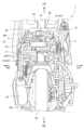
- FIG. 3 is a partial sectional view taken along the crankshaft of the internal combustion engine of the power unit.
- FIG. 2 is an overall right side view of the motorcycle shown in FIG. 1.
- FIG. 3 is a partially cutaway view of the fan cover in FIG. 2.
- FIG. It is a perspective view of a fan cover.
- FIG. 3 is a perspective view showing the vicinity of a notch portion of the fan cover.
- the straddle-type vehicle according to this embodiment is a scooter type motorcycle 1, and a right side view of the motorcycle 1 is shown in FIG.
- the front, rear, left, right, and up and down directions are based on the usual standard in which the straight traveling direction of the motorcycle 1 according to the present embodiment is the forward direction, and in the drawings, FR refers to the front, and RE refers to the forward direction.
- LH indicates left, RH indicates right, UP indicates upward, and DW indicates downward.
- the front part 1F of the vehicle body and the rear part 1R of the vehicle body are connected via a low floor part 1C, and the body frame F, which forms the skeleton of the vehicle body, is generally connected to a down tube 3 and a main pipe 4.
- a down tube 3 extends downward from the head pipe 2 at the front part 1F of the vehicle body, and the down tube 3 is bent horizontally at the lower end and extends rearward under the floor part 1C, and at the rear end, a pair of left and right main pipes 4 are provided. are connected, and the main pipe 4 forms an inclined part 4a extending diagonally upward rearward from the connecting part, and the upper part of the inclined part 4a is further bent to form a horizontal part 4b extending rearward substantially horizontally. .
- the vertically oriented parts of the head pipe 2 and down tube 3 are covered from the front and back by the front cover 1a and the leg shield 1b, and in the floor part 1C, the longitudinally oriented part of the down tube 3 is covered by the lower side cover 1c.
- the main pipe 4 is covered on the left, right, and rear sides by the body cover 1d.
- the lower side cover 1c that covers the lower part of the vehicle extends from the lower part of the front cover 1a toward the rear of the vehicle and covers a portion of the right side of the power unit P, as shown in FIGS. 2 and 7.
- a storage box 5 and a fuel tank (not shown) are supported front and rear between the pair of main pipes 4, and a sheet 7 is disposed to cover the storage box 5 and the fuel tank.
- a handle 8 is provided above and supported pivotally by the head pipe 2, and a front fork 9 extends downward, and a front wheel 10 is pivotally supported at the lower end of the front fork 9.
- a support bracket 11 is provided to protrude rearward at approximately half of the inclined portion 4a of the main pipe 4 in the longitudinal direction.
- a hanger 22h is provided on the upper part of the power unit P to protrude obliquely upward.
- the support bracket 11 of the main pipe 4 and the hanger 22h are connected via a link member 12, and the power unit P is swingably connected and supported to the main pipe 4 by these link mechanisms.
- a power unit P has a single-cylinder, four-stroke, air-cooled internal combustion engine 20 stacked one on top of the other in its front part, starting from a crankcase 22 that supports a crankshaft 21 oriented in the vehicle width direction.
- the cylinder block 23, cylinder head 24, and head cover 25 are provided so as to protrude forward in a substantially horizontally tilted position.
- crankcase 22 is divided into left and right parts, and consists of a left crankcase part 22L and a right crankcase part 22R. 22R are rotatably supported via main bearings 21b and 21b, respectively.
- An AC generator 55 is provided on the right shaft portion of the crankshaft 21, and a centrifugal cooling fan 56 is integrally attached to an outer rotor 55r of the AC generator 55.
- a fan cover 57 that covers the right crankcase portion 22R from the right side accommodates a centrifugal cooling fan 56 therein. Referring also to FIG. 2, the fan cover 57 is formed with a grill 57g that is an outside air inlet facing the centrifugal cooling fan 56.
- the left crankcase portion 22L extends rearward and also serves as a transmission case portion, and a transmission case cover 65 covers the transmission case portion (left crankcase portion) 22L from the left side.
- a belt type continuously variable transmission 60 as a transmission is provided.
- a drive chain sprocket 58 is provided on the left shaft portion of the crankshaft 21 adjacent to the main bearing 21b, and a drive pulley 61 of a belt type continuously variable transmission 60 is provided on the left shaft end portion.
- a cam chain 59 wrapped around a drive chain sprocket 58 transmits power to the valve mechanism on the cylinder head 24 side.
- the reduction gear output shaft of the reduction mechanism 64 provided at the rear of the belt type continuously variable transmission 60 is a rear axle 28a, and the rear wheel 28 is provided on the rear axle 28a.
- a rear cushion (not shown) is interposed between the upper end of the rear portion of the transmission case portion 22L that accommodates the speed reduction mechanism 64 and the upper bent portion of the main pipe 4.
- a driven pulley 63 of a belt type continuously variable transmission 60 is pivotally supported on a reducer input shaft 64a of a reduction mechanism 64, and a drive pulley 61 provided on the crankshaft 21 and a reducer input shaft 64a of a reduction mechanism 64 are supported.
- a belt 62 is wound around a driven pulley 63 provided on the shaft 64a, and the power of the internal combustion engine 20 is transmitted to the driven pulley 63 via the belt 62, and the rotation of the driven pulley 63 is controlled via a centrifugal clutch (not shown).
- the power is transmitted to the speed reducer input shaft 64a of the speed reduction mechanism 64, the speed is reduced by the speed reduction mechanism 64, and the power is transmitted to the rear wheels 28.
- an outside air suction fan 61F is formed on the left half of the drive pulley 61.
- a shroud 70 as shown in FIG. 6 surrounds the cylinder block 23 and cylinder head 24, and the shroud 70 is connected to the fan cover 57 on the right side.
- an intake port 24a is formed on the upper surface side of the cylinder head 24 of the internal combustion engine 20 at the front of the power unit P, and an inlet pipe 31 as an intake pipe extends upward from the intake port 24a.
- An exhaust port 24b is formed on the lower surface side of the cylinder head 24, and an exhaust pipe 51 extends downward from the exhaust port 24b.
- an ignition plug 26 is fitted into the cylinder head 24 near the center head cover 25, and an oxygen concentration sensor 27 is fitted into the cylinder head 24 at a location where the exhaust pipe 51 extends.
- An intake device 30 that takes in outside air and sends it to the internal combustion engine 20 is connected to the intake port 24a of the internal combustion engine 20.
- the inside of the intake device 30 is an intake passage through which intake air sent to the internal combustion engine 20 introduces the intake air into the combustion chamber 20a of the internal combustion engine 20.
- the intake device 30 includes an air cleaner device 40 that takes in outside air and purifies it, a connecting tube 36 connected to the air cleaner device 40, a throttle body 33 connected to the downstream side of the connecting tube 36, and a An inlet pipe 31 to be connected is provided, and these constitute an intake system.
- an air cleaner case 41 in which left and right unpurified chamber cases 42 and purified chamber cases 43 are combined is located between the unpurified chamber case 42 and the purified chamber case 43.
- the air cleaner element 44 is partitioned into an unpurified chamber Ca on the unpurified chamber case 42 side and a purified chamber Cb on the purified chamber case 43 side by a partition portion 45 in which the air cleaner element 44 is disposed.
- an air introduction pipe 47 through which running wind and the like are taken in is arranged such that its opening 47a faces forward.
- the intake air introduced from the opening 47a passes through the air cleaner element 44 from within the unpurified chamber Ca, is purified, and is sent to the purified chamber Cb.
- the purification chamber Cb of the air cleaner device 40 is communicated with the throttle body 33 through an elastically deformable connecting tube 36 made of rubber.
- a fuel injection valve 37 is attached from the upper surface of each of the throttle body 33 and the inlet pipe 31, and fuel is injected into the intake passage.
- an exhaust device 50 is connected to the exhaust port 24b of the cylinder head 24.
- the exhaust system 50 includes an exhaust pipe 51 connected to the exhaust port 24b, a muffler 52 connected to the rear end of the exhaust pipe 51 with an atmosphere opening 52a facing toward the rear of the vehicle, and a built-in part in the middle of the exhaust pipe 51.
- a catalyst device 53 is provided. Exhaust gas discharged from the internal combustion engine 20 flows into the exhaust pipe 51 from the exhaust port 24b, is purified by the catalyst device 53 provided in the middle of the exhaust pipe 51, passes through the muffler 52, and is released into the atmosphere from the atmosphere opening 52a. is discharged inside.
- the exhaust pipe 51 communicates with the exhaust port 24b, extends downward from the lower surface of the cylinder head 24, bends diagonally forward to the left, further bends from the rear to the right, and extends from the left side of the lower part of the crankcase 22 to the right side. It is bent, extends rearward, and is connected to a muffler 52 disposed on the right side of the rear wheel 28.
- the exhaust pipe 51 includes a catalyst device housing exhaust pipe 51c in which a catalyst device 53 is built-in, an upstream exhaust pipe 51a connected to the upstream side of the catalyst device housing exhaust pipe 51c, and a downstream side exhaust pipe 51c of the catalyst device housing exhaust pipe 51c. and a downstream exhaust pipe 51b connected to the side.
- the upstream exhaust pipe 51a communicates with the exhaust port 24b, extends downward from the lower surface of the cylinder head 24 (see also FIG. 3), then bends diagonally forward to the left, and then bends from the rear to the right to connect the catalyst. It is connected to the device housing exhaust pipe 51c.
- the catalyst device housing exhaust pipe 51c is located below the internal combustion engine 20, and is arranged so that exhaust gas flows from the right side to the left side of the vehicle, oriented in the vehicle width direction.
- the catalyst device housing exhaust pipe 51c is arranged such that its upstream end is located on the left side in the vehicle width direction, and its downstream end is located on the right side in the vehicle width direction.
- the upstream end is connected to an upstream exhaust pipe 51a, and the downstream end is connected to a downstream exhaust pipe 51b.
- a catalyst device 53 is housed inside the catalyst device housing exhaust pipe 51c so that its axial direction faces in the vehicle width direction.
- the catalyst device 53 is a honeycomb-like porous structure having a large number of pores extending in the axial direction, and supports components for decomposing exhaust gas, such as platinum, rhodium, and palladium.
- the downstream exhaust pipe 51b is connected to the downstream side of the catalyst device housing exhaust pipe 51c, extends in the vehicle width direction, and then curves toward the rear.
- the downstream exhaust pipe 51b extends rearward along the longitudinal direction of the vehicle on the outside in the vehicle width direction from the crankcase 22 forming the unit case Pc when viewed from the bottom of the vehicle.
- the downstream exhaust pipe 51b extends rearward from the left side of the lower part of the power unit P as seen from the right side of the vehicle body, and then is bent diagonally upward and extends rearward. It is connected to a muffler 52 arranged on the right side of the wheel 28.
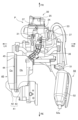
- FIG. 8 is a right side view of the main part near the power unit P, with a part of the front side of the fan cover 57 cut away.
- the downstream exhaust pipe 51b has two curved portions 51d, one on the upstream side and the other on the downstream side, in a side view.
- the downstream exhaust pipe is arranged such that the upstream curved part 51d 1 of the curved parts 51d, which is closest to the catalyst device housing exhaust pipe 51c, is located forward of the rotation center C1 of the cooling fan in the longitudinal direction of the vehicle when viewed from the side of the vehicle. 51b is formed.
- the saddle type vehicle of this embodiment has two curved portions 51d, it is only necessary to have at least one curved portion 51d, and it may have two or more curved portions 51d. It's okay.
- An exhaust gas sensor 54 is attached to the downstream exhaust pipe 51b, and detects the oxygen concentration in the exhaust gas that has passed through the catalyst device 53.
- the exhaust gas sensor 54 may be either an LAF sensor or an O2 sensor.
- the fan that forms part of the unit case Pc is located near the downstream exhaust pipe 51b and the exhaust gas sensor 54 and covers the right side of the centrifugal cooling fan 56.
- a cover 57 is provided.
- the fan cover 57 is integrally connected to a shroud 70 that covers a portion of the internal combustion engine 20 and covers the right side of the internal combustion engine 20.
- FIG. 9 shows a perspective view of the fan cover 57.
- the fan cover 57 includes a side wall portion 57a that covers the right side of the fan cover.
- a grill 57g is formed on the side wall portion 57a in a circular shape centered around the rotation center C1 of the centrifugal cooling fan 56 (see FIG. 6), and as the centrifugal cooling fan 56 rotates, outside air passes through the grill 57g. It is taken into the power unit P.
- a peripheral wall portion 57b is erected from the side wall portion 57a toward the internal combustion engine 20 at the upper and rear portions of the peripheral edge of the side wall portion 57a.
- the front edges of the side wall portion 57a and the peripheral wall portion 57b form a shroud joint edge 57c that is joined to the shroud 70.
- An eaves portion 57d is formed at the lower part of the side wall portion 57a, extending along the downstream exhaust pipe 51b and covering approximately the upper half of the downstream exhaust pipe 51b. Further, as shown in FIG. 2, the eaves portion 57d is formed to be longer in the longitudinal direction of the vehicle than the width of the side wall portion 57a in the longitudinal direction. The eaves portion 57d is formed such that its front end extends to cover the upstream curved portion 51d1 of the downstream exhaust pipe 51b, and its rear end extends to the vicinity of the rear curved portion 51d of the downstream exhaust pipe 51b. There is.
- the eaves portion 57d includes an extending portion 57d1 extending outward in the vehicle width direction from the side wall portion 57a, and a curved portion extending downward from the extending portion 57d1 .
- a side wall portion 57d 3 is formed to extend downward from the curved portion 57d 2 and cover the right side surface of the downstream exhaust pipe 51b.
- the extending portion 57d1 is formed such that its rear end edge becomes wider toward the rear of the vehicle.
- the curved portion 57d2 and the side wall portion 57d3 extend so that their rear edges become wider toward the rear of the vehicle, and the downstream end of the side wall portion 57d3 is connected to the downstream exhaust It extends to the vicinity of the curved portion 51d at the rear of the pipe 51b.
- the front portion of the side wall portion 57d3 is curved inward in the vehicle width direction along the downstream exhaust pipe 51b.
- a notch 57e that opens forward in the longitudinal direction of the vehicle is formed at the front edge of the extending portion 57d 1 and the curved portion 57d 2 of the eaves portion 57d.
- the notch 57e is formed to avoid the exhaust gas sensor 54 attached to the downstream exhaust pipe 51b, and as shown in FIGS. , the notch 57e and the exhaust gas sensor 54 overlap.
- the notch 57e is provided with an inclined portion 57f that is obliquely inclined toward the back so that the opening gradually widens. This prevents the exhaust gas sensor 54 from hitting the fan cover 57 and making it difficult to remove when the fan cover 57 is removed from the vehicle. Since the exhaust gas sensor 54 becomes hot, the fan cover 57 is disposed at a distance of about 10 mm from the exhaust gas sensor 54.
- FIG. 8 is a partially cutaway view of the eaves portion 57d of the fan cover 57 so that the exhaust gas sensor 54 attached to the downstream exhaust pipe 51b can be seen.
- the exhaust gas sensor 54 is attached to the downstream exhaust pipe 51b so as to be inserted downward from its upper surface.
- the exhaust gas sensor 54 is located in front and below the rotation center C1 of the centrifugal cooling fan 56 when viewed from the side of the vehicle, and as shown in FIG. are arranged so that they overlap.
- the exhaust gas sensor 54 partially overlaps with the lower side cover 1c when viewed from the side of the vehicle, thereby preventing it from being hit by flying stones, etc. from the side of the vehicle.
- the exhaust gas sensor 54 is connected to an imaginary line L1 connecting the rotation center C1 of the centrifugal cooling fan 56 and the upstream curved portion 51d1 when viewed from the side of the vehicle, and between the catalyst center point C2 and the rotation center of the catalyst device 53 when viewed from the side. It is attached to the upstream exhaust pipe 51a in an area surrounded by a line L2 connecting C1 and L3 connecting the catalyst center point C2 and the upstream curved portion 51d1 .
- the exhaust gas sensor 54 Since the exhaust gas sensor 54 is arranged as described above, the exhaust gas sensor 54 is placed close to the high-temperature catalyst device 53, and by early warming up and activating the exhaust gas sensor 54, the exhaust gas is reduced. The accuracy of sensor 54 can be increased.
- the power unit P is swingably supported at the upper part of the main pipe 4 of the body frame F via a link member 12.
- the lower part of the power unit P may be swingably supported by the vehicle body frame F via the link member 12.
- the power unit is swingably supported by the vehicle body frame F at its upper part.
- the motorcycle 1 of this embodiment includes a power unit P including an internal combustion engine 20 and a belt-type continuously variable transmission 60, a centrifugal cooling fan 56 that blows outside air into the power unit P, and a muffler connected to the power unit P.
- This is a straddle-type vehicle equipped with an exhaust pipe 51 that discharges exhaust gas from an atmosphere opening port 52a of 52, and a catalyst device 53 that purifies the exhaust gas.
- the downstream exhaust pipe 51b which has a side exhaust pipe 51a and a downstream exhaust pipe 51b on the downstream side of the catalyst device 53 and extends toward the rear of the vehicle, has at least a part of it from the unit case Pc when viewed from the bottom of the vehicle.
- the unit case Pc has a fan cover 57 that covers the centrifugal cooling fan 56 in the vehicle width direction, and when viewed from the side of the vehicle, the exhaust gas sensor 54 and the fan cover 57 are disposed on the outside in the vehicle width direction. They are arranged so that at least some of them overlap.
- the exhaust gas sensor 54 disposed in the downstream exhaust pipe 51b near the internal combustion engine 20, it is easy to warm up early using the heat of the internal combustion engine 20, and the exhaust gas sensor 54 can be accurately detected. be able to. Further, by disposing the exhaust gas sensor 54 provided in the downstream exhaust pipe 51b at a position immediately after the catalyst device 53 on the upstream side of the exhaust flow of the downstream exhaust pipe 51b, the exhaust gas sensor 54 and the muffler 52 are Since the distance of the atmosphere opening port 52a becomes longer, when the inside of the exhaust pipe 51 becomes negative pressure, the effect of turbulence of the exhaust gas in the pipe due to the outside air flowing in from the atmosphere opening port 52a is reduced, and the exhaust gas sensor 54 is Accuracy can be improved.
- the exhaust gas sensor 54 overlaps with the lower side cover 1c that covers the lower part of the vehicle when viewed from the side of the vehicle, so the side surface of the exhaust gas sensor 54 is covered by the lower side cover 1c, so that the exhaust gas sensor 54 is placed on the outside of the crankcase 22 in the vehicle width direction. Even if the exhaust gas sensor 54 is placed in the exhaust pipe 51 located in the exhaust pipe 51, it is possible to prevent the exhaust gas sensor 54 from being directly hit by the driving wind and prevent the exhaust gas sensor 54 from being cooled down rapidly, thereby preventing a decrease in detection accuracy. .
- the fan cover 57 has an eaves portion 57d that covers the downstream exhaust pipe 51b, it is possible to protect the occupants from the exhaust pipe 51 which is heated to a high temperature due to exhaust heat, and also to prevent the occupant's clothes from being heated. It is possible to prevent this from hitting the exhaust pipe 51.
- the eaves portion 57d of the fan cover 57 has a notch portion 57e that opens in the longitudinal direction of the vehicle, and since the notch portion 57e and the exhaust gas sensor 54 overlap when viewed from the side of the vehicle, the eaves portion of the fan cover 57
- the notch 57e By providing the notch 57e in 57d, it becomes possible to insert tools and the like when installing the exhaust gas sensor 54, improving ease of installation and maintenance.
- P...Power unit Pc...Unit case, C1...Rotation center, 1c...lower side cover, 20...Internal combustion engine, 51...Exhaust pipe, 51a...Upstream exhaust pipe, 51b...Downstream exhaust pipe, 52a...Atmospheric opening, 53...Catalyst device, 54...Exhaust gas sensor, 56...Centrifugal cooling fan, 57...Fan cover, 57d...Eave part, 57e...notch part, 60...Belt type continuously variable transmission.
Landscapes
- Engineering & Computer Science (AREA)
- Chemical & Material Sciences (AREA)
- Mechanical Engineering (AREA)
- Combustion & Propulsion (AREA)
- General Engineering & Computer Science (AREA)
- Chemical Kinetics & Catalysis (AREA)
- Health & Medical Sciences (AREA)
- Toxicology (AREA)
- Transportation (AREA)
- Exhaust Gas After Treatment (AREA)
Abstract
内燃機関20と変速装置60を備えたパワーユニットPと、ファン56と、大気開放口52aから排気を排出する排気管51と触媒装置53とを備え、触媒装置53よりも下流側であって車体後方に延びる下流側排気管51bは、少なくともその一部が車両下面視でパワーユニットPのユニットケースPcよりも車幅方向外側に配置され、下流側排気管51bに車両側面視においてファン56の回転中心C1の前下方に排気ガスセンサー54が配設され、ユニットケースPcは車幅方向に向けてファン56を覆うファンカバー57を有し、車両側面視において排気ガスセンサー54はファンカバー57と少なくとも一部が重なるように配置され、排気ガスセンサーの早期暖気を可能とし、管内の排気ガスの乱れを抑制して、排気ガスセンサーの精度を向上させる鞍乗型車両が開示されている。
Description
本発明は、内燃機関に接続された排気管上に排気ガスセンサーを配設した鞍乗型車両に関する。
従来、内燃機関に接続され排気管内を通過する排気ガスの酸素濃度を計測するために、排気管に排気ガスセンサーが設けられた鞍乗型車両がある。このような鞍乗型車両では、排気管に取り付けられた排気ガスセンサーに、ファンカバーやサイレンサーカバーといったカバー類によって、走行風が当たることを防ぎ排気ガスセンサーの温度の低下を防ぐともに、障害物が当たることを防いで排気ガスセンサーを保護している(特許文献1)。
しかしこのような鞍乗型車両では、触媒装置下流側に配置された排気ガスセンサーは、内燃機関から離れたマフラー近傍の排気管に取り付けられており、内燃機関の始動時等の排気ガスセンサーの温度が低い状態において、早期暖気がし難いといった課題がある。さらに、排気ガスセンサーが、マフラー近傍の排気管に取り付けられることにより、マフラーの大気開放口から流入する外気によって、管内の排気ガスの流れが乱されることの影響を受けるといった課題がある。
本発明は、上記課題に鑑みなされたものであり、内燃機関と変速装置を備えたパワーユニットと、前記パワーユニット内に外気を送風するファンと、前記パワーユニットに接続されて大気開放口から排気を排出する排気管と、排気を浄化する触媒装置と、を備えた鞍乗型車両において、
前記排気管は、前記触媒装置よりも上流側の上流側排気管と、前記触媒装置よりも下流側の下流側排気管とを有し、
車体後方に延びる前記下流側排気管は、少なくともその一部が、車両下面視で、前記パワーユニットのユニットケースよりも車幅方向外側に配置され、
前記下流側排気管に、車両側面視において、前記ファンの回転中心の前下方に排気ガスセンサーが配設され、
前記ユニットケースは、車幅方向に向けて、前記ファンを覆うファンカバーを有し、
車両側面視において、前記排気ガスセンサーは、前記ファンカバーと少なくとも一部が重なるように配置されることを特徴とする鞍乗型車両である。
前記排気管は、前記触媒装置よりも上流側の上流側排気管と、前記触媒装置よりも下流側の下流側排気管とを有し、
車体後方に延びる前記下流側排気管は、少なくともその一部が、車両下面視で、前記パワーユニットのユニットケースよりも車幅方向外側に配置され、
前記下流側排気管に、車両側面視において、前記ファンの回転中心の前下方に排気ガスセンサーが配設され、
前記ユニットケースは、車幅方向に向けて、前記ファンを覆うファンカバーを有し、
車両側面視において、前記排気ガスセンサーは、前記ファンカバーと少なくとも一部が重なるように配置されることを特徴とする鞍乗型車両である。
前記構成によれば、下流側排気管に配設した排気ガスセンサーを、内燃機関の近傍に配置することで、内燃機関の熱を利用した早期暖気がし易く、精度良く検出することができる。また、下流側排気管に設けられた排気ガスセンサーを、下流側排気管の排気流れの上流側の触媒装置直後の位置に配設することで、排気ガスセンサーとマフラーの大気開放口の距離が長くなるので、排気管内が負圧となった際に、大気開放口から流入する外気による管内の排気ガスの乱れの影響を低減し、排気ガスセンサーの精度を向上させることができる。
また本発明は、前記排気ガスセンサーは、車両側面視で、車両の下方を覆うロアサイドカバーと重なることを特徴とする。
前記構成によれば、ロアサイドカバーによって排気ガスセンサーの側面が覆われることにより、クランクケースの車幅方向外側に位置する排気管に排気ガスセンサーを配置した場合でも、排気ガスセンサーに走行風が直接当たることを防ぎ、急激に排気ガスセンサーが冷却されることによる検出精度の低下を防止できる。
さらに本発明は、前記ファンカバーは、前記下流側排気管を覆う庇部を有していることを特徴とする。
前記構成によれば、排熱による高温に熱せられた排気管から乗員を守ることができるとともに、乗員の着衣等が熱せられた排気管に当たることを防ぐことができる。
さらにまた本発明は、前記ファンカバーの前記庇部は、車両前後方向に開口する切欠き部を有し、
車両側面視において、前記切欠き部と排気ガスセンサーが重なることを特徴とする。
車両側面視において、前記切欠き部と排気ガスセンサーが重なることを特徴とする。
前記構成によれば、ファンカバーの庇部に切欠き部を設けることで、排気ガスセンサーの取付け時等において工具等を入れることが可能となり、取付け性やメンテナンス性が向上する。
本発明によれば、下流側排気管に配設した排気ガスセンサーを、内燃機関の近傍に配置することで、内燃機関の熱を利用した早期暖気がし易く、精度良く検出することができる。また、下流側排気管に設けられた排気ガスセンサーを、下流側排気管の排気流れの上流側の触媒装置直後の位置に配設することで、排気ガスセンサーとマフラーの大気開放口の距離が長くなるので、排気管内が負圧となった際に、大気開放口から流入する外気による管内の排気ガスの乱れの影響を低減し、排気ガスセンサーの精度を向上させることができる。
以下、本発明に係る一実施の形態の鞍乗型車両について、図1ないし図10に基づいて説明する。
本実施の形態に係る鞍乗型車両はスクータ型の自動二輪車1であって、該自動二輪車1の右側面図を図1に示す。
なお、本明細書の説明において、前後左右および上下の向きは、本実施の形態に係る自動二輪車1の直進方向を前方とする通常の基準に従うものとし、図面において、FRは前方を,REは後方を、LHは左方を,RHは右方を、UPは上方を、DWは下方を示すものとする。
本実施の形態に係る鞍乗型車両はスクータ型の自動二輪車1であって、該自動二輪車1の右側面図を図1に示す。
なお、本明細書の説明において、前後左右および上下の向きは、本実施の形態に係る自動二輪車1の直進方向を前方とする通常の基準に従うものとし、図面において、FRは前方を,REは後方を、LHは左方を,RHは右方を、UPは上方を、DWは下方を示すものとする。
図1に示されるように、車体前部1Fと車体後部1Rとが、低いフロア部1Cを介して連結されており、車体の骨格をなす車体フレームFは、概ねダウンチューブ3とメインパイプ4とからなる。
すなわち車体前部1Fのヘッドパイプ2からダウンチューブ3が下方へ延出し、同ダウンチューブ3は下端で水平に屈曲してフロア部1Cの下方を後方へ延び、その後端において左右一対のメインパイプ4が連結され、メインパイプ4は該連結部から後方斜め上に延びた傾斜部4aを形成し、傾斜部4aの上部がさらに屈曲して後方に略水平に延びた水平部4bを形成している。
すなわち車体前部1Fのヘッドパイプ2からダウンチューブ3が下方へ延出し、同ダウンチューブ3は下端で水平に屈曲してフロア部1Cの下方を後方へ延び、その後端において左右一対のメインパイプ4が連結され、メインパイプ4は該連結部から後方斜め上に延びた傾斜部4aを形成し、傾斜部4aの上部がさらに屈曲して後方に略水平に延びた水平部4bを形成している。
車体前部1Fでは、ヘッドパイプ2およびダウンチューブ3の上下指向部がフロントカバー1aとレッグシールド1bにより前後から覆われ、フロア部1Cは、ダウンチューブ3の前後指向部がロアサイドカバー1cにより覆われ、車体後部1Rは、メインパイプ4がボデイカバー1dにより左右および後方が覆われる。車両の下方を覆うロアサイドカバー1cは、図2および図7に示されるように、フロントカバー1aの下部から車両後方に延伸して、パワーユニットPの右側の一部を覆っている。
一対のメインパイプ4の間には前後に収納ボックス5と燃料タンク(不図示)が支持され、収納ボックス5と燃料タンクの上方はシート7が覆って配置されている。
一方車体前部1Fにおいては、ヘッドパイプ2に軸支されて上方にハンドル8が設けられ、下方にフロントフォーク9が延びてその下端に前輪10が軸支されている。
一方車体前部1Fにおいては、ヘッドパイプ2に軸支されて上方にハンドル8が設けられ、下方にフロントフォーク9が延びてその下端に前輪10が軸支されている。
メインパイプ4の傾斜部4aの長手方向における略半分に位して、支持ブラケット11が後方に向けて突設されている。図2に示されるように、パワーユニットPの上部には、ハンガー22hが、斜め上方に向かって突設されている。メインパイプ4の支持ブラケット11とハンガー22hはリンク部材12を介して連結されており、これらのリンク機構により、パワーユニットPはメインパイプ4に揺動可能に連結支持される。
図3を参照して、パワーユニットPには、その前部に単気筒4ストローク空冷式の内燃機関20が、クランク軸21を車幅方向に指向させて軸支するクランクケース22から順次重ね合わされたシリンダブロック23,シリンダヘッド24,ヘッドカバー25を略水平に近い状態にまで大きく前傾した姿勢で前方に突出させて設けられている。
図6を参照して、クランクケース22は、左右割りで、左クランクケース部22Lと右クランクケース部22Rからなり、車幅方向に指向したクランク軸21を左クランクケース部22Lと右クランクケース部22Rがそれぞれ主軸受21b,21bを介して回転自在に軸支している。
クランク軸21の右側軸部にACジュエネレータ55が設けられ、ACジュエネレータ55のアウタローター55rに遠心冷却ファン56が一体に取り付けられている。
右クランクケース部22Rを右側から覆うファンカバー57が、遠心冷却ファン56を内部に収容する。図2も参照して、ファンカバー57には、遠心冷却ファン56に対向して外気導入口であるグリル57gが形成されている。
右クランクケース部22Rを右側から覆うファンカバー57が、遠心冷却ファン56を内部に収容する。図2も参照して、ファンカバー57には、遠心冷却ファン56に対向して外気導入口であるグリル57gが形成されている。
図6に示されるように、左クランクケース部22Lは、後方に延出して伝動ケース部を兼ね、同伝動ケース部(左クランクケース部)22Lを左側から伝動ケースカバー65が覆い、内部には変速装置としてのベルト式無段変速機60が配設される。クランク軸21の左側軸部には、主軸受21bに隣接して駆動チェーンスプロケット58が設けられ、左側軸端部には、ベルト式無段変速機60の駆動プーリ61が設けられている。
駆動チェーンスプロケット58に巻き掛けられるカムチェーン59によりシリンダヘッド24側の動弁機構に動力が伝達される。
図1および図3を参照して、ベルト式無段変速機60の後部に設けられた減速機構64の減速機出力軸が後車軸28aであり、後車軸28aに後輪28が設けられている。
伝動ケース部22Lの減速機構64を収容する後部の上端と前記メインパイプ4の上部屈曲部間にリヤクッション(不図示)が介装されている。
図1および図3を参照して、ベルト式無段変速機60の後部に設けられた減速機構64の減速機出力軸が後車軸28aであり、後車軸28aに後輪28が設けられている。
伝動ケース部22Lの減速機構64を収容する後部の上端と前記メインパイプ4の上部屈曲部間にリヤクッション(不図示)が介装されている。
図3に示されるように、減速機構64の減速機入力軸64aに、ベルト式無段変速機60の被動プーリ63が軸支されており、クランク軸21に設けられる駆動プーリ61と減速機入力軸64aに設けられる被動プーリ63とにベルト62が巻き掛けられて、内燃機関20の動力がベルト62を介して被動プーリ63に伝達され、被動プーリ63の回転は遠心クラッチ(不図示)を介して減速機構64の減速機入力軸64aに伝達され、減速機構64で減速されて後輪28に動力伝達される。図6に示されるように、駆動プーリ61の左側のプーリ半体には外気吸入ファン61Fが形成されている。
シリンダブロック23およびシリンダヘッド24の周囲を、図6に示されるようなシュラウド70が囲繞し、シュラウド70は右側においてファンカバー57に連結される。
図3を参照して、パワーユニットPの前部の内燃機関20のシリンダヘッド24の上面側に吸気ポート24aが形成され、該吸気ポート24aから吸気管としてのインレットパイプ31が上方に延出している。シリンダヘッド24の下面側に排気ポート24bが形成され、該排気ポート24bから排気管51が下方に延出する。
また、シリンダヘッド24には、点火プラグ26が中央のヘッドカバー25寄りに嵌挿されるとともに、排気管51が延出する箇所に酸素濃度センサー27が嵌挿されている。
また、シリンダヘッド24には、点火プラグ26が中央のヘッドカバー25寄りに嵌挿されるとともに、排気管51が延出する箇所に酸素濃度センサー27が嵌挿されている。
内燃機関20の吸気ポート24aには、外気を吸入して内燃機関20に送る吸気装置30が接続されている。吸気装置30内は、内燃機関20の燃焼室20aに吸気を導入する内燃機関20に送られる吸気が通過する吸気通路となっている。
吸気装置30は、外気を取入れて浄化するエアクリーナ装置40と、エアクリーナ装置40に連結されるコネクティングチューブ36と、コネクティングチューブ36の下流側に連結されるスロットルボディ33と、スロットルボディ33の上流側に接続されるインレットパイプ31と、を備えており、これらにより吸気系が構成される。
吸気装置30は、外気を取入れて浄化するエアクリーナ装置40と、エアクリーナ装置40に連結されるコネクティングチューブ36と、コネクティングチューブ36の下流側に連結されるスロットルボディ33と、スロットルボディ33の上流側に接続されるインレットパイプ31と、を備えており、これらにより吸気系が構成される。
図4に示されるように、吸気装置30のエアクリーナ装置40は、左右の未浄化室ケース42と浄化室ケース43が合体したエアクリーナケース41が、未浄化室ケース42と浄化室ケース43の間に配設されエアクリーナエレメント44が配設されている仕切部45により、エアクリーナエレメント44が未浄化室ケース42側の未浄化室Caと浄化室ケース43側の浄化室Cbとに仕切られている。
図3に示されるように未浄化室ケース42には、走行風などが取り込まれる空気導入管47が、その開口部47aが前方を向くように配設されている。開口部47aから導入された吸気は、未浄化室Ca内からエアクリーナエレメント44を通過して浄化され、浄化室Cbに送られる。エアクリーナ装置40の浄化室Cbは、ゴム製の弾性変形可能なコネクティングチューブ36により、スロットルボディ33と連通されている。燃料噴射弁37が、スロットルボディ33およびインレットパイプ31のそれぞれの上面から取り付けられ、吸気通路内に燃料が噴射される。
図3に示されるように未浄化室ケース42には、走行風などが取り込まれる空気導入管47が、その開口部47aが前方を向くように配設されている。開口部47aから導入された吸気は、未浄化室Ca内からエアクリーナエレメント44を通過して浄化され、浄化室Cbに送られる。エアクリーナ装置40の浄化室Cbは、ゴム製の弾性変形可能なコネクティングチューブ36により、スロットルボディ33と連通されている。燃料噴射弁37が、スロットルボディ33およびインレットパイプ31のそれぞれの上面から取り付けられ、吸気通路内に燃料が噴射される。
図5に示されるように、シリンダヘッド24の排気ポート24bには、排気装置50が接続されている。排気装置50は、排気ポート24bに接続される排気管51と、排気管51の後端に接続され大気開放口52aを車両後向に向けたマフラー52と、排気管51の途中に内蔵される触媒装置53を備えている。
内燃機関20から排出される排気ガスは、排気ポート24bから排気管51に流入し、排気管51の途中に設けられた触媒装置53で浄化され、マフラー52を通過し、大気開放口52aより大気中に排出される。
内燃機関20から排出される排気ガスは、排気ポート24bから排気管51に流入し、排気管51の途中に設けられた触媒装置53で浄化され、マフラー52を通過し、大気開放口52aより大気中に排出される。
排気管51は、排気ポート24bに連通してシリンダヘッド24の下面から下方に延出し、左側斜前方に屈曲し、さらに後方から右方へ屈曲して、クランクケース22の下部の左側から右側へ屈曲し、後方へ延びて後輪28の右側に配設されるマフラー52に連結されている。
排気管51は、途中に触媒装置53が内蔵される触媒装置収容排気管51cと、触媒装置収容排気管51cの上流側に接続される上流側排気管51aと、触媒装置収容排気管51cの下流側に接続される下流側排気管51bとから構成されている。
上流側排気管51aは、排気ポート24bに連通してシリンダヘッド24の下面から下方に延出し(図3も参照)、その後左側斜前方に屈曲してさらに後方から右方へに屈曲して触媒装置収容排気管51cに接続される。
触媒装置収容排気管51cは、内燃機関20の下方に位置し、車幅方向に指向して車両の右側から左側に向かって排気が流れるように配設されている。
触媒装置収容排気管51cは、上流端が車幅方向における左側に位置し、下流端が車幅方向における右側に位置するように配設されている。上流端には上流側排気管51aに接続され、下流端には下流側排気管51bが接続されている。
触媒装置収容排気管51cは、上流端が車幅方向における左側に位置し、下流端が車幅方向における右側に位置するように配設されている。上流端には上流側排気管51aに接続され、下流端には下流側排気管51bが接続されている。
触媒装置収容排気管51cの内部には、その軸線方向が車幅方向に向かうように触媒装置53が収容されている。触媒装置53は、その軸線方向に向かって伸びる多数の細孔を有するハニカム状の多孔構造体であり、排気ガスを分解する成分として、例えば、白金、ロジウムおよびパラジウム等が担持されている。
下流側排気管51bは、図5に示されるように、触媒装置収容排気管51cの下流側に接続し、車幅方向に延びたのち、後方に向かって湾曲している。下流側排気管51bは、車両下面視において、ユニットケースPcを構成するクランクケース22より車幅方向における外側を車両前後方向に沿って後方に向かって延伸されている。さらに、下流側排気管51bは、図2および図7に示されるように、車体右側面視において、パワーユニットPの下部の左側から後方へ延びて、その後斜め上方に向かって屈曲されて延び、後輪28の右側に配設されるマフラー52に連結されている。
図8は、ファンカバー57の前側の一部を切り欠いた状態の、パワーユニットP近傍の要部右側面図である。下流側排気管51bは、側面視において、上流側と下流側との2つの湾曲部51dを有している。この湾曲部51dのうち触媒装置収容排気管51cに最も近い上流側湾曲部51d1が、車両側面視において、冷却ファンの回転中心C1より車両前後方向において前方に位置するように、下流側排気管51bは、形成されている。
本実施の形態の鞍乗型車両では、2つの湾曲部51dを有しているが、少なくとも1つの湾曲部51dを有していればよく、2つ以上の複数の湾曲部51dを有していてもよい。
本実施の形態の鞍乗型車両では、2つの湾曲部51dを有しているが、少なくとも1つの湾曲部51dを有していればよく、2つ以上の複数の湾曲部51dを有していてもよい。
下流側排気管51bには排気ガスセンサー54が取り付けられており、触媒装置53を通過した排気ガス中の酸素濃度を検出する。排気ガスセンサー54は、LAFセンサーやO2センサーのいずれであってもよい。
図2および図6に示されるように、下流側排気管51bおよび排気ガスセンサー54の近傍に位置して、遠心冷却ファン56の右側方を覆うように、ユニットケースPcの一部を構成するファンカバー57が配設されている。ファンカバー57は、内燃機関20の一部の周囲を覆うシュラウド70と一体に連結され、内燃機関20の右側方を覆っている。
ファンカバー57について詳細に述べる。図9に、ファンカバー57の斜視図を示す。ファンカバー57は、ファンカバーの右側方を覆う側壁部57aを備えている。側壁部57aには、グリル57gが遠心冷却ファン56の回転中心C1を中心点とする円形に形成されており(図6参照)、遠心冷却ファン56の回転により、外気がグリル57gを通過してパワーユニットP内に取り込まれる。
このような側壁部57aの周縁の上部および後部において、側壁部57aから内燃機関20側に向かって、周壁部57bが立設されている。側壁部57aと周壁部57bの前方の端縁は、シュラウド70と接合されるシュラウド接合縁部57cとなっている。
このような側壁部57aの周縁の上部および後部において、側壁部57aから内燃機関20側に向かって、周壁部57bが立設されている。側壁部57aと周壁部57bの前方の端縁は、シュラウド70と接合されるシュラウド接合縁部57cとなっている。
側壁部57aの下部には、下流側排気管51bに沿って下流側排気管51bの略上半分を覆う庇部57dが形成されている。さらに、庇部57dは、図2に示されるように、車両前後方向において、側壁部57a前後の幅よりも前後方向に延伸するように長く形成されている。庇部57dは、その前端が下流側排気管51bの上流側湾曲部51d1を覆うように延伸され、その後端は下流側排気管51bの後方の湾曲部51d近傍まで延伸するように形成されている。
図9を参照して、庇部57dは、側壁部57aから車幅方向外側に延出する延出部57d1と、延出部57d1から下方に向かうように湾曲した形状に延伸される湾曲部57d2と、湾曲部57d2から下方に延び下流側排気管51bの右側面を覆うように形成された側壁部57d3から構成されている。
延出部57d1は、後方端縁が車両後方に向かってその幅が広くなるように延伸して形成されている。図2も参照して、湾曲部57d2と側壁部57d3とは、後方端縁が車両後方に向かうに従ってその幅が広くなるように延伸して、側壁部57d3の下流端は下流側排気管51bの後方の湾曲部51d近傍まで延伸している。また、側壁部57d3の前部は、下流側排気管51bに沿うように車幅方向内側に向かって湾曲して形成されている。
図9に示されるように、庇部57dの延出部57d1および湾曲部57d2前方の端縁には、車両前後方向において前方に開口した切欠き部57eが形成されている。図10に示されるように、切欠き部57eは、下流側排気管51bに取り付けられた排気ガスセンサー54を避けるように形成されており、図2及び図9に示されるように、車両側面視において、切欠き部57eと排気ガスセンサー54とは重なる。
図9に示されるように、切欠き部57eは、開口部が徐々に広がるように奥側に向かって斜めに傾斜した傾斜部57fが設けられている。ファンカバー57を車両から取り外す際に、排気ガスセンサー54がファンカバー57に当たって取り外し難くなることを防いでいる。排気ガスセンサー54が高温になるため、ファンカバー57は、排気ガスセンサー54から10mm程度の間隔をあけるように配設されている。
図8は、下流側排気管51bに取り付けられた排気ガスセンサー54が見えるように、ファンカバー57の庇部57dの一部を切り欠いた図である。排気ガスセンサー54は、図8および図10に示されるように、下流側排気管51bには、その上面から下方に向かって差し込まれるように取り付けられている。排気ガスセンサー54は、図8に示されるように、車両側面視において、遠心冷却ファン56の回転中心C1の前下方に位置し、図2に示されるように、ファンカバー57と少なくともその一部が重なるように配設されている。
さらに、排気ガスセンサー54は、図7および図8に示されるように、車両側面視でロアサイドカバー1cとその一部が重なっており、車両側方からの飛び石等が当たることを防いでいる。
また、排気ガスセンサー54は、車両側面視において、遠心冷却ファン56の回転中心C1と上流側湾曲部51d1を結んだ仮想線L1と、触媒装置53の側面視における触媒中心点C2と回転中心C1とを結んだ線L2と、触媒中心点C2と上流側湾曲部51d1を結んだL3で囲まれた領域に、上流側排気管51aに取り付けられている。
また、排気ガスセンサー54は、車両側面視において、遠心冷却ファン56の回転中心C1と上流側湾曲部51d1を結んだ仮想線L1と、触媒装置53の側面視における触媒中心点C2と回転中心C1とを結んだ線L2と、触媒中心点C2と上流側湾曲部51d1を結んだL3で囲まれた領域に、上流側排気管51aに取り付けられている。
排気ガスセンサー54が上記したように配設されているので、排気ガスセンサー54が高温の触媒装置53に近づけて配置され、排気ガスセンサー54を早期に暖気して活性化することで、排気ガスセンサー54の精度を高めることができる。
さらに、排気ガスセンサー54は、図8に示されるように、マフラー52の大気開放口52aから離れた位置にあるために、排気管51内が負圧となった際に排気管内に流入する外気による排気ガスの乱れが、排気ガスセンサー54に影響を与えることが少ない。
また、図1示されるように、本実施の形態の自動二輪車1では、パワーユニットPはその上部において、車体フレームFのメインパイプ4にリンク部材12を介して揺動自在に支持されているが、パワーユニットPの下部において、リンク部材12を介して車体フレームFに揺動自在に支持されてもよい。一方、パワーユニットの組付け性の観点や、触媒装置と排気ガスセンサーをコンパクトに配置する観点から、パワーニットはその上部において車体フレームFに揺動自在に支持される方が、好ましい。
本発明の実施の形態の鞍乗型車両は、前記したように構成されているので、以下のような効果を奏する。
本実施の形態の自動二輪車1は、内燃機関20とベルト式無段変速機60を備えたパワーユニットPと、パワーユニットP内に外気を送風する遠心冷却ファン56と、パワーユニットPに接続されて、マフラー52の大気開放口52aから排気を排出する排気管51と、排気を浄化する触媒装置53と、を備えた鞍乗型車両であって、排気管51は、触媒装置53よりも上流側の上流側排気管51aと、触媒装置53よりも下流側の下流側排気管51bとを有し、車体後方に延びる下流側排気管51bは、少なくともその一部が、車両下面視で、ユニットケースPcよりも車幅方向外側に配置され、ユニットケースPcには、車幅方向に向けて、遠心冷却ファン56を覆うファンカバー57を有し、車両側面視において、排気ガスセンサー54は、ファンカバー57と少なくとも一部が重なるように配置される。
前記構成によれば、下流側排気管51bに配設した排気ガスセンサー54を、内燃機関20の近傍に配置することで、内燃機関20の熱を利用した早期暖気がし易く、精度良く検出することができる。また、下流側排気管51bに設けられた排気ガスセンサー54を、下流側排気管51bの排気流れの上流側の触媒装置53直後の位置に配設することで、排気ガスセンサー54とマフラー52の大気開放口52aの距離が長くなるので、排気管51内が負圧となった際に、大気開放口52aから流入する外気による管内の排気ガスの乱れの影響を低減し、排気ガスセンサー54の精度を向上させることができる。
また排気ガスセンサー54は、車両側面視で、車両の下方を覆うロアサイドカバー1cと重なるので、ロアサイドカバー1cによって排気ガスセンサー54の側面が覆われることにより、クランクケース22の車幅方向外側に位置する排気管51に排気ガスセンサー54を配置した場合でも、排気ガスセンサー54に走行風が直接当たることを防ぎ、急激に排気ガスセンサー54が冷却されることにより検出精度の低下を防止できる。
さらにファンカバー57は、下流側排気管51bを覆う庇部57dを有しているので、排熱による高温に熱せられた排気管51から乗員を守ることができるとともに、乗員の着衣等が熱せられた排気管51に当たることを防ぐことができる。
さらにまた、ファンカバー57の庇部57dは、車両前後方向に開口する切欠き部57eを有し、車両側面視において、切欠き部57eと排気ガスセンサー54が重なるので、ファンカバー57の庇部57dに切欠き部57eを設けることで、排気ガスセンサー54の取付け時等において工具等を入れることが可能となり、取付け性やメンテナンス性が向上する。
以上、本発明に係る一実施の形態に係る車載内燃機関の吸気構造について説明したが、本発明の態様は、上記実施の形態に限定されず、本発明の要旨の範囲で、多様な態様で実施されるものを含むものである。
P…パワーユニット、Pc…ユニットケース、C1…回転中心、
1c…ロアサイドカバー、
20…内燃機関、
51…排気管、51a…上流側排気管、51b…下流側排気管、52a…大気開放口、53…触媒装置、54…排気ガスセンサー、56…遠心冷却ファン、57…ファンカバー、57d…庇部、57e…切欠き部、
60…ベルト式無段変速機。
1c…ロアサイドカバー、
20…内燃機関、
51…排気管、51a…上流側排気管、51b…下流側排気管、52a…大気開放口、53…触媒装置、54…排気ガスセンサー、56…遠心冷却ファン、57…ファンカバー、57d…庇部、57e…切欠き部、
60…ベルト式無段変速機。
Claims (4)
- 内燃機関(20)と変速装置(60)を備えたパワーユニット(P)と、前記パワーユニット(P)内に外気を送風するファン(56)と、前記パワーユニット(P)に接続されて大気開放口(52a)から排気を排出する排気管(51)と、排気を浄化する触媒装置(53)と、を備えた鞍乗型車両において、
前記排気管(51)は、前記触媒装置(53)よりも上流側の上流側排気管(51a)と、前記触媒装置(53)よりも下流側の下流側排気管(51b)とを有し、
車体後方に延びる前記下流側排気管(51b)は、少なくともその一部が、車両下面視で、前記パワーユニット(P)のユニットケース(Pc)よりも車幅方向外側に配置され、
前記下流側排気管(51b)に、車両側面視において、前記ファン(56)の回転中心(C1)の前下方に排気ガスセンサー(54)が配設され、
前記ユニットケース(Pc)は、車幅方向に向けて前記ファン(56)を覆うファンカバー(57)を有し、
車両側面視において、前記排気ガスセンサー(54)は、前記ファンカバー(57)と少なくとも一部が重なるように配置されることを特徴とする鞍乗型車両。 - 前記排気ガスセンサー(54)は、車両側面視で、車両の下方を覆うロアサイドカバー(1c)と重なることを特徴とする請求項1に記載の鞍乗型車両。
- 前記ファンカバー(57)は、前記下流側排気管(51b)を覆う庇部(57d)を有していることを特徴とする請求項1または請求項2のいずれかに記載の鞍乗型車両。
- 前記ファンカバー(57)の前記庇部(57d)は、車両前後方向に開口する切欠き部(57e)を有し、
車両側面視において、前記切欠き部(57e)と排気ガスセンサー(54)が重なることを特徴とする請求項3に記載の鞍乗型車両。
Priority Applications (1)
| Application Number | Priority Date | Filing Date | Title |
|---|---|---|---|
| JP2024511702A JPWO2023189494A1 (ja) | 2022-03-31 | 2023-03-13 |
Applications Claiming Priority (2)
| Application Number | Priority Date | Filing Date | Title |
|---|---|---|---|
| JP2022-060509 | 2022-03-31 | ||
| JP2022060509 | 2022-03-31 |
Publications (1)
| Publication Number | Publication Date |
|---|---|
| WO2023189494A1 true WO2023189494A1 (ja) | 2023-10-05 |
Family
ID=88200911
Family Applications (1)
| Application Number | Title | Priority Date | Filing Date |
|---|---|---|---|
| PCT/JP2023/009664 WO2023189494A1 (ja) | 2022-03-31 | 2023-03-13 | 鞍乗型車両 |
Country Status (2)
| Country | Link |
|---|---|
| JP (1) | JPWO2023189494A1 (ja) |
| WO (1) | WO2023189494A1 (ja) |
Citations (6)
| Publication number | Priority date | Publication date | Assignee | Title |
|---|---|---|---|---|
| JPS58122677U (ja) * | 1982-02-15 | 1983-08-20 | 本田技研工業株式会社 | 車体カバ−内部の冷却装置 |
| JP2019138222A (ja) * | 2018-02-09 | 2019-08-22 | 本田技研工業株式会社 | 鞍乗型車両 |
| JP2019138227A (ja) * | 2018-02-09 | 2019-08-22 | 本田技研工業株式会社 | 内燃機関 |
| JP2019190354A (ja) * | 2018-04-24 | 2019-10-31 | ヤマハ発動機株式会社 | スクータ |
| EP3165730B1 (en) * | 2014-07-04 | 2020-04-29 | Yamaha Hatsudoki Kabushiki Kaisha | Vehicle and single-cylinder four-stroke engine unit |
| EP3524785B1 (en) * | 2018-02-09 | 2021-05-26 | Honda Motor Co., Ltd. | Saddle riding vehicle |
-
2023
- 2023-03-13 JP JP2024511702A patent/JPWO2023189494A1/ja active Pending
- 2023-03-13 WO PCT/JP2023/009664 patent/WO2023189494A1/ja active Search and Examination
Patent Citations (6)
| Publication number | Priority date | Publication date | Assignee | Title |
|---|---|---|---|---|
| JPS58122677U (ja) * | 1982-02-15 | 1983-08-20 | 本田技研工業株式会社 | 車体カバ−内部の冷却装置 |
| EP3165730B1 (en) * | 2014-07-04 | 2020-04-29 | Yamaha Hatsudoki Kabushiki Kaisha | Vehicle and single-cylinder four-stroke engine unit |
| JP2019138222A (ja) * | 2018-02-09 | 2019-08-22 | 本田技研工業株式会社 | 鞍乗型車両 |
| JP2019138227A (ja) * | 2018-02-09 | 2019-08-22 | 本田技研工業株式会社 | 内燃機関 |
| EP3524785B1 (en) * | 2018-02-09 | 2021-05-26 | Honda Motor Co., Ltd. | Saddle riding vehicle |
| JP2019190354A (ja) * | 2018-04-24 | 2019-10-31 | ヤマハ発動機株式会社 | スクータ |
Also Published As
| Publication number | Publication date |
|---|---|
| JPWO2023189494A1 (ja) | 2023-10-05 |
Similar Documents
| Publication | Publication Date | Title |
|---|---|---|
| TWI637106B (zh) | Straddle type vehicle | |
| TWI611098B (zh) | 車輛及單缸四衝程引擎單元 | |
| JP6208353B2 (ja) | ビークルおよび単気筒4ストロークエンジンユニット | |
| TWI611097B (zh) | 跨坐型車輛及單缸四衝程引擎單元 | |
| WO2016002962A1 (ja) | ビークルおよび単気筒4ストロークエンジンユニット | |
| TWI700429B (zh) | 跨坐型車輛及單缸四衝程引擎單元 | |
| EP1577208A2 (en) | Saddle riding type vehicle | |
| JP6658820B2 (ja) | 自動二輪車 | |
| JP6690440B2 (ja) | 排気ガスセンサの配置構造 | |
| WO2023189494A1 (ja) | 鞍乗型車両 | |
| WO2016002957A1 (ja) | 鞍乗型車両、及び、単気筒4ストロークエンジンユニット | |
| CN112567115B (zh) | 排气系统 | |
| WO2023189500A1 (ja) | 鞍乗型車両 | |
| JP3302047B2 (ja) | 自動二輪車の排気浄化装置 | |
| JP7433403B1 (ja) | 内燃機関及び鞍乗型車両 | |
| WO2024071032A1 (ja) | 鞍乗型車両 | |
| WO2023189504A1 (ja) | 鞍乗型車両 | |
| JP7275775B2 (ja) | 自動二輪車 | |
| JPH05332132A (ja) | 自動二輪車の排気浄化装置 | |
| JP3259982B2 (ja) | 自動二輪車の排気浄化装置 | |
| WO2023189962A1 (ja) | 鞍乗型車両 | |
| JP2024051818A (ja) | 内燃機関の排気装置、内燃機関及び鞍乗型車両 | |
| JP3283060B2 (ja) | 車両の排気浄化装置 | |
| JP7119734B2 (ja) | 自動二輪車 | |
| WO2023188279A1 (ja) | 内燃機関の吸気構造 |
Legal Events
| Date | Code | Title | Description |
|---|---|---|---|
| 121 | Ep: the epo has been informed by wipo that ep was designated in this application |
Ref document number: 23779514 Country of ref document: EP Kind code of ref document: A1 |
|
| DPE1 | Request for preliminary examination filed after expiration of 19th month from priority date (pct application filed from 20040101) | ||
| ENP | Entry into the national phase |
Ref document number: 2024511702 Country of ref document: JP Kind code of ref document: A |