WO2016002811A1 - 凝縮器及び洗浄装置 - Google Patents
凝縮器及び洗浄装置 Download PDFInfo
- Publication number
- WO2016002811A1 WO2016002811A1 PCT/JP2015/068903 JP2015068903W WO2016002811A1 WO 2016002811 A1 WO2016002811 A1 WO 2016002811A1 JP 2015068903 W JP2015068903 W JP 2015068903W WO 2016002811 A1 WO2016002811 A1 WO 2016002811A1
- Authority
- WO
- WIPO (PCT)
- Prior art keywords
- cleaning
- steam
- drying chamber
- chamber
- condenser
- Prior art date
Links
Images


Classifications
-
- D—TEXTILES; PAPER
- D06—TREATMENT OF TEXTILES OR THE LIKE; LAUNDERING; FLEXIBLE MATERIALS NOT OTHERWISE PROVIDED FOR
- D06F—LAUNDERING, DRYING, IRONING, PRESSING OR FOLDING TEXTILE ARTICLES
- D06F43/00—Dry-cleaning apparatus or methods using volatile solvents
- D06F43/08—Associated apparatus for handling and recovering the solvents
- D06F43/086—Recovering the solvent from the drying air current
- D06F43/088—Condensing arrangements
-
- B—PERFORMING OPERATIONS; TRANSPORTING
- B01—PHYSICAL OR CHEMICAL PROCESSES OR APPARATUS IN GENERAL
- B01D—SEPARATION
- B01D5/00—Condensation of vapours; Recovering volatile solvents by condensation
- B01D5/0003—Condensation of vapours; Recovering volatile solvents by condensation by using heat-exchange surfaces for indirect contact between gases or vapours and the cooling medium
- B01D5/0006—Coils or serpentines
-
- B—PERFORMING OPERATIONS; TRANSPORTING
- B08—CLEANING
- B08B—CLEANING IN GENERAL; PREVENTION OF FOULING IN GENERAL
- B08B3/00—Cleaning by methods involving the use or presence of liquid or steam
-
- C—CHEMISTRY; METALLURGY
- C23—COATING METALLIC MATERIAL; COATING MATERIAL WITH METALLIC MATERIAL; CHEMICAL SURFACE TREATMENT; DIFFUSION TREATMENT OF METALLIC MATERIAL; COATING BY VACUUM EVAPORATION, BY SPUTTERING, BY ION IMPLANTATION OR BY CHEMICAL VAPOUR DEPOSITION, IN GENERAL; INHIBITING CORROSION OF METALLIC MATERIAL OR INCRUSTATION IN GENERAL
- C23G—CLEANING OR DE-GREASING OF METALLIC MATERIAL BY CHEMICAL METHODS OTHER THAN ELECTROLYSIS
- C23G5/00—Cleaning or de-greasing metallic material by other methods; Apparatus for cleaning or de-greasing metallic material with organic solvents
-
- F—MECHANICAL ENGINEERING; LIGHTING; HEATING; WEAPONS; BLASTING
- F28—HEAT EXCHANGE IN GENERAL
- F28D—HEAT-EXCHANGE APPARATUS, NOT PROVIDED FOR IN ANOTHER SUBCLASS, IN WHICH THE HEAT-EXCHANGE MEDIA DO NOT COME INTO DIRECT CONTACT
- F28D1/00—Heat-exchange apparatus having stationary conduit assemblies for one heat-exchange medium only, the media being in contact with different sides of the conduit wall, in which the other heat-exchange medium is a large body of fluid, e.g. domestic or motor car radiators
- F28D1/02—Heat-exchange apparatus having stationary conduit assemblies for one heat-exchange medium only, the media being in contact with different sides of the conduit wall, in which the other heat-exchange medium is a large body of fluid, e.g. domestic or motor car radiators with heat-exchange conduits immersed in the body of fluid
- F28D1/04—Heat-exchange apparatus having stationary conduit assemblies for one heat-exchange medium only, the media being in contact with different sides of the conduit wall, in which the other heat-exchange medium is a large body of fluid, e.g. domestic or motor car radiators with heat-exchange conduits immersed in the body of fluid with tubular conduits
- F28D1/0408—Multi-circuit heat exchangers, e.g. integrating different heat exchange sections in the same unit or heat exchangers for more than two fluids
- F28D1/0461—Combination of different types of heat exchanger, e.g. radiator combined with tube-and-shell heat exchanger; Arrangement of conduits for heat exchange between at least two media and for heat exchange between at least one medium and the large body of fluid
-
- F—MECHANICAL ENGINEERING; LIGHTING; HEATING; WEAPONS; BLASTING
- F28—HEAT EXCHANGE IN GENERAL
- F28D—HEAT-EXCHANGE APPARATUS, NOT PROVIDED FOR IN ANOTHER SUBCLASS, IN WHICH THE HEAT-EXCHANGE MEDIA DO NOT COME INTO DIRECT CONTACT
- F28D7/00—Heat-exchange apparatus having stationary tubular conduit assemblies for both heat-exchange media, the media being in contact with different sides of a conduit wall
- F28D7/02—Heat-exchange apparatus having stationary tubular conduit assemblies for both heat-exchange media, the media being in contact with different sides of a conduit wall the conduits being helically coiled
- F28D7/024—Heat-exchange apparatus having stationary tubular conduit assemblies for both heat-exchange media, the media being in contact with different sides of a conduit wall the conduits being helically coiled the conduits of only one medium being helically coiled tubes, the coils having a cylindrical configuration
-
- F—MECHANICAL ENGINEERING; LIGHTING; HEATING; WEAPONS; BLASTING
- F28—HEAT EXCHANGE IN GENERAL
- F28D—HEAT-EXCHANGE APPARATUS, NOT PROVIDED FOR IN ANOTHER SUBCLASS, IN WHICH THE HEAT-EXCHANGE MEDIA DO NOT COME INTO DIRECT CONTACT
- F28D7/00—Heat-exchange apparatus having stationary tubular conduit assemblies for both heat-exchange media, the media being in contact with different sides of a conduit wall
- F28D7/10—Heat-exchange apparatus having stationary tubular conduit assemblies for both heat-exchange media, the media being in contact with different sides of a conduit wall the conduits being arranged one within the other, e.g. concentrically
-
- F—MECHANICAL ENGINEERING; LIGHTING; HEATING; WEAPONS; BLASTING
- F28—HEAT EXCHANGE IN GENERAL
- F28F—DETAILS OF HEAT-EXCHANGE AND HEAT-TRANSFER APPARATUS, OF GENERAL APPLICATION
- F28F1/00—Tubular elements; Assemblies of tubular elements
- F28F1/10—Tubular elements and assemblies thereof with means for increasing heat-transfer area, e.g. with fins, with projections, with recesses
- F28F1/40—Tubular elements and assemblies thereof with means for increasing heat-transfer area, e.g. with fins, with projections, with recesses the means being only inside the tubular element
-
- F—MECHANICAL ENGINEERING; LIGHTING; HEATING; WEAPONS; BLASTING
- F28—HEAT EXCHANGE IN GENERAL
- F28F—DETAILS OF HEAT-EXCHANGE AND HEAT-TRANSFER APPARATUS, OF GENERAL APPLICATION
- F28F3/00—Plate-like or laminated elements; Assemblies of plate-like or laminated elements
- F28F3/02—Elements or assemblies thereof with means for increasing heat-transfer area, e.g. with fins, with recesses, with corrugations
- F28F3/04—Elements or assemblies thereof with means for increasing heat-transfer area, e.g. with fins, with recesses, with corrugations the means being integral with the element
- F28F3/048—Elements or assemblies thereof with means for increasing heat-transfer area, e.g. with fins, with recesses, with corrugations the means being integral with the element in the form of ribs integral with the element or local variations in thickness of the element, e.g. grooves, microchannels
-
- B—PERFORMING OPERATIONS; TRANSPORTING
- B08—CLEANING
- B08B—CLEANING IN GENERAL; PREVENTION OF FOULING IN GENERAL
- B08B2230/00—Other cleaning aspects applicable to all B08B range
- B08B2230/01—Cleaning with steam
-
- F—MECHANICAL ENGINEERING; LIGHTING; HEATING; WEAPONS; BLASTING
- F28—HEAT EXCHANGE IN GENERAL
- F28B—STEAM OR VAPOUR CONDENSERS
- F28B1/00—Condensers in which the steam or vapour is separate from the cooling medium by walls, e.g. surface condenser
- F28B1/02—Condensers in which the steam or vapour is separate from the cooling medium by walls, e.g. surface condenser using water or other liquid as the cooling medium
-
- F—MECHANICAL ENGINEERING; LIGHTING; HEATING; WEAPONS; BLASTING
- F28—HEAT EXCHANGE IN GENERAL
- F28B—STEAM OR VAPOUR CONDENSERS
- F28B9/00—Auxiliary systems, arrangements, or devices
- F28B9/02—Auxiliary systems, arrangements, or devices for feeding steam or vapour to condensers
-
- F—MECHANICAL ENGINEERING; LIGHTING; HEATING; WEAPONS; BLASTING
- F28—HEAT EXCHANGE IN GENERAL
- F28B—STEAM OR VAPOUR CONDENSERS
- F28B9/00—Auxiliary systems, arrangements, or devices
- F28B9/04—Auxiliary systems, arrangements, or devices for feeding, collecting, and storing cooling water or other cooling liquid
-
- F—MECHANICAL ENGINEERING; LIGHTING; HEATING; WEAPONS; BLASTING
- F28—HEAT EXCHANGE IN GENERAL
- F28B—STEAM OR VAPOUR CONDENSERS
- F28B9/00—Auxiliary systems, arrangements, or devices
- F28B9/08—Auxiliary systems, arrangements, or devices for collecting and removing condensate
-
- F—MECHANICAL ENGINEERING; LIGHTING; HEATING; WEAPONS; BLASTING
- F28—HEAT EXCHANGE IN GENERAL
- F28D—HEAT-EXCHANGE APPARATUS, NOT PROVIDED FOR IN ANOTHER SUBCLASS, IN WHICH THE HEAT-EXCHANGE MEDIA DO NOT COME INTO DIRECT CONTACT
- F28D1/00—Heat-exchange apparatus having stationary conduit assemblies for one heat-exchange medium only, the media being in contact with different sides of the conduit wall, in which the other heat-exchange medium is a large body of fluid, e.g. domestic or motor car radiators
- F28D1/06—Heat-exchange apparatus having stationary conduit assemblies for one heat-exchange medium only, the media being in contact with different sides of the conduit wall, in which the other heat-exchange medium is a large body of fluid, e.g. domestic or motor car radiators with the heat-exchange conduits forming part of, or being attached to, the tank containing the body of fluid
-
- F—MECHANICAL ENGINEERING; LIGHTING; HEATING; WEAPONS; BLASTING
- F28—HEAT EXCHANGE IN GENERAL
- F28D—HEAT-EXCHANGE APPARATUS, NOT PROVIDED FOR IN ANOTHER SUBCLASS, IN WHICH THE HEAT-EXCHANGE MEDIA DO NOT COME INTO DIRECT CONTACT
- F28D21/00—Heat-exchange apparatus not covered by any of the groups F28D1/00 - F28D20/00
- F28D2021/0019—Other heat exchangers for particular applications; Heat exchange systems not otherwise provided for
- F28D2021/0061—Other heat exchangers for particular applications; Heat exchange systems not otherwise provided for for phase-change applications
- F28D2021/0063—Condensers
Definitions
- the present disclosure relates to a condenser and a cleaning device.
- the present application claims priority based on Japanese Patent Application No. 2014-134372 filed in Japan on June 30, 2014 and Japanese Patent Application No. 2015-120475 filed in Japan on June 15, 2015. The contents are incorporated here.
- Patent Document 1 discloses a steam chamber that generates a hydrocarbon-based cleaning agent steam, a cleaning chamber that cleans a workpiece under reduced pressure by the hydrocarbon-based cleaning agent steam supplied from the steam chamber, and an open / close valve.
- a drying chamber that is connected to the cleaning chamber and that is kept at a reduced pressure and a low temperature. When the work in the cleaning chamber is finished, the opening and closing valve is opened to connect the cleaning chamber and the drying chamber.
- a vacuum cleaning apparatus that dries a workpiece.
- Patent Document 2 also discloses a vacuum cleaning apparatus having a drying chamber (condensing chamber) similar to Patent Document 1.
- This disclosure is made in view of the above-described circumstances, and aims to improve the condensation performance of the condenser as compared with the conventional case.
- a first aspect according to the condenser of the present disclosure is a condenser that includes a container having a steam inlet, and liquefies the steam taken into the container from the steam inlet, and a refrigerant is contained in the container.
- a circulating cooling pipe is provided.
- the cooling pipe is wound in a spiral shape.
- the cooling pipe is disposed with a central opening formed by being spirally wound facing the steam intake port.
- the container has a double shell structure in which the refrigerant can freely flow.
- a fifth aspect according to the condenser of the present disclosure is a condenser that liquefies steam taken from a steam inlet provided in a vertical posture, and a plurality of fins are provided on the opposing surface of the steam inlet.
- the plurality of fins are provided, a first flat portion having a circular or oval outer periphery, the steam inlet is provided, and substantially parallel to the first flat portion.
- the plurality of fins extend in the vertical direction and are provided at predetermined intervals in the vertical direction.
- An eighth aspect according to the condenser of the present disclosure is a condenser for liquefying steam taken from a steam intake port provided in a vertical posture, and a plurality of fins are provided on an opposing surface of the steam intake port, The opposing surface is formed in a double shell structure allowing the refrigerant to flow freely.
- the plurality of fins are provided, a first flat portion having a circular or oval outer periphery, and the steam intake port are provided.
- a second plane portion substantially parallel to the first plane portion; and an endless peripheral surface portion connecting the outer periphery of the first plane portion and the outer periphery of the second plane portion.
- the plurality of fins extend in the vertical direction and are provided at predetermined intervals in the vertical direction.
- the eleventh aspect according to the cleaning apparatus of the present disclosure includes any one of the first to tenth condensers.
- the cooling pipe is provided inside the container having the steam inlet, so that the drying chamber temperature can be maintained at a temperature lower than the cleaning chamber temperature.
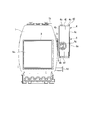
- FIG. 1 is a perspective view illustrating an overall schematic configuration of a vacuum cleaning apparatus according to a first embodiment of the present disclosure. It is a perspective view which shows the state which removed the condenser in the vacuum cleaning apparatus which concerns on 1st Embodiment of this indication. It is a front view showing a schematic structure of a vacuum cleaning device concerning a 1st embodiment of this indication. It is a perspective view showing detailed composition of a condenser concerning a 1st embodiment of this indication. It is a perspective view showing detailed composition of a cooling pipe concerning a 1st embodiment of this indication. It is a perspective view which shows the whole schematic structure of the vacuum cleaning apparatus which concerns on 2nd Embodiment of this indication.
- the vacuum cleaning apparatus includes a cleaning chamber 1, a steam generator 2, a front door 3, a drying chamber 4, a connection member 5, an opening / closing mechanism 6, a vacuum pump 7, A regeneration concentrator 8 is provided.
- the drying chamber 4 is a condenser according to the present embodiment.
- This vacuum cleaning apparatus is an apparatus for cleaning a workpiece by applying a vapor (cleaning vapor) of a cleaning agent to a workpiece (object to be cleaned) to which a dirt component is attached. That is, this vacuum cleaning apparatus supplies cleaning vapor to the cleaning chamber 1 continuously over a predetermined period (cleaning period), so that the cleaning vapor adheres and condenses on the surface of the work housed in the cleaning chamber 1. Thus, the dirt component adhering to the surface of the workpiece is washed off from the surface of the workpiece together with the condensate of the cleaning agent.
- the workpiece is a metal part in which cutting oil or the like is attached to the surface as a dirt component by processing, for example.
- Such a vacuum cleaning apparatus is installed on a predetermined pedestal so that the Z-axis is the vertical direction among the X-axis, Y-axis, and Z-axis shown as orthogonal coordinate axes in FIG.
- components that are not directly related to the features of the vacuum cleaning apparatus according to this embodiment such as various pipes and valves, are omitted for convenience.
- an actual vacuum cleaning apparatus actual machine
- a plurality of pipes and valves are mounted around each of the above-described components, and an exterior product is mounted on the outside thereof.
- the cleaning chamber 1 is formed in a hollow rectangular parallelepiped shape (substantially box shape) as a whole, and the internal space accommodates a workpiece (object to be cleaned).
- the cleaning chamber 1 is provided with an opening (work insertion port 1a) on one side surface (front surface).
- This work insertion port 1a is an opening in a vertical posture for taking in and out the work between the cleaning chamber 1 and the outside, and has a rectangular shape as shown in the figure.
- a sealing material for closely contacting the front door 3 is provided on the outer periphery of the workpiece insertion port 1a over the entire circumference.
- an exhaust port 1b is provided in the upper part of the cleaning chamber 1 and in the vicinity of the rear surface.
- the exhaust port 1b is an opening for exhausting the air in the cleaning chamber 1 to the outside, and is connected to the vacuum pump 7 by a pipe (not shown).
- a circular opening (drying chamber opening 1 c) for communicating the cleaning chamber 1 with the drying chamber 4 is formed on the side surface adjacent to the drying chamber 4 in the cleaning chamber 1. That is, the cleaning chamber 1 communicates with the drying chamber 4 via the drying chamber opening 1c.
- a drain port 1d and a steam intake port 1e are provided on the side of the cleaning chamber 1.
- the drainage port 1d is an opening for discharging the cleaning liquid generated by cleaning the workpiece and the mixed liquid of dirt components to the outside of the cleaning chamber 1, and is connected to the regeneration concentrator 8 by a pipe (not shown).
- the steam intake port 1e is an opening for taking the steam of the cleaning liquid generated in the regeneration concentrator 8 into the cleaning chamber 1, and is connected to the regeneration concentrator 8 by a pipe (not shown).
- the steam generation unit 2 is provided in the upper part of the cleaning chamber 1 and generates a cleaning agent vapor.
- the steam generating unit 2 includes, for example, a heating unit that heats the cleaning agent to generate cleaning steam and a steam tank that temporarily stores the cleaning steam, and the steam generated by the heating unit is stored in the steam tank. Once stored, cleaning steam is supplied to the cleaning chamber 1 through this steam tank. According to such a steam generation part 2, since the steam tank is provided, it is possible to stably supply cleaning steam at a predetermined flow rate to the cleaning chamber 1 over the cleaning period.
- the cleaning agent is a hydrocarbon-based cleaning agent, for example, a normal paraffin-based, isoparaffin-based, naphthene-based, or aromatic hydrocarbon-based cleaning agent. More specifically, it is a third petroleum cleaning agent such as TECLEAN (registered trademark) N20, cleaning solvent G, and Daphne solvent called cleaning solvent.
- TECLEAN registered trademark N20
- cleaning solvent G cleaning solvent G
- Daphne solvent Daphne solvent
- the front door 3 is a flat member that is provided on the front surface of the cleaning chamber 1 and closes or opens the work insertion port 1a.
- the front door 3 is, for example, a sliding door, and is disposed opposite to the vertical workpiece insertion port 1a in the same vertical posture, and moves in the left-right direction (X-axis direction) while maintaining the vertical posture, thereby moving the workpiece insertion port 1a. Close or open.
- the front door 3 seals the washing
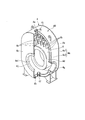
- the drying chamber 4 has a rounded box shape as shown in FIG. 1 and is a condenser that condenses (liquefies) the vapor (residual vapor) taken in from the cleaning chamber 1.
- the surface of the workpiece and the inner surface of the cleaning chamber 1 are wet with the cleaning agent.
- the drying chamber 4 takes in the vapor (residual vapor) of the cleaning agent remaining in the cleaning chamber 1 after cleaning the workpiece from the cleaning chamber 1 to condense (liquefy) it.
- the drying chamber 4 includes a first flat surface portion 4 a, a second flat surface portion 4 b, a peripheral surface portion 4 c, a hollow portion 4 d, an exhaust port 4 e, a drainage liquid.
- a port 4f, a steam intake port 4g, a refrigerant intake port 4h, a refrigerant drainage port 4i, a steam intake port 4j, a plurality of fins 4k, and a temperature holding device 4m are provided.
- a container 40 (corresponding to a container in the present disclosure) is configured by the port 4i and the steam inlet 4j.
- the first flat surface portion 4a is a plate portion provided with a plurality of fins 4k and having an oval outer periphery.
- the second plane portion 4b is a plate portion provided with a steam inlet 4j, substantially the same shape as the first plane portion 4a, and substantially parallel to the first plane portion 4a. That is, this 2nd plane part 4b is a site
- the 1st plane part 4a and the 2nd plane part 4b which are in a mutually parallel relationship are a vertical attitude
- the peripheral surface portion 4c is an endless plate portion that connects the outer periphery of the first flat surface portion 4a and the outer periphery of the second flat surface portion 4b.
- the peripheral surface portion 4 c is composed of an outer peripheral wall 4 c 1 and an inner peripheral wall 4 c 2, and has a double shell structure in which refrigerant can freely flow. That is, the peripheral surface portion 4c is a flow path (refrigerant flow path R) through which a refrigerant flows between the outer peripheral wall 4c1 and the inner peripheral wall 4c2 facing each other with a predetermined distance therebetween.
- the refrigerant flow path R communicates with the refrigerant intake port 4h and the refrigerant drainage port 4i.
- the double shell structure includes not only the peripheral surface portion 4c but also the first flat surface portion 4a.
- Such a drying chamber 4 is formed by the first flat surface portion 4a, the second flat surface portion 4b, and the peripheral surface portion 4c.
- the recess 4d is a part where a part displaced slightly from the center of the first flat part 4a is depressed over a predetermined area.
- a part of the opening / closing mechanism 6 (such as an air cylinder 6a) is attached to the bottom of the hollow part 4d (a part of the first flat surface part 4a).
- the exhaust port 4e is an opening for exhausting the air in the drying chamber 4 to the outside, and is connected to the vacuum pump 7 by a pipe (not shown).
- the drainage port 4f is an opening for draining the condensate (residual condensate) generated by condensing the residual vapor in the drying chamber 4 to the outside, and is connected to the regeneration concentrator 8 by a pipe (not shown). .
- the steam intake port 4g is an opening for taking in the steam (regenerated steam) of the cleaning liquid generated by the regeneration concentrator 8 into the drying chamber 4, and is connected to the regeneration concentrator 8 by a pipe (not shown).
- the refrigerant intake port 4h is an opening for taking in the refrigerant into the refrigerant flow path R, and is connected to the refrigerant supply unit 4m4 by a pipe (not shown).
- the refrigerant drainage port 4i is an opening for discharging the refrigerant in the refrigerant flow path R to the outside of the drying chamber 4, and is connected to the refrigerant recovery unit 4m5 by a pipe (not shown).
- the steam inlet 4j is a circular opening of a predetermined size provided in the second flat part 4b.
- the steam inlet 4j is provided at a position coinciding with the position of the recess 4d provided in the first plane portion 4a, that is, a position slightly displaced downward from the center of the oval second plane portion 4b. ing.
- the plurality of fins 4k are rectangular plate-like members provided inside the first flat surface portion 4a so as to protrude into the drying chamber 4, as shown in FIG. That is, these fins 4k are provided on the inner surface of the first flat surface portion 4a, which is the surface facing the steam inlet 4j. More specifically, these fins 4k are provided only on the upper side of the recess 4d in the first plane portion 4a, and extend in the vertical direction (Z-axis direction) and in the vertical direction and the horizontal direction. It is provided with a predetermined interval.
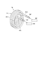
- the temperature holding device 4m is a device that holds the temperature of the drying chamber 4 (drying chamber temperature) at a predetermined temperature lower than the temperature of the cleaning chamber 1 (cleaning chamber temperature). As shown in FIG. 5, the temperature holding device 4m includes a cooling pipe 4m1, a supply side pipe end nozzle 4m2, a recovery side pipe end nozzle 4m3, a refrigerant supply unit 4m4, and a refrigerant recovery unit 4m5. .
- the cooling pipe 4m1 is a pipe through which the refrigerant flows, and has a cooling pipe center part 4m1a, a supply side cooling pipe end part 4m1b, and a recovery side cooling pipe end part 4m1c.
- the cooling pipe center part 4m1a is a main body part excluding the end part of the cooling pipe 4m1.
- the cooling pipe central part 4m1a is fixed between the recess 4d and the second flat part 4b, and is spirally wound in an oval shape having a long axis in the vertical direction. That is, the central part 4m1a of the cooling pipe is disposed in the container 40 with the central opening formed by being spirally wound facing the steam inlet 4j.
- the supply side cooling pipe end 4m1b is one end of the cooling pipe 4m1.
- the supply side cooling pipe end 4m1b passes through the bottom of the recess 4d and protrudes to the outside of the container 40, and the supply side pipe end nozzle 4m2 is mounted.
- the recovery side cooling pipe end 4m1c is the other end of the cooling pipe 4m1.
- the recovery side cooling pipe end 4m1c passes through the bottom of the recess 4d and protrudes to the outside of the container 40, and a recovery side pipe end nozzle 4m3 is mounted.
- the supply side pipe end nozzle 4m2 is connected to the refrigerant supply unit 4m4 by a pipe (not shown).
- the recovery side pipe end nozzle 4m3 is connected to the refrigerant recovery unit 4m5 by a pipe (not shown).
- the refrigerant supply unit 4m4 supplies the refrigerant to the cooling pipe 4m1.
- This refrigerant is, for example, water.
- the refrigerant recovery unit 4m5 recovers the refrigerant from the cooling pipe 4m1.
- the refrigerant recovered by the refrigerant recovery unit 4m5 is cooled again by a cooling device (not shown) and flows into the refrigerant supply unit 4m4.
- the refrigerant supply unit 4m4 also supplies the refrigerant to the refrigerant flow path R.
- the refrigerant recovery unit 4m5 also recovers the refrigerant from the refrigerant flow path R.
- the refrigerant is supplied from the refrigerant supply unit 4m4 to the cooling pipe 4m1, and the refrigerant flows through the cooling pipe central part 4m1a, whereby the inside of the drying chamber 4 is cooled, and the drying chamber temperature is maintained at a temperature lower than the cleaning chamber temperature.
- the drying chamber temperature set and held by the temperature holding device 4m is, for example, 5 to 50 ° C.
- the drying chamber temperature is set and held at a predetermined temperature by supplying a predetermined refrigerant from the refrigerant supply unit 4m4 to the refrigerant flow path R described above.
- the connecting member 5 is a cylindrical member that connects the drying chamber opening 1c of the cleaning chamber 1 and the steam inlet 4j of the drying chamber 4, and the axial direction is set in the horizontal direction (X-axis direction).
- the connecting member 5 is, for example, a cylindrical metal bellows, and is interposed between the drying chamber opening 1c and the steam inlet 4j.
- the connection member 5 is made of a metal bellows, thereby reducing the influence of thermal deformation of the cleaning chamber 1 on the drying chamber 4.
- the opening / closing mechanism 6 closes or opens the drying chamber opening 1c shown in FIG. 2, and includes an air cylinder 6a shown in FIG. 1, a valve body 6b shown in FIG.
- the air cylinder 6 a is provided in the recess 4 d so that its movable rod is in the axial direction (X-axis direction) of the connecting member 5.
- a valve body 6b is fixed to the tip of the movable rod.
- the valve body 6b is a circular member provided on the cleaning chamber 1 side of the drying chamber opening 1c, has a slightly larger shape than the drying chamber opening 1c, and is connected to the connecting member 5 side (drying chamber) of the drying chamber opening 1c. (4 side) is connected to the tip of the movable rod.
- the air cylinder 6 a operates so as to draw the movable rod, whereby the outer peripheral portion of the valve body 6 b comes into contact with the inner side surface (side surface of the cleaning chamber 1) of the drying chamber opening 1 c and is dried.
- the chamber opening 1c is closed.
- the opening / closing mechanism 6 is operated by causing the air cylinder 6a to project the movable rod, whereby the outer peripheral portion of the valve body 6b is separated from the inner side surface (side surface of the cleaning chamber 1) of the drying chamber opening 1c and dried.
- the room opening 1c is opened.
- the vacuum pump 7 is connected to the exhaust ports 1b and 4e via a pipe (not shown), and exhausts the air in the cleaning chamber 1 and the drying chamber 4 to the outside.
- the regeneration concentrator 8 is connected to the drainage ports 1d and 4f and the steam intake ports 1e and 4g via pipes (not shown), and the condensate of the cleaning agent and the dirt component collected from the cleaning chamber 1 and the drying chamber 4 is used. Among them, only the cleaning agent is re-vaporized and supplied to the cleaning chamber 1 and the drying chamber 4, and the soil components are separated and concentrated.
- the workpiece When a workpiece is cleaned with this vacuum cleaning apparatus, the workpiece is accommodated in the cleaning chamber 1 through the workpiece insertion port 1a.
- This workpiece is a product in which dirt components such as cutting oil adhere to the surface.
- the steam generating unit 2 is operated to generate cleaning steam.
- the cleaning steam has a saturated vapor pressure and a temperature near the boiling point of the cleaning liquid, for example, 80 to 140 ° C.
- the opening / closing mechanism 6 operates in parallel with the decompression process, whereby the cleaning chamber 1 and the drying chamber 4 are separated as separate rooms.
- the refrigerant supply unit 4m4 operates in the temperature holding device 4m, the refrigerant is supplied to the refrigerant flow path R and the cooling pipe 4m1, and the drying chamber temperature is lower than the cleaning chamber temperature after the completion of cleaning (for example, 5 to 5). 50 ° C.).
- the work in the cleaning chamber 1 is cleaned by sequentially supplying cleaning steam from the steam generating unit 2 to the cleaning chamber 1 over a predetermined cleaning period. That is, during the cleaning period, the adhesion and condensation of the cleaning vapor are continuously repeated on the surface of the workpiece, and the dirt component adhering to the surface of the workpiece flows down from the surface of the workpiece together with the condensate of the cleaning vapor and is removed (cleaning). Is done.
- the pressure in the cleaning chamber 1 (cleaning chamber pressure) is approximately equal to the saturated vapor pressure of the cleaning vapor, and is approximately equal to the temperature of the cleaning vapor (about 80 to 140 ° C.). Yes. That is, the cleaning chamber pressure and the cleaning chamber temperature are considerably higher than the pressure (drying chamber pressure) and temperature (drying chamber temperature) of the drying chamber 4 set and held in advance.
- the opening / closing mechanism 6 is operated to connect the cleaning chamber 1 and the drying chamber 4 in the pressure relationship and the temperature relationship. Communicate. That is, by operating the air cylinder 6a, the outer peripheral portion of the valve body 6b is suddenly displaced from a state where it is in contact with the inner side surface (side surface of the cleaning chamber 1) of the drying chamber opening 1c to a state where it is separated.
- the cleaning chamber 1 and the drying chamber 4 are connected in a short time with a relatively large area.
- the cleaning chamber pressure is rapidly reduced, and the condensate (residual liquid) of the cleaning vapor adhering to the surface of the workpiece boils (sudden boiling) instantly due to this rapid pressure reduction.
- the vapor of the residual liquid (residual vapor) generated from the surface of the workpiece is discharged from the cleaning chamber 1 (high pressure side) to the valve body 6b. And the drying chamber opening 1c, the connecting member 5 and the steam intake port 4j, and the high-speed movement to the drying chamber 4 (low pressure side).
- the residual vapor moved to the drying chamber 4 (low pressure side) condenses because the drying chamber temperature is kept lower than the cleaning chamber temperature and below the boiling point of the cleaning liquid.
- the condensation of the residual vapor in the drying chamber 4 is efficiently performed because the residual vapor is more likely to be brought into contact with the above-described member and the temperature is lowered as the surface area of the inner surface of the drying chamber 4 is increased.
- the drying chamber 4 in contrast to the condensation process of the residual steam in the drying chamber 4, the drying chamber 4 (condenser) in the present embodiment has a cooling pipe 4m1 through which the refrigerant flows inside the container 40 having the steam inlet 4j.
- the drying chamber temperature can be maintained at a temperature lower than the cleaning chamber temperature.
- the cooling pipe 4m1 in this embodiment is wound in a spiral shape. For this reason, compared with a linear cooling pipe, a surface area is large, and it is possible to reduce a drying chamber temperature efficiently. Therefore, according to this embodiment, the condensation efficiency of the drying chamber 4 can be further improved.
- the cooling pipe 4m1 in the present embodiment is arranged with the central opening formed by being spirally wound facing the steam inlet 4j. For this reason, the residual steam which flowed in vigorously from the steam inlet 4j is cooled and condensed by quickly contacting the cooling pipe 4m1. According to this embodiment, the condensation efficiency of residual steam can also be improved by this.
- the first flat surface portion 4a in the present embodiment has a double shell structure in which the refrigerant flows, the inside of the first flat surface portion 4a can be efficiently cooled. Therefore, according to the present embodiment, the condensation efficiency of the residual steam can be improved also by this. Moreover, since the surrounding surface part 4c is also provided with the double shell structure, the residual vapor
- the cooling pipe 4m1 in this embodiment is spirally wound in an elliptical shape having a long axis in the vertical direction, the condensate of the residual vapor adhering to the surface of the cooling pipe 4m1 is effectively applied to the drain port 4f.
- the condensate in the drying chamber 4 can be effectively drained to the regeneration concentrator 8.
- the drying chamber 4 (condenser) in the present embodiment is provided with a plurality of fins 4k on the inner surface of the first flat surface portion 4a that is the opposite surface of the steam inlet 4j into which residual steam flows,
- the residual steam that has flowed into the drying chamber 4 vigorously from the steam inlet 4j quickly contacts the fins 4k located at the front and condenses. Therefore, it is possible to further improve the condensation performance and the condensation efficiency.
- the cooling pipe 4m1 is spirally wound, but the present disclosure is not limited to this.
- the pipe shape of the cooling pipe may be a straight pipe. When the shape of the cooling pipe is a straight pipe, the manufacturing of the cooling pipe is facilitated.
- the cooling pipe 4m1 is spirally wound.
- the cooling pipe may have a corrugated shape.
- the cooling pipe can be installed even when the depth of the drying chamber is short, that is, even when the distance between the first plane portion and the second plane portion is narrow. For this reason, installation of a cooling pipe becomes easy.
- the plurality of fins 4k are arranged on the first plane portion.
- the plurality of fins 4k may not be installed. If it is set as the structure which does not install the several fin 4k, the manufacturing process of a drying chamber will become easy.
- the vacuum cleaning apparatus includes a cleaning chamber 11, a steam generator 12, a front door 13, a drying chamber 14, a connection member 15, an opening / closing mechanism 16, a vacuum pump 17, A refrigerant supply source 18 and a regeneration concentrator 19 are provided.
- the drying chamber 14 is a condenser according to the present embodiment.
- This vacuum cleaning apparatus cleans a workpiece by causing a vapor (cleaning vapor) of a cleaning agent to act on the workpiece (object to be cleaned) on which a dirt component adheres. It is a device to do. That is, this vacuum cleaning apparatus supplies cleaning vapor to the cleaning chamber 11 continuously over a predetermined period (cleaning period), so that the cleaning vapor adheres and condenses on the surface of the work housed in the cleaning chamber 11. Thus, the dirt component adhering to the surface of the workpiece is washed off from the surface of the workpiece together with the condensate of the cleaning agent.
- the workpiece is a metal part in which cutting oil or the like is attached to the surface as a dirt component by processing, for example.
- Such a vacuum cleaning apparatus is installed on a predetermined pedestal so that the Z-axis is the vertical direction among the X-axis, Y-axis, and Z-axis shown as orthogonal coordinate axes in FIG.
- components that are not directly related to the characteristic points of the vacuum cleaning apparatus according to the present embodiment such as various pipes and valves, are omitted for convenience.
- an actual vacuum cleaning apparatus actual machine
- a plurality of pipes and valves are mounted around each of the above-described components, and an exterior product is mounted on the outside thereof.
- the cleaning chamber 11 is formed in a hollow rectangular parallelepiped shape (substantially box shape) as a whole, and the internal space accommodates a workpiece (object to be cleaned).
- the cleaning chamber 11 is provided with an opening (work insertion port 11a) on one side surface (front surface).
- This work insertion port 11a is an opening in a vertical posture for taking in and out the work between the cleaning chamber 11 and the outside, and has a rectangular shape as shown in the figure.
- a sealing material for contacting the front door 13 is provided on the outer periphery of the workpiece insertion port 11a over the entire circumference.
- an exhaust port 11b is provided in the upper part of the cleaning chamber 11 and in the vicinity of the rear surface.
- the exhaust port 11b is an opening for exhausting the air in the cleaning chamber 11 to the outside, and is connected to the vacuum pump 17 by a pipe (not shown).
- a circular opening (drying chamber opening 1 c) for communicating the cleaning chamber 11 with the drying chamber 14 is formed on the side surface adjacent to the drying chamber 14 in the cleaning chamber 11. That is, the cleaning chamber 11 communicates with the drying chamber 14 via the drying chamber opening 11c.
- a drain port 11d and a steam intake port 11e are provided on the side of the cleaning chamber 11.
- the drainage port 11d is an opening for discharging the cleaning liquid generated by cleaning the workpiece and the mixed liquid of dirt components to the outside of the cleaning chamber 11, and is connected to the regeneration concentrator 19 by a pipe (not shown).
- the steam intake port 11e is an opening for taking the steam of the cleaning liquid generated in the regeneration concentrator 19 into the cleaning chamber 11, and is connected to the regeneration concentrator 19 by a pipe (not shown).
- the vapor generation unit 12 is provided in the upper part of the cleaning chamber 11 and generates a vapor of the cleaning agent.
- the steam generation unit 12 includes, for example, a heating unit that heats the cleaning agent to generate cleaning steam, and a steam tank that temporarily stores the cleaning steam, and the steam generated by the heating unit is stored in the steam tank. Once stored, cleaning steam is supplied to the cleaning chamber 11 through this steam tank. According to such a steam generator 12, since the steam tank is provided, it is possible to stably supply cleaning steam at a predetermined flow rate to the cleaning chamber 11 over the cleaning period.
- the cleaning agent is a hydrocarbon-based cleaning agent, for example, a normal paraffin-based, isoparaffin-based, naphthene-based, or aromatic hydrocarbon-based cleaning agent. More specifically, it is a third petroleum cleaning agent such as TECLEAN (registered trademark) N20, cleaning solvent G, and Daphne solvent called cleaning solvent.
- TECLEAN registered trademark N20
- cleaning solvent G cleaning solvent G
- Daphne solvent Daphne solvent
- the front door 13 is a flat member that is provided on the front surface of the cleaning chamber 11 and closes or opens the workpiece insertion port 11a.
- the front door 13 is, for example, a slide door, and is opposed to the vertical workpiece insertion port 11a in the same vertical posture, and moves in the left-right direction (X-axis direction) while maintaining the vertical posture, thereby moving the workpiece insertion port 11a. Close or open.
- the front door 13 seals the washing
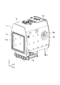
- the drying chamber 4 has a rounded box shape as shown in FIG. 6 and is a condenser that condenses (liquefies) the vapor (residual vapor) taken in from the cleaning chamber 11.
- the surface of the workpiece and the inner surface of the cleaning chamber 11 are wet with the cleaning agent.
- the drying chamber 14 takes in the vapor (residual vapor) of the cleaning agent remaining in the cleaning chamber 11 after cleaning the workpiece from the cleaning chamber 11 to condense (liquefy) it.
- the drying chamber 4 has a first flat surface portion 14 a, a second flat surface portion 14 b, a peripheral surface portion 14 c, a hollow portion 14 d, an exhaust port 14 e, a drainage liquid.
- a port 14f, a steam inlet port 14g, a refrigerant inlet port 14h, a refrigerant drainage port 14i, a steam inlet 14j, a plurality of fins 14k, and a temperature holding device 14m are provided.
- the first flat surface portion 14a is a plate portion provided with a plurality of fins 14k and having an oval outer periphery.
- the second plane portion 14b is a plate portion provided with a steam inlet 14j, substantially the same shape as the first plane portion 14a, and substantially parallel to the first plane portion 14a. That is, this 2nd plane part 14b is a site
- the 1st plane part 14a and the 2nd plane part 14b which are in a mutually parallel relationship are vertical attitude
- the peripheral surface portion 14c is an endless plate portion that connects the outer periphery of the first flat surface portion 14a and the outer periphery of the second flat surface portion 14b.
- the peripheral surface portion 14 c includes an outer peripheral wall 14 c 1 and an inner peripheral wall 14 c 2, and has a double shell structure in which refrigerant can freely flow. That is, the peripheral surface portion 14c is a flow path (refrigerant flow path R) through which a refrigerant flows between the outer peripheral wall 14c1 and the inner peripheral wall 14c2 that face each other with a predetermined distance therebetween.
- the refrigerant flow path R communicates with the refrigerant intake port 14h and the refrigerant drainage port 14i.
- the double shell structure includes not only the peripheral surface portion 14c but also the first flat surface portion 14a.
- Such a drying chamber 14 is formed by the first flat surface portion 14a, the second flat surface portion 14b, and the peripheral surface portion 14c.
- the recessed portion 14 d is a portion where a portion displaced slightly downward from the center of the first flat portion 14 a is depressed over a predetermined area.
- a part of the opening / closing mechanism 16 (such as an air cylinder 16a) is attached to the bottom of the hollow part 14d (a part of the first flat part 14a).
- the exhaust port 14e is an opening for exhausting the air in the drying chamber 14 to the outside, and is connected to the vacuum pump 17 by a pipe (not shown).
- the drainage port 14f is an opening for draining condensate (residual condensate) generated by condensation of residual vapor in the drying chamber 14, and is connected to the regeneration concentrator 19 by a pipe (not shown). .
- the steam intake port 14g is an opening for taking the cleaning solution steam (regenerated steam) generated in the regeneration concentrator 19 into the drying chamber 4, and is connected to the regeneration concentrator 19 by a pipe (not shown).
- the refrigerant intake port 14h is an opening for taking in the refrigerant into the refrigerant flow path R, and is connected to the refrigerant supply source 18 by a pipe (not shown).
- the refrigerant drain port 14i is an opening for discharging the refrigerant in the refrigerant flow path R to the outside of the drying chamber 14, and is connected to a drain tank (not shown) by a pipe (not shown).
- the steam inlet 14j is a circular opening of a predetermined size provided in the second flat part 14b.
- the steam inlet 14j is provided at a position coinciding with the position of the recess 14d provided in the first plane portion 14a, that is, a position slightly displaced downward from the center of the oval second plane portion 14b. ing.
- the plurality of fins 14 k are rectangular plate-like members provided inside the first flat surface portion 14 a so as to protrude into the drying chamber 14. That is, these fins 14k are provided on the inner side surface of the first flat surface portion 14a, which is the surface facing the steam inlet 14j. More specifically, these fins 14k are provided only on the upper side of the recess 14d in the first flat surface portion 14a, and extend in the vertical direction (Z-axis direction) and in the vertical direction and the horizontal direction. It is provided with a predetermined interval.
- the temperature holding device 14m is a device that holds the temperature of the drying chamber 14 (drying chamber temperature) at a predetermined temperature lower than the temperature of the cleaning chamber 11 (cleaning chamber temperature). As shown in FIG. 1 plane portion 14a). More specifically, the temperature holding device 14m holds the drying chamber temperature at a temperature lower than the cleaning chamber temperature by a cooling pipe (not shown) extending into the drying chamber 14.
- the drying chamber temperature set and held by the temperature holding device 14m is, for example, 5 to 50 ° C.
- the drying chamber temperature is set and maintained at a predetermined temperature by supplying a predetermined refrigerant from the refrigerant supply source 18 to the refrigerant flow path R described above.
- the connecting member 15 is a cylindrical member that connects the drying chamber opening 11c of the cleaning chamber 11 and the steam intake port 14j of the drying chamber 14, and the axial direction is set in the horizontal direction (X-axis direction).
- the connecting member 15 is, for example, a cylindrical metal bellows, and is interposed between the drying chamber opening 11c and the steam intake port 14j.
- the connection member 15 is made of a metal bellows, thereby reducing the thermal deformation of the cleaning chamber 11 from affecting the drying chamber 14.
- the opening / closing mechanism 16 closes or opens the drying chamber opening 11c shown in FIG. 7, and includes an air cylinder 16a shown in FIG. 6, a valve body 16b shown in FIG.
- the air cylinder 16 a is provided in the recess 14 d so that its movable rod is in the axial direction (X-axis direction) of the connecting member 5.
- a valve body 16b is fixed to the tip of the movable rod.
- the valve body 6b is a circular member provided on the cleaning chamber 11 side of the drying chamber opening 11c, has a slightly larger shape than the drying chamber opening 11c, and is connected to the connection member 15 side (drying chamber) of the drying chamber opening 11c. 14 side) is connected to the tip of the movable rod.
- the air cylinder 16 a operates so as to draw the movable rod, whereby the outer peripheral portion of the valve body 16 b comes into contact with the inner side surface (side surface of the cleaning chamber 11) of the drying chamber opening 11 c and is dried.
- the chamber opening 11c is closed.
- the opening / closing mechanism 16 is operated by causing the air cylinder 16a to project the movable rod, whereby the outer peripheral portion of the valve body 16b is separated from the inner side surface (side surface of the cleaning chamber 11) of the drying chamber opening 11c and dried.
- the room opening 11c is opened.
- the vacuum pump 17 is connected to the exhaust ports 11b and 14e via a pipe (not shown), and exhausts the air in the cleaning chamber 11 and the drying chamber 14 to the outside.
- the refrigerant supply source 18 is connected to the refrigerant intake port 14 h via a pipe (not shown), and supplies the refrigerant to the drying chamber 14.
- This refrigerant is, for example, water.
- the regeneration concentrator 19 is connected to the drainage ports 11d and 14f and the steam intake ports 11e and 14g via pipes (not shown), and the condensate of the cleaning agent and the dirt component collected from the cleaning chamber 11 and the drying chamber 14 is used. Among them, only the cleaning agent is re-vaporized and supplied to the cleaning chamber 11 and the drying chamber 14, and the soil components are separated and concentrated.
- the workpiece When cleaning a workpiece with this vacuum cleaning apparatus, the workpiece is accommodated in the cleaning chamber 11 through the workpiece insertion port 11a.
- This workpiece is a product in which dirt components such as cutting oil adhere to the surface.
- the steam generating unit 12 is operated to generate cleaning steam.
- the cleaning steam has a saturated vapor pressure and a temperature near the boiling point of the cleaning liquid, for example, 80 to 140 ° C.
- the cleaning chamber 11 and the drying chamber 14 are separated as separate chambers by operating the opening / closing mechanism 16 in parallel with the decompression process, and further the drying is performed by operating the temperature holding device 14m and the refrigerant supply source 18.
- the temperature of the chamber is set to a state (for example, 5 to 50 ° C.) lower than the temperature of the cleaning chamber after the cleaning is completed.
- the work in the cleaning chamber 11 is cleaned by sequentially supplying cleaning steam from the steam generating unit 12 to the cleaning chamber 11 over a predetermined cleaning period. That is, during the cleaning period, the adhesion and condensation of the cleaning vapor are continuously repeated on the surface of the workpiece, and the dirt component adhering to the surface of the workpiece flows down from the surface of the workpiece together with the condensate of the cleaning vapor and is removed (cleaning). Is done.
- the pressure in the cleaning chamber 11 is approximately equal to the saturated vapor pressure of the cleaning vapor, and is approximately equal to the temperature of the cleaning vapor (about 80 to 140 ° C.). Yes. That is, the cleaning chamber pressure and the cleaning chamber temperature are considerably higher than the pressure (drying chamber pressure) and temperature (drying chamber temperature) of the drying chamber 14 set and maintained in advance.
- a drying process of the workpiece in the cleaning chamber 11 is performed.
- the opening / closing mechanism 16 is operated to connect the cleaning chamber 11 and the drying chamber 14 having the pressure relationship and the temperature relationship. Communicate. That is, by operating the air cylinder 16a, the outer peripheral portion of the valve body 16b is suddenly displaced from a state where it is in contact with the inner side surface of the drying chamber opening 11c (side surface of the cleaning chamber 11) to a state where it is separated.
- the cleaning chamber 11 and the drying chamber 14 are connected in a short time with a relatively large area.
- the cleaning chamber pressure is rapidly reduced, and the condensate (residual liquid) of the cleaning vapor adhering to the surface of the workpiece boils (sudden boiling) instantly due to this rapid pressure reduction.
- the vapor of the residual liquid (residual vapor) generated from the surface of the workpiece is discharged from the cleaning chamber 11 (high pressure side) to the valve body 16b. And the drying chamber opening 11c, the connecting member 15 and the steam intake port 14j, and moves to the drying chamber 14 (low pressure side) at high speed.
- the residual vapor moved to the drying chamber 14 (low pressure side) condenses because the drying chamber temperature is kept lower than the cleaning chamber temperature and below the boiling point of the cleaning liquid.
- the condensation of the residual vapor in the drying chamber 14 is efficiently performed because the residual vapor is more likely to come into contact with the above-mentioned member and the temperature is lowered as the surface area of the inner surface of the drying chamber 14 increases.
- the drying chamber 14 in contrast to the condensing process of the residual steam in the drying chamber 14, the drying chamber 14 (condenser) in the present embodiment has an inner surface of the first flat surface portion 14 a that is the facing surface of the steam inlet 14 j into which the residual steam flows. Since the plurality of fins 14k are provided on the side surface, the residual steam that has flowed into the drying chamber 14 from the steam intake port 14j quickly contacts the fins 14k located on the front side and condenses. If the plurality of fins 14k are provided on the same side as the steam intake port 14j, that is, the inner surface of the second flat surface portion 14b, the plurality of fins 14k are located on the rear side with respect to the inflow direction of the residual steam. As a result, the condensation efficiency decreases.
- the plurality of fins 14k in the present embodiment are provided at predetermined intervals in the vertical direction (Z-axis direction) and the horizontal direction (Y-axis direction), that is, distributed on the opposing surface of the steam inlet 14j. Therefore, contact efficiency with residual steam is good. Therefore, according to this embodiment, the condensation efficiency of the residual steam in the drying chamber 14 can also be improved by this. Therefore, according to the present embodiment, it is possible to efficiently condense the residual steam flowing into the drying chamber 14 from the cleaning chamber 11, and thus the condensation performance can be improved as compared with the conventional case.
- the condensate of the residual vapor condensed on the surface is dropped relatively quickly and removed from the surface.
- the condensate of the residual vapor is dropped relatively quickly and removed from the surface.
- the 1st plane part 14a in this embodiment is equipped with the double shell structure through which a refrigerant
- peripheral surface portion 14c in the present embodiment is formed in an oval shape corresponding to the outer peripheral shapes of the first flat surface portion 14a and the second flat surface portion 14b, the condensate of residual steam is discharged from the drain port 14f.
- the condensate in the drying chamber 14 can be effectively drained to the regeneration concentrator 19.
- the plurality of fins 14k extend in the vertical direction (Z-axis direction) and are discretely arranged at predetermined intervals in the vertical direction (Z-axis direction) and in the horizontal direction (Y-axis direction).
- the present disclosure is not limited to this. As long as the plurality of fins 14k are provided on the opposing surface of the steam intake port 14j, other installation modes may be used.
- the outer peripheral shape of the first flat surface portion 14a and the second flat surface portion 14b and the outer shape of the peripheral surface portion 14c are oval, but instead of an oval, a circle (perfect circle shape) or an ellipse is used. You may make it a shape.
- first flat surface portion 14a and the second flat surface portion 14b are in the vertical posture, but the present disclosure is not limited to this.
- first plane portion 14a and / or the second plane portion 14b may be slightly inclined from the vertical posture.
- the condensation efficiency can be further improved by shortening the condensation period.
Abstract
本開示は、蒸気取入口(4j)を有する容器(40)を備え、蒸気取入口から容器内部に取り入れた蒸気を液化させる乾燥室(凝縮器)(4)であって、容器内部に、冷媒が流通する冷却管(4m1)を備える。
Description
本開示は、凝縮器及び洗浄装置に関する。
本願は、2014年6月30日に日本に出願された特願2014-134372号、及び、2015年6月15日に日本に出願された特願2015-120475号に基づき優先権を主張し、その内容をここに援用する。
本願は、2014年6月30日に日本に出願された特願2014-134372号、及び、2015年6月15日に日本に出願された特願2015-120475号に基づき優先権を主張し、その内容をここに援用する。
特許文献1には、炭化水素系洗浄剤の蒸気を生成する蒸気室と、蒸気室から供給される炭化水素系洗浄剤の蒸気によって減圧下でワークを洗浄する洗浄室と、開閉バルブを介して洗浄室に接続されると共に減圧状態かつ低温状態に保持された乾燥室とを備え、洗浄室におけるワークの洗浄が終了すると、開閉バルブを開弁状態とすることにより洗浄室と乾燥室とを連通させることによりワークを乾燥させる真空洗浄装置が開示されている。
すなわち、この真空洗浄装置では、減圧状態に保持された乾燥室が洗浄時の蒸気供給によって乾燥室よりも高圧状態になっている洗浄室と連通することにより、ワークに付着した洗浄液が瞬間的に気化して洗浄室から乾燥室に移動して凝縮し、以ってワークの乾燥を実現する。なお、下記特許文献2にも、特許文献1と同様な乾燥室(凝縮室)を備えた真空洗浄装置が開示されている。
ところで、近年では、生産現場において、生産性の向上のため製造工程を短時間化することが求められている。このため、真空洗浄装置においてはワークの乾燥時間の短縮が必要とされている。乾燥時間の短縮のためには、乾燥室の凝縮器としての凝縮性能を、より向上させる必要がある。
本開示は、上述した事情に鑑みてなされ、凝縮器の凝縮性能を従来よりも向上させることを目的とする。
本開示の凝縮器に係る第1の態様は、蒸気取入口を有する容器を備え、上記蒸気取入口から上記容器内部に取り入れた蒸気を液化させる凝縮器であって、上記容器内部に、冷媒が流通する冷却管を備える。
本開示の凝縮器に係る第2の態様は、上記冷却管は、螺旋状に巻回されている。
本開示の凝縮器に係る第3の態様は、上記冷却管は、螺旋状に巻回されることで形成された中央開口を上記蒸気取入口に対向させて配置されている。
本開示の凝縮器に係る第4の態様は、前記容器は、冷媒の流通が自在な二重殻構造である。
本開示の凝縮器に係る第5の態様は、鉛直姿勢に設けられる蒸気取入口から取り入れた蒸気を液化させる凝縮器であって、前記蒸気取入口の対向面に複数のフィンが設けられる。
本開示の凝縮器に係る第6の態様は、前記複数のフィンが設けられ、外周が円形あるいは長円形な第1平面部と、前記蒸気取入口が設けられ、前記第1平面部と略平行な第2平面部と、前記第1平面部の外周と前記第2平面部の外周とを接続する無端状の周面部とを備える。
本開示の凝縮器に係る第7の態様は、前記複数のフィンは、鉛直方向に延在すると共に前記鉛直方向に所定間隔を空けて設けられる。
本開示の凝縮器に係る第8の態様は、鉛直姿勢に設けられる蒸気取入口から取り入れた蒸気を液化させる凝縮器であって、前記蒸気取入口の対向面に複数のフィンが設けられ、前記対向面は、冷媒の流通が自在な二重殻構造に形成されている。
本開示の凝縮器に係る第9の態様は、上記第8の態様において、前記複数のフィンが設けられ、外周が円形あるいは長円形な第1平面部と、前記蒸気取入口が設けられ、前記第1平面部と略平行な第2平面部と、前記第1平面部の外周と前記第2平面部の外周とを接続する無端状の周面部とを備える。
本開示の凝縮器に係る第10の態様は、上記第8または第9の態様において、前記複数のフィンは、鉛直方向に延在すると共に当該鉛直方向に所定間隔を空けて設けられる。
本開示の洗浄装置に係る第11の態様は、上記第1~第10のいずれかの凝縮器を備える。
本開示によれば、乾燥室において、蒸気取入口を有する容器内部に冷却管を備えるので、乾燥室温度を洗浄室温度よりも低い温度に保持することが可能となる。これにより、乾燥室(凝縮器)の凝縮期間が短縮され、よって、凝縮性能を従来よりも向上させることができる。
以下、図面を参照して、本開示の第1実施形態について説明する。
第1実施形態に係る真空洗浄装置は、図1あるいは図3に示すように、洗浄室1、蒸気発生部2、フロントドア3、乾燥室4、接続部材5、開閉機構6、真空ポンプ7及び再生濃縮器8を備えている。なお、これら構成要素のうち、乾燥室4は本実施形態に係る凝縮器である。
第1実施形態に係る真空洗浄装置は、図1あるいは図3に示すように、洗浄室1、蒸気発生部2、フロントドア3、乾燥室4、接続部材5、開閉機構6、真空ポンプ7及び再生濃縮器8を備えている。なお、これら構成要素のうち、乾燥室4は本実施形態に係る凝縮器である。
第1実施形態に係る真空洗浄装置の概要について最初に説明する。この真空洗浄装置は、汚れ成分が付着したワーク(被洗浄物)に洗浄剤の蒸気(洗浄蒸気)を作用させることによりワークを洗浄する装置である。すなわち、この真空洗浄装置は、洗浄蒸気を所定期間(洗浄期間)に亘って連続的に洗浄室1に供給することにより、洗浄室1内に収容されたワークの表面で洗浄蒸気の付着と凝縮とを繰り返し行わせ、以ってワークの表面に付着した汚れ成分を洗浄剤の凝縮液とともにワークの表面から洗い落とす。なお、ワークは、例えば加工によって表面に切削油等が汚れ成分として付着した金属部品である。
このような真空洗浄装置は、図1に直交座標軸として示すX軸、Y軸及びZ軸のうち、Z軸が鉛直方向となるように所定の台座上に設置される。なお、この図1では、本実施形態に係る真空洗浄装置の特徴点に直接関係しない構成要素、例えば各種の配管や弁については、便宜的に省略している。実際の真空洗浄装置(実機)は、上述した各構成要素の周囲に複数の配管や弁が実装され、さらにその外側に外装品が実装されている。
洗浄室1は、全体として中空の直方体形状(略箱型)に形成されており、内部空間がワーク(被洗浄物)を収容する。この洗浄室1には、一側面(フロント面)に開口(ワーク挿通口1a)が設けられている。このワーク挿通口1aは、洗浄室1と外部との間でワークを出し入れするための鉛直姿勢の開口であり、図示するように矩形形状である。なお、このようなワーク挿通口1aの周囲外側には、フロントドア3と密着するためのシール材が全周に亘って設けられている。
また、このような洗浄室1の上部かつリヤ面近傍部位には、排気ポート1bが設けられている。この排気ポート1bは、上記洗浄室1内の空気を外部に排気するための開口であり、図示しない配管によって真空ポンプ7に接続されている。また、洗浄室1において乾燥室4と隣接する側面には、図2に示すように、洗浄室1を乾燥室4と連通させるための円形開口(乾燥室用開口1c)が形成されている。すなわち、洗浄室1は、乾燥室用開口1cを介して乾燥室4と連通する。
さらに、洗浄室1の側部には、排液ポート1dと蒸気取入ポート1eとが設けられている。排液ポート1dは、ワークの洗浄によって発生した洗浄液及び汚れ成分の混合液を洗浄室1の外部に排出するための開口であり、図示しない配管によって再生濃縮器8に接続されている。蒸気取入ポート1eは、再生濃縮器8で生成された洗浄液の蒸気を洗浄室1に取り入れるための開口であり、図示しない配管によって再生濃縮器8に接続されている。
蒸気発生部2は、洗浄室1の上部に備えられており、洗浄剤の蒸気を発生させる。この蒸気発生部2は、例えば洗浄剤を加熱して洗浄蒸気を発生させる加熱部と、洗浄蒸気を一時的に貯留する蒸気タンクとを備えており、加熱部で発生させた蒸気を蒸気タンクに一旦貯留し、この蒸気タンクを介して洗浄蒸気を洗浄室1に供給する。このような蒸気発生部2によれば、蒸気タンクを備えているので、洗浄室1に対して所定流量の洗浄蒸気を洗浄期間に亘って安定的に供給することができる。
なお、上記洗浄剤は、炭化水素系の洗浄剤、例えばノルマルパラフィン系、イソパラフィン系、ナフテン系、芳香族系の炭化水素系洗浄剤である。さらに具体的には、クリーニングソルベントと呼ばれるテクリーン(登録商標)N20、クリーンソルG、ダフニーソルベント等、第3石油類の洗浄剤である。
フロントドア3は、洗浄室1のフロント面に備えられ、上記ワーク挿通口1aを閉鎖あるいは開放する平板状部材である。このフロントドア3は、例えばスライドドアであり、鉛直姿勢のワーク挿通口1aに同じく鉛直姿勢で対向配置され、この鉛直姿勢のまま左右方向(X軸方向)に移動することによってワーク挿通口1aを閉鎖あるいは開放する。なお、フロントドア3は、ワーク挿通口1aの周囲外側(フロントドア3側)に設けられたシール材と接触することにより、洗浄室1を密閉する。
乾燥室4は、図1に示すように丸みを帯びた箱型であり、上記洗浄室1から取り込んだ蒸気(残留蒸気)を凝縮(液化)させる凝縮器である。洗浄室1でのワークの洗浄が終了した状態では、ワークの表面や洗浄室1の内面は洗浄剤で濡れた状態である。詳細については後述するが、乾燥室4は、このようなワークの洗浄後において洗浄室1に残留する洗浄剤の蒸気(残留蒸気)を洗浄室1から取り込んで凝縮(液化)させる。
このような乾燥室4は、図1に加えて図3及び図4にも示すように、第1平面部4a、第2平面部4b、周面部4c、窪み部4d、排気ポート4e、排液ポート4f、蒸気取入ポート4g、冷媒取入ポート4h、冷媒排液ポート4i、蒸気取入口4j、複数のフィン4k、温度保持装置4mを備えている。本実施形態においては、第1平面部4a、第2平面部4b、周面部4c、窪み部4d、排気ポート4e、排液ポート4f、蒸気取入ポート4g、冷媒取入ポート4h、冷媒排液ポート4i及び蒸気取入口4jによって容器40(本開示における容器に相当)が構成されている。
第1平面部4aは、複数のフィン4kが設けられ、外周が長円状の板部位である。第2平面部4bは、蒸気取入口4jが設けられ、上記第1平面部4aと略同一形状で、かつ上記第1平面部4aに略平行な板部位である。すなわち、この第2平面部4bは、第1平面部4aと同様に外周が長円形な部位である。なお、互いに平行な関係にある第1平面部4a及び第2平面部4bは、鉛直姿勢である。
周面部4cは、上記第1平面部4aの外周と上記第2平面部4bの外周とを接続する無端状の板部位である。この周面部4cは、図4に示すように、外周壁4c1と内周壁4c2とからなり、冷媒の流通が自在な二重殻構造を備えている。すなわち、周面部4cは、所定距離隔てた状態で対向する外周壁4c1と内周壁4c2との間が、冷媒が流通する流路(冷媒流路R)になっている。
この冷媒流路Rは、冷媒取入ポート4h及び冷媒排液ポート4iと連通している。なお、図4には示されていないが、上記二重殻構造は周面部4cだけではなく、第1平面部4aも二重殻構造を備えている。このような乾燥室4は、第1平面部4a、第2平面部4b及び周面部4cによって形成されている。
窪み部4dは、図1に示すように、第1平面部4aの中心から若干下に変位した部位が所定面積に亘って陥没した部位である。このような窪み部4dの底部(第1平面部4aの一部)には、開閉機構6の一部(エアーシリンダー6a等)が取り付けられている。排気ポート4eは、乾燥室4の空気を外部に排気するための開口であり、図示しない配管によって真空ポンプ7に接続されている。排液ポート4fは、残留蒸気が乾燥室4で凝縮して発生する凝縮液(残留凝縮液)を外部に排液するための開口であり、図示しない配管によって再生濃縮器8に接続されている。
蒸気取入ポート4gは、再生濃縮器8で発生させた洗浄液の蒸気(再生蒸気)を乾燥室4に取り込むための開口であり、図示しない配管によって再生濃縮器8に接続されている。冷媒取入ポート4hは、冷媒を上記冷媒流路R内に取り入れるための開口であり、図示しない配管によって冷媒供給部4m4に接続されている。冷媒排液ポート4iは、上記冷媒流路R内の冷媒を乾燥室4の外部に排出するための開口であり、図示しない配管によって冷媒回収部4m5に接続されている。
蒸気取入口4jは、上記第2平面部4bに設けられた所定サイズの円形開口である。この蒸気取入口4jは、上記第1平面部4aに設けられた窪み部4dの位置に符合する位置、つまり長円形状の第2平面部4bの中心から下側に若干変位した位置に設けられている。
複数のフィン4kは、図4に示すように、乾燥室4に突出するように第1平面部4aの内側に設けられた矩形の板状部材である。すなわち、これらフィン4kは、蒸気取入口4jの対向面である第1平面部4aの内側面に設けられている。より具体的には、これらフィン4kは、第1平面部4aにおいて窪み部4dの上方側のみに設けられており、また鉛直方向(Z軸方向)に延在すると共にこの鉛直方向及び水平方向に所定間隔を空けて設けられている。
温度保持装置4mは、乾燥室4の温度(乾燥室温度)を洗浄室1の温度(洗浄室温度)よりも低い所定温度に保持する装置である。この温度保持装置4mは、図5に示すように、冷却管4m1と、供給側管端ノズル4m2と、回収側管端ノズル4m3と、冷媒供給部4m4と、冷媒回収部4m5とを備えている。
冷却管4m1は、冷媒が流通する管であり、冷却管中央部4m1aと、供給側冷却管端部4m1bと、回収側冷却管端部4m1cとを有している。冷却管中央部4m1aは、冷却管4m1の端部を除いた本体部分である。冷却管中央部4m1aは、窪み部4dと第2平面部4bとの間に固定されており、鉛直方向に長軸をとる長円状に螺旋巻きされている。つまり、冷却管中央部4m1aは、螺旋状に巻回されることで形成された中央開口を、容器40内部に蒸気取入口4jと対向させて配置されている。
供給側冷却管端部4m1bは、冷却管4m1の一方の端部である。また、供給側冷却管端部4m1bは、窪み部4dの底部を貫通して容器40外部へと突出しており、供給側管端ノズル4m2が装着されている。回収側冷却管端部4m1cは、冷却管4m1の他方の端部である。また、回収側冷却管端部4m1cは、窪み部4dの底部を貫通して容器40外部へと突出しており、回収側管端ノズル4m3が装着されている。
供給側管端ノズル4m2は、不図示の配管によって冷媒供給部4m4へと接続している。また、回収側管端ノズル4m3は、不図示の配管によって冷媒回収部4m5へと接続している。冷媒供給部4m4は、冷媒を冷却管4m1へと供給している。この冷媒は、例えば水である。冷媒回収部4m5は、冷却管4m1から冷媒を回収している。冷媒回収部4m5により回収された冷媒は、例えば、不図示の冷却装置により再度冷却されて冷媒供給部4m4へと流入する。また、冷媒供給部4m4は、冷媒流路Rにも冷媒を供給している。また、冷媒回収部4m5は、冷媒流路Rからも冷媒を回収している。
冷媒供給部4m4から冷却管4m1に冷媒が供給され、冷却管中央部4m1aに冷媒が流通することで、乾燥室4内部は冷却され、乾燥室温度は洗浄室温度よりも低い温度に保持される。この温度保持装置4mによって設定及び保持される乾燥室温度は、例えば5~50℃である。なお、乾燥室温度は、温度保持装置4mに加えて、上述した冷媒流路Rに冷媒供給部4m4から所定の冷媒が供給されることによって所定温度に設定及び保持される。
接続部材5は、洗浄室1の乾燥室用開口1cと乾燥室4の蒸気取入口4jとを接続する円筒状部材であり、軸線方向が水平方向(X軸方向)に設定されている。この接続部材5は、例えば円筒状の金属製蛇腹であり、乾燥室用開口1cと蒸気取入口4jとの間に介装される。本実施形態に係る真空洗浄装置では、接続部材5を金属製蛇腹とすることにより、洗浄室1の熱変形が乾燥室4に影響を与えることを軽減している。
開閉機構6は、図2に示す乾燥室用開口1cを閉鎖あるいは開放するものであり、図1に示すエアーシリンダー6a、図2に示す弁体6b等から構成されている。上記エアーシリンダー6aは、自らの可動ロッドが接続部材5の軸線方向(X軸方向)となるように窪み部4dに設けられている。また、上記可動ロッドの先端には弁体6bが固定されている。弁体6bは、乾燥室用開口1cの洗浄室1側に設けられる円形部材であり、乾燥室用開口1cよりも若干大きな形状を有すると共に、乾燥室用開口1cの接続部材5側(乾燥室4側)において可動ロッドの先端に接続されている。
このような開閉機構6は、エアーシリンダー6aが可動ロッドを引き込むように作動することによって、弁体6bの外周部が乾燥室用開口1cの内側面(洗浄室1の側面)に当接して乾燥室用開口1cを閉鎖する。一方、開閉機構6は、エアーシリンダー6aが可動ロッドを突出させるように作動することによって、弁体6bの外周部が乾燥室用開口1cの内側面(洗浄室1の側面)から離間して乾燥室用開口1cを開放する。
真空ポンプ7は、図示しない配管を介して排気ポート1b、4eに接続されており、洗浄室1及び乾燥室4の空気を外部に排気する。再生濃縮器8は、図示しない配管を介して排液ポート1d、4f及び蒸気取入ポート1e、4gに接続されており、洗浄室1及び乾燥室4から回収した洗浄剤及び汚れ成分の凝縮液のうち、洗浄剤のみを再蒸気化して洗浄室1及び乾燥室4に供給すると共に汚れ成分を分離・濃縮する。
次に、このように構成された本実施形態に係る真空洗浄装置の動作について説明する。
この真空洗浄装置でワークを洗浄する場合、ワークはワーク挿通口1aから洗浄室1に収容される。このワークは表面に切削油等の汚れ成分が付着した物である。そして、フロントドア3が作動して洗浄室1及び乾燥室4が密閉空間とされる。そして、真空ポンプ7が作動して洗浄室1及び乾燥室4が徐々に減圧されて、例えば10kPa以下の圧力(初期圧力)に圧力設定される。
また、このような減圧処理に平行して、蒸気発生部2が作動して洗浄蒸気が生成される。この洗浄蒸気は、圧力が飽和蒸気圧、また温度が洗浄液の沸点近傍、例えば80~140℃である。また、上記減圧処理に平行して開閉機構6が作動することにより洗浄室1と乾燥室4とが個別の部屋として分離されている。さらに温度保持装置4mにおいて冷媒供給部4m4が作動することにより、冷媒流路Rと冷却管4m1に冷媒が供給され、乾燥室温度が洗浄終了後の洗浄室温度よりも低温な状態(例えば5~50℃)に温度設定される。
そして、このような状態で蒸気発生部2から洗浄室1に洗浄蒸気が所定の洗浄期間に亘って順次供給されることによって、洗浄室1内のワークが洗浄される。すなわち、洗浄期間において、ワークの表面では洗浄蒸気の付着と凝縮とが連続的に繰り返され、ワークの表面に付着した汚れ成分が洗浄蒸気の凝縮液と共にワークの表面から流下して除去(洗浄)される。
上記洗浄処理が終了した時点において、洗浄室1の圧力(洗浄室圧力)は洗浄蒸気の飽和蒸気圧にほぼ等しい圧力、また洗浄蒸気の温度にほぼ等しい温度(80~140℃程度)になっている。すなわち、洗浄室圧力及び洗浄室温度は、予め設定・保持された乾燥室4の圧力(乾燥室圧力)及び温度(乾燥室温度)よりもかなり高い値になっている。
上記洗浄処理に引き続いて洗浄室1内のワークの乾燥処理が行われるが、この乾燥処理では、開閉機構6を作動させることにより上記圧力関係及び温度関係にある洗浄室1と乾燥室4とを連通させる。すなわち、エアーシリンダー6aが作動することによって、弁体6bの外周部が乾燥室用開口1cの内側面(洗浄室1の側面)に当接している状態から離間する状態に急峻に変位させることにより、洗浄室1と乾燥室4とを短時間かつ比較的大きな面積で接続させる。
この結果、洗浄室圧力は急速に減圧され、この急速減圧に起因してワークの表面に付着している洗浄蒸気の凝縮液(残留液)が一瞬で沸騰(突沸)する。また、洗浄室1と乾燥室4とを短時間かつ比較的大きな面積で接続することによって、ワークの表面から発生した残留液の蒸気(残留蒸気)は洗浄室1(高圧側)から弁体6bと乾燥室用開口1cとの隙間と接続部材5と蒸気取入口4jとを経由して乾燥室4(低圧側)に高速移動する。
そして、乾燥室4(低圧側)に移動した残留蒸気は、乾燥室温度が洗浄室温度よりも低温かつ洗浄液の沸点以下に保持されているので凝縮する。ここで、乾燥室4における残留蒸気の凝縮は、乾燥室4の内面の表面積が大きい程に残留蒸気が上記部材に接触して低温化され易くなるので効率的に行われる。
ここで乾燥室4における残留蒸気の凝縮処理に対して、本実施形態における乾燥室4(凝縮器)は、蒸気取入口4jを有する容器40内部に、冷媒が流通する冷却管4m1が存在するため、乾燥室温度を洗浄室温度よりも低い温度に保持することが可能となる。これにより、乾燥室4における残留蒸気の凝縮期間が短縮され、よって、凝縮性能を従来よりも向上させることができる。
また、本実施形態における冷却管4m1は、螺旋状に巻回されている。このため、直線状の冷却管と比較して表面積が広く、乾燥室温度を効率よく低下させることが可能である。したがって、本実施形態によれば、乾燥室4の凝縮効率をさらに向上させることができる。
また、本実施形態における冷却管4m1は、螺旋状に巻回されることで形成された中央開口を蒸気取入口4jに対向させて配置されている。このため、蒸気取入口4jから勢いよく流入した残留蒸気は、速やかに冷却管4m1と接触することで冷却され凝縮する。本実施形態によれば、これによっても残留蒸気の凝縮効率を向上させることができる。
また、本実施形態における第1平面部4aは、内部に冷媒が流通する二重殻構造を備えているので、第1平面部4aの内側を効率的に冷却することが可能である。したがって、本実施形態によれば、これによっても残留蒸気の凝縮効率を向上させることができる。また、周面部4cも二重殻構造を備えているので、周面部4cの内面に付着した残留蒸気を効率よく凝縮させることができる。
また、本実施形態における冷却管4m1は、鉛直方向に長軸をとる長円状に螺旋巻きされているので、冷却管4m1表面に付着した残留蒸気の凝縮液を、排液ポート4fに効果的に集液することが可能であり、よって乾燥室4内の凝縮液を再生濃縮器8に効果的に排液することができる。
さらには、本実施形態における乾燥室4(凝縮器)は、残留蒸気が流入する蒸気取入口4jの対向面である第1平面部4aの内側面に複数のフィン4kが設けられているので、蒸気取入口4jから乾燥室4に勢い良く流入した残留蒸気は、前方に位置するフィン4kに速やかに接触して凝縮する。したがって、凝縮性能をさらに凝縮効率を向上させることができる。
なお、本開示は上記実施形態に限定されるものではなく、例えば以下のような変形例が考えられる。
(1)上記実施形態では、冷却管4m1は螺旋状に巻回されているとしたが、本開示はこれに限定されない。冷却管の管形状は直管としてもよい。冷却管の管形状を直管とすると、冷却管の製造が容易となる。
(1)上記実施形態では、冷却管4m1は螺旋状に巻回されているとしたが、本開示はこれに限定されない。冷却管の管形状は直管としてもよい。冷却管の管形状を直管とすると、冷却管の製造が容易となる。
(2)また、上記実施形態では、冷却管4m1は螺旋状に巻回されているとしたが、冷却管の管形状を波形としてもよい。冷却管を波形とすると、乾燥室の奥行きが短い場合、つまり、第1平面部と第2平面部との間隔が狭い場合でも、冷却管を設置できる。このため、冷却管の設置が容易となる。
(3)上記実施形態では、第1平面部に複数のフィン4kを配置したが、複数のフィン4kを設置しない構成にしてもよい。複数のフィン4kを設置しない構成とすると、乾燥室の製造工程が容易となる。
以下、図面を参照して、開示の第2実施形態について説明する。
第2実施形態に係る真空洗浄装置は、図6あるいは図8に示すように、洗浄室11、蒸気発生部12、フロントドア13、乾燥室14、接続部材15、開閉機構16、真空ポンプ17、冷媒供給源18及び再生濃縮器19を備えている。なお、これら構成要素のうち、乾燥室14は本実施形態に係る凝縮器である。
第2実施形態に係る真空洗浄装置は、図6あるいは図8に示すように、洗浄室11、蒸気発生部12、フロントドア13、乾燥室14、接続部材15、開閉機構16、真空ポンプ17、冷媒供給源18及び再生濃縮器19を備えている。なお、これら構成要素のうち、乾燥室14は本実施形態に係る凝縮器である。
本実施形態に係る真空洗浄装置の概要について最初に説明すると、この真空洗浄装置は、汚れ成分が付着したワーク(被洗浄物)に洗浄剤の蒸気(洗浄蒸気)を作用させることによりワークを洗浄する装置である。すなわち、この真空洗浄装置は、洗浄蒸気を所定期間(洗浄期間)に亘って連続的に洗浄室11に供給することにより、洗浄室11内に収容されたワークの表面で洗浄蒸気の付着と凝縮とを連続的に行わせ、以ってワークの表面に付着した汚れ成分を洗浄剤の凝縮液とともにワークの表面から洗い落す。なお、ワークは、例えば加工によって表面に切削油等が汚れ成分として付着した金属部品である。
このような真空洗浄装置は、図6に直交座標軸として示すX軸、Y軸及びZ軸のうち、Z軸が鉛直方向となるように所定の台座上に設置される。なお、この図6では、本実施形態に係る真空洗浄装置の特徴点に直接関係しない構成要素、例えば各種の配管や弁については、便宜的に省略している。実際の真空洗浄装置(実機)は、上述した各構成要素の周囲に複数の配管や弁が実装され、さらにその外側に外装品が実装されている。
洗浄室11は、全体として中空の直方体形状(略箱型)に形成されており、内部空間がワーク(被洗浄物)を収容する。この洗浄室11には、一側面(フロント面)に開口(ワーク挿通口11a)が設けられている。このワーク挿通口11aは、洗浄室11と外部との間でワークを出し入れするための鉛直姿勢の開口であり、図示するように矩形形状である。なお、このようなワーク挿通口11aの周囲外側には、フロントドア13と密着するためのシール材が全周に亘って設けられている。
また、このような洗浄室11の上部かつリヤ面近傍部位には、排気ポート11bが設けられている。この排気ポート11bは、上記洗浄室11内の空気を外部に排気するための開口であり、図示しない配管によって真空ポンプ17に接続されている。また、洗浄室11において乾燥室14と隣接する側面には、図7に示すように、洗浄室11を乾燥室14と連通させるための円形開口(乾燥室用開口1c)が形成されている。すなわち、洗浄室11は、乾燥室用開口11cを介して乾燥室14と連通する。
さらに、洗浄室11の側部には、排液ポート11dと蒸気取入ポート11eとが設けられている。排液ポート11dは、ワークの洗浄によって発生した洗浄液及び汚れ成分の混合液を洗浄室11の外部に排出するための開口であり、図示しない配管によって再生濃縮器19に接続されている。蒸気取入ポート11eは、再生濃縮器19で生成された洗浄液の蒸気を洗浄室11に取り入れるための開口であり、図示しない配管によって再生濃縮器19に接続されている。
蒸気発生部12は、洗浄室11の上部に備えられており、洗浄剤の蒸気を発生させる。この蒸気発生部12は、例えば洗浄剤を加熱して洗浄蒸気を発生させる加熱部と、洗浄蒸気を一時的に貯留する蒸気タンクとを備えており、加熱部で発生させた蒸気を蒸気タンクに一旦貯留し、この蒸気タンクを介して洗浄蒸気を洗浄室11に供給する。このような蒸気発生部12によれば、蒸気タンクを備えているので、洗浄室11に対して所定流量の洗浄蒸気を洗浄期間に亘って安定的に供給することができる。
なお、上記洗浄剤は、炭化水素系の洗浄剤、例えばノルマルパラフィン系、イソパラフィン系、ナフテン系、芳香族系の炭化水素系洗浄剤である。さらに具体的には、クリーニングソルベントと呼ばれるテクリーン(登録商標)N20、クリーンソルG、ダフニーソルベント等、第3石油類の洗浄剤である。
フロントドア13は、洗浄室11のフロント面に備えられ、上記ワーク挿通口11aを閉鎖あるいは開放する平板状部材である。このフロントドア13は、例えばスライドドアであり、鉛直姿勢のワーク挿通口11aに同じく鉛直姿勢で対向配置され、この鉛直姿勢のまま左右方向(X軸方向)に移動することによってワーク挿通口11aを閉鎖あるいは開放する。なお、フロントドア13は、ワーク挿通口11aの周囲外側(フロントドア13側)に設けられたシール材と接触することにより、洗浄室11を密閉する。
乾燥室4は、図6に示すように丸みを帯びた箱型であり、上記洗浄室11から取り込んだ蒸気(残留蒸気)を凝縮(液化)させる凝縮器である。洗浄室11でのワークの洗浄が終了した状態では、ワークの表面や洗浄室11の内面は洗浄剤で濡れた状態である。詳細については後述するが、乾燥室14は、このようなワークの洗浄後において洗浄室11に残留する洗浄剤の蒸気(残留蒸気)を洗浄室11から取り込んで凝縮(液化)させる。
このような乾燥室4は、図6に加えて図8及び図9にも示すように、第1平面部14a、第2平面部14b、周面部14c、窪み部14d、排気ポート14e、排液ポート14f、蒸気取入ポート14g、冷媒取入ポート14h、冷媒排液ポート14i、蒸気取入口14j、複数のフィン14k及び温度保持装置14mを備えている。
第1平面部14aは、複数のフィン14kが設けられ、外周が長円状の板部位である。第2平面部14bは、蒸気取入口14jが設けられ、上記第1平面部14aと略同一形状で、かつ上記第1平面部14aに略平行な板部位である。すなわち、この第2平面部14bは、第1平面部14aと同様に外周が長円形な部位である。なお、互いに平行な関係にある第1平面部14a及び第2平面部14bは、鉛直姿勢である。
周面部14cは、上記第1平面部14aの外周と上記第2平面部14bの外周とを接続する無端状の板部位である。この周面部14cは、図9に示すように、外周壁14c1と内周壁14c2とからなり、冷媒の流通が自在な二重殻構造を備えている。すなわち、周面部14cは、所定距離隔てた状態で対向する外周壁14c1と内周壁14c2との間に冷媒が流通する流路(冷媒流路R)になっている。
この冷媒流路Rは、冷媒取入ポート14h及び冷媒排液ポート14iと連通している。なお、図9には示されていないが、上記二重殻構造は周面部14cだけではなく、第1平面部14aも二重殻構造を備えている。このような乾燥室14は、第1平面部14a、第2平面部14b及び周面部14cによって形成されている。
窪み部14dは、図6に示すように、第1平面部14aの中心から若干下に変位した部位が所定面積に亘って陥没した部位である。このような窪み部14dの底部(第1平面部14aの一部)には、開閉機構16の一部(エアーシリンダー16a等)が取り付けられている。排気ポート14eは、乾燥室14の空気を外部に排気するための開口であり、図示しない配管によって真空ポンプ17に接続されている。排液ポート14fは、残留蒸気が乾燥室14で凝縮して発生する凝縮液(残留凝縮液)を外部に排液するための開口であり、図示しない配管によって再生濃縮器19に接続されている。
蒸気取入ポート14gは、再生濃縮器19で発生させた洗浄液の蒸気(再生蒸気)を乾燥室4に取り込むための開口であり、図示しない配管によって再生濃縮器19に接続されている。冷媒取入ポート14hは、冷媒を上記冷媒流路R内に取り入れるための開口であり、図示しない配管によって冷媒供給源18に接続されている。冷媒排液ポート14iは、上記冷媒流路R内の冷媒を乾燥室14の外部に排出するための開口であり、図示しない配管によって排液タンク(図示略)に接続されている。
蒸気取入口14jは、上記第2平面部14bに設けられた所定サイズの円形開口である。この蒸気取入口14jは、上記第1平面部14aに設けられた窪み部14dの位置に符合する位置、つまり長円形状の第2平面部14bの中心から下側に若干変位した位置に設けられている。
複数のフィン14kは、図9に示すように、乾燥室14に突出するように第1平面部14aの内側に設けられた矩形の板状部材である。すなわち、これらフィン14kは、蒸気取入口14jの対向面である第1平面部14aの内側面に設けられている。より具体的には、これらフィン14kは、第1平面部14aにおいて窪み部14dの上方側のみに設けられており、また鉛直方向(Z軸方向)に延在すると共にこの鉛直方向及び水平方向に所定間隔を空けて設けられている。
温度保持装置14mは、乾燥室14の温度(乾燥室温度)を洗浄室11の温度(洗浄室温度)よりも低い所定温度に保持する装置であり、図6に示すように窪み部14d(第1平面部14a)に設けられている。この温度保持装置14mは、より具体的には乾燥室14内に延在する冷却管(図示略)によって乾燥室温度を洗浄室温度よりも低い温度に保持する。この温度保持装置14mによって設定・保持される乾燥室温度は、例えば5~50℃である。なお、乾燥室温度は、温度保持装置14mに加えて、上述した冷媒流路Rに冷媒供給源18から所定の冷媒が供給されることによって所定温度に設定・保持される。
接続部材15は、洗浄室11の乾燥室用開口11cと乾燥室14の蒸気取入口14jとを接続する円筒状部材であり、軸線方向が水平方向(X軸方向)に設定されている。この接続部材15は、例えば円筒状の金属製蛇腹であり、乾燥室用開口11cと蒸気取入口14jとの間に介装される。本実施形態に係る真空洗浄装置では、接続部材15を金属製蛇腹とすることにより、洗浄室11の熱変形が乾燥室14に影響を与えることを軽減している。
開閉機構16は、図7に示す乾燥室用開口11cを閉鎖あるいは開放するものであり、図6に示すエアーシリンダー16a、図7に示す弁体16b等から構成されている。上記エアーシリンダー16aは、自らの可動ロッドが接続部材5の軸線方向(X軸方向)となるように窪み部14dに設けられている。また、上記可動ロッドの先端には弁体16bが固定されている。
弁体6bは、乾燥室用開口11cの洗浄室11側に設けられる円形部材であり、乾燥室用開口11cよりも若干大きな形状を有すると共に、乾燥室用開口11cの接続部材15側(乾燥室14側)において可動ロッドの先端に接続されている。
弁体6bは、乾燥室用開口11cの洗浄室11側に設けられる円形部材であり、乾燥室用開口11cよりも若干大きな形状を有すると共に、乾燥室用開口11cの接続部材15側(乾燥室14側)において可動ロッドの先端に接続されている。
このような開閉機構16は、エアーシリンダー16aが可動ロッドを引き込むように作動することによって、弁体16bの外周部が乾燥室用開口11cの内側面(洗浄室11の側面)に当接して乾燥室用開口11cを閉鎖する。一方、開閉機構16は、エアーシリンダー16aが可動ロッドを突出させるように作動することによって、弁体16bの外周部が乾燥室用開口11cの内側面(洗浄室11の側面)から離間して乾燥室用開口11cを開放する。
真空ポンプ17は、図示しない配管を介して排気ポート11b、14eに接続されており、洗浄室11及び乾燥室14の空気を外部に排気する。冷媒供給源18は、図示しない配管を介して冷媒取入ポート14hに接続されており、乾燥室14に冷媒を供給する。この冷媒は、例えば水である。再生濃縮器19は、図示しない配管を介して排液ポート11d、14f及び蒸気取入ポート11e、14gに接続されており、洗浄室11及び乾燥室14から回収した洗浄剤及び汚れ成分の凝縮液のうち、洗浄剤のみを再蒸気化して洗浄室11及び乾燥室14に供給すると共に汚れ成分を分離・濃縮する。
次に、このように構成された第2実施形態に係る真空洗浄装置の動作について詳しく説明する。
この真空洗浄装置でワークを洗浄する場合、ワークはワーク挿通口11aから洗浄室11に収容される。このワークは表面に切削油等の汚れ成分が付着した物である。そして、フロントドア13が作動して洗浄室11及び乾燥室14が密閉空間とされる。そして、真空ポンプ7が作動して洗浄室11及び乾燥室14が徐々に減圧されて、例えば10kPa以下の圧力(初期圧力)に圧力設定される。
また、このような減圧処理に平行して、蒸気発生部12が作動して洗浄蒸気が生成される。この洗浄蒸気は、圧力が飽和蒸気圧、また温度が洗浄液の沸点近傍、例えば80~140℃である。また、上記減圧処理に平行して開閉機構16が作動することにより洗浄室11と乾燥室14とが個別の部屋として分離され、さらに温度保持装置14m及び冷媒供給源18が作動することにより、乾燥室温度が洗浄終了後の洗浄室温度よりも低温な状態(例えば5~50℃)に温度設定される。
そして、このような状態で蒸気発生部12から洗浄室11に洗浄蒸気が所定の洗浄期間に亘って順次供給されることによって、洗浄室11内のワークが洗浄される。すなわち、洗浄期間において、ワークの表面では洗浄蒸気の付着と凝縮とが連続的に繰り返され、ワークの表面に付着した汚れ成分が洗浄蒸気の凝縮液と共にワークの表面から流下して除去(洗浄)される。
上記洗浄処理が終了した時点において、洗浄室11の圧力(洗浄室圧力)は洗浄蒸気の飽和蒸気圧にほぼ等しい圧力、また洗浄蒸気の温度にほぼ等しい温度(80~140℃程度)になっている。すなわち、洗浄室圧力及び洗浄室温度は、予め設定・保持された乾燥室14の圧力(乾燥室圧力)及び温度(乾燥室温度)よりもかなり高い値になっている。
上記洗浄処理に引き続いて洗浄室11内のワークの乾燥処理が行われるが、この乾燥処理では、開閉機構16を作動させることにより上記圧力関係及び温度関係にある洗浄室11と乾燥室14とを連通させる。すなわち、エアーシリンダー16aが作動することによって、弁体16bの外周部が乾燥室用開口11cの内側面(洗浄室11の側面)に当接している状態から離間する状態に急峻に変位させることにより、洗浄室11と乾燥室14とを短時間かつ比較的大きな面積で接続させる。
この結果、洗浄室圧力は急速に減圧され、この急速減圧に起因してワークの表面に付着している洗浄蒸気の凝縮液(残留液)が一瞬で沸騰(突沸)する。また、洗浄室11と乾燥室14とを短時間かつ比較的大きな面積で接続することによって、ワークの表面から発生した残留液の蒸気(残留蒸気)は洗浄室11(高圧側)から弁体16bと乾燥室用開口11cとの隙間と接続部材15と蒸気取入口14jとを経由して乾燥室14(低圧側)に高速移動する。
そして、乾燥室14(低圧側)に移動した残留蒸気は、乾燥室温度が洗浄室温度よりも低温かつ洗浄液の沸点以下に保持されているので凝縮する。ここで、乾燥室14における残留蒸気の凝縮は、乾燥室14の内面の表面積が大きい程に残留蒸気が上記部材に接触して低温化され易くなるので効率的に行われる。
このような乾燥室14における残留蒸気の凝縮処理に対して、本実施形態における乾燥室14(凝縮器)は、残留蒸気が流入する蒸気取入口14jの対向面である第1平面部14aの内側面に複数のフィン14kが設けられているので、蒸気取入口14jから乾燥室14に勢い良く流入した残留蒸気は、前方に位置するフィン14kに速やかに接触して凝縮する。仮に、複数のフィン14kが蒸気取入口14jと同一側つまり第2平面部14bの内側面に設けられていた場合には、複数のフィン14kが残留蒸気の流入方向に対して後方側に位置することになるので、凝縮効率が低下する。
また、本実施形態における複数のフィン14kは、この鉛直方向(Z軸方向)かつ水平方向(Y軸方向)に所定間隔を空けて設けられる、つまり蒸気取入口14jの対向面に分散配置されているので、残留蒸気との接触効率が良い。したがって、本実施形態によれば、これによっても乾燥室14における残留蒸気の凝縮効率を向上させることができる。したがって、本実施形態によれば、洗浄室11から乾燥室14に流入した残留蒸気を効率よく凝縮させることが可能であり、よって凝縮性能を従来よりも向上させることができる。
また、本実施形態における複数のフィン14kは、鉛直方向(Z軸方向)に延在するので、その表面で凝縮した残留蒸気の凝縮液が下方に比較的速やかに滴下してこの表面から除去される。この結果、残留蒸気の凝縮液がフィン14kの表面に滞留することを抑制できるので、本実施形態によれば、これによっても残留蒸気の凝縮効率を向上させることができる。
また、本実施形態における第1平面部14aは、内部に冷媒が流通する二重殻構造を備えているので、第1平面部14aの内側面及び複数のフィン14kを効果的に冷却することが可能である。したがって、本実施形態によれば、これによっても残留蒸気の凝縮効率を向上させることができる。また、周面部14cも二重殻構造を備えているので、周面部14cの内面に付着した残留蒸気を効率よく凝縮させることができる。
さらには、本実施形態における周面部14cは、第1平面部14a及び第2平面部14bの外周形状に対応して長円形状に形成されているので、残留蒸気の凝縮液を排液ポート14fに効果的に集液することが可能であり、よって乾燥室14内の凝縮液を再生濃縮器19に効果的に排液することができる。
なお、本開示は上記実施形態に限定されるものではなく、例えば以下のような変形例が考えられる。
(1)上記実施形態では、複数のフィン14kを鉛直方向(Z軸方向)に延在すると共にこの鉛直方向(Z軸方向)かつ水平方向(Y軸方向)に所定間隔を空けて離散配置したが、本開示はこれに限定されない。複数のフィン14kは蒸気取入口14jの対向面に設けられるものであれば、他の設置態様でもよい。
(1)上記実施形態では、複数のフィン14kを鉛直方向(Z軸方向)に延在すると共にこの鉛直方向(Z軸方向)かつ水平方向(Y軸方向)に所定間隔を空けて離散配置したが、本開示はこれに限定されない。複数のフィン14kは蒸気取入口14jの対向面に設けられるものであれば、他の設置態様でもよい。
(2)上記実施形態では、第1平面部14a及び第2平面部14bの外周形状及び周面部14cの外形を長円形状としたが、長円上に代えて円形(真円形状)や楕円形状にしてもよい。
(3)上記実施形態では、第1平面部14a及び第2平面部14bを鉛直姿勢としたが、本開示はこれに限定されない。例えば、第1平面部14a及び/あるいは第2平面部14bを鉛直姿勢から若干傾斜させてもよい。
本開示によれば、凝縮器において、凝縮期間を短縮させることで凝縮効率をより向上させることができる。
1 洗浄室
1a ワーク挿通口
1b 排気ポート
1c 乾燥室用開口
1d 排液ポート
1e 蒸気取入ポート
2 蒸気発生部
3 フロントドア
4 乾燥室(凝縮器)
4a 第1平面部
4b 第2平面部
4c 周面部
4d 窪み部
4e 排気ポート4f 排液ポート
4g 蒸気取入ポート
4h 冷媒取入ポート
4i 冷媒排液ポート
4j 蒸気取入口
4k フィン
4m 温度保持装置
4m1 冷却管
4m1a 冷却管中央部
4m1b 供給側冷却管端部
4m1c 回収側冷却管端部
4m2 供給側管端ノズル
4m3 回収側管端ノズル
4m4 冷媒供給部
4m5 冷媒回収部
40 容器
5 接続部材
6 開閉機構
6a エアーシリンダー
6b 弁体
7 真空ポンプ
8 再生濃縮器
11 洗浄室
11a ワーク挿通口
11b 排気ポート
11c 乾燥室用開口
11d 排液ポート
11e 蒸気取入ポート
12 蒸気発生部
13 フロントドア
14 乾燥室(凝縮器)
14a 第1平面部
14b 第2平面部
14c 周面部
14d 窪み部、
14e 排気ポート
14f 排液ポート
14g 蒸気取入ポート
14h 冷媒取入ポート
14i 冷媒排液ポート
14j 蒸気取入口
14k フィン
14m 温度保持装置
15 接続部材
16 開閉機構
16a エアーシリンダー
16b 弁体
17 真空ポンプ
18 冷媒供給源
19 再生濃縮器
Claims (11)
- 蒸気取入口を有する容器を備え、前記蒸気取入口から前記容器内部に取り入れた蒸気を液化させる凝縮器であって、
前記容器内部に、冷媒が流通する冷却管を備える凝縮器。 - 前記冷却管は、螺旋状に巻回されている請求項1記載の凝縮器。
- 前記冷却管は、螺旋状に巻回されることで形成された中央開口を前記蒸気取入口に対向させて配置されている請求項1または2記載の凝縮器。
- 前記容器は、冷媒の流通が自在な二重殻構造である請求項1~3のいずれか一項に記載の凝縮器。
- 鉛直姿勢に設けられる蒸気取入口から取り入れた蒸気を液化させる凝縮器であって、
前記蒸気取入口の対向面に複数のフィンが設けられる凝縮器。 - 前記複数のフィンが設けられ、外周が円形あるいは長円形な第1平面部と、
前記蒸気取入口が設けられ、前記第1平面部と略平行な第2平面部と、
前記第1平面部の外周と前記第2平面部の外周とを接続する無端状の周面部と
を備える請求項5記載の凝縮器。 - 前記複数のフィンは、鉛直方向に延在すると共に当該鉛直方向に所定間隔を空けて設けられる請求項5または6記載の凝縮器。
- 鉛直姿勢に設けられる蒸気取入口から取り入れた蒸気を液化させる凝縮器であって、
前記蒸気取入口の対向面に複数のフィンが設けられ、
前記対向面は、冷媒の流通が自在な二重殻構造に形成されている凝縮器。 - 前記複数のフィンが設けられ、外周が円形あるいは長円形な第1平面部と、
前記蒸気取入口が設けられ、前記第1平面部と略平行な第2平面部と、
前記第1平面部の外周と前記第2平面部の外周とを接続する無端状の周面部と
を備える請求項8記載の凝縮器。 - 前記複数のフィンは、鉛直方向に延在すると共に前記鉛直方向に所定間隔を空けて設けられる請求項8または9記載の凝縮器。
- 請求項1~10のいずれか一項に記載の凝縮器を備える洗浄装置。
Priority Applications (3)
| Application Number | Priority Date | Filing Date | Title |
|---|---|---|---|
| CN201580032132.5A CN106461337B (zh) | 2014-06-30 | 2015-06-30 | 冷凝器以及清洗装置 |
| EP15814540.9A EP3141856B1 (en) | 2014-06-30 | 2015-06-30 | Condenser and washing device |
| US15/358,276 US10676858B2 (en) | 2014-06-30 | 2016-11-22 | Condenser and cleaning device |
Applications Claiming Priority (4)
| Application Number | Priority Date | Filing Date | Title |
|---|---|---|---|
| JP2014134372A JP5760124B1 (ja) | 2014-06-30 | 2014-06-30 | 凝縮器及び洗浄装置 |
| JP2014-134372 | 2014-06-30 | ||
| JP2015120475A JP2017000996A (ja) | 2015-06-15 | 2015-06-15 | 凝縮器及び洗浄装置 |
| JP2015-120475 | 2015-06-15 |
Related Child Applications (1)
| Application Number | Title | Priority Date | Filing Date |
|---|---|---|---|
| US15/358,276 Continuation US10676858B2 (en) | 2014-06-30 | 2016-11-22 | Condenser and cleaning device |
Publications (1)
| Publication Number | Publication Date |
|---|---|
| WO2016002811A1 true WO2016002811A1 (ja) | 2016-01-07 |
Family
ID=55019341
Family Applications (1)
| Application Number | Title | Priority Date | Filing Date |
|---|---|---|---|
| PCT/JP2015/068903 WO2016002811A1 (ja) | 2014-06-30 | 2015-06-30 | 凝縮器及び洗浄装置 |
Country Status (4)
| Country | Link |
|---|---|
| US (1) | US10676858B2 (ja) |
| EP (1) | EP3141856B1 (ja) |
| CN (1) | CN106461337B (ja) |
| WO (1) | WO2016002811A1 (ja) |
Cited By (3)
| Publication number | Priority date | Publication date | Assignee | Title |
|---|---|---|---|---|
| JP2018004221A (ja) * | 2016-07-07 | 2018-01-11 | 株式会社Ihi | 凝縮器及び洗浄装置 |
| WO2018055934A1 (ja) * | 2016-09-21 | 2018-03-29 | 株式会社Ihi | 洗浄装置 |
| US20180236739A1 (en) * | 2017-02-23 | 2018-08-23 | Himile Mechanical Science And Technology (Shandong) Co., Ltd | Method and apparatus for cleaning workpiece, and method and apparatus for cleaning (pore-free) tire segment mold |
Citations (6)
| Publication number | Priority date | Publication date | Assignee | Title |
|---|---|---|---|---|
| JPH074889A (ja) * | 1993-06-17 | 1995-01-10 | Iwai Kikai Kogyo Kk | ガスケット自動嵌着機におけるガスケット補給装置 |
| JP2000304465A (ja) * | 1999-04-15 | 2000-11-02 | Tlv Co Ltd | 熱交換器 |
| JP2004053031A (ja) * | 2002-07-16 | 2004-02-19 | Tlv Co Ltd | 熱交換器 |
| JP2008045775A (ja) * | 2006-08-11 | 2008-02-28 | Denso Corp | エジェクタ式冷凍サイクルユニット |
| WO2013183113A1 (ja) * | 2012-06-05 | 2013-12-12 | 三菱電機株式会社 | プレート式熱交換器及びそれを備えた冷凍サイクル装置 |
| JP2014073453A (ja) * | 2012-10-04 | 2014-04-24 | Ihi Corp | 真空洗浄装置 |
Family Cites Families (20)
| Publication number | Priority date | Publication date | Assignee | Title |
|---|---|---|---|---|
| US2573966A (en) * | 1947-02-19 | 1951-11-06 | Us Hoffman Machinery Corp | Method of dry cleaning |
| US2986893A (en) * | 1960-02-01 | 1961-06-06 | Devenco Inc | Vapor recovery unit |
| US3308839A (en) * | 1964-10-12 | 1967-03-14 | Donald J Barday | Method and apparatus for cleaning objects with solvent |
| US3482625A (en) * | 1968-04-03 | 1969-12-09 | William R Bray | Two phase heat exchanger |
| US3834448A (en) * | 1969-04-04 | 1974-09-10 | R Cooksley | Heat transfer method and apparatus |
| CH593470A5 (en) * | 1975-07-10 | 1977-11-30 | Schulthess Ad Maschinenfabrik | Heat exchanger, esp. for use in textile dyeing - has automatic completely independently regulated heating and cooling systems |
| DE2927193A1 (de) * | 1979-07-05 | 1981-01-15 | Koerting Hannover Ag | Vorrichtung zum erwaermen von fluessigkeiten |
| US5820641A (en) * | 1996-02-09 | 1998-10-13 | Mks Instruments, Inc. | Fluid cooled trap |
| JP2838688B2 (ja) | 1996-08-22 | 1998-12-16 | アクア化学株式会社 | 真空洗浄装置 |
| JPH11159977A (ja) * | 1997-11-27 | 1999-06-15 | Nippon Sanso Kk | ガス冷却装置 |
| KR20020096794A (ko) * | 2001-06-20 | 2002-12-31 | 장병만 | 이화학용 수냉식 이중냉각기 |
| FR2835046B1 (fr) * | 2002-01-21 | 2004-05-28 | Rhodia Polyamide Intermediates | Serpentin de circulation d'un fluide caloporteur, procede de fabrication d'un tel serpentin et reacteur comprenant un tel serpentin |
| FR2875894B1 (fr) * | 2004-09-24 | 2006-12-15 | Valeo Climatisation Sa | Dispositif combine d'echangeur de chaleur interne et d'accumulateur pour un circuit de climatisation |
| JP2006226660A (ja) | 2005-02-21 | 2006-08-31 | Ebara Shinwa Ltd | 片吸込み型の直交流式の小型冷却塔 |
| CN2879085Y (zh) * | 2006-04-03 | 2007-03-14 | 天津三延精密机械有限公司 | 真空提取浓缩包装机的冷凝装置 |
| CN201488605U (zh) * | 2009-06-11 | 2010-05-26 | 中钢集团吉林机电设备有限公司 | 空冷式旋风冷却器 |
| CN201488607U (zh) * | 2009-08-07 | 2010-05-26 | 新疆农垦科学院农业新技术推广服务中心 | 一种用于以氨为原料生产铵盐的冷却结晶装置 |
| CN103619430B (zh) * | 2011-06-20 | 2016-02-10 | 普莱克斯技术有限公司 | 用于低温冷凝的系统和方法 |
| JP2013029228A (ja) | 2011-07-27 | 2013-02-07 | Toshiba Corp | 直接接触式復水器 |
| CN202823972U (zh) * | 2011-11-25 | 2013-03-27 | 株式会社Ihi | 真空清洗装置 |
-
2015
- 2015-06-30 CN CN201580032132.5A patent/CN106461337B/zh active Active
- 2015-06-30 WO PCT/JP2015/068903 patent/WO2016002811A1/ja active Application Filing
- 2015-06-30 EP EP15814540.9A patent/EP3141856B1/en active Active
-
2016
- 2016-11-22 US US15/358,276 patent/US10676858B2/en active Active
Patent Citations (6)
| Publication number | Priority date | Publication date | Assignee | Title |
|---|---|---|---|---|
| JPH074889A (ja) * | 1993-06-17 | 1995-01-10 | Iwai Kikai Kogyo Kk | ガスケット自動嵌着機におけるガスケット補給装置 |
| JP2000304465A (ja) * | 1999-04-15 | 2000-11-02 | Tlv Co Ltd | 熱交換器 |
| JP2004053031A (ja) * | 2002-07-16 | 2004-02-19 | Tlv Co Ltd | 熱交換器 |
| JP2008045775A (ja) * | 2006-08-11 | 2008-02-28 | Denso Corp | エジェクタ式冷凍サイクルユニット |
| WO2013183113A1 (ja) * | 2012-06-05 | 2013-12-12 | 三菱電機株式会社 | プレート式熱交換器及びそれを備えた冷凍サイクル装置 |
| JP2014073453A (ja) * | 2012-10-04 | 2014-04-24 | Ihi Corp | 真空洗浄装置 |
Non-Patent Citations (1)
| Title |
|---|
| See also references of EP3141856A4 * |
Cited By (4)
| Publication number | Priority date | Publication date | Assignee | Title |
|---|---|---|---|---|
| JP2018004221A (ja) * | 2016-07-07 | 2018-01-11 | 株式会社Ihi | 凝縮器及び洗浄装置 |
| WO2018055934A1 (ja) * | 2016-09-21 | 2018-03-29 | 株式会社Ihi | 洗浄装置 |
| US20180236739A1 (en) * | 2017-02-23 | 2018-08-23 | Himile Mechanical Science And Technology (Shandong) Co., Ltd | Method and apparatus for cleaning workpiece, and method and apparatus for cleaning (pore-free) tire segment mold |
| US10981345B2 (en) * | 2017-02-23 | 2021-04-20 | Himile Mechanical Science And Technology (Shandong) Co., Ltd | Method and apparatus for cleaning workpiece, and method and apparatus for cleaning (pore-free) tire segment mold |
Also Published As
| Publication number | Publication date |
|---|---|
| US20170073879A1 (en) | 2017-03-16 |
| CN106461337A (zh) | 2017-02-22 |
| CN106461337B (zh) | 2019-01-29 |
| EP3141856A4 (en) | 2018-01-17 |
| US10676858B2 (en) | 2020-06-09 |
| EP3141856A1 (en) | 2017-03-15 |
| EP3141856B1 (en) | 2019-07-24 |
Similar Documents
| Publication | Publication Date | Title |
|---|---|---|
| WO2016002811A1 (ja) | 凝縮器及び洗浄装置 | |
| JP7223075B2 (ja) | 熱質量が小さい加圧チャンバ | |
| JP6403703B2 (ja) | 圧縮空気の冷却乾燥方法およびその冷却乾燥装置 | |
| JP6014630B2 (ja) | 洗浄装置 | |
| JP5760124B1 (ja) | 凝縮器及び洗浄装置 | |
| JP2013055292A (ja) | 洗浄乾燥装置 | |
| JP6007275B2 (ja) | 凝縮器及び洗浄装置 | |
| JP2005085803A (ja) | サセプタ | |
| JP2017000996A (ja) | 凝縮器及び洗浄装置 | |
| JP2020081948A (ja) | 洗浄機、及び、対象物の洗浄および乾燥方法 | |
| JP6043644B2 (ja) | 真空冷却装置 | |
| KR101110049B1 (ko) | 방해판을 공유하는 냉각식 제습장치의 열교환기의 구조 | |
| KR101966648B1 (ko) | 기판세정장치 | |
| US20190193123A1 (en) | Cleaning device | |
| CN103256829A (zh) | 一种工业水冷却装置 | |
| KR102038553B1 (ko) | 볼텍스 튜브를 이용한 직접 접촉식 절삭유 냉각시스템 | |
| JP3173270U (ja) | ヒートパイプ | |
| CN205570029U (zh) | 一种三氧化硫去除装置 | |
| CN107388640A (zh) | 一种紧凑型自清洁式蒸发器 | |
| CN208825132U (zh) | 洗瓶机蒸汽冷凝装置 | |
| JP2015020108A (ja) | 真空洗浄装置 | |
| JP2020121291A (ja) | 圧縮空気の冷却乾燥方法およびその冷却乾燥装置 | |
| KR200432789Y1 (ko) | 열교환기용 소음저감장치 | |
| CN208520255U (zh) | 一种汽车冷凝器清洗装置 | |
| JP3133266U (ja) | 圧縮空気の省エネ供給装置 |
Legal Events
| Date | Code | Title | Description |
|---|---|---|---|
| 121 | Ep: the epo has been informed by wipo that ep was designated in this application |
Ref document number: 15814540 Country of ref document: EP Kind code of ref document: A1 |
|
| REEP | Request for entry into the european phase |
Ref document number: 2015814540 Country of ref document: EP |
|
| WWE | Wipo information: entry into national phase |
Ref document number: 2015814540 Country of ref document: EP |
|
| NENP | Non-entry into the national phase |
Ref country code: DE |