WO2015194437A1 - Dispositif de climatisation pour véhicule - Google Patents
Dispositif de climatisation pour véhicule Download PDFInfo
- Publication number
- WO2015194437A1 WO2015194437A1 PCT/JP2015/066762 JP2015066762W WO2015194437A1 WO 2015194437 A1 WO2015194437 A1 WO 2015194437A1 JP 2015066762 W JP2015066762 W JP 2015066762W WO 2015194437 A1 WO2015194437 A1 WO 2015194437A1
- Authority
- WO
- WIPO (PCT)
- Prior art keywords
- air
- evaporator
- heater core
- vehicle
- passage
- Prior art date
Links
Images
Classifications
-
- B—PERFORMING OPERATIONS; TRANSPORTING
- B60—VEHICLES IN GENERAL
- B60H—ARRANGEMENTS OF HEATING, COOLING, VENTILATING OR OTHER AIR-TREATING DEVICES SPECIALLY ADAPTED FOR PASSENGER OR GOODS SPACES OF VEHICLES
- B60H1/00—Heating, cooling or ventilating [HVAC] devices
Definitions
- the present invention relates to a vehicle air conditioner that is mounted on a vehicle and blows air whose temperature has been adjusted by a heat exchanger into a vehicle compartment to adjust the temperature of the vehicle compartment.
- a vehicle air conditioner mounted on a vehicle takes in inside and outside air with an air blower into an air conditioning case having an air passage, and is a cooling means. After the air cooled by the evaporator and the air heated by the heater core which is the heating means are mixed at a desired mixing ratio in the air conditioning case by driving the air mix door, for example, provided in the air conditioning case The temperature is adjusted by blowing air into the vehicle compartment through the air ducts from the plurality of openings.
- the above-mentioned evaporator when the air passes through the heat exchange section in which the refrigerant circulates, the water contained in the air adheres as condensed water, so the above-mentioned evaporator may be attached to the heater core disposed downstream.
- a protruding plate is provided to prevent movement of the condensed water to the heater core side.
- the projecting plate is erected at a predetermined height vertically upward from the bottom wall of the air conditioning case, so that the condensed water is prevented from moving toward the heater core disposed on the downstream side of the evaporator by air flow or the like. doing.
- the projecting plate also functions as a seating portion on which an upper end portion of the air mixing door which mixes hot air and cold air is seated.
- the projecting plate of the vehicle air conditioner described above is erected so as to be substantially orthogonal to the blowing direction of the air flowing from the evaporator to the heater core, and extends to nearly half the height dimension of the evaporator. Therefore, the air flow resistance when the air flows will be increased.
- the projecting plate also serves as a seat portion on which the air mix door is seated, when the cantilevered plate-like door having the rotation shaft at one end is formed, the air mix door is miniaturized, Since it is necessary to raise the upper end of the projecting plate, which is the seating portion, by a certain amount, the air flow resistance is further increased.
- a general object of the present invention is to provide a vehicle air conditioner capable of reducing the air flow resistance and improving the heat exchange efficiency while preventing the condensed water of the evaporator from moving to the heater core side. is there.
- the present invention relates to a vehicle air conditioner having an air conditioning case having a flow path through which air flows, an evaporator provided inside the air conditioning case for cooling the air, and a heater core for heating the air,
- the lower end of the heat exchange portion of the heater core is located above the lower end of the heat exchange portion of the evaporator in the direction of gravity, and the evaporator and the heater core are arranged to be substantially parallel to each other.
- a guide surface is provided which linearly connects the lower end of the heat exchange unit in the evaporator and the lower end of the heat exchange unit in the heater core.
- the evaporator and the heater core are disposed substantially in parallel and inclined to each other in the air conditioning case of the vehicle air conditioner, and the lower end of the heat exchange portion of the heater core is above the lower end of the heat exchange portion of the evaporator in the gravity direction
- the lower end of the heat exchange portion in the evaporator and the lower end of the heat exchange portion in the heater core are linearly connected by the guide surface.
- the condensed water attached to the evaporator is reliably prevented from moving to the heater core side.
- the air having passed through the heat exchange section of the evaporator can be smoothly circulated along the guide surface to the heat exchange section of the heater core.
- the air blowing resistance can be significantly reduced, and the heat of the heater core can be reduced. Exchange efficiency can be improved.
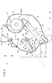
- the vehicle air conditioner 10 includes an air conditioning case 12 constituting air passages, a blower 14 disposed inside the air conditioning case 12, and an evaporator 16 for cooling the air.
- the heater core 18 heats the air, and the damper mechanism 20 switches the flow of the air flowing in the respective passages.
- the left side (arrow A direction) of the vehicle air conditioner 10 shown in FIG. 1 will be referred to as the front side of the vehicle, and the right side (arrow B direction) will be described as the rear side of the vehicle.
- the air conditioning case 12 includes, for example, substantially symmetrical first and second divided cases 22 and 24 and a lower case 26 mounted below the first and second divided cases 22 and 24.
- the first and second divided cases 22 and 24 can be divided in the width direction orthogonal to the longitudinal direction of the vehicle (directions of arrows A and B in FIG. 1), while the lower case 26 is a first divided case. 22 and the second divided case 24 are provided.
- a defroster vent 30 for blowing air in the vicinity is open.
- the vent vent 28 is formed adjacent to the vehicle rear side (arrow B direction) and the defroster vent 30 is on the vehicle front side (arrow A).
- blower 14 is accommodated in the air conditioning case 12 at a position on the upper side (arrow C1 direction) and on the rear side of the vehicle (arrow B direction).
- the blower 14 is provided at, for example, a substantially central portion in the width direction of the air conditioning case 12 so as to straddle between the first divided case 22 and the second divided case 24 and is a drive source comprising a motor etc. 32 and a fan 34 having a plurality of fins on the circumferential surface and connected to the drive shaft of the drive source 32.
- a spiral air passage 36 is formed in the air conditioning case 12 so as to surround the outer peripheral side of the air blower 14, and the air passage 36 is viewed clockwise from the lower side of the air blower 14 as viewed from the first divided case 22 side. It is formed and extends toward the vehicle front side (arrow A direction) while the passage sectional area gradually increases.
- a first passage 38 is formed in the lower case 26 below the air passage 36 (in the direction of arrow C2), and the first passage 38 is gradually inclined downward toward the vehicle front side (the direction of arrow A). And is formed upstream of the evaporator 16. Then, after the air taken in from the outside is circulated in a spiral along the air passage 36 under the driving action of the blower 14, the air is taken to the first passage 38 formed on the lower side of the air conditioning case 12 (arrow C2 direction). It flows and is supplied to the evaporator 16.
- the evaporator 16 is provided, for example, between a pair of first and second tanks 40 and 42 arranged in parallel and supplied / discharged with a refrigerant, the first tank 40 and the second tank 42, and a plurality of evaporators 16 And a first heat exchange unit (heat exchange unit) 44 including the tubes, and the first and second tanks 40 and 42 are connected to both ends of the plurality of tubes.
- the evaporator 16 is inclined at a predetermined angle so that the first tank 40 at the upper end thereof is at the vehicle rear side (arrow B direction) and the second tank 42 at the lower end is on the vehicle front side (arrow A). And the first tank 40 is disposed below the blower 14 (in the direction of the arrow C2).
- the refrigerant circulates from the first tank 40 to the second tank 42 through the plurality of tubes in the first heat exchange unit 44, and the fins provided between the tubes in the first heat exchange unit 44 By passing the air from the one passage 38, heat exchange between the air and the refrigerant is performed, and the cooled air is supplied to the downstream side (the second passage 46 side) of the evaporator 16.
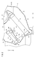
- the air conditioning case 12 is provided with a second passage 46 on the downstream side of the evaporator 16, and an air mix damper 48 that constitutes the damper mechanism 20 is provided in the second passage 46.
- a heater core 18 is provided on the downstream side of the second passage 46 at the vehicle front side (the direction of the arrow A).
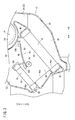
- the second passage 46 communicates with the third passage 50 extending to the vent air outlet 28 on the vehicle rear side (the direction of the arrow B), and the second passage 46 and the heater core 18 or the third passage 50 communicate with each other. Is switched by the air mix damper 48.
- the second passage 46 is formed such that a bottom surface (guide surface) 46a on the lower side (direction of arrow C2) is inclined upward from the evaporator 16 side to the heater core 18 side, and is planar Is formed. That is, the bottom surface 46 a of the second passage 46 is formed in a straight line inclined at a predetermined angle such that one end on the evaporator 16 side is downward and the other end on the heater core 18 is upward. In other words, the bottom surface 46 a of the second passage 46 extends substantially orthogonal to the height direction of the evaporator 16.
- One end of the bottom surface 46 a is formed to be substantially flush with the boundary between the second tank 42 of the evaporator 16 and the first heat exchange unit 44, that is, the lower end 44 a of the first heat exchange unit 44. .
- the third passage 50 is formed at a position on the vehicle front side (direction of arrow A) with respect to the blower 14 and moves upward (direction of arrow C1) toward the vent air outlet 28. And extend substantially in a straight line.
- the heater core 18 is provided, for example, between a pair of third and fourth tanks 54 and 56 arranged in parallel and supplied / discharged with hot water, the third tank 54 and the fourth tank 56, And a second heat exchange unit (heat exchange unit) 58 including the tubes, and both ends of the plurality of tubes are connected to the third and fourth tanks 54 and 56, respectively.
- a second heat exchange unit heat exchange unit
- the heater core 18 is inclined at a predetermined angle so that the third tank 54 at the upper end thereof is the vehicle rear side (arrow B direction) and the fourth tank 56 at the lower end is the vehicle front side (arrow A). Are disposed substantially in parallel with the evaporator 16 with the second passage 46 interposed therebetween.
- warm water is circulated from the third tank 54 to the fourth tank 56 through the plurality of tubes in the second heat exchange section 58, and air from the second passage 46 is supplied to the fins provided between the tubes.
- air from the second passage 46 is supplied to the fins provided between the tubes.
- heat exchange between the air and the hot water is performed, and the heated air is supplied to the fourth passage 52 formed on the downstream side of the heater core 18. That is, in the heater core 18, heat is exchanged by the air passing through the second heat exchange unit 58.
- the fourth tank 56 of the heater core 18 is formed so that the boundary (lower end 58a) with the second heat exchange section 58 is substantially flush with the bottom surface 46a of the second passage 46, and the other bottom surface 46a. It is arranged adjacent to the end. In other words, the lower end 58a of the second heat exchanging portion 58 of the heater core 18 and the bottom surface 46a of the second passage 46 are formed to be substantially flush with each other.
- the bottom surface 46 a of the second passage 46 is formed so as to be substantially orthogonal to the evaporator 16 and the heater core 18 which are disposed at an angle.
- the angle between the evaporator 16 and the heater core 18 and the bottom surface 46a is about 90 °.
- the inclination angle ⁇ of the evaporator 16 and the heater core 18 described above is set to be within the range of about 15 ° to 55 ° with respect to the imaginary horizontal plane S.
- the inclination angle ⁇ is, for example, the lower end of the evaporator 16 (the lower end of the first heat exchange unit 44 even when the vehicle equipped with the vehicle air conditioner 10 including the evaporator 16 and the heater core 18 inclines on a steep slope).
- the lower end of the heater core 18 (the lower end 58a of the second heat exchange section 58) does not become lower than in the direction of gravity than in 44a), and the heater core 18 is always above the evaporator 16 in the direction of gravity (arrow C1 direction) It is preset by such an angle that it becomes.
- the bottom surface 46 a of the second passage 46 is formed in a plane that linearly connects the lower end 44 a of the first heat exchange unit 44 in the evaporator 16 and the lower end 58 a of the second heat exchange unit 58 in the heater core 18.
- it may be integrally formed with the air conditioning case 12, or another member may be provided to the air conditioning case 12.
- the damper mechanism 20 includes an air mix damper 48 provided between the evaporator 16 and the heater core 18, a first switching damper 60 for switching the air blowing state of the vent air outlet 28 and the defroster air outlet 30, a third passage 50 and a fourth It has the 2nd switching damper 62 provided between the channel
- the air mix damper 48 is formed, for example, in the shape of a curved plate and is provided along the width direction of the air conditioning case 12, and guide means (not shown) provided on the inner wall surface of the air conditioning case 12 at both sides thereof. Slide along.
- a rack gear 64 is provided on the inner wall surface of the air mix damper 48 along the sliding direction of the air mix damper 48, and the pinion gear of the shaft 66 axially supported by the air conditioning case 12 is engaged.
- seal members 68 a and 68 b are provided at both end portions along the moving direction of the air mix damper 48.
- the air mix damper 48 is slid and displaced in a substantially horizontal direction along the guide means by the rotation of the shaft 66 under the action of an actuator (not shown), and the air mix damper 48 faces the heater core 18 in the second passage 46 (see FIG. 2). It is provided so as to be movable from the reference) to a position facing the third passage 50 (see FIG. 3). Then, by moving the air mix damper 48, the mixing ratio of the air (cold air) cooled by the evaporator 16 and the air (warm air) heated by the heater core 18 is adjusted and the air is blown downstream.
- the seal member 68 a provided at the end thereof is sealed by coming into contact with the bottom surface 46 a of the second passage 46.
- the seal member 68 b is sealed by coming into contact with the inner wall surface of the air conditioning case 12 when it moves to the position facing the rear surface.
- the first switching damper 60 is pivotally supported between the vent air outlet 28 and the defroster air outlet 30, and is rotated about a shaft portion by a predetermined angle under the action of an actuator (not shown), whereby the third passage 50 is formed. And the vent air outlet 28 and the defroster air outlet 30 are switched.
- the second switching damper 62 is formed in a fan shape in cross section, and the shaft portion is axially supported with respect to the first and second divided cases 22 and 24, respectively. By rotating only, the communication state between the fourth passage 52, the third passage 50, and the foot air outlet (not shown) is switched.
- the vehicle air conditioner 10 according to the embodiment of the present invention is basically configured as described above, and next, its operation and effects will be described.
- the blower 14 is driven based on a control signal from a controller (not shown) so that air is sucked into the air conditioning case 12 through the inlet (not shown) and the air swirls along the air passage 36. After flowing downward, heat is exchanged by passing through the evaporator 16 and cooled to a predetermined temperature.
- the air mix damper 48 slides toward the rear side of the vehicle (the direction of arrow B) by a predetermined distance, and the seal member 68 b contacts the inner wall surface of the air conditioning case 12. By being in contact with each other, the communication between the second passage 46 and the third passage 50 is blocked.
- the air blown from the blower 14 is cooled by passing through the first heat exchange section 44 of the evaporator 16, and then flows to the heater core 18 side through the second passage 46.
- the bottom surface 46 a of the second passage 46 is provided in a planar shape so as to connect the lower end 44 a of the first heat exchange unit 44 in the evaporator 16 and the lower end 58 a of the second heat exchange unit 58 in the heater core 18. Air can be smoothly flowed to the heater core 18 side on the downstream side in the second passage 46.
- water contained in the air may be cooled when it passes through the first heat exchange unit 44 and may be attached as condensed water, and the condensed water may be attached to the first heat exchange under the action of gravity. After moving to the second tank 42 side along the portion 44, the air falls into the air conditioning case 12. Under the present circumstances, since the heater core 18 is arrange
- the air flowing through the second passage 46 is heated to a predetermined temperature by passing through the second heat exchange portion 58 of the heater core 18 and flows upward through the fourth passage 52, and then a car from a foot air outlet etc. It is blown into the room.
- the evaporator 16 and the heater core 18 are disposed substantially in parallel and inclined to each other in the air conditioning case 12 constituting the vehicle air conditioner 10, and the second heat exchange in the heater core 18 is performed.
- a lower end 58a of the portion 58 is provided above the lower end 44a of the first heat exchanging portion 44 of the evaporator 16 in the direction of gravity (in the direction of the arrow C1).
- the bottom surface 46 a of the second passage 46 connecting the evaporator 16 and the heater core 18 is constituted by the lower end 44 a of the first heat exchanging portion 44 in the evaporator 16 and the lower end 58 a of the second heat exchanging portion 58 in the heater core 18. It is formed in a straight line to be connected.
- the condensed water attached to the evaporator 16 is moved to the heater core 18 side. Is prevented. Further, with the air mix damper 48 moved to the third passage 50 side (see FIG. 3), the air having passed through the first heat exchanging portion 44 of the evaporator 16 is made along the bottom surface 46 a of the second passage 46. It can be made to distribute
- the blowing resistance of the air can be significantly reduced, Accordingly, the heat exchange efficiency of the heater core 18 can be improved by enabling the air to pass uniformly to the second heat exchange unit 58.
- the conventional plate-like damper can be used.
- the seat portion can be used as the bottom surface 46 a of the second passage 46 by appropriately setting the moving amount of the air mix damper 48. Therefore, by raising the seat portion, the air flow resistance can be smoothly distributed without increasing the air flow resistance, as compared with the vehicle air conditioner according to the related art in which the air flow resistance is increased.
- the slide type air mix damper 48 there is no need to secure a pivoting space which is required when the plate-like damper is pivoted about the rotary shaft, so the evaporator 16 and the heater core 18 are used. It is possible to reduce the separation distance between As a result, space saving in the air conditioning case 12 can be achieved, and the vehicle air conditioner 10 can be miniaturized.
- the seal member 68 a of the air mix damper 48 is provided so as to protrude toward the bottom surface 46 a of the second passage 46.
- the seal member 68a can be reliably abutted against the bottom surface 46a, and the seal member 68a abuts. Since it is not necessary to make the second passage 46 side protrude, it is preferable without increasing the air flow resistance of the air flowing through the second passage 46.
- the vehicle air conditioner 10 including the evaporator 16 and the heater core 18 Even when the mounted vehicle is inclined on a steep slope or the like, the evaporator 16 and the heater core 18 do not become substantially parallel, and the heater core 18 is always above the evaporator 16 in the gravity direction (arrow C1 direction) Will be placed. Therefore, even when the vehicle is inclined on a slope or the like, the condensed water adhering to the evaporator 16 is prevented from moving to the heater core 18 side.
- the vehicle air conditioner according to the present invention is, of course, not limited to the above embodiment, and various configurations can be adopted without departing from the scope of the present invention.
Landscapes
- Physics & Mathematics (AREA)
- Thermal Sciences (AREA)
- Engineering & Computer Science (AREA)
- Mechanical Engineering (AREA)
- Air-Conditioning For Vehicles (AREA)
Abstract
Un dispositif de climatisation (10) pour un véhicule est configuré de telle manière que : un évaporateur (16) et un radiateur de chauffage (18) sont disposés à l'intérieur d'un caisson de climatisation (12) de manière à être inclinés et sensiblement parallèles l'un par rapport à l'autre ; et le radiateur de chauffage (18) est mis en œuvre au-dessus de l'évaporateur (16) dans la direction gravitationnelle. Un deuxième passage (46) situé entre l'évaporateur (16) et le radiateur de chauffage (18) est formé de telle sorte que la surface inférieure (46a) du deuxième passage (46) relie l'extrémité inférieure (44a) d'un premier échangeur de chaleur (44) pour l'évaporateur (16) et l'extrémité inférieure (58a) d'un deuxième échangeur de chaleur (58) pour le radiateur de chauffage (18). Par conséquent, l'air qui s'écoule au travers du deuxième passage (46) est mené en douceur jusqu'au côté radiateur de chauffage (18) le long de la surface inférieure (46a).
Priority Applications (1)
| Application Number | Priority Date | Filing Date | Title |
|---|---|---|---|
| CN201580032182.3A CN106457966B (zh) | 2014-06-19 | 2015-06-10 | 车辆用空调装置 |
Applications Claiming Priority (2)
| Application Number | Priority Date | Filing Date | Title |
|---|---|---|---|
| JP2014-125958 | 2014-06-19 | ||
| JP2014125958A JP2016002949A (ja) | 2014-06-19 | 2014-06-19 | 車両用空調装置 |
Publications (1)
| Publication Number | Publication Date |
|---|---|
| WO2015194437A1 true WO2015194437A1 (fr) | 2015-12-23 |
Family
ID=54935424
Family Applications (1)
| Application Number | Title | Priority Date | Filing Date |
|---|---|---|---|
| PCT/JP2015/066762 WO2015194437A1 (fr) | 2014-06-19 | 2015-06-10 | Dispositif de climatisation pour véhicule |
Country Status (3)
| Country | Link |
|---|---|
| JP (1) | JP2016002949A (fr) |
| CN (1) | CN106457966B (fr) |
| WO (1) | WO2015194437A1 (fr) |
Cited By (1)
| Publication number | Priority date | Publication date | Assignee | Title |
|---|---|---|---|---|
| CN109476206A (zh) * | 2016-08-01 | 2019-03-15 | 大众汽车有限公司 | 用于机动车的空气调节装置 |
Families Citing this family (4)
| Publication number | Priority date | Publication date | Assignee | Title |
|---|---|---|---|---|
| JP2018144715A (ja) * | 2017-03-08 | 2018-09-20 | 株式会社ケーヒン | 車両用空調装置 |
| JP6420517B1 (ja) * | 2018-06-04 | 2018-11-07 | 三菱重工サーマルシステムズ株式会社 | 車両用空調装置 |
| WO2020161439A1 (fr) * | 2019-02-07 | 2020-08-13 | Valeo Systemes Thermiques | Dispositif de chauffage, ventilation et/ou climatisation pour vehicule automobile |
| CN115164283B (zh) * | 2022-06-28 | 2023-08-22 | 三一重机有限公司 | 工程机械空调单元及工程机械 |
Citations (3)
| Publication number | Priority date | Publication date | Assignee | Title |
|---|---|---|---|---|
| JP2002211225A (ja) * | 2001-01-16 | 2002-07-31 | Mitsubishi Heavy Ind Ltd | 車両用空気調和装置 |
| JP2008062803A (ja) * | 2006-09-07 | 2008-03-21 | Denso Corp | 車両用空調装置 |
| JP2009023590A (ja) * | 2007-07-23 | 2009-02-05 | Denso Corp | 空調装置 |
Family Cites Families (3)
| Publication number | Priority date | Publication date | Assignee | Title |
|---|---|---|---|---|
| JP2009286363A (ja) * | 2008-05-30 | 2009-12-10 | Denso Corp | 車両用空調装置 |
| US9649907B2 (en) * | 2012-04-26 | 2017-05-16 | Honda Motor Co., Ltd. | Vehicle air-conditioner |
| JP6373644B2 (ja) * | 2014-05-29 | 2018-08-15 | 株式会社ケーヒン | 車両用空調装置 |
-
2014
- 2014-06-19 JP JP2014125958A patent/JP2016002949A/ja active Pending
-
2015
- 2015-06-10 WO PCT/JP2015/066762 patent/WO2015194437A1/fr active Application Filing
- 2015-06-10 CN CN201580032182.3A patent/CN106457966B/zh not_active Expired - Fee Related
Patent Citations (3)
| Publication number | Priority date | Publication date | Assignee | Title |
|---|---|---|---|---|
| JP2002211225A (ja) * | 2001-01-16 | 2002-07-31 | Mitsubishi Heavy Ind Ltd | 車両用空気調和装置 |
| JP2008062803A (ja) * | 2006-09-07 | 2008-03-21 | Denso Corp | 車両用空調装置 |
| JP2009023590A (ja) * | 2007-07-23 | 2009-02-05 | Denso Corp | 空調装置 |
Cited By (1)
| Publication number | Priority date | Publication date | Assignee | Title |
|---|---|---|---|---|
| CN109476206A (zh) * | 2016-08-01 | 2019-03-15 | 大众汽车有限公司 | 用于机动车的空气调节装置 |
Also Published As
| Publication number | Publication date |
|---|---|
| CN106457966A (zh) | 2017-02-22 |
| CN106457966B (zh) | 2019-11-26 |
| JP2016002949A (ja) | 2016-01-12 |
Similar Documents
| Publication | Publication Date | Title |
|---|---|---|
| WO2015194437A1 (fr) | Dispositif de climatisation pour véhicule | |
| JP4286244B2 (ja) | 車両用空調装置 | |
| JP2017094753A (ja) | 車両用空調ユニット | |
| JP2009202687A (ja) | 車両用空調装置 | |
| WO2015146059A1 (fr) | Unité de climatisation pour véhicule | |
| JP7321016B2 (ja) | 車両用エアコン装置 | |
| EP3363665B1 (fr) | Dispositif de climatisation pour véhicule | |
| JP7090045B2 (ja) | 車両用空調装置 | |
| JP5353665B2 (ja) | 車両用空調装置 | |
| JP2014100950A (ja) | 車両用空気調和装置 | |
| WO2015182498A1 (fr) | Dispositif de climatisation de véhicule | |
| JP2018020650A (ja) | 車両用空調装置 | |
| JP6420531B2 (ja) | 車両用空調装置 | |
| WO2018211875A1 (fr) | Appareil de climatisation de véhicule | |
| JP6329404B2 (ja) | 車両用空調装置 | |
| JP2005219574A (ja) | 車両用空調装置 | |
| JP2019177742A (ja) | 車両用空調装置 | |
| JP4111143B2 (ja) | 車両用空調装置 | |
| JP2018039397A (ja) | 車両用空調装置 | |
| JP2021079889A (ja) | 車両用空調装置 | |
| JP4134207B2 (ja) | 自動車用空気調和装置 | |
| KR102533416B1 (ko) | 차량용 공조장치 | |
| JP2017177833A (ja) | 車両用空調装置 | |
| JP6029946B2 (ja) | 車両用空気調和装置 | |
| JP2016088290A (ja) | 車両用空調装置 |
Legal Events
| Date | Code | Title | Description |
|---|---|---|---|
| 121 | Ep: the epo has been informed by wipo that ep was designated in this application |
Ref document number: 15810032 Country of ref document: EP Kind code of ref document: A1 |
|
| NENP | Non-entry into the national phase |
Ref country code: DE |
|
| 122 | Ep: pct application non-entry in european phase |
Ref document number: 15810032 Country of ref document: EP Kind code of ref document: A1 |