WO2015194437A1 - Air conditioning device for vehicle - Google Patents
Air conditioning device for vehicle Download PDFInfo
- Publication number
- WO2015194437A1 WO2015194437A1 PCT/JP2015/066762 JP2015066762W WO2015194437A1 WO 2015194437 A1 WO2015194437 A1 WO 2015194437A1 JP 2015066762 W JP2015066762 W JP 2015066762W WO 2015194437 A1 WO2015194437 A1 WO 2015194437A1
- Authority
- WO
- WIPO (PCT)
- Prior art keywords
- air
- evaporator
- heater core
- vehicle
- passage
- Prior art date
Links
Images
Classifications
-
- B—PERFORMING OPERATIONS; TRANSPORTING
- B60—VEHICLES IN GENERAL
- B60H—ARRANGEMENTS OF HEATING, COOLING, VENTILATING OR OTHER AIR-TREATING DEVICES SPECIALLY ADAPTED FOR PASSENGER OR GOODS SPACES OF VEHICLES
- B60H1/00—Heating, cooling or ventilating [HVAC] devices
Definitions
- the present invention relates to a vehicle air conditioner that is mounted on a vehicle and blows air whose temperature has been adjusted by a heat exchanger into a vehicle compartment to adjust the temperature of the vehicle compartment.
- a vehicle air conditioner mounted on a vehicle takes in inside and outside air with an air blower into an air conditioning case having an air passage, and is a cooling means. After the air cooled by the evaporator and the air heated by the heater core which is the heating means are mixed at a desired mixing ratio in the air conditioning case by driving the air mix door, for example, provided in the air conditioning case The temperature is adjusted by blowing air into the vehicle compartment through the air ducts from the plurality of openings.
- the above-mentioned evaporator when the air passes through the heat exchange section in which the refrigerant circulates, the water contained in the air adheres as condensed water, so the above-mentioned evaporator may be attached to the heater core disposed downstream.
- a protruding plate is provided to prevent movement of the condensed water to the heater core side.
- the projecting plate is erected at a predetermined height vertically upward from the bottom wall of the air conditioning case, so that the condensed water is prevented from moving toward the heater core disposed on the downstream side of the evaporator by air flow or the like. doing.
- the projecting plate also functions as a seating portion on which an upper end portion of the air mixing door which mixes hot air and cold air is seated.
- the projecting plate of the vehicle air conditioner described above is erected so as to be substantially orthogonal to the blowing direction of the air flowing from the evaporator to the heater core, and extends to nearly half the height dimension of the evaporator. Therefore, the air flow resistance when the air flows will be increased.
- the projecting plate also serves as a seat portion on which the air mix door is seated, when the cantilevered plate-like door having the rotation shaft at one end is formed, the air mix door is miniaturized, Since it is necessary to raise the upper end of the projecting plate, which is the seating portion, by a certain amount, the air flow resistance is further increased.
- a general object of the present invention is to provide a vehicle air conditioner capable of reducing the air flow resistance and improving the heat exchange efficiency while preventing the condensed water of the evaporator from moving to the heater core side. is there.
- the present invention relates to a vehicle air conditioner having an air conditioning case having a flow path through which air flows, an evaporator provided inside the air conditioning case for cooling the air, and a heater core for heating the air,
- the lower end of the heat exchange portion of the heater core is located above the lower end of the heat exchange portion of the evaporator in the direction of gravity, and the evaporator and the heater core are arranged to be substantially parallel to each other.
- a guide surface is provided which linearly connects the lower end of the heat exchange unit in the evaporator and the lower end of the heat exchange unit in the heater core.
- the evaporator and the heater core are disposed substantially in parallel and inclined to each other in the air conditioning case of the vehicle air conditioner, and the lower end of the heat exchange portion of the heater core is above the lower end of the heat exchange portion of the evaporator in the gravity direction
- the lower end of the heat exchange portion in the evaporator and the lower end of the heat exchange portion in the heater core are linearly connected by the guide surface.
- the condensed water attached to the evaporator is reliably prevented from moving to the heater core side.
- the air having passed through the heat exchange section of the evaporator can be smoothly circulated along the guide surface to the heat exchange section of the heater core.
- the air blowing resistance can be significantly reduced, and the heat of the heater core can be reduced. Exchange efficiency can be improved.
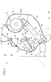
- the vehicle air conditioner 10 includes an air conditioning case 12 constituting air passages, a blower 14 disposed inside the air conditioning case 12, and an evaporator 16 for cooling the air.
- the heater core 18 heats the air, and the damper mechanism 20 switches the flow of the air flowing in the respective passages.
- the left side (arrow A direction) of the vehicle air conditioner 10 shown in FIG. 1 will be referred to as the front side of the vehicle, and the right side (arrow B direction) will be described as the rear side of the vehicle.
- the air conditioning case 12 includes, for example, substantially symmetrical first and second divided cases 22 and 24 and a lower case 26 mounted below the first and second divided cases 22 and 24.
- the first and second divided cases 22 and 24 can be divided in the width direction orthogonal to the longitudinal direction of the vehicle (directions of arrows A and B in FIG. 1), while the lower case 26 is a first divided case. 22 and the second divided case 24 are provided.
- a defroster vent 30 for blowing air in the vicinity is open.
- the vent vent 28 is formed adjacent to the vehicle rear side (arrow B direction) and the defroster vent 30 is on the vehicle front side (arrow A).
- blower 14 is accommodated in the air conditioning case 12 at a position on the upper side (arrow C1 direction) and on the rear side of the vehicle (arrow B direction).
- the blower 14 is provided at, for example, a substantially central portion in the width direction of the air conditioning case 12 so as to straddle between the first divided case 22 and the second divided case 24 and is a drive source comprising a motor etc. 32 and a fan 34 having a plurality of fins on the circumferential surface and connected to the drive shaft of the drive source 32.
- a spiral air passage 36 is formed in the air conditioning case 12 so as to surround the outer peripheral side of the air blower 14, and the air passage 36 is viewed clockwise from the lower side of the air blower 14 as viewed from the first divided case 22 side. It is formed and extends toward the vehicle front side (arrow A direction) while the passage sectional area gradually increases.
- a first passage 38 is formed in the lower case 26 below the air passage 36 (in the direction of arrow C2), and the first passage 38 is gradually inclined downward toward the vehicle front side (the direction of arrow A). And is formed upstream of the evaporator 16. Then, after the air taken in from the outside is circulated in a spiral along the air passage 36 under the driving action of the blower 14, the air is taken to the first passage 38 formed on the lower side of the air conditioning case 12 (arrow C2 direction). It flows and is supplied to the evaporator 16.
- the evaporator 16 is provided, for example, between a pair of first and second tanks 40 and 42 arranged in parallel and supplied / discharged with a refrigerant, the first tank 40 and the second tank 42, and a plurality of evaporators 16 And a first heat exchange unit (heat exchange unit) 44 including the tubes, and the first and second tanks 40 and 42 are connected to both ends of the plurality of tubes.
- the evaporator 16 is inclined at a predetermined angle so that the first tank 40 at the upper end thereof is at the vehicle rear side (arrow B direction) and the second tank 42 at the lower end is on the vehicle front side (arrow A). And the first tank 40 is disposed below the blower 14 (in the direction of the arrow C2).
- the refrigerant circulates from the first tank 40 to the second tank 42 through the plurality of tubes in the first heat exchange unit 44, and the fins provided between the tubes in the first heat exchange unit 44 By passing the air from the one passage 38, heat exchange between the air and the refrigerant is performed, and the cooled air is supplied to the downstream side (the second passage 46 side) of the evaporator 16.
- the air conditioning case 12 is provided with a second passage 46 on the downstream side of the evaporator 16, and an air mix damper 48 that constitutes the damper mechanism 20 is provided in the second passage 46.
- a heater core 18 is provided on the downstream side of the second passage 46 at the vehicle front side (the direction of the arrow A).
- the second passage 46 communicates with the third passage 50 extending to the vent air outlet 28 on the vehicle rear side (the direction of the arrow B), and the second passage 46 and the heater core 18 or the third passage 50 communicate with each other. Is switched by the air mix damper 48.
- the second passage 46 is formed such that a bottom surface (guide surface) 46a on the lower side (direction of arrow C2) is inclined upward from the evaporator 16 side to the heater core 18 side, and is planar Is formed. That is, the bottom surface 46 a of the second passage 46 is formed in a straight line inclined at a predetermined angle such that one end on the evaporator 16 side is downward and the other end on the heater core 18 is upward. In other words, the bottom surface 46 a of the second passage 46 extends substantially orthogonal to the height direction of the evaporator 16.
- One end of the bottom surface 46 a is formed to be substantially flush with the boundary between the second tank 42 of the evaporator 16 and the first heat exchange unit 44, that is, the lower end 44 a of the first heat exchange unit 44. .
- the third passage 50 is formed at a position on the vehicle front side (direction of arrow A) with respect to the blower 14 and moves upward (direction of arrow C1) toward the vent air outlet 28. And extend substantially in a straight line.
- the heater core 18 is provided, for example, between a pair of third and fourth tanks 54 and 56 arranged in parallel and supplied / discharged with hot water, the third tank 54 and the fourth tank 56, And a second heat exchange unit (heat exchange unit) 58 including the tubes, and both ends of the plurality of tubes are connected to the third and fourth tanks 54 and 56, respectively.
- a second heat exchange unit heat exchange unit
- the heater core 18 is inclined at a predetermined angle so that the third tank 54 at the upper end thereof is the vehicle rear side (arrow B direction) and the fourth tank 56 at the lower end is the vehicle front side (arrow A). Are disposed substantially in parallel with the evaporator 16 with the second passage 46 interposed therebetween.
- warm water is circulated from the third tank 54 to the fourth tank 56 through the plurality of tubes in the second heat exchange section 58, and air from the second passage 46 is supplied to the fins provided between the tubes.
- air from the second passage 46 is supplied to the fins provided between the tubes.
- heat exchange between the air and the hot water is performed, and the heated air is supplied to the fourth passage 52 formed on the downstream side of the heater core 18. That is, in the heater core 18, heat is exchanged by the air passing through the second heat exchange unit 58.
- the fourth tank 56 of the heater core 18 is formed so that the boundary (lower end 58a) with the second heat exchange section 58 is substantially flush with the bottom surface 46a of the second passage 46, and the other bottom surface 46a. It is arranged adjacent to the end. In other words, the lower end 58a of the second heat exchanging portion 58 of the heater core 18 and the bottom surface 46a of the second passage 46 are formed to be substantially flush with each other.
- the bottom surface 46 a of the second passage 46 is formed so as to be substantially orthogonal to the evaporator 16 and the heater core 18 which are disposed at an angle.
- the angle between the evaporator 16 and the heater core 18 and the bottom surface 46a is about 90 °.
- the inclination angle ⁇ of the evaporator 16 and the heater core 18 described above is set to be within the range of about 15 ° to 55 ° with respect to the imaginary horizontal plane S.
- the inclination angle ⁇ is, for example, the lower end of the evaporator 16 (the lower end of the first heat exchange unit 44 even when the vehicle equipped with the vehicle air conditioner 10 including the evaporator 16 and the heater core 18 inclines on a steep slope).
- the lower end of the heater core 18 (the lower end 58a of the second heat exchange section 58) does not become lower than in the direction of gravity than in 44a), and the heater core 18 is always above the evaporator 16 in the direction of gravity (arrow C1 direction) It is preset by such an angle that it becomes.
- the bottom surface 46 a of the second passage 46 is formed in a plane that linearly connects the lower end 44 a of the first heat exchange unit 44 in the evaporator 16 and the lower end 58 a of the second heat exchange unit 58 in the heater core 18.
- it may be integrally formed with the air conditioning case 12, or another member may be provided to the air conditioning case 12.
- the damper mechanism 20 includes an air mix damper 48 provided between the evaporator 16 and the heater core 18, a first switching damper 60 for switching the air blowing state of the vent air outlet 28 and the defroster air outlet 30, a third passage 50 and a fourth It has the 2nd switching damper 62 provided between the channel
- the air mix damper 48 is formed, for example, in the shape of a curved plate and is provided along the width direction of the air conditioning case 12, and guide means (not shown) provided on the inner wall surface of the air conditioning case 12 at both sides thereof. Slide along.
- a rack gear 64 is provided on the inner wall surface of the air mix damper 48 along the sliding direction of the air mix damper 48, and the pinion gear of the shaft 66 axially supported by the air conditioning case 12 is engaged.
- seal members 68 a and 68 b are provided at both end portions along the moving direction of the air mix damper 48.
- the air mix damper 48 is slid and displaced in a substantially horizontal direction along the guide means by the rotation of the shaft 66 under the action of an actuator (not shown), and the air mix damper 48 faces the heater core 18 in the second passage 46 (see FIG. 2). It is provided so as to be movable from the reference) to a position facing the third passage 50 (see FIG. 3). Then, by moving the air mix damper 48, the mixing ratio of the air (cold air) cooled by the evaporator 16 and the air (warm air) heated by the heater core 18 is adjusted and the air is blown downstream.
- the seal member 68 a provided at the end thereof is sealed by coming into contact with the bottom surface 46 a of the second passage 46.
- the seal member 68 b is sealed by coming into contact with the inner wall surface of the air conditioning case 12 when it moves to the position facing the rear surface.
- the first switching damper 60 is pivotally supported between the vent air outlet 28 and the defroster air outlet 30, and is rotated about a shaft portion by a predetermined angle under the action of an actuator (not shown), whereby the third passage 50 is formed. And the vent air outlet 28 and the defroster air outlet 30 are switched.
- the second switching damper 62 is formed in a fan shape in cross section, and the shaft portion is axially supported with respect to the first and second divided cases 22 and 24, respectively. By rotating only, the communication state between the fourth passage 52, the third passage 50, and the foot air outlet (not shown) is switched.
- the vehicle air conditioner 10 according to the embodiment of the present invention is basically configured as described above, and next, its operation and effects will be described.
- the blower 14 is driven based on a control signal from a controller (not shown) so that air is sucked into the air conditioning case 12 through the inlet (not shown) and the air swirls along the air passage 36. After flowing downward, heat is exchanged by passing through the evaporator 16 and cooled to a predetermined temperature.
- the air mix damper 48 slides toward the rear side of the vehicle (the direction of arrow B) by a predetermined distance, and the seal member 68 b contacts the inner wall surface of the air conditioning case 12. By being in contact with each other, the communication between the second passage 46 and the third passage 50 is blocked.
- the air blown from the blower 14 is cooled by passing through the first heat exchange section 44 of the evaporator 16, and then flows to the heater core 18 side through the second passage 46.
- the bottom surface 46 a of the second passage 46 is provided in a planar shape so as to connect the lower end 44 a of the first heat exchange unit 44 in the evaporator 16 and the lower end 58 a of the second heat exchange unit 58 in the heater core 18. Air can be smoothly flowed to the heater core 18 side on the downstream side in the second passage 46.
- water contained in the air may be cooled when it passes through the first heat exchange unit 44 and may be attached as condensed water, and the condensed water may be attached to the first heat exchange under the action of gravity. After moving to the second tank 42 side along the portion 44, the air falls into the air conditioning case 12. Under the present circumstances, since the heater core 18 is arrange
- the air flowing through the second passage 46 is heated to a predetermined temperature by passing through the second heat exchange portion 58 of the heater core 18 and flows upward through the fourth passage 52, and then a car from a foot air outlet etc. It is blown into the room.
- the evaporator 16 and the heater core 18 are disposed substantially in parallel and inclined to each other in the air conditioning case 12 constituting the vehicle air conditioner 10, and the second heat exchange in the heater core 18 is performed.
- a lower end 58a of the portion 58 is provided above the lower end 44a of the first heat exchanging portion 44 of the evaporator 16 in the direction of gravity (in the direction of the arrow C1).
- the bottom surface 46 a of the second passage 46 connecting the evaporator 16 and the heater core 18 is constituted by the lower end 44 a of the first heat exchanging portion 44 in the evaporator 16 and the lower end 58 a of the second heat exchanging portion 58 in the heater core 18. It is formed in a straight line to be connected.
- the condensed water attached to the evaporator 16 is moved to the heater core 18 side. Is prevented. Further, with the air mix damper 48 moved to the third passage 50 side (see FIG. 3), the air having passed through the first heat exchanging portion 44 of the evaporator 16 is made along the bottom surface 46 a of the second passage 46. It can be made to distribute
- the blowing resistance of the air can be significantly reduced, Accordingly, the heat exchange efficiency of the heater core 18 can be improved by enabling the air to pass uniformly to the second heat exchange unit 58.
- the conventional plate-like damper can be used.
- the seat portion can be used as the bottom surface 46 a of the second passage 46 by appropriately setting the moving amount of the air mix damper 48. Therefore, by raising the seat portion, the air flow resistance can be smoothly distributed without increasing the air flow resistance, as compared with the vehicle air conditioner according to the related art in which the air flow resistance is increased.
- the slide type air mix damper 48 there is no need to secure a pivoting space which is required when the plate-like damper is pivoted about the rotary shaft, so the evaporator 16 and the heater core 18 are used. It is possible to reduce the separation distance between As a result, space saving in the air conditioning case 12 can be achieved, and the vehicle air conditioner 10 can be miniaturized.
- the seal member 68 a of the air mix damper 48 is provided so as to protrude toward the bottom surface 46 a of the second passage 46.
- the seal member 68a can be reliably abutted against the bottom surface 46a, and the seal member 68a abuts. Since it is not necessary to make the second passage 46 side protrude, it is preferable without increasing the air flow resistance of the air flowing through the second passage 46.
- the vehicle air conditioner 10 including the evaporator 16 and the heater core 18 Even when the mounted vehicle is inclined on a steep slope or the like, the evaporator 16 and the heater core 18 do not become substantially parallel, and the heater core 18 is always above the evaporator 16 in the gravity direction (arrow C1 direction) Will be placed. Therefore, even when the vehicle is inclined on a slope or the like, the condensed water adhering to the evaporator 16 is prevented from moving to the heater core 18 side.
- the vehicle air conditioner according to the present invention is, of course, not limited to the above embodiment, and various configurations can be adopted without departing from the scope of the present invention.
Landscapes
- Physics & Mathematics (AREA)
- Thermal Sciences (AREA)
- Engineering & Computer Science (AREA)
- Mechanical Engineering (AREA)
- Air-Conditioning For Vehicles (AREA)
Abstract
An air conditioning device (10) for a vehicle is configured in such a manner that: an evaporator (16) and a heater core (18) are arranged within an air conditioning case (12) so as to be tilted and substantially parallel to each other; and the heater core (18) is provided above the evaporator (16) in the gravitational direction. A second passage (46) located between the evaporator (16) and the heater core (18) is formed so that the bottom surface (46a) of the second passage (46) connects the lower end (44a) of a first heat exchanger (44) for the evaporator (16) and the lower end (58a) of a second heat exchanger (58) for the heater core (18). Consequently, air which flows through the second passage (46) is smoothly conducted to the heater core (18) side along the bottom surface (46a).
Description
本発明は、車両に搭載され、熱交換器によって温度調整のなされた空気を車室内へと送風して車室内の温度調整を行う車両用空調装置に関する。
The present invention relates to a vehicle air conditioner that is mounted on a vehicle and blows air whose temperature has been adjusted by a heat exchanger into a vehicle compartment to adjust the temperature of the vehicle compartment.
従来から、車両に搭載される車両用空調装置は、例えば、特開2011-57129号公報に開示されるように、送風機によって内外気を空気通路を形成した空調ケースへと取り込み、冷却手段であるエバポレータにより冷却された空気と、加熱手段であるヒータコアにより加熱された空気とをエアミックスドアを駆動させることで前記空調ケース内において所望の混合比率に混合した後、例えば、前記空調ケースに設けられた複数の開口部から送風ダクトを通じて車室内へと送風することで温度の調整が行われる。
Conventionally, as disclosed in JP 2011-57129 A, for example, a vehicle air conditioner mounted on a vehicle takes in inside and outside air with an air blower into an air conditioning case having an air passage, and is a cooling means. After the air cooled by the evaporator and the air heated by the heater core which is the heating means are mixed at a desired mixing ratio in the air conditioning case by driving the air mix door, for example, provided in the air conditioning case The temperature is adjusted by blowing air into the vehicle compartment through the air ducts from the plurality of openings.
上述したエバポレータでは、冷媒の循環する熱交換部を空気が通過する際、空気中に含まれる水分が凝縮水として付着するため、該エバポレータと下流側に配置されたヒータコアとの間には、前記凝縮水のヒータコア側への移動を防止するための突出板が設けられている。この突出板は、空調ケースの底壁から鉛直上方に向かって所定高さで立設しているため、送風等によって凝縮水がエバポレータの下流側に配置されたヒータコア側へと移動することを防止している。また、突出板は、その上端部が温風と冷風とを混合させるエアミックスドアの着座する着座部としても機能している。
In the above-described evaporator, when the air passes through the heat exchange section in which the refrigerant circulates, the water contained in the air adheres as condensed water, so the above-mentioned evaporator may be attached to the heater core disposed downstream. A protruding plate is provided to prevent movement of the condensed water to the heater core side. The projecting plate is erected at a predetermined height vertically upward from the bottom wall of the air conditioning case, so that the condensed water is prevented from moving toward the heater core disposed on the downstream side of the evaporator by air flow or the like. doing. In addition, the projecting plate also functions as a seating portion on which an upper end portion of the air mixing door which mixes hot air and cold air is seated.
しかしながら、上述した車両用空調装置の突出板は、エバポレータからヒータコアへと流れる空気の送風方向と略直交するように立設し、しかも、前記エバポレータの高さ寸法の半分近くまで延在しているため、前記空気が流れる際の送風抵抗が増加してしまうこととなる。
However, the projecting plate of the vehicle air conditioner described above is erected so as to be substantially orthogonal to the blowing direction of the air flowing from the evaporator to the heater core, and extends to nearly half the height dimension of the evaporator. Therefore, the air flow resistance when the air flows will be increased.
また、この突出板は、エアミックスドアが着座するシート部も兼ねているため、一端部に回転軸を有した片持ち式の板状ドアとした場合、前記エアミックスドアを小型化すると、その分だけ着座部である前記突出板の上端部を高くする必要が生じるため、ますます送風抵抗が増加してしまう。
In addition, since the projecting plate also serves as a seat portion on which the air mix door is seated, when the cantilevered plate-like door having the rotation shaft at one end is formed, the air mix door is miniaturized, Since it is necessary to raise the upper end of the projecting plate, which is the seating portion, by a certain amount, the air flow resistance is further increased.
本発明の一般的な目的は、エバポレータの凝縮水がヒータコア側へ移動することを防止しつつ、送風抵抗を低減させ熱交換効率の向上を図ることが可能な車両用空調装置を提供することにある。
A general object of the present invention is to provide a vehicle air conditioner capable of reducing the air flow resistance and improving the heat exchange efficiency while preventing the condensed water of the evaporator from moving to the heater core side. is there.
本発明は、空気の流通する流路を有した空調ケースと、空調ケースの内部に設けられ空気を冷却するエバポレータと、空気を加熱するヒータコアとを有した車両用空調装置において、
空調ケース内において、エバポレータの熱交換部下端よりも重力方向上方にヒータコアの熱交換部下端がくるように配置され、且つ、エバポレータ及びヒータコアが互いに略平行となるようにそれぞれ傾斜して配置され、
エバポレータにおける熱交換部下端とヒータコアにおける熱交換部下端とを直線状に接続するガイド面を備えることを特徴とする。 The present invention relates to a vehicle air conditioner having an air conditioning case having a flow path through which air flows, an evaporator provided inside the air conditioning case for cooling the air, and a heater core for heating the air,
In the air conditioning case, the lower end of the heat exchange portion of the heater core is located above the lower end of the heat exchange portion of the evaporator in the direction of gravity, and the evaporator and the heater core are arranged to be substantially parallel to each other.
A guide surface is provided which linearly connects the lower end of the heat exchange unit in the evaporator and the lower end of the heat exchange unit in the heater core.
本発明によれば、車両用空調装置の空調ケース内に、エバポレータとヒータコアとを略平行且つ互いに傾斜させて配置させると共に、ヒータコアの熱交換部下端をエバポレータの熱交換部下端よりも重力方向上方となるように設け、エバポレータにおける熱交換部下端とヒータコアにおける熱交換部下端とをガイド面によって直線状に接続している。
According to the present invention, the evaporator and the heater core are disposed substantially in parallel and inclined to each other in the air conditioning case of the vehicle air conditioner, and the lower end of the heat exchange portion of the heater core is above the lower end of the heat exchange portion of the evaporator in the gravity direction The lower end of the heat exchange portion in the evaporator and the lower end of the heat exchange portion in the heater core are linearly connected by the guide surface.
従って、ヒータコアの熱交換部下端をエバポレータの熱交換部下端に対して重力方向上方に配置することでエバポレータに付着した凝縮水がヒータコア側へと移動してしまうことが確実に防止され、しかも、エバポレータの熱交換部を通過した空気を、ガイド面に沿ってヒータコアの熱交換部へと円滑に流通させることができる。その結果、エバポレータとヒータコアとの間に送風方向と直交した突出板を設けていた従来技術に係る車両用空調装置と比較し、空気の送風抵抗を大幅に低減させることが可能となり、ヒータコアの熱交換効率を向上させることができる。
Therefore, by disposing the lower end of the heat exchange portion of the heater core upward in the direction of gravity with respect to the lower end of the heat exchange portion of the evaporator, the condensed water attached to the evaporator is reliably prevented from moving to the heater core side. The air having passed through the heat exchange section of the evaporator can be smoothly circulated along the guide surface to the heat exchange section of the heater core. As a result, compared with the vehicle air conditioner according to the related art in which the projecting plate provided perpendicular to the air blowing direction is provided between the evaporator and the heater core, the air blowing resistance can be significantly reduced, and the heat of the heater core can be reduced. Exchange efficiency can be improved.
この車両用空調装置10は、図1に示されるように空気の各通路を構成する空調ケース12と、前記空調ケース12の内部に配設される送風機14と、前記空気を冷却するエバポレータ16と、該空気を加熱するヒータコア18と、前記各通路内を流通する空気の流れを切り換えるダンパ機構20とを含む。なお、以下の説明では、図1に示される車両用空調装置10の左側(矢印A方向)を車両の前方側とし、右側(矢印B方向)を該車両の後方側として説明する。
As shown in FIG. 1, the vehicle air conditioner 10 includes an air conditioning case 12 constituting air passages, a blower 14 disposed inside the air conditioning case 12, and an evaporator 16 for cooling the air. The heater core 18 heats the air, and the damper mechanism 20 switches the flow of the air flowing in the respective passages. In the following description, the left side (arrow A direction) of the vehicle air conditioner 10 shown in FIG. 1 will be referred to as the front side of the vehicle, and the right side (arrow B direction) will be described as the rear side of the vehicle.
空調ケース12は、例えば、略対称形状の第1及び第2分割ケース22、24と、該第1及び第2分割ケース22、24の下部に装着されるロアケース26とから構成される。この第1及び第2分割ケース22、24は、車両の前後方向(図1中、矢印A、B方向)と直交する幅方向に分割可能に設けられ、一方、ロアケース26は、第1分割ケース22から第2分割ケース24に跨るように設けられる。
The air conditioning case 12 includes, for example, substantially symmetrical first and second divided cases 22 and 24 and a lower case 26 mounted below the first and second divided cases 22 and 24. The first and second divided cases 22 and 24 can be divided in the width direction orthogonal to the longitudinal direction of the vehicle (directions of arrows A and B in FIG. 1), while the lower case 26 is a first divided case. 22 and the second divided case 24 are provided.
また、図1に示されるように、空調ケース12の上方(矢印C1方向)には、乗員の顔近傍に送風を行うベント送風口28と、該ベント送風口28と隣接して車両のフロントウィンドウ近傍に送風を行うデフロスタ送風口30とが開口している。なお、ベント送風口28が車両後方側(矢印B方向)、デフロスタ送風口30が車両前方側(矢印A方向)となるように隣接して形成される。
Further, as shown in FIG. 1, a vent air outlet 28 for blowing air near the occupant's face (in the direction of arrow C1) above the air conditioning case 12 and a front window of the vehicle adjacent to the vent air outlet 28. A defroster vent 30 for blowing air in the vicinity is open. The vent vent 28 is formed adjacent to the vehicle rear side (arrow B direction) and the defroster vent 30 is on the vehicle front side (arrow A).
一方、空調ケース12の内部には、上方(矢印C1方向)且つ車両の後方側(矢印B方向)となる位置に送風機14が収納される。
On the other hand, the blower 14 is accommodated in the air conditioning case 12 at a position on the upper side (arrow C1 direction) and on the rear side of the vehicle (arrow B direction).
この送風機14は、例えば、第1分割ケース22と第2分割ケース24との間に跨るように空調ケース12の幅方向略中央に設けられ、通電作用下に回転駆動するモータ等からなる駆動源32と、周面に複数のフィンを有し前記駆動源32の駆動軸に連結されたファン34とからなる。
The blower 14 is provided at, for example, a substantially central portion in the width direction of the air conditioning case 12 so as to straddle between the first divided case 22 and the second divided case 24 and is a drive source comprising a motor etc. 32 and a fan 34 having a plurality of fins on the circumferential surface and connected to the drive shaft of the drive source 32.
そして、空調ケース12には、送風機14の外周側を取り巻くように螺旋状の送風通路36が形成され、該送風通路36は第1分割ケース22側から見て前記送風機14の下方から時計回りに形成され、通路断面積が徐々に大きくなりながら車両前方側(矢印A方向)に向かって延在している。
A spiral air passage 36 is formed in the air conditioning case 12 so as to surround the outer peripheral side of the air blower 14, and the air passage 36 is viewed clockwise from the lower side of the air blower 14 as viewed from the first divided case 22 side. It is formed and extends toward the vehicle front side (arrow A direction) while the passage sectional area gradually increases.
この送風通路36の下方(矢印C2方向)には、ロアケース26の内部に第1通路38が形成され、該第1通路38は車両前方側(矢印A方向)に向かって下方へと徐々に傾斜するように延在すると共に、エバポレータ16の上流側に形成される。そして、送風機14の駆動作用下に外部から取り込まれた空気が送風通路36に沿って螺旋状に流通した後、空調ケース12の下方側(矢印C2方向)に形成された第1通路38へと流通してエバポレータ16へと供給される。
A first passage 38 is formed in the lower case 26 below the air passage 36 (in the direction of arrow C2), and the first passage 38 is gradually inclined downward toward the vehicle front side (the direction of arrow A). And is formed upstream of the evaporator 16. Then, after the air taken in from the outside is circulated in a spiral along the air passage 36 under the driving action of the blower 14, the air is taken to the first passage 38 formed on the lower side of the air conditioning case 12 (arrow C2 direction). It flows and is supplied to the evaporator 16.
エバポレータ16は、例えば、並列に配置され冷媒の供給・排出される一組の第1及び第2タンク40、42と、前記第1タンク40と前記第2タンク42との間に設けられ、複数のチューブを含む第1熱交換部(熱交換部)44とを有し、複数のチューブの両端部に第1及び第2タンク40、42が接続される。
The evaporator 16 is provided, for example, between a pair of first and second tanks 40 and 42 arranged in parallel and supplied / discharged with a refrigerant, the first tank 40 and the second tank 42, and a plurality of evaporators 16 And a first heat exchange unit (heat exchange unit) 44 including the tubes, and the first and second tanks 40 and 42 are connected to both ends of the plurality of tubes.
そして、エバポレータ16は、その上端部となる第1タンク40が車両後方側(矢印B方向)、下端部となる第2タンク42が車両前方側(矢印A方向)となるように所定角度だけ傾斜して配置されると共に、前記第1タンク40が送風機14の下方(矢印C2方向)となるように配置される。
Then, the evaporator 16 is inclined at a predetermined angle so that the first tank 40 at the upper end thereof is at the vehicle rear side (arrow B direction) and the second tank 42 at the lower end is on the vehicle front side (arrow A). And the first tank 40 is disposed below the blower 14 (in the direction of the arrow C2).
このエバポレータ16には、第1タンク40から第1熱交換部44における複数のチューブを通じて第2タンク42へと冷媒が循環し、第1熱交換部44においてチューブの間に設けられたフィンに第1通路38からの空気が通過することで、該空気と前記冷媒との熱交換がなされ、冷却された空気がエバポレータ16の下流側(第2通路46側)へと供給される。
In the evaporator 16, the refrigerant circulates from the first tank 40 to the second tank 42 through the plurality of tubes in the first heat exchange unit 44, and the fins provided between the tubes in the first heat exchange unit 44 By passing the air from the one passage 38, heat exchange between the air and the refrigerant is performed, and the cooled air is supplied to the downstream side (the second passage 46 side) of the evaporator 16.
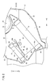
また、図1及び図2に示されるように、空調ケース12にはエバポレータ16の下流側に第2通路46が設けられ、該第2通路46にはダンパ機構20を構成するエアミックスダンパ48が設けられると共に、該第2通路46の下流側には、車両前方側(矢印A方向)においてヒータコア18が設けられる。
Further, as shown in FIGS. 1 and 2, the air conditioning case 12 is provided with a second passage 46 on the downstream side of the evaporator 16, and an air mix damper 48 that constitutes the damper mechanism 20 is provided in the second passage 46. A heater core 18 is provided on the downstream side of the second passage 46 at the vehicle front side (the direction of the arrow A).
そして、第2通路46は、車両後方側(矢印B方向)においてベント送風口28まで延在する第3通路50と連通し、前記第2通路46とヒータコア18又は第3通路50との連通状態をエアミックスダンパ48によって切り替えられる。
The second passage 46 communicates with the third passage 50 extending to the vent air outlet 28 on the vehicle rear side (the direction of the arrow B), and the second passage 46 and the heater core 18 or the third passage 50 communicate with each other. Is switched by the air mix damper 48.
また、第2通路46は、その下方側(矢印C2方向)となる底面(ガイド面)46aがエバポレータ16側からヒータコア18側に向かって上方へ向かうように傾斜して形成され、且つ、平面状に形成される。すなわち、第2通路46の底面46aは、エバポレータ16側となる一端部が下方に、ヒータコア18側となる他端部が上方となるように所定角度傾斜して一直線状に形成されている。換言すれば、第2通路46の底面46aは、エバポレータ16の高さ方向と略直交するように延在している。
Further, the second passage 46 is formed such that a bottom surface (guide surface) 46a on the lower side (direction of arrow C2) is inclined upward from the evaporator 16 side to the heater core 18 side, and is planar Is formed. That is, the bottom surface 46 a of the second passage 46 is formed in a straight line inclined at a predetermined angle such that one end on the evaporator 16 side is downward and the other end on the heater core 18 is upward. In other words, the bottom surface 46 a of the second passage 46 extends substantially orthogonal to the height direction of the evaporator 16.
この底面46aの一端部は、エバポレータ16の第2タンク42と第1熱交換部44との境界、すなわち、前記第1熱交換部44の下端44aと略同一平面となるように形成されている。
One end of the bottom surface 46 a is formed to be substantially flush with the boundary between the second tank 42 of the evaporator 16 and the first heat exchange unit 44, that is, the lower end 44 a of the first heat exchange unit 44. .
一方、第3通路50は、図1に示されるように、送風機14に対して車両前方側(矢印A方向)となる位置に形成され、ベント送風口28に向かって上方(矢印C1方向)へと略一直線上に延在している。
On the other hand, as shown in FIG. 1, the third passage 50 is formed at a position on the vehicle front side (direction of arrow A) with respect to the blower 14 and moves upward (direction of arrow C1) toward the vent air outlet 28. And extend substantially in a straight line.
ヒータコア18は、例えば、並列に配置され温水の供給・排出される一組の第3及び第4タンク54、56と、前記第3タンク54と前記第4タンク56との間に設けられ、複数のチューブを含む第2熱交換部(熱交換部)58とを有し、複数のチューブの両端部が第3及び第4タンク54、56へとそれぞれ接続される。
The heater core 18 is provided, for example, between a pair of third and fourth tanks 54 and 56 arranged in parallel and supplied / discharged with hot water, the third tank 54 and the fourth tank 56, And a second heat exchange unit (heat exchange unit) 58 including the tubes, and both ends of the plurality of tubes are connected to the third and fourth tanks 54 and 56, respectively.
そして、ヒータコア18は、その上端部となる第3タンク54が車両後方側(矢印B方向)、下端部となる第4タンク56が車両前方側(矢印A方向)となるように所定角度だけ傾斜して配置され、第2通路46を挟んでエバポレータ16と略平行に設けられている。
The heater core 18 is inclined at a predetermined angle so that the third tank 54 at the upper end thereof is the vehicle rear side (arrow B direction) and the fourth tank 56 at the lower end is the vehicle front side (arrow A). Are disposed substantially in parallel with the evaporator 16 with the second passage 46 interposed therebetween.
このヒータコア18には、第3タンク54から第2熱交換部58における複数のチューブを通じて第4タンク56へと温水が循環し、前記チューブの間に設けられたフィンに第2通路46からの空気が通過することで、該空気と前記温水との熱交換がなされ、加熱された空気がヒータコア18の下流側に形成された第4通路52へと供給される。すなわち、ヒータコア18は、第2熱交換部58に空気が通過することで熱交換がなされる。
In the heater core 18, warm water is circulated from the third tank 54 to the fourth tank 56 through the plurality of tubes in the second heat exchange section 58, and air from the second passage 46 is supplied to the fins provided between the tubes. As a result, heat exchange between the air and the hot water is performed, and the heated air is supplied to the fourth passage 52 formed on the downstream side of the heater core 18. That is, in the heater core 18, heat is exchanged by the air passing through the second heat exchange unit 58.
そして、ヒータコア18の第4タンク56は、第2熱交換部58との境界(下端58a)が第2通路46の底面46aと略同一平面となるように形成され、且つ、前記底面46aの他端部と隣接するように配置される。換言すれば、ヒータコア18における第2熱交換部58の下端58aと、第2通路46の底面46aとが略同一平面となるように形成されている。
The fourth tank 56 of the heater core 18 is formed so that the boundary (lower end 58a) with the second heat exchange section 58 is substantially flush with the bottom surface 46a of the second passage 46, and the other bottom surface 46a. It is arranged adjacent to the end. In other words, the lower end 58a of the second heat exchanging portion 58 of the heater core 18 and the bottom surface 46a of the second passage 46 are formed to be substantially flush with each other.
すなわち、第2通路46の底面46aは、それぞれ傾斜して配置されたエバポレータ16及びヒータコア18に対して略直交するように形成されている。換言すれば、エバポレータ16及びヒータコア18と底面46aとがなす角度は、それぞれ約90°となる。
That is, the bottom surface 46 a of the second passage 46 is formed so as to be substantially orthogonal to the evaporator 16 and the heater core 18 which are disposed at an angle. In other words, the angle between the evaporator 16 and the heater core 18 and the bottom surface 46a is about 90 °.
また、図1に示されるように、上述したエバポレータ16及びヒータコア18の傾斜角度θは、仮想の水平面Sに対して約15°~55°の範囲内となるように設定される。この傾斜角度θは、例えば、前記エバポレータ16及びヒータコア18を含む車両用空調装置10の搭載された車両が、急坂路等で傾斜した場合でも前記エバポレータ16の下端(第1熱交換部44の下端44a)よりも前記ヒータコア18の下端(第2熱交換部58の下端58a)が重力方向下側となることがなく、常に前記ヒータコア18が前記エバポレータ16に対して重力方向上方(矢印C1方向)となるような角度で予め設定されている。
Further, as shown in FIG. 1, the inclination angle θ of the evaporator 16 and the heater core 18 described above is set to be within the range of about 15 ° to 55 ° with respect to the imaginary horizontal plane S. The inclination angle θ is, for example, the lower end of the evaporator 16 (the lower end of the first heat exchange unit 44 even when the vehicle equipped with the vehicle air conditioner 10 including the evaporator 16 and the heater core 18 inclines on a steep slope). The lower end of the heater core 18 (the lower end 58a of the second heat exchange section 58) does not become lower than in the direction of gravity than in 44a), and the heater core 18 is always above the evaporator 16 in the direction of gravity (arrow C1 direction) It is preset by such an angle that it becomes.
なお、第2通路46の底面46aは、エバポレータ16における第1熱交換部44の下端44aとヒータコア18における第2熱交換部58の下端58aとを直線的に結ぶ平面状に形成されていればよく、例えば、空調ケース12と一体的に形成されていてもよいし、前記空調ケース12に対して別部材を設けるようにしてもよい。
The bottom surface 46 a of the second passage 46 is formed in a plane that linearly connects the lower end 44 a of the first heat exchange unit 44 in the evaporator 16 and the lower end 58 a of the second heat exchange unit 58 in the heater core 18. For example, it may be integrally formed with the air conditioning case 12, or another member may be provided to the air conditioning case 12.
ダンパ機構20は、エバポレータ16とヒータコア18との間に設けられるエアミックスダンパ48と、ベント送風口28及びデフロスタ送風口30の送風状態を切り替える第1切替ダンパ60と、第3通路50と第4通路52との間に設けられデフロスタ送風口30及びフット送風口の送風状態を切り替える第2切替ダンパ62とを有する。
The damper mechanism 20 includes an air mix damper 48 provided between the evaporator 16 and the heater core 18, a first switching damper 60 for switching the air blowing state of the vent air outlet 28 and the defroster air outlet 30, a third passage 50 and a fourth It has the 2nd switching damper 62 provided between the channel | path 52 and switching the ventilation state of the defroster ventilation port 30 and a foot ventilation port.
エアミックスダンパ48は、例えば、湾曲したプレート状に形成され、空調ケース12の幅方向に沿って設けられ、その両側部が前記空調ケース12の内壁面に設けられたガイド手段(図示せず)に沿ってスライド変位する。そして、エアミックスダンパ48の内壁面には、該エアミックスダンパ48のスライド方向に沿ってラックギア64が設けられ、空調ケース12に軸支されたシャフト66のピニオンギアが噛合される。
The air mix damper 48 is formed, for example, in the shape of a curved plate and is provided along the width direction of the air conditioning case 12, and guide means (not shown) provided on the inner wall surface of the air conditioning case 12 at both sides thereof. Slide along. A rack gear 64 is provided on the inner wall surface of the air mix damper 48 along the sliding direction of the air mix damper 48, and the pinion gear of the shaft 66 axially supported by the air conditioning case 12 is engaged.
また、エアミックスダンパ48の移動方向に沿った両端部には、それぞれシール部材68a、68bが設けられる。
Further, seal members 68 a and 68 b are provided at both end portions along the moving direction of the air mix damper 48.
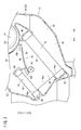
このエアミックスダンパ48は、図示しないアクチュエータの駆動作用下にシャフト66が回転することで、ガイド手段に沿って略水平方向にスライド変位し、第2通路46内においてヒータコア18に臨む位置(図2参照)から第3通路50に臨む位置(図3参照)まで移動可能に設けられる。そして、エアミックスダンパ48が移動することで、エバポレータ16によって冷却された空気(冷風)と、ヒータコア18によって加熱された空気(温風)との混合比率を調整して下流側へと送風する。
The air mix damper 48 is slid and displaced in a substantially horizontal direction along the guide means by the rotation of the shaft 66 under the action of an actuator (not shown), and the air mix damper 48 faces the heater core 18 in the second passage 46 (see FIG. 2). It is provided so as to be movable from the reference) to a position facing the third passage 50 (see FIG. 3). Then, by moving the air mix damper 48, the mixing ratio of the air (cold air) cooled by the evaporator 16 and the air (warm air) heated by the heater core 18 is adjusted and the air is blown downstream.
また、エアミックスダンパ48は、ヒータコア18に臨む位置まで移動した際、その端部に設けられたシール部材68aが第2通路46の底面46aに当接することでシールされ、一方、第3通路50に臨む位置まで移動した際、シール部材68bが空調ケース12の内壁面に当接することでシールされる。
Further, when the air mix damper 48 is moved to a position facing the heater core 18, the seal member 68 a provided at the end thereof is sealed by coming into contact with the bottom surface 46 a of the second passage 46. The seal member 68 b is sealed by coming into contact with the inner wall surface of the air conditioning case 12 when it moves to the position facing the rear surface.
第1切替ダンパ60は、ベント送風口28とデフロスタ送風口30との間に軸支され、図示しないアクチュエータの駆動作用下に軸部を中心として所定角度だけ回動することで、第3通路50とベント送風口28及びデフロスタ送風口30との連通状態を切り替えている。
The first switching damper 60 is pivotally supported between the vent air outlet 28 and the defroster air outlet 30, and is rotated about a shaft portion by a predetermined angle under the action of an actuator (not shown), whereby the third passage 50 is formed. And the vent air outlet 28 and the defroster air outlet 30 are switched.
第2切替ダンパ62は、断面扇形状に形成され軸部が第1及び第2分割ケース22、24に対してそれぞれ軸支され、図示しないアクチュエータの駆動作用下に前記軸部を中心として所定角度だけ回動することで、第4通路52と第3通路50及びフット送風口(図示せず)との連通状態を切り替えている。
The second switching damper 62 is formed in a fan shape in cross section, and the shaft portion is axially supported with respect to the first and second divided cases 22 and 24, respectively. By rotating only, the communication state between the fourth passage 52, the third passage 50, and the foot air outlet (not shown) is switched.
本発明の実施の形態に係る車両用空調装置10は、基本的には以上のように構成されるものであり、次にその動作並びに作用効果について説明する。
The vehicle air conditioner 10 according to the embodiment of the present invention is basically configured as described above, and next, its operation and effects will be described.
先ず、車室内の室温を低下させる冷房運転を行う場合について説明する。図示しない乗員が車室内において操作レバーを操作して冷房運転を選択することで、該操作レバーの操作に応じて図示しないアクチュエータが駆動してエアミックスダンパ48がガイド手段による案内作用下に車両前方側(矢印A方向)へと所定距離だけスライドし、そのシール部材68aが底面46aへと当接する。これにより、図1に示されるように、空調ケース12内において第2通路46と第3通路50とが連通し、前記第2通路46とヒータコア18との連通が遮断された状態となる。
First, the case of performing the cooling operation to lower the room temperature in the vehicle compartment will be described. When a passenger (not shown) operates the operation lever in the vehicle compartment to select the cooling operation, an actuator (not shown) is driven according to the operation of the operation lever to cause the air mix damper 48 to guide the vehicle in front of the vehicle. It slides to the side (the direction of arrow A) by a predetermined distance, and the seal member 68a abuts on the bottom surface 46a. As a result, as shown in FIG. 1, the second passage 46 and the third passage 50 communicate with each other in the air conditioning case 12, and the communication between the second passage 46 and the heater core 18 is cut off.
また、同時に、図示しないコントローラからの制御信号に基づき、送風機14が駆動することで、図示しない導入口を通じて空調ケース12内へ空気が吸い込まれ、該空気が送風通路36に沿って旋回するように下方へと流通した後、エバポレータ16を通過することで熱交換が行われて所定温度に冷却される。
At the same time, the blower 14 is driven based on a control signal from a controller (not shown) so that air is sucked into the air conditioning case 12 through the inlet (not shown) and the air swirls along the air passage 36. After flowing downward, heat is exchanged by passing through the evaporator 16 and cooled to a predetermined temperature.
そして、冷却された空気は、第2通路46から第3通路50へと上方に向かって流通した後、第1切替ダンパ60の切替作用下に開口しているベント送風口28を通じて車室内へと供給される。
Then, after the cooled air circulates upward from the second passage 46 to the third passage 50, the vented air vent 28 opened under the switching action of the first switching damper 60 enters the vehicle compartment. Supplied.
次に、車室内の室温を上昇させる暖房運転を選択し車室内へ温風を送風する場合について説明する。
Next, the case where the heating operation for raising the room temperature in the vehicle compartment is selected and the warm air is blown to the vehicle compartment will be described.
先ず、図示しない操作レバーを操作して暖房運転を選択することで、エアミックスダンパ48が車両後方側(矢印B方向)へと所定距離だけスライドし、シール部材68bが空調ケース12の内壁面に当接することで、第2通路46と第3通路50との連通が遮断された状態となる。
First, by operating the operation lever (not shown) to select the heating operation, the air mix damper 48 slides toward the rear side of the vehicle (the direction of arrow B) by a predetermined distance, and the seal member 68 b contacts the inner wall surface of the air conditioning case 12. By being in contact with each other, the communication between the second passage 46 and the third passage 50 is blocked.
そして、送風機14から送風された空気がエバポレータ16の第1熱交換部44を通過することで冷却された後、第2通路46を通じてヒータコア18側へと流通する。この際、第2通路46の底面46aが、エバポレータ16における第1熱交換部44の下端44aとヒータコア18における第2熱交換部58の下端58aとを繋ぐように平面状に設けられているため、前記第2通路46において空気を円滑に下流側となる前記ヒータコア18側へと流すことができる。
Then, the air blown from the blower 14 is cooled by passing through the first heat exchange section 44 of the evaporator 16, and then flows to the heater core 18 side through the second passage 46. At this time, the bottom surface 46 a of the second passage 46 is provided in a planar shape so as to connect the lower end 44 a of the first heat exchange unit 44 in the evaporator 16 and the lower end 58 a of the second heat exchange unit 58 in the heater core 18. Air can be smoothly flowed to the heater core 18 side on the downstream side in the second passage 46.
また、エバポレータ16には、空気中に含まれた水分が第1熱交換部44を通過する際に冷やされ凝縮水として付着することがあり、該凝縮水は重力作用下に前記第1熱交換部44に沿って第2タンク42側へと移動した後、空調ケース12内へと落下する。この際、エバポレータ16に対してヒータコア18が重力方向上方(矢印C1方向)に配置されているため、凝縮水が前記ヒータコア18側へと移動してしまうことが防止される。
In the evaporator 16, water contained in the air may be cooled when it passes through the first heat exchange unit 44 and may be attached as condensed water, and the condensed water may be attached to the first heat exchange under the action of gravity. After moving to the second tank 42 side along the portion 44, the air falls into the air conditioning case 12. Under the present circumstances, since the heater core 18 is arrange | positioned with respect to the evaporator 16 at the gravity direction upper direction (arrow C 1 direction), it is prevented that condensed water moves to the said heater core 18 side.
そして、第2通路46を流れる空気がヒータコア18の第2熱交換部58を通過することで所定温度に加熱され第4通路52を通じて上方に向かって流れた後、図示しないフット送風口等から車室内へと送風される。
Then, the air flowing through the second passage 46 is heated to a predetermined temperature by passing through the second heat exchange portion 58 of the heater core 18 and flows upward through the fourth passage 52, and then a car from a foot air outlet etc. It is blown into the room.
以上のように、本実施の形態では、車両用空調装置10を構成する空調ケース12において、エバポレータ16とヒータコア18とを略平行且つ互いに傾斜させて配置すると共に、前記ヒータコア18における第2熱交換部58の下端58aを前記エバポレータ16における第1熱交換部44の下端44aに対して重力方向上方(矢印C1方向)となるように設けている。また、エバポレータ16とヒータコア18とを接続する第2通路46の底面46aを、該エバポレータ16における第1熱交換部44の下端44aと、該ヒータコア18における第2熱交換部58の下端58aとを結ぶように直線状に形成している。
As described above, in the present embodiment, the evaporator 16 and the heater core 18 are disposed substantially in parallel and inclined to each other in the air conditioning case 12 constituting the vehicle air conditioner 10, and the second heat exchange in the heater core 18 is performed. A lower end 58a of the portion 58 is provided above the lower end 44a of the first heat exchanging portion 44 of the evaporator 16 in the direction of gravity (in the direction of the arrow C1). Further, the bottom surface 46 a of the second passage 46 connecting the evaporator 16 and the heater core 18 is constituted by the lower end 44 a of the first heat exchanging portion 44 in the evaporator 16 and the lower end 58 a of the second heat exchanging portion 58 in the heater core 18. It is formed in a straight line to be connected.
その結果、ヒータコア18をエバポレータ16に対して重力方向に沿った上方(矢印C1方向)となるように配置することで、該エバポレータ16に付着した凝縮水が前記ヒータコア18側へと移動してしまうことが防止される。また、エアミックスダンパ48が第3通路50側へと移動した状態(図3参照)において、エバポレータ16の第1熱交換部44を通過した空気を、第2通路46の底面46aに沿ってヒータコア18の第2熱交換部58側へと円滑に流通させることができる。
As a result, by arranging the heater core 18 above (in the direction of the arrow C1) along the gravity direction with respect to the evaporator 16, the condensed water attached to the evaporator 16 is moved to the heater core 18 side. Is prevented. Further, with the air mix damper 48 moved to the third passage 50 side (see FIG. 3), the air having passed through the first heat exchanging portion 44 of the evaporator 16 is made along the bottom surface 46 a of the second passage 46. It can be made to distribute | circulate smoothly to the 18th 2nd heat exchange part 58 side.
そのため、エバポレータ16とヒータコア18との間に送風方向と直交した突出板を設けていた従来技術に係る車両用空調装置と比較し、前記空気の送風抵抗を大幅に低減させることが可能となり、それに伴って、第2熱交換部58に対して均一に空気を通過させることを可能とすることで、ヒータコア18における熱交換効率を向上させることができる。
Therefore, compared with the vehicle air conditioner according to the prior art in which the projecting plate perpendicular to the blowing direction is provided between the evaporator 16 and the heater core 18, the blowing resistance of the air can be significantly reduced, Accordingly, the heat exchange efficiency of the heater core 18 can be improved by enabling the air to pass uniformly to the second heat exchange unit 58.
また、エバポレータ16とヒータコア18との間に設けられるエアミックスダンパ48をスライド式とすることで、第2通路46側に臨むヒータコア18の開口部を大きく確保した場合でも、従来の板状ダンパを採用した車両用空調装置と異なり、前記エアミックスダンパ48の移動量を適宜設定することで、シート部を第2通路46の底面46aとすることができる。そのため、シート部を高くすることで送風抵抗が増加していた従来技術に係る車両用空調装置と比較し、前記送風抵抗を増加させることなく円滑に流通させることができる。
In addition, by making the air mix damper 48 provided between the evaporator 16 and the heater core 18 slide, even when the opening of the heater core 18 facing the second passage 46 is largely secured, the conventional plate-like damper can be used. Unlike the adopted vehicle air conditioner, the seat portion can be used as the bottom surface 46 a of the second passage 46 by appropriately setting the moving amount of the air mix damper 48. Therefore, by raising the seat portion, the air flow resistance can be smoothly distributed without increasing the air flow resistance, as compared with the vehicle air conditioner according to the related art in which the air flow resistance is increased.
さらに、スライド式のエアミックスダンパ48を用いることで、板状のダンパを回転軸を支点として回動させる際に必要とされていた回動スペースを確保する必要がないため、エバポレータ16とヒータコア18との間の離間距離を小さくすることが可能となる。その結果、空調ケース12における省スペース化を図ることができ、車両用空調装置10の小型化が可能となる。
Further, by using the slide type air mix damper 48, there is no need to secure a pivoting space which is required when the plate-like damper is pivoted about the rotary shaft, so the evaporator 16 and the heater core 18 are used. It is possible to reduce the separation distance between As a result, space saving in the air conditioning case 12 can be achieved, and the vehicle air conditioner 10 can be miniaturized.
さらにまた、エアミックスダンパ48のシール部材68aを、第2通路46の底面46a側へ突出させるように設けている。これにより、第2通路46の連通を遮断させるためにエアミックスダンパ48をスライドさせた際、シール部材68aを確実に底面46aへと当接させることができ、しかも、前記シール部材68aの当接する第2通路46側を突出させる必要がないため、前記第2通路46を流れる空気の送風抵抗を増加させることがなく好適である。
Furthermore, the seal member 68 a of the air mix damper 48 is provided so as to protrude toward the bottom surface 46 a of the second passage 46. Thus, when the air mix damper 48 is slid to block the communication of the second passage 46, the seal member 68a can be reliably abutted against the bottom surface 46a, and the seal member 68a abuts. Since it is not necessary to make the second passage 46 side protrude, it is preferable without increasing the air flow resistance of the air flowing through the second passage 46.
またさらに、エバポレータ16及びヒータコア18を、仮想の水平面Sに対して約15°~55°の範囲内で傾斜させ配置することで、例えば、前記エバポレータ16及びヒータコア18を含む車両用空調装置10の搭載された車両が、急坂路等で傾斜した場合でも前記エバポレータ16と前記ヒータコア18とが略平行となることがなく、常に前記ヒータコア18が前記エバポレータ16に対して重力方向上方(矢印C1方向)に配置される。そのため、車両が坂路等で傾斜した場合でもエバポレータ16に付着した凝縮水がヒータコア18側へと移動してしまうことが阻止される。
Furthermore, by arranging the evaporator 16 and the heater core 18 at an angle of about 15 ° to 55 ° with respect to the imaginary horizontal plane S, for example, the vehicle air conditioner 10 including the evaporator 16 and the heater core 18 Even when the mounted vehicle is inclined on a steep slope or the like, the evaporator 16 and the heater core 18 do not become substantially parallel, and the heater core 18 is always above the evaporator 16 in the gravity direction (arrow C1 direction) Will be placed. Therefore, even when the vehicle is inclined on a slope or the like, the condensed water adhering to the evaporator 16 is prevented from moving to the heater core 18 side.
なお、本発明に係る車両用空調装置は、上述の実施の形態に限らず、本発明の要旨を逸脱することなく、種々の構成を採り得ることはもちろんである。
The vehicle air conditioner according to the present invention is, of course, not limited to the above embodiment, and various configurations can be adopted without departing from the scope of the present invention.
Claims (4)
- 空気の流通する流路を有した空調ケース(12)と、前記空調ケース(12)の内部に設けられ前記空気を冷却するエバポレータ(16)と、前記空気を加熱するヒータコア(18)とを有した車両用空調装置において、
前記空調ケース(12)内において、前記エバポレータ(16)の熱交換部下端(44a)よりも重力方向上方に前記ヒータコア(18)の熱交換部下端(58a)がくるように配置され、且つ、前記エバポレータ(16)及び前記ヒータコア(18)が互いに略平行となるようにそれぞれ傾斜して配置され、
前記エバポレータ(16)における熱交換部下端(44a)と前記ヒータコア(18)における熱交換部下端(58a)とを直線状に接続するガイド面(46a)を備えることを特徴とする車両用空調装置。 There is an air conditioning case (12) having a flow path through which air flows, an evaporator (16) provided inside the air conditioning case (12) for cooling the air, and a heater core (18) for heating the air. In the vehicle air conditioner,
In the air conditioning case (12), the heat exchange lower end (58a) of the heater core (18) is disposed above the heat exchange lower end (44a) of the evaporator (16) in the gravity direction, and The evaporator (16) and the heater core (18) are arranged in an inclined manner so as to be substantially parallel to each other,
A vehicle air conditioner comprising a guide surface (46a) linearly connecting a heat exchange lower end (44a) of the evaporator (16) and a heat exchange lower end (58a) of the heater core (18). . - 請求項1記載の車両用空調装置において、
前記エバポレータ(16)と前記ヒータコア(18)との間には、スライド変位することで該エバポレータ(16)と該ヒータコア(18)との連通を遮断可能なスライドダンパ(48)が配置されることを特徴とする車両用空調装置。 In the vehicle air conditioner according to claim 1,
Between the evaporator (16) and the heater core (18), a slide damper (48) capable of blocking communication between the evaporator (16) and the heater core (18) by sliding displacement is disposed. A vehicle air conditioner characterized by - 請求項2記載の車両用空調装置において、
前記スライドダンパ(48)のシール部(68a)は、前記エバポレータ(16)と前記ヒータコア(18)との連通を遮断する際、前記ガイド面(46a)に当接することを特徴とする車両用空調装置。 In the vehicle air conditioner according to claim 2,
A vehicle air conditioner characterized in that the seal portion (68a) of the slide damper (48) abuts on the guide surface (46a) when blocking communication between the evaporator (16) and the heater core (18). apparatus. - 請求項1~3のいずれか1項に記載の車両用空調装置において、
前記エバポレータ(16)及び前記ヒータコア(18)は、前記車両用空調装置(10)が車両に搭載された状態で、水平面(S)に対して15°~55°の範囲内となるように傾斜して配置されることを特徴とする車両用空調装置。 The vehicle air conditioner according to any one of claims 1 to 3.
The evaporator (16) and the heater core (18) are inclined to be within a range of 15 ° to 55 ° with respect to the horizontal surface (S) in a state where the vehicle air conditioner (10) is mounted on a vehicle A vehicle air conditioner characterized by being disposed.
Priority Applications (1)
| Application Number | Priority Date | Filing Date | Title |
|---|---|---|---|
| CN201580032182.3A CN106457966B (en) | 2014-06-19 | 2015-06-10 | Air conditioner for vehicles |
Applications Claiming Priority (2)
| Application Number | Priority Date | Filing Date | Title |
|---|---|---|---|
| JP2014-125958 | 2014-06-19 | ||
| JP2014125958A JP2016002949A (en) | 2014-06-19 | 2014-06-19 | Air conditioner for vehicle |
Publications (1)
| Publication Number | Publication Date |
|---|---|
| WO2015194437A1 true WO2015194437A1 (en) | 2015-12-23 |
Family
ID=54935424
Family Applications (1)
| Application Number | Title | Priority Date | Filing Date |
|---|---|---|---|
| PCT/JP2015/066762 WO2015194437A1 (en) | 2014-06-19 | 2015-06-10 | Air conditioning device for vehicle |
Country Status (3)
| Country | Link |
|---|---|
| JP (1) | JP2016002949A (en) |
| CN (1) | CN106457966B (en) |
| WO (1) | WO2015194437A1 (en) |
Cited By (1)
| Publication number | Priority date | Publication date | Assignee | Title |
|---|---|---|---|---|
| CN109476206A (en) * | 2016-08-01 | 2019-03-15 | 大众汽车有限公司 | Conditioner for motor vehicle |
Families Citing this family (4)
| Publication number | Priority date | Publication date | Assignee | Title |
|---|---|---|---|---|
| JP2018144715A (en) * | 2017-03-08 | 2018-09-20 | 株式会社ケーヒン | Vehicular air conditioner |
| JP6420517B1 (en) * | 2018-06-04 | 2018-11-07 | 三菱重工サーマルシステムズ株式会社 | Air conditioner for vehicles |
| WO2020161439A1 (en) * | 2019-02-07 | 2020-08-13 | Valeo Systemes Thermiques | Heating, ventilation and/or air-conditioning device for a motor vehicle |
| CN115164283B (en) * | 2022-06-28 | 2023-08-22 | 三一重机有限公司 | Engineering machinery air conditioning unit and engineering machinery |
Citations (3)
| Publication number | Priority date | Publication date | Assignee | Title |
|---|---|---|---|---|
| JP2002211225A (en) * | 2001-01-16 | 2002-07-31 | Mitsubishi Heavy Ind Ltd | Air conditioner for vehicle |
| JP2008062803A (en) * | 2006-09-07 | 2008-03-21 | Denso Corp | Vehicular air conditioner |
| JP2009023590A (en) * | 2007-07-23 | 2009-02-05 | Denso Corp | Air conditioner |
Family Cites Families (3)
| Publication number | Priority date | Publication date | Assignee | Title |
|---|---|---|---|---|
| JP2009286363A (en) * | 2008-05-30 | 2009-12-10 | Denso Corp | Air conditioner for vehicle |
| US9649907B2 (en) * | 2012-04-26 | 2017-05-16 | Honda Motor Co., Ltd. | Vehicle air-conditioner |
| JP6373644B2 (en) * | 2014-05-29 | 2018-08-15 | 株式会社ケーヒン | Air conditioner for vehicles |
-
2014
- 2014-06-19 JP JP2014125958A patent/JP2016002949A/en active Pending
-
2015
- 2015-06-10 WO PCT/JP2015/066762 patent/WO2015194437A1/en active Application Filing
- 2015-06-10 CN CN201580032182.3A patent/CN106457966B/en not_active Expired - Fee Related
Patent Citations (3)
| Publication number | Priority date | Publication date | Assignee | Title |
|---|---|---|---|---|
| JP2002211225A (en) * | 2001-01-16 | 2002-07-31 | Mitsubishi Heavy Ind Ltd | Air conditioner for vehicle |
| JP2008062803A (en) * | 2006-09-07 | 2008-03-21 | Denso Corp | Vehicular air conditioner |
| JP2009023590A (en) * | 2007-07-23 | 2009-02-05 | Denso Corp | Air conditioner |
Cited By (1)
| Publication number | Priority date | Publication date | Assignee | Title |
|---|---|---|---|---|
| CN109476206A (en) * | 2016-08-01 | 2019-03-15 | 大众汽车有限公司 | Conditioner for motor vehicle |
Also Published As
| Publication number | Publication date |
|---|---|
| CN106457966A (en) | 2017-02-22 |
| CN106457966B (en) | 2019-11-26 |
| JP2016002949A (en) | 2016-01-12 |
Similar Documents
| Publication | Publication Date | Title |
|---|---|---|
| WO2015194437A1 (en) | Air conditioning device for vehicle | |
| JP4286244B2 (en) | Air conditioner for vehicles | |
| JP2017094753A (en) | Vehicular air conditioning unit | |
| JP2009202687A (en) | Vehicular air conditioner | |
| WO2015146059A1 (en) | Air conditioning unit for vehicle | |
| JP7321016B2 (en) | vehicle air conditioner | |
| EP3363665B1 (en) | Air conditioning device for vehicle | |
| JP7090045B2 (en) | Vehicle air conditioner | |
| JP5353665B2 (en) | Air conditioner for vehicles | |
| JP2014100950A (en) | Air conditioning device for vehicle | |
| WO2015182498A1 (en) | Vehicle air conditioning device | |
| JP2018020650A (en) | Vehicular air conditioner | |
| JP6420531B2 (en) | Air conditioner for vehicles | |
| WO2018211875A1 (en) | Vehicular air conditioning apparatus | |
| JP6329404B2 (en) | Air conditioner for vehicles | |
| JP2005219574A (en) | Vehicular air-conditioner | |
| JP2019177742A (en) | Vehicular air-conditioner | |
| JP4111143B2 (en) | Air conditioner for vehicles | |
| JP2018039397A (en) | Vehicular air conditioner | |
| JP2021079889A (en) | Air conditioner for vehicle | |
| JP4134207B2 (en) | Air conditioner for automobile | |
| KR102533416B1 (en) | Air conditioner for vehicle | |
| JP2017177833A (en) | Air-conditioner for vehicle | |
| JP6029946B2 (en) | Air conditioner for vehicles | |
| JP2016088290A (en) | Vehicular air conditioner |
Legal Events
| Date | Code | Title | Description |
|---|---|---|---|
| 121 | Ep: the epo has been informed by wipo that ep was designated in this application |
Ref document number: 15810032 Country of ref document: EP Kind code of ref document: A1 |
|
| NENP | Non-entry into the national phase |
Ref country code: DE |
|
| 122 | Ep: pct application non-entry in european phase |
Ref document number: 15810032 Country of ref document: EP Kind code of ref document: A1 |