WO2015190020A1 - ケーブルおよび電力供給装置 - Google Patents
ケーブルおよび電力供給装置 Download PDFInfo
- Publication number
- WO2015190020A1 WO2015190020A1 PCT/JP2015/001599 JP2015001599W WO2015190020A1 WO 2015190020 A1 WO2015190020 A1 WO 2015190020A1 JP 2015001599 W JP2015001599 W JP 2015001599W WO 2015190020 A1 WO2015190020 A1 WO 2015190020A1
- Authority
- WO
- WIPO (PCT)
- Prior art keywords
- cable
- power supply
- connector
- line
- conductive member
- Prior art date
Links
Images


Classifications
-
- H—ELECTRICITY
- H01—ELECTRIC ELEMENTS
- H01R—ELECTRICALLY-CONDUCTIVE CONNECTIONS; STRUCTURAL ASSOCIATIONS OF A PLURALITY OF MUTUALLY-INSULATED ELECTRICAL CONNECTING ELEMENTS; COUPLING DEVICES; CURRENT COLLECTORS
- H01R13/00—Details of coupling devices of the kinds covered by groups H01R12/70 or H01R24/00 - H01R33/00
- H01R13/66—Structural association with built-in electrical component
- H01R13/70—Structural association with built-in electrical component with built-in switch
- H01R13/713—Structural association with built-in electrical component with built-in switch the switch being a safety switch
- H01R13/7137—Structural association with built-in electrical component with built-in switch the switch being a safety switch with thermal interrupter
-
- H—ELECTRICITY
- H01—ELECTRIC ELEMENTS
- H01B—CABLES; CONDUCTORS; INSULATORS; SELECTION OF MATERIALS FOR THEIR CONDUCTIVE, INSULATING OR DIELECTRIC PROPERTIES
- H01B11/00—Communication cables or conductors
-
- H—ELECTRICITY
- H01—ELECTRIC ELEMENTS
- H01R—ELECTRICALLY-CONDUCTIVE CONNECTIONS; STRUCTURAL ASSOCIATIONS OF A PLURALITY OF MUTUALLY-INSULATED ELECTRICAL CONNECTING ELEMENTS; COUPLING DEVICES; CURRENT COLLECTORS
- H01R13/00—Details of coupling devices of the kinds covered by groups H01R12/70 or H01R24/00 - H01R33/00
- H01R13/66—Structural association with built-in electrical component
- H01R13/665—Structural association with built-in electrical component with built-in electronic circuit
- H01R13/6683—Structural association with built-in electrical component with built-in electronic circuit with built-in sensor
-
- H—ELECTRICITY
- H01—ELECTRIC ELEMENTS
- H01R—ELECTRICALLY-CONDUCTIVE CONNECTIONS; STRUCTURAL ASSOCIATIONS OF A PLURALITY OF MUTUALLY-INSULATED ELECTRICAL CONNECTING ELEMENTS; COUPLING DEVICES; CURRENT COLLECTORS
- H01R24/00—Two-part coupling devices, or either of their cooperating parts, characterised by their overall structure
- H01R24/60—Contacts spaced along planar side wall transverse to longitudinal axis of engagement
- H01R24/62—Sliding engagements with one side only, e.g. modular jack coupling devices
- H01R24/64—Sliding engagements with one side only, e.g. modular jack coupling devices for high frequency, e.g. RJ 45
-
- H—ELECTRICITY
- H01—ELECTRIC ELEMENTS
- H01R—ELECTRICALLY-CONDUCTIVE CONNECTIONS; STRUCTURAL ASSOCIATIONS OF A PLURALITY OF MUTUALLY-INSULATED ELECTRICAL CONNECTING ELEMENTS; COUPLING DEVICES; CURRENT COLLECTORS
- H01R2107/00—Four or more poles
Definitions
- This technology relates to cables and power supply devices.
- Cables such as USB cables are used for transmitting and receiving data between electronic devices.
- power is supplied from a device on the host side to the device via a USB cable or the like.
- power is supplied to an electronic device from a power supply device such as a USB charging compatible AC adapter via a cable such as a USB cable connected to the power supply device.
- Patent Document 1 proposes a technique for turning off the power and preventing a failure of the apparatus when an abnormal temperature rise occurs.
- an object of the present technology is to provide a cable and a power supply device that can protect at least the cable when an abnormal temperature rise occurs.
- the present technology provides a cable unit including a power supply line constituting a power supply line, a connector provided at at least one of one end and the other end of the cable unit, a temperature detection element, and And a circuit board having a protection circuit including a switch that receives a detection result of the temperature detection element and performs an operation of switching between conduction and interruption of the power supply line.
- a power supply line constituting a power supply line, a connector provided at at least one of the one end and the other end of the cable part, a power supply line, a shape change accompanying a temperature change, And a conductive member that switches between conduction and interruption of the line.
- a cable portion including a power supply line constituting a power supply line, a connector provided at at least one of the one end and the other end of the cable portion, and a + power supply line and a ⁇ It is a cable provided with the electrically-conductive member which short-circuits a power supply line.
- the present technology is a power supply device including a power supply source and at least one of the above-described cables connected to the power supply source.
- This technology can protect at least the cable when an abnormal temperature rise occurs.
- FIG. 1 is a schematic diagram illustrating a configuration example of a cable according to the first embodiment of the present technology.
- FIG. 2 is a schematic diagram showing an outline of the configuration of the connector provided at one end of the cable portion.
- FIG. 3 is a schematic diagram showing an outline of the electrical configuration of the cable.
- FIG. 4 is a schematic diagram showing a specific configuration of the protection circuit.
- FIG. 5 is a schematic diagram showing an outline of the configuration of the cable of Modification 1-1.
- FIG. 6 is a schematic diagram showing a first example of another configuration of the protection circuit.
- FIG. 7 is a schematic diagram showing a second example of another configuration of the protection circuit.
- 8A and 8B are schematic views showing an outline of the configuration of the connector.
- 9A and 9B are schematic views showing an outline of the configuration of the connector.
- FIG. 10 is a schematic diagram showing an outline of the configuration of the power supply apparatus according to the third embodiment.
- FIG. 11A and FIG. 11B are schematic views showing an outline of the configuration of the connector.
- FIG. 12 is a schematic diagram showing an outline of the electrical configuration of the AC adapter.
- FIG. 13 is a side view showing an outline of the configuration of the connector viewed from the side.
- USB Universal Serial Bus
- BC1.2 Battery Charging Specification Revision 1.2
- USB-PD Power Delivery
- the USB cable connector is generally a small one such as a micro USB, and short-circuiting due to terminal deformation, short-circuiting due to deformation deterioration inside the cable, or short-circuiting due to foreign matter entering the terminal is likely to occur.
- FIG. 1 is a schematic diagram illustrating an outline of an example of the configuration of a cable according to the first embodiment of the present technology.
- the cable according to the first embodiment of the present technology includes a cable portion 1, a connector 2, and a substrate 3 on which a protection circuit is mounted.
- the cable according to the first embodiment of the present technology is a USB cable such as a micro USB cable.
- the cable according to the first embodiment of the present technology can be used as an output cable by being connected to a power supply source such as a USB adapter, an AC adapter, or a power source.
- the power source include a power source incorporating a battery such as a lithium ion polymer battery such as a portable power source with a USB output function.
- the connector 2 is provided at one end of the cable portion 1.
- a connector of a type different from the connector 2 is provided at the other end of the cable portion 1.
- the substrate 3 is built in the connector 2.
- substrate 3 may be incorporated over both the cable part 1 and the connector 2. FIG.
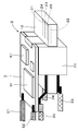
- FIG. 2 is a schematic diagram showing an outline of the configuration of the connector provided at one end of the cable portion 1.
- FIG. 3 is a schematic diagram showing an outline of the electrical configuration of the cable.
- the connector 2 includes a connector body 11 made of synthetic resin, a sheet metal connector shell 12 attached to the connector body 11, and a substrate 3. Although illustration is omitted, these are covered with resin so that the tip of the connector shell 12 is exposed.
- VBUS terminal 21, GND terminal 22, D + terminal 23, D ⁇ terminal 24, and ID terminal 25, which are connector terminals, are juxtaposed on the protruding portion of connector body 11 covered with connector shell 12.
- the cable unit 1 includes a VBUS line 31 constituting a + power line as a power line, a GND line 32 constituting a ⁇ power line, and a D + line as two data communication lines + and ⁇ for signal transmission. 33, D-line 34, and shield line 35.
- the D + terminal 23 is electrically connected to the D + line 33.
- the D-terminal 24 is electrically connected to the D-line 34.
- the shield wire 35 is electrically connected to the connector shell 12.
- the VBUS line 31 and the GND line 32 are connected to the substrate 3 on which the protection circuit is mounted.
- the VBUS line 31 is electrically connected to the VBUS terminal 21 via the substrate 3
- the GND line 32 is connected to the substrate 3 via the substrate 3. It is electrically connected to the GND terminal 22.
- the protection circuit includes a switch S1 and a temperature detection element 51 such as a thermistor.
- the switch S1 is provided on the + power supply line, and switches between conduction and cutoff of the + power supply line.
- the temperature detecting element 51 connected to the switch S1 detects an abnormal temperature rise
- the switch S1 is turned off and the + power line is cut off.
- the cable can be protected from an abnormal temperature rise due to abnormal heat generation or the like.
- a power supply source USB adapter, AC adapter, power supply, etc.
- FIG. 4 shows a more specific configuration example of the protection circuit corresponding to the protection circuit shown in FIG. Note that the configuration of the protection circuit is not limited to the example shown in FIG.
- the positive power line (VBUS line) is provided with, for example, a MOS (Metal-Oxide-Semiconductor) FET (Field-Effect-Transistor) as a switch S1, and a resistor 52 is connected in parallel to the MOSFET.
- a thermistor is connected as a temperature detecting element 51 to the MOSFET.
- the thermistor is, for example, a PTC (positive temperature coefficient) thermistor whose resistance increases (has a positive temperature coefficient) as the temperature increases.
- the resistance value of the thermistor increases with an abnormal temperature rise, the MOSFET is turned off, and the + power supply line is cut off.
- the cable can be protected from an abnormal temperature rise.
- FIG. 5 is a schematic diagram showing an outline of the configuration of the cable of Modification 1-1.
- the cable of Modification 1-1 includes a cable portion 1, a connector 2, and a substrate 3 on which a protection circuit is mounted.
- the connector 2 is provided at one end of the cable portion 1.
- a connector of a type different from the connector 2 is provided at the other end of the cable portion 1.
- the board 3 is built in the cable portion 1 instead of the connector 2.
- the board 3 is built in the cable portion 1 (preferably in the vicinity of the connector 2) because such heat generation can be detected earlier and protection can be quickly applied. Except for the above, it is the same as the above-described example of the cable.
- Modification 1-2 (First example of other configuration of protection circuit)
- One example of the cable according to the first embodiment and Modification 1-1 may be obtained by changing the configuration of the protection circuit as follows.
- FIG. 6 is a schematic diagram showing a first example of another configuration of the protection circuit.
- a switch S1 for switching between conduction and interruption of the negative power supply line is provided in the negative power supply line.
- the temperature detecting element 51 connected to the switch S1 detects an abnormal temperature rise
- the switch S1 is turned off and the-power line is cut off.
- the cable can be protected from an abnormal temperature rise.
- Modification 1-3 (Second example of other configuration of protection circuit)
- One example of the cable according to the first embodiment and Modification 1-1 may be obtained by changing the configuration of the protection circuit as follows.
- FIG. 7 is a schematic diagram showing a second example of another configuration of the protection circuit.
- a switch S1 is provided in the + power supply line.
- the control unit 61 is connected to the switch S1.
- the control part 61 is comprised by the microcomputer etc., for example. For example, when the control unit 61 monitors the resistance value of the temperature detection element 51 and detects a temperature abnormality, the control unit 61 controls the switch S1 to be in an OFF state and cuts off the + power supply line. As a result, at least the cable can be protected from an abnormal temperature rise.
- the modified example 1-2 may have a configuration in which the control unit 61 is added to the protection circuit.
- the protection operation can be performed with the cable alone.
- a protection operation is typically performed on the AC adapter side (output is stopped due to excessive output current or abnormal temperature rise).
- the protective operation can be performed by the cable alone. Further, it is possible to detect and protect the heat with a single cable without sacrificing the data communication line and without adding a temperature detecting wire.
- the first embodiment of the present technology has an excellent effect as compared with a typical protection operation.
- protection may be applied in the event of abnormal heat generation of the USB connector in an incomplete state such as an abnormality in the connector terminal of the USB cable, foreign matter contamination, contact failure, etc.
- the power supply (AC adapter), the USB cable, and the set device, which are power supply sources, cannot be protected.
- protection can be performed with a single cable, and protection can be performed using a method that does not depend on an AC adapter or a power source.
- current or voltage such as excessive current or voltage
- the temperature of abnormal heat generation is detected, so the heat at the time of abnormality is detected quickly.
- the current can be stopped.
- the connector terminal is in an incomplete state such as an abnormality in the connector, foreign matter, or contact failure.
- the USB cable or the set-side connector is melted or smoked safely due to abnormal heat generation of the USB connector without depending on the AC adapter and the power source, Since it can detect and stop, it is effective as protection for ensuring the safety of the user who uses it. Furthermore, it can be used safely without affecting the AC adapter and power supply.
- Second Embodiment An example of the configuration of a cable according to a second embodiment of the present technology will be described.
- An example of the cable according to the second embodiment of the present technology includes, for example, a cable portion 1 and a connector 2 as in the first embodiment.
- the connector 2 is provided at one end of the cable portion 1.
- a connector of a type different from the connector 2 is provided at the other end of the cable portion 1.
- 8A and 8B are schematic diagrams for explaining the outline of the configuration of the connector 2.
- 8A shows a state before the protection operation is performed
- FIG. 8B shows a state after the protection operation is performed.
- 8A and 8B illustration of the D + line 33 electrically connected to the D + terminal 23 and the D ⁇ line 34 electrically connected to the D ⁇ terminal 24 is omitted.
- the GND line 32 is electrically connected to the GND terminal 22.
- the VBUS line 31 is electrically connected to the VBUS terminal 21 via the protective member 70.
- the protective member 70 includes a case 71 made of an insulating material and the like, and an elastic conductive member 72 made of a material whose shape changes with temperature, such as a shape memory alloy housed in the case 71.
- the protection member 70 is built in the connector 2, for example.
- the protective member 70 may be built in the cable part 1 or may be built over both the connector 2 and the cable part 1.
- the expansion / contraction conductive member 72 is, for example, a spring-shaped shape memory alloy or the like that has a characteristic of being stretched at a normal operation temperature (low temperature, room temperature, etc.) and contracted at a high temperature.
- the protective member 70 is installed in series with the + power supply line, and switches between conduction and blocking of the + power supply line according to a shape change such as expansion and / or contraction of the expandable conductive member 72.
- the + power supply line is cut off due to a shape change such as a change in a state where the expandable conductive member 72 is contracted.
- a shape change such as a change in a state where the expandable conductive member 72 is contracted.
- the contact between each of the VBUS line 31 and the VBUS terminal 21 and one end and the other end of the expandable conductive member 72 is released. Is cut off.
- at least the cable can be protected from an abnormal temperature rise.
- the protection operation can be performed with a single cable.
- FIG. 9A and 9B are schematic diagrams for explaining the outline of the configuration of the connector 2.
- FIG. 9A shows a state before the protective operation is performed
- FIG. 9B shows a state after the protective operation is performed.
- 9A and 9B illustration of the D + line 33 electrically connected to the D + terminal 23 and the D ⁇ line 34 electrically connected to the D ⁇ terminal 24 is omitted.
- the VBUS line 31 is electrically connected to the VBUS terminal 21.
- the GND line 32 is electrically connected to the GND terminal 22 through the protective member 70.
- the protective member 70 is installed in series with the ⁇ power supply line, and switches between conduction and interruption of the ⁇ power supply line according to a shape change such as expansion and / or contraction of the expandable conductive member 72.
- the stretchable conductive member 72 in a state of a normal operation temperature (low temperature, normal temperature, etc.), the stretchable conductive member 72 is stretched, and both ends of the stretchable conductive member 72 are connected to the GND line 32 and GND, respectively. It is in a state of being electrically connected to each of the terminals 22.
- a normal operation temperature low temperature, normal temperature, etc.
- the ⁇ power line is cut off due to a shape change such as a change in a state where the stretchable conductive member 72 is shrunk.
- a shape change such as a change in a state where the stretchable conductive member 72 is shrunk.
- at least the cable can be protected from an abnormal temperature rise.
- the second embodiment of the present technology described above has the same effect as the first embodiment.
- the protection operation can be performed with a single cable without using a temperature detection element such as a thermistor.
- FIG. 10 is a schematic diagram showing an outline of the configuration of the above-described power supply apparatus.
- the power supply device includes an AC adapter 80 and a cable 90 connected to the AC adapter 80.
- the cable 90 includes a cable portion 91 and a connector 92 provided at one end of the cable portion 91.
- the other end of the cable portion 91 is provided with a connector of a type different from the connector 92 connected to the AC adapter 80.
- the cable unit 91 may be connected to the AC adapter 80 without using a connector.
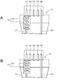
- FIG. 11A and FIG. 11B are schematic diagrams for explaining an outline of the configuration of the connector 92.
- 11A shows a state before the protection operation is performed
- FIG. 11B shows a state after the protection operation is performed.
- illustration of the D + line 33 electrically connected to the D + terminal 23 and the D ⁇ line 34 electrically connected to the D ⁇ terminal 24 is omitted.
- the expansion / contraction conductive member 72 is, for example, a spring-shaped shape memory alloy that has a characteristic of being contracted at a normal operation temperature (low temperature, normal temperature, etc.) and being expanded at a high temperature.
- a normal operation temperature low temperature, normal temperature, etc.
- the stretchable conductive member 72 included in the case 71 of the protective member 70 is in a contracted state, and the + power line and the ⁇ power line Are not short-circuited by the stretchable conductive member 72.
- the temperature rises due to an abnormal temperature rise or the like as shown in FIG.
- the stretchable conductive member 72 is stretched, and both ends of the stretchable conductive member 72 are connected to the + power supply line and Each of the ⁇ power supply lines is electrically connected, and the + power supply line and the ⁇ power supply line are short-circuited by the expandable conductive member 72.
- the overcurrent protection operation by the protection circuit of the AC adapter 80 operates, and the output of the AC adapter 80 can be stopped.
- the cable can be protected from an abnormal temperature rise.
- the cable, the AC adapter 80 connected to the cable, and the device that is the power supply destination connected to the cable can be protected. If the temperature does not drop to the temperature at which it deforms after the high temperature state, the stretchable conductive member remains stretched, and the + power supply line and the ⁇ power supply line are short-circuited by the stretchable conductive member 72. Maintained.
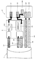
- FIG. 12 is a schematic diagram showing an outline of the electrical configuration of the AC adapter.
- the alternating current supplied from the external power source to the AC adapter 80 is converted into direct current by the AC-DC circuit 81, and power is supplied through the connector 102 through the power line.
- the VBUS line 31 constituting the + power line of the cable 100 is connected to the switch S82.
- the on / off state of the switch S82 is controlled by the load switch SW control circuit 83.
- the cable unit 101 includes a VBUS line 31 that constitutes a + power supply line as a power supply line, a GND line 32 that constitutes a ⁇ power supply line, and a D + line as two data communication lines + and ⁇ for signal transmission. 33, D-line 34, shield line 35, and connection detection line 36 for connection detection.
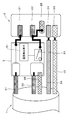
- FIG. 13 is a side view showing an outline of the configuration of the connector viewed from the side.
- a claw 111 that is a protruding portion that moves upward
- a connection portion 112 that moves upward in conjunction with the rise of the claw 111
- a connection detection line 36 of the cable portion 101 On the lower surface of the metal portion at the tip of the connector 102, there are a claw 111 that is a protruding portion that moves upward, a connection portion 112 that moves upward in conjunction with the rise of the claw 111, and a connection detection line 36 of the cable portion 101. And a connected connection detection terminal portion 113.
- the claw 111 rises, and the bottom of the connection portion 112 is pushed up by the claw 111, so that the connection portion 112 rises.
- the upper end part of the connection part 112 and the connection detection terminal part 113 are short-circuited.
- the shield (metal portion at the tip) that is electrically connected to the connection portion 112 is connected to GND, and the connector connection is detected when the potential of the connection detection line drops to the GND level.
- the power supply of the + power supply line (VBUS line) is stopped.
- the power supply is turned on and off by controlling the switch S82 provided in the + power supply line using the detection signal. Thereby, it is possible to prevent an abnormal state from occurring when the connector 102 is not connected to an electronic device or the like.
- the cable may be of the same type as the connector at one end and the other end of the cable portion 1.
- the protective member 70 may be installed on both the positive power line and the negative power line.
- a fuse may be used instead of the protective member 70 in the second embodiment.
- a configuration in which a thermistor is installed in the vicinity of a connector on a device side connected to a USB cable can be employed.
- a thermistor is installed in the vicinity of the battery, and a circuit that stops charging when the battery becomes hot is employed.
- charging is stopped, and a stop signal is sent to the adapter side to stop power supply from the adapter.
- the stop signal is sent as follows. (1) When DCP (Dedicated Charging Port) is not used in the normal USB 2.0 / USB 3.0 standard, D + / D- is not used, so that signal line is used.
- DCP Dedicated Charging Port
- the cable can be protected from abnormal heat generation when the device is connected. For example, it is possible to protect a cable, an adapter that is a power supply source connected to the cable, and a device that is a power supply destination connected to the cable from abnormal heat generation. Since the temperature detection element is provided on the device side, there is an advantage that processing of the cable portion and the connector is not necessary.
- a cable part including a power line constituting the power line; and A connector provided on at least one of one end and the other end of the cable portion;
- a cable comprising: a temperature detection element; and a circuit board having a protection circuit including a switch that receives a detection result of the temperature detection element and switches between conduction and interruption of the power supply line.
- the circuit board is built in at least one of the connector and the cable portion.
- the cable according to [6] wherein the conductive member is provided in a + power supply line or a ⁇ power supply line.
- a power supply, A power supply apparatus comprising: the cable according to any one of [1] to [5] connected to the power supply source.
- a power supply, A power supply apparatus comprising: the cable according to any one of [6] to [10] connected to the power supply source.
- a power supply, A power supply device comprising: the cable according to [11] connected to the power supply source.
Abstract
Description
まず本技術の理解を容易にするため、本技術の技術的背景について説明する。USB(Universal Serial Bus)を用いた給電規格は、BC1.2(Battery Charging Specification Revision1.2)のリリースにより1.5Aまで拡大され、またUSB-PD(Power Delivery)や各メーカーの独自規格等の登場でさらなる大電流化が進んでいる。一方で、USBケーブルのコネクタは、マイクロUSB等の小型なものが一般的となり、端子の変形によるショートやケーブル内部の変形劣化によるショート、端子に異物が混入しショート等が起こりやすい。大電流化によって、充電器の過電流保護の値が大きくなっているため、市場において異常発熱によるケーブルの焼損等が増加している。ショートによる発熱は局地的に発生するため、異常温度を迅速に検出して、ケーブル、並びに、ケーブルに接続された電力供給源およびケーブルに接続された電力供給先である機器を保護することが求められている。
1.第1の実施の形態
2.第2の実施の形態
3.第3の実施の形態
4.第4の実施の形態
5.他の実施の形態(変形例)
なお、以下に説明する実施の形態等は本技術の好適な具体例であり、本技術の内容がこれらの実施の形態等に限定されるものではない。また、本明細書に記載された効果はあくまで例示であって限定されるものではなく、また例示した効果と異なる効果が存在することを否定するものではない。
本技術の第1の実施の形態によるケーブルの構成の一例について説明する。図1は、本技術の第1の実施の形態によるケーブルの構成の一例の概略を示す概略図である。図1に示すように、本技術の第1の実施の形態によるケーブルは、ケーブル部1と、コネクタ2と、保護回路を搭載した基板3とを備える。例えば、本技術の第1の実施の形態によるケーブルは、マイクロUSBケーブル等のUSBケーブルである。本技術の第1の実施の形態によるケーブルは、例えば、USBアダプタ、ACアダプタ、電源等の電力供給源に接続されて出力ケーブルとして使用することができる。なお、電源としては、例えば、USB出力機能付きポータブル電源等のリチウムイオンポリマー電池等の電池を内蔵した電源等が挙げられる。
(基板の配置を変更した例)
第1の実施の形態によるケーブルの一例は、基板3の配置を次のように変更したものであってもよい。
(保護回路の他の構成の第1の例)
第1の実施の形態によるケーブルの一例および変形例1-1は、保護回路の構成を次のように変更したものであってもよい。
(保護回路の他の構成の第2の例)
第1の実施の形態によるケーブルの一例および変形例1-1は、保護回路の構成を次のように変更したものであってもよい。
本技術の第2の実施の形態によるケーブルの構成の一例について説明する。
第2の実施の形態によるケーブルの一例は、保護部材70の配置を次のように変更したものであってもよい。
本技術の第3の実施の形態によるケーブルについて説明する。以下では、第3の実施の形態によるケーブルを電力供給装置に適用した例について説明する。例えば、ケーブルの他端がACアダプタに接続された電力供給装置の構成例について説明する。
本技術の第4の実施の形態によるケーブルについて説明する。以下では、第4の実施の形態によるケーブルを電力供給装置に適用した例について説明する。例えば、ケーブルの他端がACアダプタに接続された電力供給装置の構成例について説明する。電力供給装置は、ACアダプタ80とACアダプタ80に接続されたケーブル100とを備える。ケーブル90は、ケーブル部91と、ケーブル部91の一端に設けられたコネクタ92とを備える。ケーブル部91の他端はACアダプタ80に接続されたコネクタ92とは異なるタイプのコネクタが設けられている。なお、コネクタを介さないでACアダプタ80に接続されていてもよい。
ケーブル部101は、電源線として、+の電源ラインを構成するVBUS線31と、-の電源ラインを構成するGND線32と、信号伝送用の+、-の2本のデータ通信線としてD+線33、D-線34と、シールド線35と、接続検出のための接続検出線36とを含む。
図13は、コネクタを側方から見た構成の概略を示す側面図である。コネクタ102の先端の金属部分の下面には、上方に可動する突出部である爪111と、爪111の上昇と連動して上方に可動する接続部112と、ケーブル部101の接続検出線36と接続された接続検出端子部113とを備える。例えば、コネクタ102が、コネクタ挿し込み口に挿し込まれると爪111が上昇し、接続部112の底面が爪111により押し上げられることにより、接続部112が上昇する。これにより、接続部112の上端部と接続検出端子部113とをショートさせる。接続部112と電気的に接続されているシールド(先端の金属部分)は、GNDに接続されており、接続検出ラインの電位がGNDレベルまで落ちることでコネクタ接続の検出を行う。コネクタ102がデバイスと未接続と検出された場合、+の電源ライン(VBUSライン)の電力供給を停止する。例えば、検出信号を用いて、+の電源ラインに設けられたスイッチS82の制御を行うことで、電力供給のオンおよびオフの動作を行う。これにより、コネクタ102が電子機器等と接続されていない状態において、異常状態が発生することを防止することができる。
本技術は、上述した本技術の実施の形態に限定されるものでは無く、本技術の要旨を逸脱しない範囲内で様々な変形や応用が可能である。
[1]
電源ラインを構成する電源線を含むケーブル部と、
該ケーブル部の一端および他端の少なくとも何れかに設けられたコネクタと、
温度検出素子、並びに、該温度検出素子の検出結果を受け、前記電源ラインの導通および遮断を切り替える動作を行うスイッチを含む保護回路を有する回路基板と
を備えたケーブル。
[2]
前記回路基板は、前記コネクタおよび前記ケーブル部の少なくとも何れかに内蔵された[1]に記載のケーブル。
[3]
前記スイッチは、+の電源ラインまたは-の電源ラインに設けられた[1]~[2]の何れかに記載のケーブル。
[4]
前記保護回路は、前記温度検出素子の検出結果を受け、前記スイッチの動作を制御する制御部をさらに含む[1]~[3]の何れかに記載のケーブル。
[5]
USB規格に準拠したケーブルである[1]~[4]の何れかに記載のケーブル。
[6]
電源ラインを構成する電源線を含むケーブル部と、
該ケーブル部の一端および他端の少なくとも何れかに設けられたコネクタと、
前記電源ラインに設けられ、温度変化に伴う形状変化により、前記電源ラインの導通および遮断を切り替える導電部材と
を備えたケーブル。
[7]
前記導電部材は、+の電源ラインまたは-の電源ラインに設けられた[6]に記載のケーブル。
[8]
前記導電部材は、形状記憶合金である[6]~[7]の何れかに記載のケーブル。
[9]
前記形状記憶合金は、バネ状である[8]に記載のケーブル。
[10]
前記導電部材は、前記コネクタに内蔵されている[6]~[9]の何れかに記載のケーブル。
[11]
電源ラインを構成する電源線を含むケーブル部と、
該ケーブル部の一端および他端の少なくとも何れかに設けられたコネクタと、
温度変化に伴う形状変化により、+の電源ラインと-の電源ラインとをショートさせる導電部材と
を備えたケーブル。
[12]
電力供給源と、
該電力供給源に接続された[1]~[5]の何れかに記載のケーブルと
を備えた電力供給装置。
[13]
電力供給源と、
該電力供給源に接続された[6]~[10]の何れかに記載のケーブルと
を備えた電力供給装置。
[14]
電力供給源と、
該電力供給源に接続された[11]に記載のケーブルと
を備えた電力供給装置。
Claims (14)
- 電源ラインを構成する電源線を含むケーブル部と、
該ケーブル部の一端および他端の少なくとも何れかに設けられたコネクタと、
温度検出素子、並びに、該温度検出素子の検出結果を受け、前記電源ラインの導通および遮断を切り替える動作を行うスイッチを含む保護回路を有する回路基板と
を備えたケーブル。 - 前記回路基板は、前記コネクタおよび前記ケーブル部の少なくとも何れかに内蔵された請求項1に記載のケーブル。
- 前記スイッチは、+の電源ラインまたは-の電源ラインに設けられた請求項1に記載のケーブル。
- 前記保護回路は、前記温度検出素子の検出結果を受け、前記スイッチの動作を制御する制御部をさらに含む請求項1に記載のケーブル。
- USB規格に準拠したケーブルである請求項1に記載のケーブル。
- 電源ラインを構成する電源線を含むケーブル部と、
該ケーブル部の一端および他端の少なくとも何れかに設けられたコネクタと、
前記電源ラインに設けられ、温度変化に伴う形状変化により、前記電源ラインの導通および遮断を切り替える導電部材と
を備えたケーブル。 - 前記導電部材は、+の電源ラインまたは-の電源ラインに設けられた請求項6に記載のケーブル。
- 前記導電部材は、形状記憶合金である請求項6に記載のケーブル。
- 前記形状記憶合金は、バネ状である請求項8に記載のケーブル。
- 前記導電部材は、前記コネクタに内蔵されている請求項6に記載のケーブル。
- 電源ラインを構成する電源線を含むケーブル部と、
該ケーブル部の一端および他端の少なくとも何れかに設けられたコネクタと、
温度変化に伴う形状変化により、+の電源ラインと-の電源ラインとをショートさせる導電部材と
を備えたケーブル。 - 電力供給源と、
該電力供給源に接続された請求項1に記載のケーブルと
を備えた電力供給装置。 - 電力供給源と、
該電力供給源に接続された請求項6に記載のケーブルと
を備えた電力供給装置。 - 電力供給源と、
該電力供給源に接続された請求項11に記載のケーブルと
を備えた電力供給装置。
Priority Applications (3)
| Application Number | Priority Date | Filing Date | Title |
|---|---|---|---|
| US15/314,968 US10574004B2 (en) | 2014-06-13 | 2015-03-23 | Cable and power supply device |
| CN201580029940.6A CN106415945B (zh) | 2014-06-13 | 2015-03-23 | 电缆和电源供应设备 |
| JP2016527613A JP6690533B2 (ja) | 2014-06-13 | 2015-03-23 | ケーブルおよび電力供給装置 |
Applications Claiming Priority (2)
| Application Number | Priority Date | Filing Date | Title |
|---|---|---|---|
| JP2014122570 | 2014-06-13 | ||
| JP2014-122570 | 2014-06-13 |
Publications (1)
| Publication Number | Publication Date |
|---|---|
| WO2015190020A1 true WO2015190020A1 (ja) | 2015-12-17 |
Family
ID=54833139
Family Applications (1)
| Application Number | Title | Priority Date | Filing Date |
|---|---|---|---|
| PCT/JP2015/001599 WO2015190020A1 (ja) | 2014-06-13 | 2015-03-23 | ケーブルおよび電力供給装置 |
Country Status (4)
| Country | Link |
|---|---|
| US (1) | US10574004B2 (ja) |
| JP (1) | JP6690533B2 (ja) |
| CN (1) | CN106415945B (ja) |
| WO (1) | WO2015190020A1 (ja) |
Cited By (7)
| Publication number | Priority date | Publication date | Assignee | Title |
|---|---|---|---|---|
| JP2015201420A (ja) * | 2014-04-03 | 2015-11-12 | ホシデン株式会社 | コネクタ |
| JP2016100059A (ja) * | 2014-11-18 | 2016-05-30 | 株式会社トップランド | Usbプラグ |
| EP3232519A1 (en) * | 2016-04-15 | 2017-10-18 | Steven Yue | Power interface device |
| CN107302242A (zh) * | 2016-04-15 | 2017-10-27 | 喻孟华 | 取电装置 |
| CN107359490A (zh) * | 2016-05-09 | 2017-11-17 | 喻孟华 | 取电装置 |
| KR20190037266A (ko) * | 2016-08-02 | 2019-04-05 | 보우린스, 인크. | 통합된 리셋 가능한 온도 퓨즈를 구비한 커넥터 |
| JP2021051930A (ja) * | 2019-09-25 | 2021-04-01 | ボーンズ株式会社 | コネクタ及びコネクタケーブル |
Families Citing this family (7)
| Publication number | Priority date | Publication date | Assignee | Title |
|---|---|---|---|---|
| JP6187408B2 (ja) * | 2014-07-30 | 2017-08-30 | アイシン・エィ・ダブリュ株式会社 | 電力変換装置の制御基板 |
| JP6295887B2 (ja) * | 2014-08-22 | 2018-03-20 | ミツミ電機株式会社 | プラグ付きケーブル及び制御回路及び基板 |
| JP6711582B2 (ja) * | 2015-10-14 | 2020-06-17 | ホシデン株式会社 | プラグコネクタ及びアダプタ |
| JP2017187933A (ja) * | 2016-04-06 | 2017-10-12 | ルネサスエレクトロニクス株式会社 | 半導体装置、半導体装置の制御方法および給電システム |
| CN109449692B (zh) * | 2017-09-01 | 2020-06-12 | 硕天科技股份有限公司 | 配接器与配接器模块 |
| TWI735861B (zh) * | 2019-04-09 | 2021-08-11 | 佳必琪國際股份有限公司 | 具有元件保護構件之高頻連接器及其製造方法 |
| DE102021132442A1 (de) | 2021-12-09 | 2023-06-15 | Bayerische Motoren Werke Aktiengesellschaft | Elektrisches Verbindungselement und Fahrzeug damit |
Citations (11)
| Publication number | Priority date | Publication date | Assignee | Title |
|---|---|---|---|---|
| JPS6293874A (ja) * | 1985-10-21 | 1987-04-30 | 株式会社東芝 | 電気接続構造 |
| JPH05159828A (ja) * | 1991-12-04 | 1993-06-25 | Nec Eng Ltd | 電源プラグ |
| JPH0767245A (ja) * | 1993-08-27 | 1995-03-10 | Janome Sewing Mach Co Ltd | 電源供給回路の安全装置 |
| JPH09223547A (ja) * | 1996-02-16 | 1997-08-26 | Hisayoshi Miyamoto | 火災防止機構のコンセント |
| JPH1032056A (ja) * | 1996-07-17 | 1998-02-03 | Sharp Corp | 感熱式安全コンセント |
| JPH10326646A (ja) * | 1996-11-20 | 1998-12-08 | Sumitomo Electric Ind Ltd | 遮断機能付き電源プラグ |
| WO2004030027A2 (en) * | 2002-09-25 | 2004-04-08 | Emerson Electric Co. | An electrical connector having a separable connection and method therefor |
| WO2009019801A1 (ja) * | 2007-08-08 | 2009-02-12 | Fuji Electric Wire Industries Co., Ltd. | 電源コード |
| WO2013069107A1 (ja) * | 2011-11-09 | 2013-05-16 | 富士電線工業株式会社 | プラグの電線配線構造 |
| JP2014056678A (ja) * | 2012-09-11 | 2014-03-27 | Panasonic Corp | 電源コード |
| JP2014075333A (ja) * | 2012-09-11 | 2014-04-24 | Panasonic Corp | 電源コード |
Family Cites Families (14)
| Publication number | Priority date | Publication date | Assignee | Title |
|---|---|---|---|---|
| JPH10320056A (ja) | 1997-05-20 | 1998-12-04 | Kikuko Yamamoto | 液体定量吸引排出装置 |
| JP2002190412A (ja) * | 2000-12-20 | 2002-07-05 | Hitachi Metals Ltd | ノイズ抑制機能を有すインターフェースケーブル |
| JP2003092516A (ja) | 2001-09-18 | 2003-03-28 | Hitachi Kokusai Electric Inc | 増幅装置 |
| JP3099411U (ja) * | 2003-07-23 | 2004-04-08 | 水口 覚志 | Usbプラグ及びusbケーブル |
| CN2665721Y (zh) * | 2003-09-27 | 2004-12-22 | 东莞林发电子有限公司 | 通用串行总线速度指示器 |
| CN201204338Y (zh) * | 2008-05-05 | 2009-03-04 | 车晋绥 | 安全插头 |
| US8339760B2 (en) * | 2009-06-15 | 2012-12-25 | Apple Inc. | Thermal protection circuits and structures for electronic devices and cables |
| US8498087B2 (en) * | 2009-11-03 | 2013-07-30 | Apple Inc. | Thermal protection circuits for electronic device cables |
| CN201601333U (zh) * | 2010-01-29 | 2010-10-06 | 深大宇电器(深圳)有限公司 | 一种插座 |
| KR200458625Y1 (ko) * | 2011-02-28 | 2012-06-07 | 안광주 | 데이터 케이블 |
| JP5867587B2 (ja) * | 2012-03-08 | 2016-02-24 | パナソニックIpマネジメント株式会社 | 充電ケーブル |
| CN104756340A (zh) * | 2013-10-24 | 2015-07-01 | 三洋电机株式会社 | 电气线缆以及电源装置 |
| JP6280482B2 (ja) * | 2014-04-03 | 2018-02-14 | ホシデン株式会社 | コネクタ |
| JP6711582B2 (ja) * | 2015-10-14 | 2020-06-17 | ホシデン株式会社 | プラグコネクタ及びアダプタ |
-
2015
- 2015-03-23 WO PCT/JP2015/001599 patent/WO2015190020A1/ja active Application Filing
- 2015-03-23 CN CN201580029940.6A patent/CN106415945B/zh active Active
- 2015-03-23 JP JP2016527613A patent/JP6690533B2/ja active Active
- 2015-03-23 US US15/314,968 patent/US10574004B2/en not_active Expired - Fee Related
Patent Citations (11)
| Publication number | Priority date | Publication date | Assignee | Title |
|---|---|---|---|---|
| JPS6293874A (ja) * | 1985-10-21 | 1987-04-30 | 株式会社東芝 | 電気接続構造 |
| JPH05159828A (ja) * | 1991-12-04 | 1993-06-25 | Nec Eng Ltd | 電源プラグ |
| JPH0767245A (ja) * | 1993-08-27 | 1995-03-10 | Janome Sewing Mach Co Ltd | 電源供給回路の安全装置 |
| JPH09223547A (ja) * | 1996-02-16 | 1997-08-26 | Hisayoshi Miyamoto | 火災防止機構のコンセント |
| JPH1032056A (ja) * | 1996-07-17 | 1998-02-03 | Sharp Corp | 感熱式安全コンセント |
| JPH10326646A (ja) * | 1996-11-20 | 1998-12-08 | Sumitomo Electric Ind Ltd | 遮断機能付き電源プラグ |
| WO2004030027A2 (en) * | 2002-09-25 | 2004-04-08 | Emerson Electric Co. | An electrical connector having a separable connection and method therefor |
| WO2009019801A1 (ja) * | 2007-08-08 | 2009-02-12 | Fuji Electric Wire Industries Co., Ltd. | 電源コード |
| WO2013069107A1 (ja) * | 2011-11-09 | 2013-05-16 | 富士電線工業株式会社 | プラグの電線配線構造 |
| JP2014056678A (ja) * | 2012-09-11 | 2014-03-27 | Panasonic Corp | 電源コード |
| JP2014075333A (ja) * | 2012-09-11 | 2014-04-24 | Panasonic Corp | 電源コード |
Cited By (12)
| Publication number | Priority date | Publication date | Assignee | Title |
|---|---|---|---|---|
| JP2015201420A (ja) * | 2014-04-03 | 2015-11-12 | ホシデン株式会社 | コネクタ |
| JP2016100059A (ja) * | 2014-11-18 | 2016-05-30 | 株式会社トップランド | Usbプラグ |
| EP3232519A1 (en) * | 2016-04-15 | 2017-10-18 | Steven Yue | Power interface device |
| JP2017191606A (ja) * | 2016-04-15 | 2017-10-19 | 孟華 喩 | アクセス装置 |
| CN107302242A (zh) * | 2016-04-15 | 2017-10-27 | 喻孟华 | 取电装置 |
| CN107359490A (zh) * | 2016-05-09 | 2017-11-17 | 喻孟华 | 取电装置 |
| KR20190037266A (ko) * | 2016-08-02 | 2019-04-05 | 보우린스, 인크. | 통합된 리셋 가능한 온도 퓨즈를 구비한 커넥터 |
| JP2019525416A (ja) * | 2016-08-02 | 2019-09-05 | ボーンズ、インコーポレイテッド | 統合リセット可能温度ヒューズ付きのコネクタ |
| US11456565B2 (en) | 2016-08-02 | 2022-09-27 | Bourns, Inc. | Connector with integrated resettable thermal fuse |
| KR102449996B1 (ko) * | 2016-08-02 | 2022-09-30 | 보우린스, 인크. | 통합된 리셋 가능한 온도 퓨즈를 구비한 커넥터 |
| JP7291621B2 (ja) | 2016-08-02 | 2023-06-15 | ボーンズ、インコーポレイテッド | 統合リセット可能温度ヒューズ付きのコネクタ |
| JP2021051930A (ja) * | 2019-09-25 | 2021-04-01 | ボーンズ株式会社 | コネクタ及びコネクタケーブル |
Also Published As
| Publication number | Publication date |
|---|---|
| US20170201050A1 (en) | 2017-07-13 |
| JPWO2015190020A1 (ja) | 2017-04-20 |
| CN106415945A (zh) | 2017-02-15 |
| US10574004B2 (en) | 2020-02-25 |
| JP6690533B2 (ja) | 2020-04-28 |
| CN106415945B (zh) | 2020-10-16 |
Similar Documents
| Publication | Publication Date | Title |
|---|---|---|
| WO2015190020A1 (ja) | ケーブルおよび電力供給装置 | |
| US10439338B2 (en) | Cable with plug, control circuit and substrate | |
| EP2677616B1 (en) | Interface unit comprising an overcurrent and overvoltage protection device | |
| US9099875B2 (en) | Reverse-connection protecting device and backup power supply including the same | |
| TWI674723B (zh) | 二次電池保護電路及二次電池保護電路的運作方法 | |
| US10498092B2 (en) | Connector with over-temperature and over-current protection | |
| US9570929B2 (en) | Field device with a battery unit | |
| WO2013108336A1 (ja) | 二次電池保護回路、電池パック及び電子機器 | |
| KR101729730B1 (ko) | 과전류로부터 배터리를 보호하는 장치 | |
| US10554058B2 (en) | Systems and methods for monitoring an operating status of a connector | |
| KR20170031062A (ko) | 과충전 및/또는 심방전 방지 방식 배터리 시스템 | |
| US7800249B1 (en) | Power supply system | |
| JP6804892B2 (ja) | 電気機器 | |
| CN104716704B (zh) | 电池状态监视电路以及电池装置 | |
| CN203932973U (zh) | 漏电保护装置 | |
| US20150349514A1 (en) | Multifunctional electrical power output protection device | |
| CN103107520A (zh) | 锂离子电池过温保护系统及方法 | |
| JP6233756B2 (ja) | 温度検出を備えたユニバーサルシリアルバス | |
| EP4192706A1 (en) | Method and system for temperature regulation for a portable charger | |
| CN102570389B (zh) | 一种万用电表高压误测保护方法及万用电表 | |
| JP2010220277A (ja) | 異常電圧保護回路 | |
| JP3207782U (ja) | 電流及び温度保護機能を具えるコネクタプラグの構造 | |
| JP4536040B2 (ja) | 電気機器 | |
| CN110086219B (zh) | 一种充电底座 | |
| KR20150110248A (ko) | 이동통신 모뎀 시스템 |
Legal Events
| Date | Code | Title | Description |
|---|---|---|---|
| 121 | Ep: the epo has been informed by wipo that ep was designated in this application |
Ref document number: 15807585 Country of ref document: EP Kind code of ref document: A1 |
|
| ENP | Entry into the national phase |
Ref document number: 2016527613 Country of ref document: JP Kind code of ref document: A |
|
| WWE | Wipo information: entry into national phase |
Ref document number: 15314968 Country of ref document: US |
|
| NENP | Non-entry into the national phase |
Ref country code: DE |
|
| 122 | Ep: pct application non-entry in european phase |
Ref document number: 15807585 Country of ref document: EP Kind code of ref document: A1 |