WO2015182673A1 - Débitmètre à ultrasons - Google Patents
Débitmètre à ultrasons Download PDFInfo
- Publication number
- WO2015182673A1 WO2015182673A1 PCT/JP2015/065291 JP2015065291W WO2015182673A1 WO 2015182673 A1 WO2015182673 A1 WO 2015182673A1 JP 2015065291 W JP2015065291 W JP 2015065291W WO 2015182673 A1 WO2015182673 A1 WO 2015182673A1
- Authority
- WO
- WIPO (PCT)
- Prior art keywords
- ultrasonic
- tubular body
- ultrasonic flowmeter
- flowmeter according
- present
- Prior art date
Links
Images


Classifications
-
- G—PHYSICS
- G01—MEASURING; TESTING
- G01F—MEASURING VOLUME, VOLUME FLOW, MASS FLOW OR LIQUID LEVEL; METERING BY VOLUME
- G01F1/00—Measuring the volume flow or mass flow of fluid or fluent solid material wherein the fluid passes through a meter in a continuous flow
- G01F1/66—Measuring the volume flow or mass flow of fluid or fluent solid material wherein the fluid passes through a meter in a continuous flow by measuring frequency, phase shift or propagation time of electromagnetic or other waves, e.g. using ultrasonic flowmeters
- G01F1/662—Constructional details
-
- G—PHYSICS
- G01—MEASURING; TESTING
- G01F—MEASURING VOLUME, VOLUME FLOW, MASS FLOW OR LIQUID LEVEL; METERING BY VOLUME
- G01F1/00—Measuring the volume flow or mass flow of fluid or fluent solid material wherein the fluid passes through a meter in a continuous flow
- G01F1/66—Measuring the volume flow or mass flow of fluid or fluent solid material wherein the fluid passes through a meter in a continuous flow by measuring frequency, phase shift or propagation time of electromagnetic or other waves, e.g. using ultrasonic flowmeters
- G01F1/667—Arrangements of transducers for ultrasonic flowmeters; Circuits for operating ultrasonic flowmeters
- G01F1/668—Compensating or correcting for variations in velocity of sound
Definitions
- the present invention relates to an ultrasonic flowmeter including an ultrasonic transducer.
- FIG. 1 is a schematic view of an ultrasonic flowmeter in which a predetermined interval is provided in a tubular body 2 using ultrasonic transducers 1a and 1b formed in a ring shape on a conventional transceiver.
- the ultrasonic flowmeter uses a total of two ultrasonic transducers in a ring shape, one each for transmission and reception. In this structure, the ultrasonic signal level was weak and measurement was difficult.
- an ultrasonic vibrator is directly attached to a pipe body through which a fluid flows, there is reverberation due to a long ultrasonic signal, which affects the next transmission / reception ultrasonic signal and cannot perform stable measurement.
- the ultrasonic flowmeter described above must produce a transmission / reception ultrasonic transducer in accordance with the tube diameter. In addition, it is necessary to cut the tube when attaching the ultrasonic transducer.
- Ultrasonic flowmeters are generally equipped with a structure that is installed between pipes, and when installing an ultrasonic flowmeter in an existing pipe later, the pipe is disconnected to install the ultrasonic flowmeter. Therefore, it is difficult to install an ultrasonic flowmeter later on existing piping.
- An object of the present invention is to provide an ultrasonic flowmeter that can increase the amplitude of an excitation signal and improve the reception sensitivity in consideration of the above-described problems.
- the ultrasonic flowmeter according to the present invention includes two or more ultrasonic transducers arranged on the transmission side and the reception side at a distance from each other outside the tubular body through which the fluid flows, and arranged on the transmission side.
- the ultrasonic transducer described above is driven to press the tube body with substantially the same pressure to increase the amplitude of the ultrasonic wave.
- the ultrasonic flowmeter according to the present invention is characterized in that the guide wave is excited by driving the ultrasonic transducer at a frequency having a wavelength equal to or larger than the diameter of the tubular body.
- An ultrasonic flowmeter includes an alignment member that converts an ultrasonic signal suitable for measurement between a tubular body and an ultrasonic transducer, and the alignment member has a curved surface or a groove on a contact surface with the tubular body. It is characterized by providing.
- the ultrasonic flowmeter according to the present invention is characterized in that an ultrasonic transducer disposed in an axially symmetrical manner in a tubular body is driven in the same phase.
- the ultrasonic flowmeter according to the present invention is characterized in that the ultrasonic transducer is one selected from a cylindrical shape, a prismatic shape, a columnar shape, a plate shape, and a flat plate shape.
- the ultrasonic flowmeter according to the present invention is characterized by including a container having a curved or tapered outer surface shape.
- the ultrasonic flowmeter according to the present invention is characterized in that the storage body holds the ultrasonic transducer at a predetermined distance and is detachably attached to the tube body.
- the ultrasonic flowmeter according to the present invention is characterized in that the storage body includes an opening for observing the fluid flowing through the tubular body.
- vibrator and the improvement of a receiving sensitivity can be aimed at, and the ultrasonic signal suitable for a measurement can be obtained.
- a generally used ultrasonic flowmeter is a device that detects an ultrasonic bulk wave (longitudinal wave or transverse wave) transmitted from an ultrasonic transmitter with an ultrasonic receiver.
- the ultrasonic flowmeter according to the present invention excites a guide wave by an ultrasonic transmitter, receives the guide wave propagated through the fluid inside the tubular body by the ultrasonic receiver, and determines the flow velocity of the fluid inside the tubular body. It differs from the commonly used ultrasonic flowmeter in measuring.
- the “guide wave” is a general term for an ultrasonic wave propagation form when propagating in a longitudinal direction in a medium surrounded by a boundary surface having an interval shorter than the ultrasonic wavelength, such as a tubular body, a plate, a rod, and a railroad rail. Means.
- the guide wave is different from the bulk wave in that the longitudinal wave and the transverse wave that have undergone mode conversion at the boundary of the medium are not separated and can be excited by driving the ultrasonic transducer at a frequency that is a wavelength that is equal to or greater than the diameter of the tube. .
- the guide wave is observed when the inside of the tube body is not hollow, that is, when the tube body is filled with fluid.
- the present inventors disclosed an ultrasonic flowmeter using a guide wave.
- the ultrasonic flowmeter of Patent Document 2 is provided with two ultrasonic transducers on the outer peripheral surface of a pipe body through which a fluid flows, with a distance L, and one of the two ultrasonic transducers is on the transmission side and the other is received.
- Propagation time during which the guide wave excited by the drive of the ultrasonic transducer using the tube body and the internal fluid as one medium is propagated from the upstream to the downstream between the ultrasonic transceivers separated by the distance L;
- the flow velocity of the fluid is obtained from the propagation time difference from the propagation time propagating from the downstream to the upstream.
- two ultrasonic vibrators are provided on the outer surface of a pipe body through which a fluid flows and are separated by a distance L, and one of the two ultrasonic vibrators is connected to a transmitter.
- a control / analysis device for obtaining a flow velocity of a fluid from a propagation time difference between a propagation time T 1 when propagating between the ultrasonic transducers separated by L from upstream to downstream and a propagation time T 2 when propagating from downstream to upstream
- an ultrasonic transducer can be attached to a part of the outer surface of the tubular body in the circumferential direction.
- ⁇ is a factor that represents the effect of the flow velocity of the fluid inside the tube on the phase velocity of the guide wave
- ⁇ is a factor that represents the effect of the flow velocity of the fluid inside the tube on the group velocity of the guide wave.
- T 1 L / (vg (0) + ⁇ v)
- T 2 L / (vg (0) ⁇ v).
- the propagation time difference of the guide wave is obtained from the following equation.
- ⁇ 2L ⁇ v / (vg 2 (0)) v / ⁇
- L installation distance of two ultrasonic transducers
- v fluid flow velocity
- vg guide wave group velocity
- ⁇ factor representing the influence of the fluid velocity inside the tube on the guide wave group velocity
- ⁇ vg 2 (0) / 2L ⁇ .
- the present inventors examined an increase in the amplitude of an excitation signal and an improvement in reception sensitivity in order to realize a more accurate flow rate measurement with respect to the ultrasonic flow meter of Patent Document 2.
- the present inventors can increase the amplitude of the excitation signal and improve the reception sensitivity, and further increase the amplitude of the excitation signal much more than twice and the reception sensitivity.
- the present invention was completed by finding out that improvement of the above can be realized.
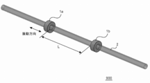
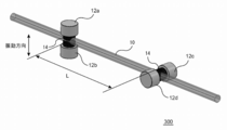
- FIG. 2 is a schematic view showing an ultrasonic flowmeter 100 according to an embodiment of the present invention.
- the ultrasonic flowmeter 100 includes two or more ultrasonic vibrations arranged at a distance L on the transmission side and the reception side outside the tubular body 10 having a path for flowing a fluid to be measured in a direction extending in the longitudinal direction. It has children 12a to 12d.
- FIG. 2 shows an ultrasonic flowmeter in which two ultrasonic transducers are provided on each of the transmission side and the reception side.
- two ultrasonic transducers 12a and 12b are arranged axially symmetrically (opposite) outside the tube body 10, but the present invention is not limited to this.
- the amplifying effect of the signal and the improvement effect of the receiving sensitivity of the present application may be arranged asymmetrically outside the tubular body 10 within a range where the effect can be obtained.
- the distance L can be arbitrarily set within a range in which the guide wave can be received.
- the ultrasonic flowmeter 100 drives two or more ultrasonic transducers 12a and 12b (or 12c and 12d) on the transmission side in the same phase so as to press the tube body 10 with substantially the same pressure.
- driving the ultrasonic transducers 12a and 12b (or 12c and 12d) in the same phase means that two or more ultrasonic transducers 12a and 12b (or 12c and 12d) arranged on the transmission side have the same timing. It means to operate with.
- the ultrasonic transducers 12a and 12b (or 12c and 12d) on the transmission side are driven in the same phase and the tube body 10 is pressed with substantially the same pressure, so that only two ultrasonic transducers are provided. An excellent amplification effect that cannot be obtained only by the above arrangement can be obtained.
- Such an ultrasonic flowmeter 100 can increase the amplitude of the ultrasonic wave by exciting only the vibration of the axial vibration mode in the tube body 10 in the guide wave.
- L (0, 4) is isolated from the group velocity of the other modes and is a mode suitable for measurement, and is preferably used in the ultrasonic flowmeter 100 according to the present invention. it can.
- the shaft vibration mode will be described in detail later.
- the ultrasonic transducers 12a to 12d are preferably cylindrical. However, if the ultrasonic transducers 12a to 12d are provided with a surface that contacts the tubular body 10 and generates a guide wave, a prismatic shape, a columnar shape, a plate shape, It may be flat. However, in an angular shape such as a prism, the ultrasonic vibrator is likely to be chipped and hardly generate ultrasonic waves. On the other hand, the use of the cylindrical shape makes it difficult for chipping to occur, reduces manufacturing costs, and facilitates generation of ultrasonic waves, so that the characteristics of the ultrasonic vibrator can be stabilized.
- a set of two or more ultrasonic transducers disposed on the transmission side and the reception side have the same size and shape.
- the present invention is not limited to this, and it is not necessarily required to have the same size and shape as long as they can be driven in the same phase and the tube body 10 can be pressed with substantially the same pressure.
- two or more ultrasonic transducers are arranged on the transmission side.
- the propagation time for propagation between the ultrasonic transducers from the upstream to the downstream, and the downstream Therefore, the number of ultrasonic transducers arranged on the transmission side and the reception side is the same.
- the flow velocity of the fluid and the propagation time of the guide wave propagating from the upstream to the downstream have a positive correlation
- the flow velocity of the fluid and the propagation time of the guide wave propagating from the downstream to the upstream have a negative correlation
- the vibration (or deformation) direction of the ultrasonic transducer is parallel to the longitudinal direction of the tubular body 10 in the arrangement of the conventional ring-shaped ultrasonic transducer.
- the tube 10 vibrates vertically.
- the ultrasonic transducers 12a and 12b in order to excite the guide wave, the ultrasonic transducers 12a and 12b (or 12c and 12d) are moved with respect to the tube body 10 at a frequency that has a wavelength equal to or larger than the diameter of the tube body 10. And drive it to vibrate vertically.
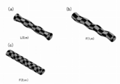
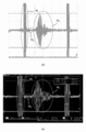
- FIG. 3 shows a conceptual diagram of the vibration of the guide wave.
- the manner of vibration of the guide wave is classified according to the symmetry in the circumferential direction.
- (A) The L (0, m) mode vibrates axisymmetrically.
- (B) The F (1, m) mode has a symmetry of 360 degrees and has high excitation efficiency.
- (C) The F (2, m) mode has 180 degree symmetry, but the excitation efficiency becomes extremely small.
- the L (0, m) mode is axially symmetric, the amplitude of the guide wave in the axial vibration mode is preferably increased if it is vibrated axially. Then, by integrating the signals of the plurality of receivers, only the amplitude of the L (0, m) mode is amplified. Therefore, the amplitude of the excitation signal is increased and the reception sensitivity is improved, and the excitation wave mode can be selected.
- L (0,4) can be isolated from the group velocity of other modes by selecting the frequency band for exciting the guide wave. Sensitivity can be improved and this mode is suitable for measurement.
- two or more ultrasonic transducers 12a and 12b (or 12c and 12d) disposed on the transmission side are pressed against the tube body 10 with substantially the same pressure. By driving, it is possible to obtain an excellent amplification effect that cannot be obtained by simply arranging two or more ultrasonic transducers in the L (0, 4) mode guide wave.
- the S / N ratio of the guide wave received by the reception-type ultrasonic transducer 12 (the transmission-side ultrasonic transducers 12a and 12b (or 12c and 12d) are driven before and after the guide wave is excited).
- the signal intensity ratio) is extremely large, and reception sensitivity can be improved.
- the F (2, m) mode has a small S / N ratio of the received guide wave, and is not suitable for the ultrasonic flowmeter 100 according to the present invention.
- the ultrasonic flowmeter 100 generates an ultrasonic signal suitable for measuring an ultrasonic signal between the tubular body 10 and the ultrasonic transducers 12a to 12d.
- An alignment member 14 for conversion is provided.
- the alignment member 14 efficiently transmits ultrasonic waves generated by driving the ultrasonic transducers 12a and 12b (or 12c and 12d) to the tube body 10 and prevents the tube body 10 from being deformed. It is preferable to provide a curved surface on the contact surface. Further, the contact surface of the alignment member 14 with the tube body 10 is not limited to a curved surface as long as adhesion with the tube body 10 can be ensured.
- An alignment member 14 is disposed between the tubular body 10 through which the fluid flows and the ultrasonic vibrators 12a to 12d, and the tubular body 10 is sandwiched by the alignment member 14 to thereby remove the ultrasonic vibrators 12a and 12b (or 12c and 12d).
- An ultrasonic signal to be excited is efficiently transmitted to the tube body 10, and the ultrasonic signal can be shortened by attenuating the ultrasonic signal, thereby enabling stable measurement. This is because the ultrasonic signal is continuously oscillated, so that the transmitted ultrasonic signal is rapidly attenuated by the matching member 14 to prevent reverberation from overlapping the next ultrasonic signal to be oscillated.
- the alignment member 14 efficiently transmits ultrasonic signals transmitted from the ultrasonic transducers 12a and 12b (or 12c and 12d) to the tube body 10, thereby making it difficult for reverberation to remain.
- the ultrasonic signals from the transducers 12a and 12b (or 12c and 12d) can be quickly attenuated.
- the S / N ratio of the guide wave received by the ultrasonic transducers 12c and 12d (or 12a and 12b) on the receiving side becomes extremely large, and the reception sensitivity is improved. Can be made.
- the tube body 10 has a lower hardness than the ultrasonic transducer 12
- a member having a hardness higher than that of the tube body 10 and a hardness lower than that of the ultrasonic transducer 12 is used for the alignment member 14 according to the present invention.
- CFRP carbon fiber reinforced plastic
- silicon sheet aluminum, ebonite, magnesium, polyphenylene sulfide resin (PPS), or the like
- PPS polyphenylene sulfide resin
- carbon fiber reinforced plastic is preferable as the alignment member 14 according to the present invention because it can efficiently transmit an ultrasonic signal excited from the ultrasonic transducer 12 to the tube body 10.
- the alignment member 14 When carbon fiber reinforced plastic is used as the alignment member 14 according to the present invention, it is preferable to use a member laminated so that the carbon fibers are perpendicular to the surface in contact with the ultrasonic transducer 12. Since the carbon fiber included in the alignment member 14 has such an orientation, an ultrasonic signal transmitted from the ultrasonic transducer 12 is efficiently transmitted to the tube body 10 and also from the ultrasonic transducer 12 on the transmission side. The ultrasonic signal can be quickly attenuated.
- an irregular member such as grease or a gel sheet can be used as the alignment member 14.
- the grease or gel sheet may be disposed on the contact surface of the alignment member 14 with the tubular body 10 in combination with the member having the predetermined shape described above.
- the shape of the alignment member between the tubular body 10 through which the fluid flows and the ultrasonic vibrator is brought close to the R shape on the outer periphery of the tubular body, and the deformation of the tubular body can be prevented by providing and pressing the groove. It is not limited to these.
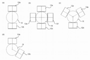
- FIG. 4 is a schematic view showing the arrangement of the ultrasonic transducers 12a and 12b for transmission / reception provided in the tubular body 10 from the cross-sectional direction of the tubular body 10.
- FIG. 4 shows a cross section taken along the line AA ′ of FIG.
- the ultrasonic transducers 12a and 12b are attached to the periphery of the tube body 10 in axial symmetry, and are excited and received in the same phase (in phase).
- (a) a pair of axially symmetric ultrasonic transducers 12 a and 12 b are attached in the vertical direction around the tube body 10.
- the two or more ultrasonic transducers 12a and 12b are provided within a range in which the signal amplification effect and the reception sensitivity improvement effect of the present application can be obtained. It may be arranged asymmetrically around 10 (d). The arrangement of such asymmetric ultrasonic transducers is the same when three or more ultrasonic transducers are arranged.
- the ultrasonic flowmeter 100 In the ultrasonic flowmeter 100 according to the present invention, two sets of ultrasonic transducers 12a to 12d are used on the transmitting side and the receiving side, respectively, and a total of four sets are used, and are attached perpendicularly to the central axis of the tubular body 10.
- the ultrasonic signal By exciting the ultrasonic signal vertically, the ultrasonic signal can be increased to a measurable level. Further, the same effect can be obtained even when there are three or more ultrasonic transducers and one set, for a total of six or more.
- the ultrasonic flowmeter 100 according to the present invention is different from the conventional V-type reflection type (clamp-on type) ultrasonic flowmeter, two or more ultrasonic transducers are arranged on the transmission side, whereby a guide wave is obtained.
- the effect of improving the receiving sensitivity can be obtained by the amplification effect.
- the voltages applied to the two or more ultrasonic transducers 12a and 12b (or 12c and 12d) disposed on the transmission side are in phase (the ultrasonic transducer 12 has the same phase).
- S / N by enlarging the vibration of the ultrasonic wave by exciting the vibration of only the axial vibration mode, particularly the L (0, 4) mode in the tube body 10 by making the driving timing and the vibration magnitude the same. It is possible to increase the ratio and amplify the reception sensitivity.
- the ultrasonic flowmeter 100 since the ultrasonic flowmeter 100 according to the present invention is different from the conventional V-type reflection type ultrasonic flowmeter, the ultrasonic transducers 12a to 12d have the mounting directions on the reception side and the transmission side in parallel. Instead, they may be arranged at different angles. Thereby, it is possible to reduce the influence of the ultrasonic signal (standing wave) transmitted to the storage body described later.
- the ultrasonic flowmeter 100 is provided with a storage body for detachably storing the tube body 10.
- the storage body is, for example, a storage body 20 provided with an opening 22 for observing a fluid flowing through the tube body 10 as shown in FIG. 8, and the outer surface shape of the storage body 20 is curved or tapered to the storage body 20. It is preferable to reduce the standing wave transmitted. This is because if the parallel portion or the straight portion over the entire storage body 20 exists, the storage body 20 resonates and affects the ultrasonic signal received by the ultrasonic transducer 12.
- the storage body 20 in order to make the storage body 20 that houses the tube body 10 detachable, it is preferable that the storage body 20 has a two-part structure that can be opened and closed by the link member 24.
- the ultrasonic flowmeter Once the conventional ultrasonic flowmeter is installed on the tube, the ultrasonic vibrator 12 cannot be replaced unless the tube is cut.
- the ultrasonic flowmeter 100 according to the present invention can be easily attached to the tubular body 10 by disposing the ultrasonic vibrator in the detachable storage body 20, and the position of the tubular body 10 for measuring the flow rate can be adjusted later. It is also possible to change from.
- the ultrasonic transducer is disposed in the storage body 20 so that the distance between the ultrasonic transducers on the transmission side and the reception side can be made constant and can be easily attached and detached.
- the distance L between the ultrasonic transducers 12a and 12c (or 12b and 12d) on the transmission side and the reception side is an important parameter, but by using the container 20 according to the present invention, The ultrasonic transducers 12a and 12c (or 12b and 12d) can be easily arranged.
- the inside of the storage body 20 has a structure in which a sufficient clearance is provided to prevent interference with the tube body 10 and a distance from the outside to the tube body 10 is provided so that it cannot be easily contacted from the outside. This is because the tubular body 10 is not affected by vibration or the like from the outside of the storage body 20.
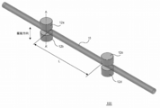
- FIG. 5 is a schematic view showing an ultrasonic flowmeter 200 according to an embodiment of the present invention.
- the ultrasonic flowmeter 200 includes two ultrasonic transducers 12a and 12c (or 12b and 12d) on the outer peripheral surface of the pipe body 10 through which a fluid flows. Each is provided in parallel in the same direction.
- the ultrasonic transducer has a pair of cylindrical shapes, and is disposed in a vertical direction with respect to the tube body 10 in an axially symmetrical manner, and thus vibrates in an axially symmetrical manner.
- One of the two ultrasonic transducers 12a and 12b (or 12c and 12d) functions as a transmission side, and the other functions as a reception side, and the two ultrasonic transducers 12a and 12b (or 12c) are disposed. And 12d) are operated alternately.
- the fluid flow velocity can be obtained from the propagation time difference from the propagation time.
- the ultrasonic vibrators 12a and 12b are provided so as to press the tube body 10 with substantially the same pressure, and are arranged in an axisymmetric manner.
- the child can be driven in the L (0, m) mode in phase and the tube 10 can be vibrated in an axially symmetrical manner. Thereby, the vibration of only the axial vibration mode is excited in the tube body 10, and the vibration of only the axial vibration mode can be transmitted along the fluid flow direction.
- the ultrasonic transducers 12a and 12b (or 12c and 12d) arranged in an axial symmetry on the outer periphery of the tube body 10 are driven in phase.
- the ultrasonic transducers 12a and 12b (or 12c and 12d) arranged in an axially symmetrical manner on the outer periphery of the tube body 10 are driven in the opposite phase to guide the F (1, m) mode. It does not exclude exciting and detecting waves with large amplitudes.
- FIG. 6 is a schematic diagram of an ultrasonic flowmeter 300 in which the receiving directions of the ultrasonic transducers 12a and 12b (or 12c and 12d) are not arranged in parallel but are arranged at different angles.
- the ultrasonic flowmeter 300 when the ultrasonic transducer 12 is disposed in the storage body, it is possible to reduce the influence of an ultrasonic signal (standing wave) transmitted to the storage body. This is to prevent the standing wave from being transmitted in parallel to the storage body.
- an alignment member 14 for converting an ultrasonic signal suitable for measurement is provided between the tubular body 10 and the ultrasonic transducers 12a to 12d.
- the alignment member 14 forms a contact surface with the tubular body in a curved surface in order to prevent the deformation of the tubular body 10, thereby ensuring sufficient contact with the tubular body 10.
- the contact surface with the tubular body 10 may be curved, and grease or the like may be applied, or a gel sheet may be disposed to improve adhesion.
- the alignment member 14 is provided independently for the upper ultrasonic transducers 12a and 12c and the lower ultrasonic transducers 12b and 12d.
- FIG. 7 is a schematic view of the alignment member 14 according to the embodiment of the present invention.
- the alignment member 14 is made of a CFRP aggregate formed by superposing CFRP material pieces 16 in which carbon fibers are arranged in one direction on an epoxy resin.
- the alignment member 14 is configured such that the direction of the carbon fiber of the CFRP aggregate is perpendicular to the tube body 10.
- the alignment member 14 is formed with a curved shape or a groove so as to sandwich the tube body 10 at the lower end where the tube body 10 is sandwiched.
- FIG. 8 is a schematic view of a storage body 20 for detachably storing the tube body 10.
- FIG. 9 is a schematic view showing an internal structure in which the storage body 20 is opened.
- the storage body 20 of the present embodiment includes an opening 22 for observing the fluid flowing through the tube body 10.
- the outer shape of the storage body 20 is a curved or tapered shape that reduces standing waves transmitted to the storage body.
- the storage body 20 includes a hinge 24 for making the tube body 10 removable.
- a storage unit 26 is provided for storing the ultrasonic transducer.
- the tube body 10 has a non-contact portion 28 that contacts only the alignment member 14 and does not contact the storage body 20.
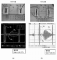
- FIG. 10 shows a comparative example in which PZT is used for the ultrasonic transducers 12a to 12d and one PZT is used for each of the transmitting side and the receiving side (FIG. 10A), and the ultrasonic flow rate of the present invention.
- the data which measured the waveform of the ultrasonic signal in Example 1 (FIG.10 (b)) which uses a pair of PZT for a transmission side and a receiving side like the total 100 are shown.
- the measurement conditions are as follows.
- Tubing material PFA, size 1/8 inch (3.17 ⁇ 1.59)
- Sensor mounting interval 60mm Impulsed pulse; 338 kHz, five-shot alignment member; Grease applied between PZT and tube; Water temperature; Ambient temperature; 25 ° C
- the gain value indicates the ultrasonic waveform of 40 fixed measurement results as (a; 1 PZT) and (b; 1 pair (2) PZT), respectively.
- the waveform W i represents the ultrasonic wave by the ultrasonic transducers of the transmitting side is sent, the previous waveform waveform W p for receiving the guided wave at the receiving side
- a waveform Wo represents a guide wave received on the receiving side.
- Vpp is 120 mV
- Vpp is 792 mV
- the S / N ratio is remarkably improved by disposing two ultrasonic transducers on the transmission side, and the ultrasonic flow rate according to the present invention. It became clear that the sensitivity was greatly improved. This is not a simple predictable effect.
- Example 2 the effect of using the alignment member 14 having a predetermined shape was examined.
- the CFRP aggregate (diameter 7, 1 mm) shown in FIG. 7 is used, and grease is applied between the alignment member 14 and the tube body 10 (FIG. 11A) or a gel sheet is disposed. (FIG. 11 (b)).
- PZT and CFRP aggregate were bonded with an adhesive.
- the received guide The waveform of the wave became sharp and it became clear that it was in a state suitable for flow rate measurement.
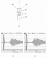
- FIG. 12A is a schematic diagram in which the ultrasonic transducers 12 a and 12 b (or 12 c and 12 d) are arranged on the outer periphery of the tubular body 10.
- FIG. 12B shows the waveform of Example 1 in which the ultrasonic transducers 12a and 12b (or 12c and 12d) are arranged facing the outer periphery of the tubular body 10
- FIG. 12C shows the ultrasonic transducers 12a and 12b.
- Example 3 which has arrange
- the ultrasonic flowmeter according to the present invention is unprecedented and enables highly sensitive flow measurement.
- the ultrasonic flowmeter according to the present invention can be used for measurement of flow velocity used in industry, measurement of fluid in a living body such as a blood vessel, and the like.
Abstract
Priority Applications (5)
| Application Number | Priority Date | Filing Date | Title |
|---|---|---|---|
| EP15799778.4A EP3136061B1 (fr) | 2014-05-28 | 2015-05-27 | Débitmètre à ultrasons |
| CN201580025170.8A CN106461436B (zh) | 2014-05-28 | 2015-05-27 | 超声波流量计 |
| JP2016523542A JP6106338B2 (ja) | 2014-05-28 | 2015-05-27 | 超音波流量計 |
| KR1020167032149A KR101951533B1 (ko) | 2014-05-28 | 2015-05-27 | 초음파 유량계 |
| US15/352,681 US10197424B2 (en) | 2014-05-28 | 2016-11-16 | Ultrasonic flowmeter having transceivers driving and radially pressing the flow tube to increase amplitude of the ultrasonic wave |
Applications Claiming Priority (2)
| Application Number | Priority Date | Filing Date | Title |
|---|---|---|---|
| JP2014-110453 | 2014-05-28 | ||
| JP2014110453 | 2014-05-28 |
Related Child Applications (1)
| Application Number | Title | Priority Date | Filing Date |
|---|---|---|---|
| US15/352,681 Continuation US10197424B2 (en) | 2014-05-28 | 2016-11-16 | Ultrasonic flowmeter having transceivers driving and radially pressing the flow tube to increase amplitude of the ultrasonic wave |
Publications (1)
| Publication Number | Publication Date |
|---|---|
| WO2015182673A1 true WO2015182673A1 (fr) | 2015-12-03 |
Family
ID=54698996
Family Applications (1)
| Application Number | Title | Priority Date | Filing Date |
|---|---|---|---|
| PCT/JP2015/065291 WO2015182673A1 (fr) | 2014-05-28 | 2015-05-27 | Débitmètre à ultrasons |
Country Status (6)
| Country | Link |
|---|---|
| US (1) | US10197424B2 (fr) |
| EP (1) | EP3136061B1 (fr) |
| JP (1) | JP6106338B2 (fr) |
| KR (1) | KR101951533B1 (fr) |
| CN (1) | CN106461436B (fr) |
| WO (1) | WO2015182673A1 (fr) |
Families Citing this family (4)
| Publication number | Priority date | Publication date | Assignee | Title |
|---|---|---|---|---|
| CN107271715B (zh) * | 2017-06-08 | 2019-08-20 | 杭州子午仪器有限公司 | 一种测量管道流体流速的装置及测量方法 |
| JP6532504B2 (ja) * | 2017-07-07 | 2019-06-19 | 株式会社ソニック | 超音波流量計 |
| CN113324603A (zh) * | 2021-04-16 | 2021-08-31 | 浙江纺织服装职业技术学院 | 一种非金属管流通状态的检测装置 |
| GB202202309D0 (en) * | 2022-02-21 | 2022-04-06 | Titan Entpr Ltd | Flow meters |
Citations (1)
| Publication number | Priority date | Publication date | Assignee | Title |
|---|---|---|---|---|
| JP4878653B1 (ja) * | 2011-01-28 | 2012-02-15 | 株式会社アツデン | 超音波流量測定装置 |
Family Cites Families (27)
| Publication number | Priority date | Publication date | Assignee | Title |
|---|---|---|---|---|
| US3964308A (en) * | 1973-09-04 | 1976-06-22 | Scarpa Laboratories, Inc. | Ultrasonic flowmeter |
| US4164865A (en) * | 1977-02-22 | 1979-08-21 | The Perkin-Elmer Corporation | Acoustical wave flowmeter |
| US4628725A (en) * | 1985-03-29 | 1986-12-16 | Schlumberger Technology Corporation | Apparatus and method for analyzing a fluid that includes a liquid phase, contained in a tubular conduit |
| US5052230A (en) * | 1988-07-08 | 1991-10-01 | Flowtec Ag | Method and arrangement for flow rate measurement by means of ultrasonic waves |
| US5719329B1 (en) * | 1995-12-28 | 1999-11-16 | Univ Ohio | Ultrasonic measuring system and method of operation |
| JPH10122923A (ja) | 1996-10-15 | 1998-05-15 | Tokyo Keiso Co Ltd | 超音波流量計 |
| US6412354B1 (en) * | 1999-12-16 | 2002-07-02 | Halliburton Energy Services, Inc. | Vibrational forced mode fluid property monitor and method |
| US6601458B1 (en) * | 2000-03-07 | 2003-08-05 | Weatherford/Lamb, Inc. | Distributed sound speed measurements for multiphase flow measurement |
| US20030115969A1 (en) * | 2000-12-15 | 2003-06-26 | Izumi Engineering Laboratory Co., Ltd | Ultrasonic flow meter |
| GB0308222D0 (en) * | 2003-04-10 | 2003-05-14 | Univ Cranfield | A flowmeter |
| JP4233445B2 (ja) * | 2003-12-24 | 2009-03-04 | 旭有機材工業株式会社 | 超音波流量計 |
| JP2006349439A (ja) * | 2005-06-15 | 2006-12-28 | Nippon Flow Cell Kk | 超音波流量計 |
| JP5142350B2 (ja) | 2006-04-11 | 2013-02-13 | 独立行政法人産業技術総合研究所 | 流量測定装置 |
| GB2447691B (en) * | 2007-03-23 | 2009-10-28 | Schlumberger Holdings | Flow measuring apparatus and method |
| JP5201525B2 (ja) * | 2007-10-29 | 2013-06-05 | 独立行政法人産業技術総合研究所 | 流量測定装置 |
| JP5622383B2 (ja) * | 2009-11-26 | 2014-11-12 | 株式会社アツデン | 超音波式流量測定装置 |
| US8997581B2 (en) | 2009-11-30 | 2015-04-07 | National Institute of Advanced Industrial Science and Technology Atsuden Co., Ltd. | Flow rate measuring device |
| JP5655194B2 (ja) * | 2010-01-29 | 2015-01-21 | 独立行政法人産業技術総合研究所 | 流量測定装置 |
| JP4875780B2 (ja) * | 2010-06-22 | 2012-02-15 | 株式会社泉技研 | 超音波流量測定装置及び超音波流量測定方法 |
| US7980127B1 (en) * | 2010-11-12 | 2011-07-19 | Hou Yao-Sung | Flow meter |
| EP2686643A4 (fr) | 2011-03-18 | 2014-09-10 | Soneter Llc | Procédés et appareil pour la mesure d'un écoulement de fluide |
| JP5659956B2 (ja) * | 2011-06-03 | 2015-01-28 | パナソニックIpマネジメント株式会社 | 超音波送受波器及び超音波流量計 |
| US8714030B1 (en) * | 2011-09-10 | 2014-05-06 | Strain Measurement Devices, Inc. | Non-invasive tranducers for ultrasonic transit time flow meters |
| JP4991972B1 (ja) * | 2012-03-09 | 2012-08-08 | 株式会社アツデン | 超音波流量測定装置 |
| JP4940384B1 (ja) * | 2012-01-13 | 2012-05-30 | 株式会社アツデン | 超音波流量測定装置 |
| JP6101922B2 (ja) * | 2012-06-05 | 2017-03-29 | パナソニックIpマネジメント株式会社 | 超音波流量計測ユニット及びその製造方法 |
| GB2504288A (en) * | 2012-07-24 | 2014-01-29 | Titan Entpr Ltd | Acoustic flow meter |
-
2015
- 2015-05-27 CN CN201580025170.8A patent/CN106461436B/zh active Active
- 2015-05-27 JP JP2016523542A patent/JP6106338B2/ja active Active
- 2015-05-27 WO PCT/JP2015/065291 patent/WO2015182673A1/fr active Application Filing
- 2015-05-27 KR KR1020167032149A patent/KR101951533B1/ko active IP Right Grant
- 2015-05-27 EP EP15799778.4A patent/EP3136061B1/fr active Active
-
2016
- 2016-11-16 US US15/352,681 patent/US10197424B2/en active Active
Patent Citations (1)
| Publication number | Priority date | Publication date | Assignee | Title |
|---|---|---|---|---|
| JP4878653B1 (ja) * | 2011-01-28 | 2012-02-15 | 株式会社アツデン | 超音波流量測定装置 |
Also Published As
| Publication number | Publication date |
|---|---|
| CN106461436B (zh) | 2019-12-24 |
| US10197424B2 (en) | 2019-02-05 |
| KR20160145175A (ko) | 2016-12-19 |
| JP6106338B2 (ja) | 2017-03-29 |
| EP3136061B1 (fr) | 2020-12-09 |
| US20170059379A1 (en) | 2017-03-02 |
| CN106461436A (zh) | 2017-02-22 |
| EP3136061A1 (fr) | 2017-03-01 |
| KR101951533B1 (ko) | 2019-02-22 |
| JPWO2015182673A1 (ja) | 2017-06-01 |
| EP3136061A4 (fr) | 2017-12-06 |
Similar Documents
| Publication | Publication Date | Title |
|---|---|---|
| JP6106338B2 (ja) | 超音波流量計 | |
| US10458871B2 (en) | Apparatus and method for measuring the pressure inside a pipe or container | |
| US7069793B2 (en) | Ultrasonic flow meter and ultrasonic sensor | |
| JP4233445B2 (ja) | 超音波流量計 | |
| JP2003075219A (ja) | クランプオン型超音波流量計 | |
| WO2014016315A1 (fr) | Débitmètre acoustique | |
| JP2014085255A (ja) | 超音波流量計製造方法及びこれにより製造した超音波流量計並びに超音波流量計を備える流体制御装置 | |
| JP2015232519A (ja) | クランプオン式超音波流量計及び流量の計測方法 | |
| JP5142350B2 (ja) | 流量測定装置 | |
| JP5827809B2 (ja) | 超音波探触子及び管状対象物の周長測定方法 | |
| JP2009109299A (ja) | 流量測定装置 | |
| JP2015230260A (ja) | 超音波流量計及び超音波流量計の取付方法 | |
| JP2011007763A (ja) | 超音波流量計 | |
| JP2005189002A (ja) | 流量測定システム | |
| JP6149250B2 (ja) | 超音波流量計 | |
| US20200116671A1 (en) | Acoustic sensor | |
| JP3144177B2 (ja) | 渦流量計 | |
| JP2006349439A (ja) | 超音波流量計 | |
| JP2003139591A (ja) | 超音波流量計 | |
| JP3639570B2 (ja) | 超音波送受波器 | |
| JP2003014513A (ja) | 超音波流量計 | |
| JP2883057B2 (ja) | 超音波送受波器 | |
| JP2010249788A (ja) | 気体用超音波流量計 | |
| JP2012242090A (ja) | 超音波流量計 | |
| JP2002250644A (ja) | クランプオン形超音波流量計における超音波送受波器 |
Legal Events
| Date | Code | Title | Description |
|---|---|---|---|
| 121 | Ep: the epo has been informed by wipo that ep was designated in this application |
Ref document number: 15799778 Country of ref document: EP Kind code of ref document: A1 |
|
| ENP | Entry into the national phase |
Ref document number: 2016523542 Country of ref document: JP Kind code of ref document: A |
|
| ENP | Entry into the national phase |
Ref document number: 20167032149 Country of ref document: KR Kind code of ref document: A |
|
| REEP | Request for entry into the european phase |
Ref document number: 2015799778 Country of ref document: EP |
|
| WWE | Wipo information: entry into national phase |
Ref document number: 2015799778 Country of ref document: EP |
|
| NENP | Non-entry into the national phase |
Ref country code: DE |