WO2015182395A1 - 被覆銅粒子及びその製造方法 - Google Patents
被覆銅粒子及びその製造方法 Download PDFInfo
- Publication number
- WO2015182395A1 WO2015182395A1 PCT/JP2015/063880 JP2015063880W WO2015182395A1 WO 2015182395 A1 WO2015182395 A1 WO 2015182395A1 JP 2015063880 W JP2015063880 W JP 2015063880W WO 2015182395 A1 WO2015182395 A1 WO 2015182395A1
- Authority
- WO
- WIPO (PCT)
- Prior art keywords
- copper
- coated copper
- copper particles
- reaction
- solvent
- Prior art date
Links
Images


Classifications
-
- B—PERFORMING OPERATIONS; TRANSPORTING
- B22—CASTING; POWDER METALLURGY
- B22F—WORKING METALLIC POWDER; MANUFACTURE OF ARTICLES FROM METALLIC POWDER; MAKING METALLIC POWDER; APPARATUS OR DEVICES SPECIALLY ADAPTED FOR METALLIC POWDER
- B22F1/00—Metallic powder; Treatment of metallic powder, e.g. to facilitate working or to improve properties
- B22F1/10—Metallic powder containing lubricating or binding agents; Metallic powder containing organic material
- B22F1/102—Metallic powder coated with organic material
-
- B—PERFORMING OPERATIONS; TRANSPORTING
- B22—CASTING; POWDER METALLURGY
- B22F—WORKING METALLIC POWDER; MANUFACTURE OF ARTICLES FROM METALLIC POWDER; MAKING METALLIC POWDER; APPARATUS OR DEVICES SPECIALLY ADAPTED FOR METALLIC POWDER
- B22F9/00—Making metallic powder or suspensions thereof
- B22F9/16—Making metallic powder or suspensions thereof using chemical processes
- B22F9/18—Making metallic powder or suspensions thereof using chemical processes with reduction of metal compounds
- B22F9/24—Making metallic powder or suspensions thereof using chemical processes with reduction of metal compounds starting from liquid metal compounds, e.g. solutions
-
- B—PERFORMING OPERATIONS; TRANSPORTING
- B22—CASTING; POWDER METALLURGY
- B22F—WORKING METALLIC POWDER; MANUFACTURE OF ARTICLES FROM METALLIC POWDER; MAKING METALLIC POWDER; APPARATUS OR DEVICES SPECIALLY ADAPTED FOR METALLIC POWDER
- B22F9/00—Making metallic powder or suspensions thereof
- B22F9/16—Making metallic powder or suspensions thereof using chemical processes
- B22F9/30—Making metallic powder or suspensions thereof using chemical processes with decomposition of metal compounds, e.g. by pyrolysis
- B22F9/305—Making metallic powder or suspensions thereof using chemical processes with decomposition of metal compounds, e.g. by pyrolysis of metal carbonyls
-
- H—ELECTRICITY
- H01—ELECTRIC ELEMENTS
- H01B—CABLES; CONDUCTORS; INSULATORS; SELECTION OF MATERIALS FOR THEIR CONDUCTIVE, INSULATING OR DIELECTRIC PROPERTIES
- H01B1/00—Conductors or conductive bodies characterised by the conductive materials; Selection of materials as conductors
- H01B1/20—Conductive material dispersed in non-conductive organic material
- H01B1/22—Conductive material dispersed in non-conductive organic material the conductive material comprising metals or alloys
-
- H—ELECTRICITY
- H01—ELECTRIC ELEMENTS
- H01B—CABLES; CONDUCTORS; INSULATORS; SELECTION OF MATERIALS FOR THEIR CONDUCTIVE, INSULATING OR DIELECTRIC PROPERTIES
- H01B13/00—Apparatus or processes specially adapted for manufacturing conductors or cables
-
- H—ELECTRICITY
- H01—ELECTRIC ELEMENTS
- H01B—CABLES; CONDUCTORS; INSULATORS; SELECTION OF MATERIALS FOR THEIR CONDUCTIVE, INSULATING OR DIELECTRIC PROPERTIES
- H01B5/00—Non-insulated conductors or conductive bodies characterised by their form
-
- B—PERFORMING OPERATIONS; TRANSPORTING
- B22—CASTING; POWDER METALLURGY
- B22F—WORKING METALLIC POWDER; MANUFACTURE OF ARTICLES FROM METALLIC POWDER; MAKING METALLIC POWDER; APPARATUS OR DEVICES SPECIALLY ADAPTED FOR METALLIC POWDER
- B22F1/00—Metallic powder; Treatment of metallic powder, e.g. to facilitate working or to improve properties
- B22F1/05—Metallic powder characterised by the size or surface area of the particles
- B22F1/054—Nanosized particles
-
- B—PERFORMING OPERATIONS; TRANSPORTING
- B22—CASTING; POWDER METALLURGY
- B22F—WORKING METALLIC POWDER; MANUFACTURE OF ARTICLES FROM METALLIC POWDER; MAKING METALLIC POWDER; APPARATUS OR DEVICES SPECIALLY ADAPTED FOR METALLIC POWDER
- B22F2301/00—Metallic composition of the powder or its coating
- B22F2301/10—Copper
-
- B—PERFORMING OPERATIONS; TRANSPORTING
- B22—CASTING; POWDER METALLURGY
- B22F—WORKING METALLIC POWDER; MANUFACTURE OF ARTICLES FROM METALLIC POWDER; MAKING METALLIC POWDER; APPARATUS OR DEVICES SPECIALLY ADAPTED FOR METALLIC POWDER
- B22F9/00—Making metallic powder or suspensions thereof
- B22F9/16—Making metallic powder or suspensions thereof using chemical processes
- B22F9/30—Making metallic powder or suspensions thereof using chemical processes with decomposition of metal compounds, e.g. by pyrolysis
-
- Y—GENERAL TAGGING OF NEW TECHNOLOGICAL DEVELOPMENTS; GENERAL TAGGING OF CROSS-SECTIONAL TECHNOLOGIES SPANNING OVER SEVERAL SECTIONS OF THE IPC; TECHNICAL SUBJECTS COVERED BY FORMER USPC CROSS-REFERENCE ART COLLECTIONS [XRACs] AND DIGESTS
- Y02—TECHNOLOGIES OR APPLICATIONS FOR MITIGATION OR ADAPTATION AGAINST CLIMATE CHANGE
- Y02E—REDUCTION OF GREENHOUSE GAS [GHG] EMISSIONS, RELATED TO ENERGY GENERATION, TRANSMISSION OR DISTRIBUTION
- Y02E60/00—Enabling technologies; Technologies with a potential or indirect contribution to GHG emissions mitigation
- Y02E60/30—Hydrogen technology
- Y02E60/32—Hydrogen storage
Definitions
- the present invention relates to coated copper particles and a method for producing the same.
- Gold and silver which are noble metals, have characteristics that are relatively difficult to be oxidized. Therefore, when a metal fine particle dispersion is prepared, the contained metal fine particles should be maintained without forming an oxide film on the surface. Is easy.
- copper has a characteristic that it is relatively easily oxidized, and the tendency becomes more remarkable in relation to the size effect and the specific surface area particularly when the fine copper particles having a particle diameter of 200 nm or less are obtained. .
- the contained copper fine particles are in a state where the surface is covered with an oxide film in a short time, and the thickness of the oxide film increases with time, and the majority of the particle size of the copper fine particles Is often converted into an oxide film of copper oxide.
- the activity of the particle surface is in a very high state, and even in a method of heating and baking under an inert atmosphere such as nitrogen gas or under vacuum conditions, a trace amount present in the atmosphere Oxidation proceeds with oxygen, which may inhibit sintering of copper fine particles. Further, an increase in the oxide film during firing may cause volume shrinkage during reduction and reduction in firing density when reduction firing is performed using hydrogen gas or the like at the final stage of firing.
- the melting point drop due to the size effect is 1,064 ° C. as a simple substance when gold is taken as an example, but when the particle diameter is about 2 nm, it becomes about 300 ° C., and the melting point decreases to a temperature that can be used for electronic materials.
- the particle diameter exceeds 20 nm. Therefore, if the particle size is a single nano size of about 2 nm, a melting point drop can be sufficiently expected.
- a surface protective agent that prevents oxidation is essential.
- the required amount of the surface protective agent is several times the volume of copper, which causes a significant volume shrinkage during sintering, making it difficult to obtain a high-density sintered body.
- a method for controlling the generation rate of metal nuclei as a solute has been devised. For example, by gradually releasing substances necessary for particle growth from a reservoir (solid or metal chelate), the degree of supersaturation of the solution is controlled, and new nucleation during particle growth is suppressed. Only the nuclei produced at the very beginning after the grain growth period are grown, so that particles exhibiting monodispersity can be produced.
- a solid or complex compound with sufficiently low solubility or dissolution rate is selected as a method for selecting a reservoir for supplying a solute during particle growth.
- a technique for producing copper fine particles by thermally decomposing a complex compound derived from copper formate is known.
- the decomposition temperature of copper formate is about 220 ° C., but the decomposition temperature can be lowered by forming a complex structure.
- Japanese Patent Application Laid-Open No. 2011-032558 proposes a method for producing metal fine particles by thermal decomposition at 100 ° C. using a complex compound of an amino alcohol that functions as a bidentate ligand.
- Japanese Patent Application Laid-Open No. 2008-013466 or Japanese Patent Application Laid-Open No. 2008-031104 proposes a method for producing metal fine particles by thermal decomposition at 120 ° C. using a complex compound of an aliphatic amine functioning as a monodentate ligand. Yes.
- a method of controlling the particle size by limiting the metal nuclei incorporated into the growth nuclei in a micro reaction field using a surfactant has been devised.
- a method for producing metal or metal oxide fine particles by a reverse micelle method using nano-sized water droplets stably dispersed in an organic solvent by a surfactant as a reaction field has been proposed (for example, JP-A-08-143916). No., JP-A-2009-082828, and Japanese Patent No. 3900414).
- the decomposition temperature of the complex compound is too low, so that a large amount of metal nuclei are generated at an accelerated rate due to heat generated during decomposition, and the copper contained in the reaction solution Since the concentration is relatively high at 1.0 to 2.4 mol / L, particle growth is likely to occur due to the aggregation mechanism, and coarse particles are generated, so that the yield tends to be low. Further, in the technique described in Japanese Patent Application Laid-Open No. 2008-013466 or Japanese Patent Application Laid-Open No.
- the aliphatic amine constituting the copper formate complex simultaneously serves as a dispersion protective agent for metal fine particles, so that particle growth is prevented. It is difficult to produce, and it is difficult to produce copper particles having a particle size of 20 nm to submicron.
- a nucleation is generated to perform reduction while partially dissolving with an organic carboxylic acid using a solid copper compound such as copper oxide having low solubility as a reservoir.
- the speed is limited, and agglomeration at the nucleus growth stage is less likely to occur as compared with a dissolution system such as that disclosed in JP2011-032558A.
- the nucleation time is long, and the carbon chain of the carboxylic acid that is coated is short, so that sufficient interparticle repulsion cannot be obtained. Is difficult to produce, and the surface tends to be oxidized copper particles.
- the micelle is stabilized by using a large amount of a surfactant.
- the size of the reaction field is limited, it is difficult to produce particles having a size of 20 nm or more.
- the reverse micelle method is difficult to increase the concentration of the copper compound in the reaction solution, and is not suitable for producing a large amount of particles.
- the present invention solves the problems of the prior art, and is difficult to achieve with the prior art, coated copper particles having both excellent oxidation resistance and sinterability, low heat treatment temperature, low oxygen It aims at providing the manufacturing method which can obtain the covering copper particle in an environment.
- the present inventors have appropriately set the difference in SP value between the solvent contained in the reaction solution and the amino alcohol that is the complexing agent, so that a homogeneous system can be obtained at the initial stage of the reaction.
- the reaction system can be configured so as to form a two-layer separation structure in the middle of the reaction, whereby high-quality coated copper particles can be produced efficiently.
- the present invention includes the following aspects. (1) Obtaining a reaction liquid containing copper formate, amino alcohol, aliphatic carboxylic acid having an aliphatic group having 5 or more carbon atoms, and a solvent, and thermally decomposing a complex compound formed in the reaction liquid to obtain copper metal A ⁇ SP value that is a difference in SP value between an amino alcohol and a solvent is 4.2 or more, and a method for producing coated copper particles whose surface is coated with an aliphatic carboxylic acid. (2) The method for producing coated copper particles according to (1), wherein the amino alcohol has an SP value of 11.0 or more. (3) The method for producing coated copper particles according to (1) or (2), wherein the temperature of the thermal decomposition treatment is 100 ° C. to 130 ° C.
- the average primary particle diameter D SEM by SEM observation is 0.02 to 0.2 ⁇ m, and the fluctuation of the particle size distribution Coated copper particles having a coefficient (standard deviation SD / average primary particle diameter D SEM ) of 0.1 to 0.5.
- the coated copper particles have a D XRD / D SEM of 0.25 to 1.00.
- a conductive composition for screen printing comprising coated copper particles obtained by the method for producing coated copper particles according to any one of (1) to (6) and a medium.
- a conductive composition for inkjet printing comprising coated copper particles obtained by the method for producing coated copper particles according to any one of (1) to (6) and a medium.
- a circuit-formed product comprising a substrate and a wiring pattern that is a heat-treated product of the conductive composition according to (9) or (10) disposed on the substrate.
- a coated copper particle having both excellent oxidation resistance and sinterability, which has been difficult to achieve with the prior art, and a production method capable of obtaining the coated copper particle in a low heat treatment temperature and low oxygen environment can be provided.
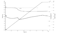
- FIG. 2 is TG-DTA analysis data of coated copper particles produced in Example 1.
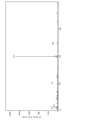
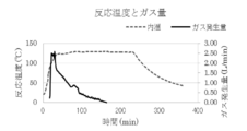
- FIG. 2 is a plot of the reaction temperature and total gas generation during the synthesis of Example 1.
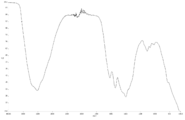
- 2 is FT-IR analysis data of a fraction that flows out during the synthesis of Example 1.
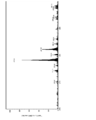
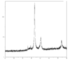
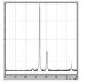
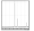
- 3 is XRD data of coated copper particles produced in Reference Example 2.
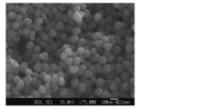
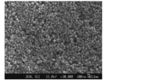
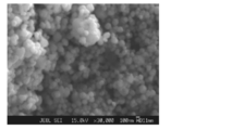
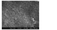
- 2 is an SEM observation image of coated copper particles produced in Example 1.
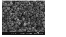
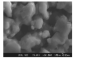
- FIG. 3 is an SEM observation image of coated copper particles produced in Example 2.
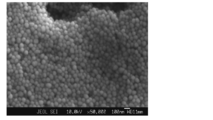
- 4 is a SEM observation image of coated copper particles produced in Example 4.
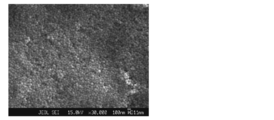
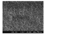
- 3 is an SEM observation image of coated copper particles produced in Comparative Example 1.
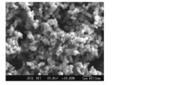
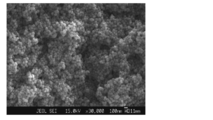
- 4 is an SEM observation image of coated copper particles produced in Comparative Example 2.
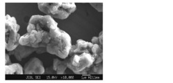
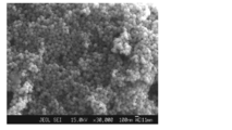
- 4 is a SEM observation image of coated copper particles produced in Comparative Example 3.
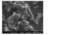
- 6 is a SEM observation image of coated copper particles produced in Comparative Example 4.
- 6 is a SEM observation image of coated copper particles produced in Comparative Example 5.
- 6 is a SEM observation image of coated copper particles produced in Example 5.
- 7 is an SEM observation image of coated copper particles produced in Example 6.
- FIG. 6 is an enlarged SEM observation image of coated copper particles produced in Example 6.
- FIG. 6 is an SEM observation image of coated copper particles produced in Example 7.
- 6 is an enlarged SEM observation image of coated copper particles produced in Example 7.
- FIG. It is a SEM observation image of the covering copper particle produced in Example 8.
- 10 is an enlarged SEM observation image of coated copper particles produced in Example 8.
- 10 is an SEM observation image of coated copper particles produced in Example 9.
- 10 is an enlarged SEM observation image of coated copper particles produced in Example 9.
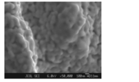
- 2 is an enlarged SEM observation image of coated copper particles produced in Example 1.
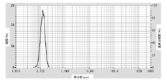
- FIG. It is a particle size distribution measurement data of the coated copper particles produced in Example 1.
- 7 is XRD data of coated copper particles produced in Comparative Example 6.
- FIG. 7 is XRD data of coated copper particles produced in Comparative Example 7.
- FIG. 7 is an SEM observation image of coated copper particles produced in Comparative Example 6. It is a SEM observation image of the sintered film which paste-coated the copper particle produced by the comparative example 6, and baked it at 500 degreeC and 1 hour by nitrogen atmosphere. 2 is an SEM observation image of coated copper particles produced in Example 1.
- FIG. It is a SEM observation image of the sintered film which baked copper paste A which made the covering copper particle produced in Example 1 into paste at 350 degreeC for 1 hour in nitrogen atmosphere. It is a cross-sectional SEM image of a copper paste A baking film
- membrane. 10 is a SEM observation image of coated copper particles produced in Comparative Example 7.
- FIG. 6 is a diagram showing carbon atoms in XPS outermost surface composition analysis data of Test Example 2.
- FIG. 5 is a diagram showing oxygen atoms in XPS outermost surface composition analysis data of Test Example 2.
- FIG. 5 is a diagram showing copper atoms in XPS outermost surface composition analysis data of Test Example 2.
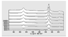
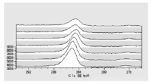
- FIG. 5 is a diagram showing carbon atoms in XPS outermost surface composition analysis data of Test Example 3.
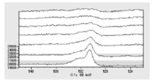
- FIG. 5 is a diagram showing oxygen atoms in XPS outermost surface composition analysis data of Test Example 3.
- FIG. 5 is a diagram showing copper atoms in XPS outermost surface composition analysis data of Test Example 3.
- FIG. 6 is a graph showing the distribution of carbon atoms in the XPS-DepthProfile composition analysis data of Test Example 2.
- FIG. 6 is a diagram showing the distribution of oxygen atoms in the XPS-DepthProfile composition analysis data of Test Example 2.
- FIG. 6 is a diagram showing a distribution of copper atoms in XPS-DepthProfile composition analysis data of Test Example 2.
- FIG. 6 is a graph showing the distribution of carbon atoms in the XPS-DepthProfile composition analysis data of Test Example 3.
- 6 is a diagram showing the distribution of oxygen atoms in the XPS-DepthProfile composition analysis data of Test Example 3.
- 6 is a diagram showing a distribution of copper atoms in XPS-DepthProfile composition analysis data of Test Example 3.
- FIG. 6 is a diagram showing the distribution of oxygen atoms in the XPS-DepthProfile composition analysis data of Test Example 3.
- the term “process” is not limited to an independent process, and is included in the term if the intended purpose of the process is achieved even when it cannot be clearly distinguished from other processes.
- a numerical range indicated by using “to” indicates a range including the numerical values described before and after “to” as the minimum value and the maximum value, respectively.
- the content of each component in the composition means the total amount of the plurality of substances present in the composition unless there is a specific notice when there are a plurality of substances corresponding to each component in the composition.
- the method for producing coated copper particles of the present embodiment includes obtaining a reaction solution containing copper formate, amino alcohol, aliphatic carboxylic acid having an aliphatic group having 5 or more carbon atoms, and a solvent, and a complex formed in the reaction solution.
- the surface was coated with an aliphatic carboxylic acid having a ⁇ SP value of 4.2 or more, which is a difference in SP value between the aminoalcohol and the solvent. It is a manufacturing method of a covering copper particle.
- the thermal decomposition and reduction reaction of the copper formate complex proceeds in the liquid phase, and as the reaction proceeds, amino alcohol that is incompatible with this is released from the copper formate complex into the reaction solvent.
- a new reaction field similar to Water-in-Oil Emulsion is formed. Reduced copper particles with excellent oxidation resistance and sinterability, controlled particle size, and uniform particle size are generated by the progress of the nucleus growth reaction while continuously generating copper metal nuclei in the reaction field. It is thought that it is generated.
- supply of a solute is controlled by appropriately controlling the thermal decomposition rate of the copper formate complex. Thereby, it is considered that the growth of metal nuclei is controlled and reduced copper particles having a more uniform particle size are generated.
- the reduced copper particles produced by the physical adsorption are coated with high density.
- the coated copper particles produced in this way are composed of reduced copper particles with almost no oxide film, and the surface is coated with aliphatic carboxylic acid by physical adsorption, so it has an excellent balance between oxidation resistance and sinterability. It is thought that there is.
- covers the copper particle is removed at the temperature of 400 degrees C or less.
- the coated copper particles can be sintered in a low oxygen atmosphere that can be achieved by means such as nitrogen substitution. Therefore, with conventional copper particles that require a reducing atmosphere for sintering, they are also effectively used for sites that have been difficult to apply, for example, sites where hydrogen embrittlement or alteration due to reaction with hydrogen becomes a problem. be able to. Moreover, since it can sinter using existing facilities, such as a nitrogen substitution reflow furnace, it is excellent also in the point of economical efficiency.
- the reaction solution used in the method for producing the coated copper particles of the present embodiment includes copper formate, at least one amino alcohol, and at least one aliphatic carboxylic acid having an aliphatic group having 5 or more carbon atoms, And a solvent.
- the reaction solution may further contain other additives as required.
- Copper formate is composed of divalent copper ions and 2 moles of formate ions per 1 mole of copper ions. Copper formate may be anhydrous or hydrated. In addition, copper formate may be a commercially available product or a newly prepared one. A method for thermally reducing copper formate to obtain fine particles of reduced copper is disclosed in, for example, Japanese Patent Publication No. 61-19682. Formic acid is different from ordinary carboxylic acid and has reducibility. Therefore, when copper formate is thermally decomposed, divalent copper ions can be reduced. For example, anhydrous copper formate is known to thermally decompose at 210 ° C. to 250 ° C. to produce metallic copper when heated in an inert gas.
- the content of copper formate in the reaction solution is not particularly limited and can be appropriately selected according to the purpose and the like.
- the content of copper formate in the reaction solution is preferably 1.0 to 2.5 mol / liter, more preferably 1.5 to 2.5 mol / liter, for example, from the viewpoint of production efficiency. It is particularly preferably 2.0 to 2.5 mol / liter.
- the amino alcohol is not particularly limited as long as it is an alcohol compound having at least one amino group and can form a complex compound with copper formate. Due to the presence of amino alcohol in the reaction solution, a complex compound can be formed from copper formate and solubilized in a solvent.
- the amino alcohol is preferably a monoamino monoalcohol compound, and more preferably a monoamino monoalcohol compound in which the amino group is unsubstituted.
- the amino alcohol is also preferably a monodentate monoamino monoalcohol compound.
- the boiling point of amino alcohol is not particularly limited, but is preferably higher than the reaction temperature of the thermal decomposition treatment. Specifically, the boiling point of amino alcohol is preferably 120 ° C. or higher, and more preferably 130 ° C. or higher.
- the upper limit of the boiling point is not particularly limited, and is, for example, 400 ° C. or lower, preferably 300 ° C. or lower.
- the amino alcohol has an SP value of preferably 11.0 or more, more preferably 12.0 or more, and further preferably 13.0 or more from the viewpoint of polarity.
- the upper limit of the SP value of aminoalcohol is not particularly limited, and is, for example, 18.0 or less, preferably 17.0 or less.
- the SP value in this specification is based on the definition of Hildebrand. According to the report, the SP value is the square root of intermolecular bonding energy E 1 per sample 1mL at 25 ° C..
- the SP value was calculated by the method described in the “Japan Petroleum Institute website” (http://sekiyu-gakkai.or.jp/jp/dictionary/petdicsolvent.html#solubility2). Specifically, it is calculated as follows.
- Intermolecular bonding energy E 1 is a value obtained by subtracting the gas energy from the latent heat of vaporization.
- the latent heat of vaporization Hb is given by the following equation as the boiling point Tb of the sample.
- Hb 21 ⁇ (273 + Tb) From this Hb value, the molar latent heat of vaporization H 25 at 25 ° C. is obtained by the following equation.
- H 25 Hb ⁇ [1 + 0.175 ⁇ (Tb ⁇ 25) / 100]
- Molar latent heat of vaporization H 25 intermolecular bonding energy E from is determined by the following equation.
- E H 25 -596
- Intermolecular bonding energy E 1 per sample 1mL from intermolecular bonding energy E is calculated by the following equation.
- E 1 E ⁇ D / Mw
- D the density of the sample
- Mw the molecular weight of the sample
- SP value is obtained from E 1 by the following equation.
- SP (E 1 ) 1/2 Note that a solvent containing OH groups needs to be corrected by +1 for each OH group. [For example, Mitsubishi Oil Technology, No. 42, p3, p11 (1989)]
- amino alcohols include 2-aminoethanol (boiling point: 170 ° C., SP value: 14.54), 3-amino-1-propanol (boiling point: 187 ° C., SP value: 13.45), 5-amino -1-pentanol (boiling point: 245 ° C., SP value: 12.78), DL-1-amino-2-propanol (boiling point: 160 ° C., SP value: 12.74), N-methyldiethanolamine (boiling point: 247) C., SP value: 13.26) and the like are exemplified, and at least one selected from the group consisting of these is preferable.
- Amino alcohols may be used singly or in combination of two or more.
- the content of amino alcohol in the reaction solution is not particularly limited and can be appropriately selected according to the purpose and the like.
- the content of amino alcohol is, for example, preferably in the range of 1.5 to 4.0 times mol, more preferably in the range of 1.5 to 3.0 times mol with respect to the copper ions in the reaction solution.
- the content of amino alcohol is 1.5 times mol or more with respect to copper ions, sufficient solubility of copper formate can be obtained, and the time required for the reaction can be shortened.
- the contamination of the produced coated copper particles can be suppressed when the amount is 4.0 times mol or less.
- the aliphatic carboxylic acid is not particularly limited as long as it is a long-chain aliphatic carboxylic acid having an aliphatic group having 5 or more carbon atoms.
- the aliphatic group may be linear or branched, and may be either a saturated aliphatic group or an unsaturated aliphatic group.
- the aliphatic group has 5 or more carbon atoms, preferably 5 or more and 17 or less, and more preferably 7 or more and 17 or less. When the aliphatic group has 5 or more carbon atoms, the variation rate that serves as an index of the particle size distribution tends to be small.
- carboxylic acids having a long carbon chain have a strong associative power and contribute to stabilization of the phase similar to the water-in-oil emulsion which is a micro reaction field, so that copper particles having a uniform particle diameter can be efficiently produced. It is done.
- the boiling point of the aliphatic carboxylic acid is preferably higher than the temperature of the thermal decomposition treatment.
- the boiling point of the aliphatic carboxylic acid is preferably 120 ° C. or higher, and more preferably 130 ° C. or higher.
- the upper limit of the boiling point is not particularly limited, and is, for example, 400 ° C. or lower. There exists a tendency for the sinterability of a covering copper particle to improve more that a boiling point is 400 degrees C or less.
- aliphatic carboxylic acid examples include oleic acid, linoleic acid, stearic acid, heptadecanoic acid, lauric acid, and octanoic acid, and are preferably at least one selected from the group consisting of these.
- the aliphatic carboxylic acid may be used alone or in combination of two or more.
- the content of the aliphatic carboxylic acid in the reaction solution is not particularly limited and can be appropriately selected according to the purpose and the like.
- the content of the aliphatic carboxylic acid is, for example, preferably in the range of 2.5 to 25 mol%, more preferably in the range of 5.0 to 15 mol% with respect to the copper ions in the reaction solution. There exists a tendency which can suppress the viscosity raise of a reaction system as content of aliphatic carboxylic acid is 25 mol% or less with respect to a copper ion.
- the solvent constituting the reaction solution is not particularly limited as long as it is selected so that the reduction reaction with formic acid is not excessively inhibited and the ⁇ SP value, which is the difference in SP value from amino alcohol, is 4.2 or more. It can select suitably from the organic solvent used.
- the ⁇ SP value which is the difference between the SP value of the amino alcohol and the SP value of the solvent, is 4.2 or more, coated copper particles having a narrow particle size distribution and a uniform particle diameter are obtained. It is done.
- the ⁇ SP value is 4.2 or more, preferably 4.5 or more, more preferably 5.0 or more, from the viewpoint of the reaction field formability and the quality of the coated copper particles.
- the upper limit of the ⁇ SP value is not particularly limited.
- the ⁇ SP value is 11.0 or less, and preferably 10.0 or less.
- the SP value of the solvent is selected so that the ⁇ SP value is 4.2 or more, but the SP value of the solvent is preferably smaller than the SP value of amino alcohol.
- the SP value of the solvent is preferably 11.0 or less, and more preferably 10.0 or less.
- the lower limit of the SP value of the solvent is not particularly limited.
- the SP value of the solvent is preferably 7.0 or more.
- the boiling point of a solvent is higher than the temperature of a thermal decomposition process.
- the boiling point of the solvent is preferably 120 ° C. or higher, and more preferably 130 ° C. or higher.
- the upper limit of the boiling point is not particularly limited, and for example, the boiling point is 400 ° C. or lower, and preferably 300 ° C. or lower.
- the solvent is also preferably an organic solvent capable of forming an azeotrope with water. If an azeotropic mixture with water can be formed, the water generated in the reaction solution by the thermal decomposition treatment can be easily removed from the reaction system.
- the solvent examples include ethylcyclohexane (boiling point: 132 ° C., SP value: 8.18), C9 cyclohexane [manufactured by Maruzen Petroleum, trade name: Swaclean # 150] (boiling point: 149 ° C., SP value). : 799), n-octane (boiling point: 125 ° C., SP value: 7.54) and the like, and at least one selected from the group consisting of these is preferable.
- the solvent may be used alone or in combination of two or more.
- the solvent is a combination of two or more, it is preferable to include a main solvent that is incompatible with amino alcohol and an auxiliary solvent that is compatible with amino alcohol.
- the main solvent are as described above.
- a preferred embodiment of the boiling point of the auxiliary solvent is the same as that of the main solvent.
- the SP value of the auxiliary solvent is preferably larger than that of the main solvent, and more preferably large enough to be compatible with amino alcohol.
- the auxiliary solvent include glycol ethers such as EO glycol ether, PO glycol ether, and dialkyl glycol ether.
- EO glycol ethers such as methyl diglycol, isopropyl glycol, butyl glycol
- PO glycol ethers such as methyl propylene diglycol, methyl propylene triglycol, propyl propylene glycol, butyl propylene glycol, dimethyl diglycol, etc. And at least one selected from the group consisting of these is preferred.
- cosolvents are all available from Nippon Emulsifier Co., Ltd.
- the SP value of the solvent is calculated as an average SP value considering the SP value and molar volume of each solvent contained in the solvent.
- the average SP value is calculated by the following equation when the solvent is composed of two kinds of solvent 1 and solvent 2.
- ⁇ 3 [V 1 ⁇ ⁇ 1 + V 2 ⁇ ⁇ 2 ] / (V 1 + V 2 ) ⁇ 3 : average SP value of mixed solvent, ⁇ 1 : SP value of solvent 1, V 1 : molar volume of solvent 1, ⁇ 2 : SP value of solvent 2 V 2 : molar volume of solvent 2
- the amount of the solvent contained in the reaction solution is preferably selected so that the concentration of copper ions is 1.0 to 2.5 mol / liter, preferably 1.5 to 2.5 mol / liter. More preferably.
- the copper ion concentration in the reaction solution is 1.0 mol / liter or more, productivity is further improved, and when it is 2.5 mol / liter or less, an increase in the viscosity of the reaction solution is suppressed, and good stirring is achieved. Sex is obtained.
- a complex compound derived from copper formate is generated.
- the structure of a complex compound is not specifically limited, It may consist of 1 type and may contain 2 or more types.
- the structure of the complex compound may change as the thermal decomposition treatment proceeds. That is, the complex compound mainly present in the early stage of the thermal decomposition treatment and the complex compound mainly present in the later stage of the thermal decomposition treatment may have different configurations.
- the complex compound produced in the reaction solution is a complex compound in which two molecules of formate ion and two molecules of amino alcohol are coordinated to one copper ion, and one molecule of formate ion to one copper ion. And a complex compound in which one molecule of an aliphatic carboxylic acid and two molecules of an amino alcohol are coordinated.
- the complex compound produced in the reaction solution produces metallic copper by thermal decomposition treatment. What is necessary is just to select the temperature of a thermal decomposition process suitably according to the structure of a complex compound, etc.
- the thermal decomposition temperature of copper formate is about 220 ° C., but copper formate forms a complex compound with amino alcohol, and as described in, for example, JP-A-2008-013466, the heat The decomposition temperature is considered to be about 110 to 120 ° C.
- the temperature for the thermal decomposition treatment is preferably 100 to 130 ° C, more preferably 110 to 130 ° C. When the temperature of the thermal decomposition treatment is 130 ° C. or lower, the formation of acid amides due to the dehydration reaction between the aliphatic carboxylic acid and amino alcohol is suppressed, and the washability of the resulting coated copper particles tends to be improved.
- Metallic copper is generated by thermal decomposition of the complex compound, and the coated copper particles whose surface is coated with the aliphatic carboxylic acid are obtained by adsorbing the aliphatic carboxylic acid present in the reaction solution on the surface of the generated metallic copper. be able to.
- the adsorption of the aliphatic carboxylic acid on the surface of metallic copper is preferably physical adsorption. This further improves the sinterability of the coated copper particles. By suppressing the formation of copper oxide in the thermal decomposition of the complex compound, physical adsorption of the aliphatic carboxylic acid is promoted.
- the thermal decomposition treatment it is preferable to remove at least a part of water generated in association with the thermal decomposition reaction of the complex compound. By removing water in the thermal decomposition treatment, the production of copper oxide can be suppressed more efficiently.
- the method for removing water is not particularly limited, and can be appropriately selected from conventionally used water removal methods. For example, it is preferable to remove the water produced by azeotropy using an organic solvent capable of forming an azeotrope with water as the solvent.
- the time for the pyrolysis treatment may be appropriately selected according to the temperature of the pyrolysis treatment. For example, it can be 30 to 180 minutes.
- the atmosphere for the pyrolysis treatment is preferably an inert atmosphere such as a nitrogen atmosphere.
- factors that control the particle size distribution of the produced coated copper particles include, for example, the type and amount of aliphatic carboxylic acid, the concentration of copper formate complex, and the ratio of the mixed solvent (main solvent / auxiliary Solvent) and the like.
- Factors that control the size of the coated copper particles are equalized by appropriately maintaining the heating rate that governs the number of metal nuclei generated, that is, the amount of heat input to the reaction system and the stirring rate related to the size of the micro reaction field. be able to.
- the method for producing coated copper particles is a simple operation of preparing a reaction solution containing copper formate, amino alcohol, aliphatic carboxylic acid and a solvent, and performing a thermal decomposition treatment at a desired temperature. And coated copper particles having excellent sinterability can be produced efficiently.
- coated copper particles having a narrow particle size distribution are obtained.
- This can be considered as follows, for example. That is, by setting the ⁇ SP value, which is the difference in SP value between the amino alcohol as a complexing agent for solubilizing copper formate in the reaction solvent and the solvent, to 4.2 or more, the copper formate amino alcohol complex or the formic acid Although it is dissolved in the state of a copper formate amino alcohol complex in which one molecule is substituted with an aliphatic carboxylic acid, when the complex is thermally decomposed to liberate amino alcohol as a complexing agent, the free amino alcohol is not a solvent. Cannot be compatible and begins to form two phases.
- the liberated amino alcohol has a high affinity with copper formate and copper formate amino alcohol complexes, so it acts as a new complexing agent or solvent for copper formate, forming a highly polar inner core (droplet) and polar outside. It becomes presumed that it takes a two-phase structure similar to Water in oil Emulsion surrounded by a low solvent, and this functions as a micro reaction field. Further, water in the reaction system and formic acid eliminated by substitution of the aliphatic carboxylic acid are also present in this microreaction field.
- the metal nucleus, its growing particles, and the copper formate amino alcohol complex that is the source of the metal nucleus, the copper formate amino alcohol complex in which one molecule of formic acid is replaced with an aliphatic carboxylic acid, water and formic acid are sequestered.
- the reaction proceeds.
- the aliphatic carboxylic acid is immobilized as a coating material for the copper metal growth particles and decreases, the thermal decomposition mechanism of the copper formate complex progresses in the reaction formulas 1 to 3 described later. The process proceeds by this mechanism, and the generated gas component changes.
- CuO is produced by hydrolysis of the copper formate amino alcohol complex with water shown in Reaction Formula 5, but is reduced again via Reaction Formula 6 or Reaction Formula 7, so cuprous oxide or copper oxide. Reduced copper particles that do not contain can be produced. Further, since the number of copper atoms contained in the micro reaction field is limited, the particle diameter of the copper particles is controlled to be constant. Then, since copper particles having no copper oxide formed on the surface are generated in the micro reaction field, the aliphatic carboxylic acid present in the micro reaction field is easily physically adsorbed, the particle diameter is uniform, and the oxidation resistance and sintering are facilitated. It can be considered that coated copper particles having excellent binding properties can be obtained efficiently.
- the method for producing coated copper particles may further include a washing step, a separation step, a drying step, and the like of the obtained coated copper particles after the thermal decomposition treatment.
- cleaning process of a covering copper particle the washing
- the organic solvent used in the washing step include alcohol solvents such as methanol and ketone solvents such as acetone. These may be used alone or in combination of two or more.
- the coated copper particles of the present embodiment are produced by the above-described method for producing coated copper particles, and the average primary particle diameter D SEM by SEM observation is 0.02 to 0.2 ⁇ m, and the variation coefficient (standard deviation) of the particle size distribution The value of SD / average primary particle diameter D SEM ) is 0.1 to 0.5.
- the variation coefficient of the particle size distribution is small, and the particle diameter is uniform. Since the coefficient of variation of the particle size distribution of the coated copper particles is small, the effect of excellent dispersibility and easy production of a high-concentration dispersion can be obtained.
- the coated copper particles of the present embodiment are obtained by the above-described method for producing coated copper particles, and the ratio D XRD to the average primary particle size D SEM by SEM observation of the crystal particle size D XRD obtained from powder X-ray analysis. / D SEM is 0.25 to 1.00.
- the difference between the crystal particle diameter and the average primary particle diameter can be reduced by manufacturing the coated copper particles described above. Thereby, it is excellent in oxidation resistance and the effect that sinterability improves more as a result is acquired.
- the coated copper particles of the present embodiment are obtained by the above-described method for producing coated copper particles, so that the surfaces of the copper particles are coated with an aliphatic carboxylic acid.
- the aliphatic carboxylic acid that coats the copper particles is a coating material that localizes on the surface of the copper particles and suppresses oxidation and aggregation, is removed from the particle surface during sintering, and further decomposes or volatilizes below the sintering temperature. Therefore, the remaining in the copper film formed by sintering is suppressed. This is considered to be because, for example, the aliphatic carboxylic acid is physically adsorbed on the surface of the copper particles.
- the copper particle which comprises a covering copper particle has the same particle diameter, it is excellent in a dispersibility. Further, since the difference between the crystallite diameter constituting the copper particles and the SEM observation diameter is small, the coated copper particles are not constituted by aggregation of a plurality of copper particles, and the coating material, impurities, and oxide layer are formed at the boundary of the aggregated particles. Inhibition of sintering due to the presence of.
- the electrically conductive composition of this embodiment contains at least 1 type of the covering copper particle obtained with the manufacturing method of the above-mentioned covering copper particle, and a medium.
- the conductive composition can be suitably used for forming a wiring pattern, and can easily form a wiring pattern excellent in conductivity at a low temperature. That is, this embodiment includes the use of the coated copper particles as a conductive composition.
- the structure of the medium contained in the conductive composition can be appropriately selected according to the purpose of the conductive composition.
- examples of the medium include hydrocarbon solvents, higher alcohol solvents, cellosolve, cellosolve acetate solvents, and the like.
- the solid content concentration of the conductive composition for screen printing can be set to 40 to 95% by mass, for example.
- the solid content of the conductive composition means the total amount of nonvolatile components.
- examples of the medium include hydrocarbon solvents, higher alcohol solvents, cellosolve, cellosolve acetate solvents, and the like.
- the solid content concentration of the conductive composition for inkjet printing can be set to 40 to 90% by mass, for example.
- the conductive composition may further contain other additives as required in addition to the coated copper particles and the medium.
- additives include coupling agents such as silane coupling agents and titanate coupling agents, and dispersants such as polyester dispersants and polyacrylic acid dispersants.
- the circuit formed product of this embodiment includes a base material and a wiring pattern that is a heat-treated product of the conductive composition disposed on the base material.
- the wiring pattern is excellent in conductivity.
- the wiring pattern can be formed at a low temperature, the degree of freedom of choice of base material is great.
- Examples of the material of the base material include polyimide film, glass, ceramics, and metal.
- the thickness in particular of a base material is not restrict
- the thickness of the substrate can be, for example, 0.01 mm to 5 mm.
- the formation of the wiring pattern can be performed, for example, by applying a conductive composition to a desired pattern on a substrate and heat-treating the applied conductive composition.
- a wiring pattern having a desired pattern and excellent conductivity can be efficiently formed at a low temperature.
- the circuit formed product can be manufactured by a manufacturing method including, for example, a step of preparing a base material, a step of applying a conductive composition on the base material, and a step of heat-treating the conductive composition. That is, this embodiment also includes a method for manufacturing a circuit formed product using the conductive composition.
- the method for applying the conductive composition is not particularly limited, and can be performed by, for example, an inkjet printing method, a screen printing method, a flexographic printing method, a dispensing method, or the like.
- the amount of the conductive composition applied can be appropriately selected according to the purpose and the like, and for example, the thickness after the heat treatment can be set to 1 to 100 ⁇ m.
- the heat treatment temperature of the conductive composition can be, for example, 200 to 600 ° C., and preferably 250 to 450 ° C.
- the heat treatment time can be, for example, 1 to 120 minutes, and preferably 5 to 60 minutes.
- the heat treatment atmosphere is preferably a low oxygen atmosphere. Examples of the low oxygen atmosphere include a nitrogen atmosphere and an argon atmosphere. Moreover, it is preferable that oxygen concentration is 1,000 ppm or less.
- Measuring device FE-EPMA JXA-8510F manufactured by JEOL Measurement conditions: acceleration voltage 6KV or 15KV Observation magnification ⁇ 10,000 to ⁇ 75,000
- XRD-6100 manufactured by Shimadzu Measurement conditions: Target Cu Tube voltage 40KV, tube current 30.0mA
- Measuring instrument ULVAC-PHI PHI TRIFT IV type Measurement conditions: Primary ion species Au, acceleration voltage 30 KV
- TG-DTA measurement> Measurement of organic residue and metal content Measuring device: TG8120 manufactured by Rigaku Temperature increase rate: 10 ° C / min Measurement temperature range: 25 °C ⁇ 600 °C Measurement atmosphere: Nitrogen 100ml / min
- Example 1 A 3000 mL glass four-necked flask equipped with a stirrer, a thermometer, a reflux condenser, a 75 mL Dean Stark tube, and a nitrogen introduction tube was placed in an oil bath. There, 484 g (3.1 mol) of copper formate anhydride, 68.1 g (0.11 equivalent / copper formate anhydride) of lauric acid (manufactured by Kanto Chemical Co., Ltd.), and tripropylene glycol monomethyl ether (Tokyo) as a reaction solvent 150 g (manufactured by Kasei Co., Ltd.) (0.23 equivalent / anhydrous copper formate) and 562 g (1.42 equivalent / anhydrous copper formate) of Swclean 150 (manufactured by Gordo) were added and mixed with stirring at 200 rpm.
- the mixture was heated and stirred at 200 rpm in a nitrogen atmosphere until the liquid temperature reached 50 ° C. Thereto, 712 g (3.00 equivalent / copper formate anhydride) of 3-amino-1-propanol (manufactured by Tokyo Chemical Industry Co., Ltd.) was slowly added dropwise. After completion of the dropwise addition, the mixture was heated and stirred at 340 rpm until the liquid temperature became around 120 ° C. The aqueous layer trapped by the Dean-Stark tube was removed as appropriate so that it was not refluxed into the reaction system. As the liquid temperature rose, the reaction solution started to change from dark blue to brown, and carbon dioxide gas bubbling occurred.
- the oil bath temperature control was stopped at the point where the bubbling of the carbon dioxide gas stopped, and the temperature was cooled to room temperature. After cooling to room temperature, 550 g of methanol (manufactured by Kanto Chemical Co., Inc.) was added and mixed. The mixed solution was allowed to stand for 30 minutes or more, and the supernatant was decanted to obtain a precipitate. To this precipitate, 550 g of methanol (manufactured by Kanto Chemical Co., Inc.) and 300 g of acetone (manufactured by Kanto Chemical Co., Ltd.) were added and mixed. This mixed solution was allowed to stand for 30 minutes or more, and the supernatant was decanted to obtain a precipitate, and this operation was repeated once more.
- 550 g of methanol manufactured by Kanto Chemical Co., Inc.
- 300 g of acetone manufactured by Kanto Chemical Co., Ltd.
- the precipitate was transferred to a 500 mL eggplant flask while being washed with 550 g of methanol (manufactured by Kanto Chemical Co., Inc.). The mixture was allowed to stand for 30 minutes or longer, the supernatant was decanted, and the resulting precipitate was placed on a rotary evaporator and vacuum dried at 40 ° C. and 1 kPa or less. After completion of the vacuum drying, the pressure was released while cooling to room temperature and substituting with nitrogen to obtain 194 g of brown coated copper particles. An SEM observation image of the obtained coated copper particles is shown in FIG. An enlarged SEM observation image is shown in FIG. 20A, and a particle size distribution is shown in FIG. 20B.
- Example 2 Coated copper particles were synthesized in the same manner as in Example 1 except that 3-amino-1-propanol was changed to DL-1-amino-2-propanol. An SEM observation image of the obtained coated copper particles is shown in FIG.
- Example 3 Coated copper particles were synthesized in the same manner as in Example 1 except that 3-amino-1-propanol was changed to 5-amino-1-pentanol and the reaction solvent was changed to n-octane.
- Example 4 Coated copper particles were synthesized in the same manner as in Example 1 except that 3-amino-1-propanol was changed to DL-1-amino-2-propanol and the reaction solvent was changed to n-octane. An SEM observation image of the obtained coated copper particles is shown in FIG.
- Example 4 Coated copper particles were synthesized in the same manner as in Example 1 except that 3-amino-1-propanol was changed to 5-amino-1-pentanol. An SEM observation image of the obtained coated copper particles is shown in FIG.
- Coated copper particles were synthesized in the same manner as in Example 1 except that the reaction solvent was changed to n-octanol. An SEM observation image of the obtained coated copper particles is shown in FIG.
- Example 5 Coated copper particles were synthesized in the same manner as in Example 1 except that lauric acid was 68.16 g, oleic acid was not used as a solvent, and the auxiliary solvent was not used, and Swclean # 150 was changed to 712 g. An SEM observation image of the obtained coated copper particles is shown in FIG.
- Example 6 Coated copper particles were synthesized in the same manner as in Example 1 except that 48 g of lauric acid was changed to 16 g. SEM observation images of the obtained coated copper particles are shown in FIGS. 16A and 16B.
- Example 7 Coated copper particles were synthesized in the same manner as in Example 1 except that 48 g of lauric acid was changed to 144 g. SEM observation images of the obtained coated copper particles are shown in FIGS. 17A and 17B.
- Example 8 Coated copper particles were synthesized in the same manner as in Example 1 except that Swagele # 150 was changed to 150 g and methylpropylene triglycol was changed to 562 g as a reaction solvent. SEM observation images of the obtained coated copper particles are shown in FIGS. 18A and 18B.
- Example 9 Coated copper particles were synthesized in the same manner as in Example 1 except that lauric acid was changed to octanoic acid. SEM observation images of the obtained coated copper particles are shown in FIGS. 19A and 19B.
- Coated copper particles were synthesized according to the method described in Example 1 of JP2013-047365A. Specifically, coated copper particles were synthesized using acetic acid as a coating material as follows. 14.3 g (0.1 mol) of cuprous oxide (I) (manufactured by Furukawa Chemicals; particle size: 2 to 4 ⁇ ) as a copper compound, 3.0 g (50 mmol) of acetic acid as a coating material, hydrazine as a reducing agent Hydrate (manufactured by Wako Pure Chemical Industries, Ltd.) 5.0 g (0.1 mol) and 100 ml of isopropanol as a solvent were mixed and added to a 300 ml four-necked flask.
- cuprous oxide (I) manufactured by Furukawa Chemicals; particle size: 2 to 4 ⁇
- acetic acid as a coating material
- hydrazine as a reducing agent Hydrate
- the flask was equipped with a condenser, a thermometer, a nitrogen inlet tube and a stirrer. While agitating nitrogen at 200 ml / min, the temperature was raised to 70 ° C. while stirring, and heating and stirring were continued for 1 hour to reduce cuprous oxide (I) to obtain a coated copper particle dispersion.
- the coated copper particle dispersion was designated as Kiriyama Filter Paper No.
- the powder was filtered off under reduced pressure with 5B.
- the powder separated by filtration was washed 3 times with methanol (manufactured by Kanto Chemical Co., Inc.), dried under reduced pressure at 40 ° C.
- Comparative Example 7 Comparative Example 6 was scaled up, and the reaction time was doubled to synthesize coated copper particles. 71.5 g (0.5 mol) of cuprous oxide (I) (manufactured by Furukawa Chemicals) as the copper compound, 15.0 g (250 mmol) of acetic acid as the coating material, hydrazine monohydrate as the reducing agent (Wako Pure Chemicals) [Industry] 25.0 g (0.5 mol) and 500 ml of isopropanol as a solvent were mixed and added to a 1,000 ml four-necked flask, which was equipped with a condenser, thermometer, nitrogen inlet tube and stirring device.
- I cuprous oxide
- acetic acid 15.0 g (250 mmol)
- hydrazine monohydrate as the reducing agent
- [Industry] 25.0 g (0.5 mol) and 500 ml of isopropanol as a solvent were mixed and added to a 1,000 ml four
- the coated copper particle dispersion was designated as Kiriyama Filter Paper No.
- the powder was filtered off under reduced pressure with 5B.
- the powder separated by filtration was washed 3 times with methanol (manufactured by Kanto Chemical Co., Inc.), dried under reduced pressure at 40 ° C. and 1 kPa or less, cooled to room temperature, purged with nitrogen, and taken out to obtain 62 g of brown powder.
- XRD of the powder was measured (shown in FIG. 22), the raw material cuprous oxide (I) was quantitatively converted to reduced copper.
- An SEM observation image of the obtained coated copper particles is shown in FIG. 26A.
- D K ⁇ / ( ⁇ cos ⁇ ) (1)
- D is a crystal particle diameter
- ⁇ is a wavelength of a measured X-ray (CuK ⁇ : 1.5418 ⁇ )
- ⁇ is expressed by Equation (2).
- the ⁇ b ⁇ B (2)
- b is the half width of the peak
- the crystallite diameter D XRD of the coated copper particles was 48.9 nm. Since the average primary particle size D SEM calculated from the SEM observation result is 85.8 nm, it is 0.57 when calculating D XRD / D SEM, which indicates that the crystallite size with respect to the average primary particle size is relatively large.
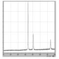
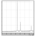
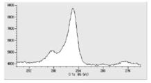
- Tof-SIMS surface analysis was performed to investigate the surface composition of the coated copper particles. From the results of the Tof-SIMS surface analysis, free lauric acid was detected almost quantitatively (shown in FIG. 2A), and a small amount of lauric acid bound to 63 Cu and 65 Cu hydroxides. was also detected (shown in FIG. 2B). Since lauric acid bonded to 63 Cu and 65 Cu was not detected, it was found that what was present on the surface of the coated copper particles was lauric acid coated mostly by physical adsorption.
- TG-DTA analysis was performed (FIG. 3). From the results of TG-DTA analysis, it can be seen that the loss on heating is 1.09% by mass, and that almost all of the product is desorbed near the boiling point of lauric acid. This result also suggests that lauric acid is physically adsorbed, and it is assumed that the coated copper particles can exhibit low-temperature sinterability.
- the coating density of the aliphatic carboxylic acid coating the surface of the copper particles was calculated by the following method. If the total amount of the heat loss component is assumed to be lauric acid according to the analysis result of Tof-SIMS, the number of lauric acids contained in the coated copper particles is expressed by formula (3).
- [laurate number] M acid / (M W / N A) ⁇ (3)
- M acid is heated loss measured mass values (g)
- M W is the molecular lauric acid weight (g / mol)
- N A is the Avogadro constant (6.02 ⁇ 10 23 lines / mol).
- the number of particles in 1 g of copper particles is expressed by the following equation (4).
- Number of particles in 1g] M Cu / [( 4 ⁇ r 3/3) ⁇ d ⁇ 10 -21] ⁇ (4)
- M Cu is a calculated mass value (g) obtained from the measured heat loss
- r is the radius (nm) of the primary particle diameter calculated by SEM observation
- the particle surface area in 1 g of copper particles is represented by the formula (5) using the formula (4).
- the coating density of lauric acid in the coated copper particles was 4.23 particles / nm 2 .
- the minimum area is calculated from the van der waals radius of the stearic acid molecule from “Chemistry and Education, Vol. 40, No. 2, (1992) Obtaining the cross-sectional area of the stearic acid molecule—experimental values and calculated values—”.
- the theoretical value of the saturated covered area converted from is about 5.00 lines / nm 2 . From this theoretical value, it is presumed that the coated copper particles of this embodiment have lauric acid localized on the particle surface at a relatively high density. This dense coating effect can be considered as a reason why the lauric acid coating is excellent in oxidation resistance in spite of physical adsorption that is weaker than chemical adsorption.
- Example 1 the reaction mechanism of the present invention was estimated by component analysis of the gas discharged during the reaction and the evaporated distillate, taking Example 1 as an example.
- ⁇ Gas component analysis> Method Gas chromatograph Measuring instrument: GL Science GL320 Detector: Thermal conductivity detector (TCD) Column: Stainless steel column ⁇ 3mm ⁇ 2m Column packing (hydrogen): Molecular Sieve 5A Column packing (carbon dioxide): Active Carbon Carrier gas (hydrogen): N 2 20 mL / min Carrier gas (carbon dioxide): He 50mL / min Measurement temperature: 43-50 ° C Current value: 70 to 120 mA
- the exhaust gas component is carbon dioxide gas
- the reaction temperature is around 120 ° C. (FIG. 4). Therefore, it is considered that the reaction mechanism proceeds through the following reaction equation 1 and the reaction mechanism of reaction equation 2. That is, first, one molecule of lauric acid causes an equilibrium exchange reaction with one molecule of formic acid of a copper formate amino alcohol complex.
- exhaust gas components are hydrogen gas and carbon dioxide gas, and it is considered that the following reaction mechanism proceeds from the component ratio.
- Scheme 4 (HCOO ⁇ ) (HCOO ⁇ ) Cu 2+. (H 2 NC 3 H 6 OH) 2 ⁇ Cu + 2H 2 NC 3 H 6 OH + H 2 + 2CO 2 It is considered that not only reaction formula 1 but also reaction formula 4 proceeds simultaneously as lauric acid is consumed as a covering material of the reduced copper particle growth mechanism rather than the equilibrium exchange reaction of complex formation with copper formate.
- reaction Formula 7 CuO + 2HCOOH ⁇ (HCOO ⁇ ) (HCOO ⁇ ) Cu 2+ + H 2 O
- the regenerated copper formate regenerates according to reaction formula 2 via reaction formula 1. It is thought that water molecules were generated by these side reactions and were discharged as an evaporating fraction. Since this side reaction is a reaction that can occur if formic acid is present in the reaction system, even if copper oxide is unexpectedly formed, the coated copper having no oxide film due to the reduction reaction mechanism of reaction formula 6 and reaction formula 7. It is presumed that particles can be synthesized. In order to verify whether this reduction reaction mechanism can occur in the manufacturing method of the present embodiment, the reaction was intentionally performed by adding copper oxide to the reaction system. The result will be described in Reference Example 2.
- the mixture was heated and stirred at 200 rpm until the liquid temperature reached 50 ° C. Thereto, 21.0 g (3.50 equivalent / copper formate anhydride) of 3-amino-1-propanol (manufactured by Tokyo Chemical Industry Co., Ltd.) was slowly added dropwise. After completion of the dropwise addition, the mixture was heated and stirred at 340 rpm until the liquid temperature became around 120 ° C. As the liquid temperature rises, the reaction solution starts to change from dark blue to brown, and carbon dioxide gas bubbling occurs. The oil bath temperature control was stopped at the point where the bubbling of the carbon dioxide gas stopped, and the temperature was cooled to room temperature.
- This precipitate was transferred to a 100 mL eggplant flask while being washed with 20.0 g of methanol (manufactured by Kanto Chemical Co., Inc.). The mixture was allowed to stand for 30 minutes or more, the supernatant was decanted, and the resulting precipitate was placed on a rotary evaporator and vacuum dried at 40 ° C. and 1 kPa or less. After completion of the vacuum drying, the solution was cooled to room temperature and released under reduced pressure while being purged with nitrogen to obtain 6.5 g of brown copper powder.
- a copper formate amino alcohol complex containing an aliphatic carboxylic acid is formed as in this embodiment (Scheme 8).
- the thermal decomposition temperature of such a copper formate complex is low, aliphatic carboxylic acid and copper formate amino alcohol complex It is described that formic acid eliminated in the exchange reaction is discharged out of the system.
- the reaction conditions are at a low temperature, it is considered that the reduction reaction with formic acid present in the reaction system does not proceed.
- reaction mechanism of the present embodiment has a reaction mechanism for reducing the by-produced copper oxide by the reaction formula 6 and the reaction formula 7 as well as the production of reduced copper by the thermal decomposition reaction of the copper formate complex.
- the coated copper particles to be synthesized are less prone to oxidation.
- the production method of this embodiment does not require strict production control of water and oxygen, which are cited as causes of metal copper oxidation, and is a production method suitable for simpler synthesis.
- the difference between the SP value of the amino alcohol constituting the copper formate amino alcohol complex and the reaction solvent, or the SP value of the mixed solvent of the main solvent and the auxiliary solvent, that is, the ⁇ SP value is 4.2 or more. If it is large, individual coated copper particles can be produced, but if it is 4.2 or less, it does not become individual coated copper particles but forms an aggregate, and as a method for producing coated copper particles, It turns out that it is not suitable. Further, the ratio of the size of the crystal particles in the primary particles, which is defined as crystallinity, is 0.25 or more, and in most cases, about 0.50, and the coated copper particles are composed of one large crystallite. The appearance is shown.
- Example X-ray powder analysis and SEM observation were performed on the coated copper particles obtained in Examples 5 to 8 and Comparative Examples 6 to 7. The results are shown in Table 3.
- the heating rate during the reaction is constant, the reduction reaction rate will be the same, and the amount of metal nuclei generated will be the same. Therefore, it controls the size and stability of the micro-reaction field similar to water-in-oil emulsion. It can be seen that there is a difference in particle size and particle size distribution depending on the factors to be performed. In the direction of stabilizing the micro reaction field, the particle diameter and the fluctuation rate tend to be small, and this tendency becomes larger as the carbon chain of the aliphatic carboxylic acid becomes longer (comparison of Example 1, Example 5 and Example 9).
- Example 1 the number of moles of aliphatic carboxylic acid with respect to copper atoms tends to stabilize, but when the reaction viscosity increases, the particle size increases even if the rate of change is small (Examples 1, 6 and 7). comparison). If the ratio of the main solvent to the auxiliary solvent in the reaction solvent is changed and the average SP value varies from 8.21 to 8.90, even if ⁇ SP with amino alcohol is ensured, the properties of the obtained coated copper particles are improved. It was also confirmed that there was no significant difference (comparison of Example 1 and Example 8).
- JP 2013-047365 A which is similar in that the coated copper particle of the present embodiment and the coating material are aliphatic carboxylic acids, Tried to manufacture.
- These methods are methods for producing coated copper particles using a copper atom source as a reservoir which is a hardly soluble solid.
- a raw material cuprous (I) having a particle size as small as 2 to 4 ⁇ m was used, but unreacted substances remained for a predetermined time. Although the reaction time was quantitatively converted to reduced copper, the average particle size was increased. In addition, the particle size distribution was as large as the fluctuation rates of 0.38 and 0.29.
- Example 2 Characteristics of the fired film by the coated copper particle paste
- the coated copper particles produced under the conditions of Example 1 were dispersed with a solvent to prepare a copper paste composition, and 300 ° C and 350 ° C under a nitrogen atmosphere.
- a copper film (copper paste sintered layer) was prepared by firing for 1 hour, and the electric resistance of the film was measured.
- a copper paste composition having a metal content of 33% by volume was prepared by dispersing and kneading the coated copper particles and the solvent with a mortar so as to have the following composition to form a paste.
- 26A and 26B show SEM observation images of the produced coated copper particles and the fired copper film, and Table 4 shows the measurement results of electric resistance.
- Test Example 4 Characteristics of fired film by mixed paste of coated copper particles and copper powder
- the coated copper particles produced in Example 1 were added as a sintering agent for a commercially available copper powder to prepare a copper paste composition.
- a copper film was prepared by baking at 300 ° C. and 350 ° C. for 1 hour in a nitrogen atmosphere, and the electric resistance of the film was measured.
- Each material was dispersed and kneaded with a three roll mill so as to have the following composition to prepare a copper paste composition having a metal content of 60% by volume.
- Copper paste composition C Coated copper particles of Example 1 100 parts by weight Wet copper powder 2.0 ⁇ m (Mitsui Metals: 1200N) 100 parts by weight Wet copper powder 0.8 ⁇ m (Mitsui Metals: 1050Y) 25 parts by weight Polyacrylic acid dispersant 0. 5 parts by weight Kyowanol M (NH Neochem) 15 parts by weight
- An about 10 ⁇ m wet coating was applied to a 40 ⁇ m thick polyimide film laminated with a 12 ⁇ m copper foil on the back side, and dried and fired in a nitrogen atmosphere to prepare a sample for evaluation.
- the average film thickness of the copper after firing was measured by cross-sectional observation with SEM.
- the film thickness of the copper paste sintered layer was 4.2 ⁇ m.
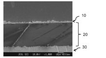
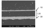
- An SEM cross-sectional observation image of the evaluation sample used for the measurement is shown in FIG. In FIG. 27, on the surface opposite to the copper foil layer 30 of the polyimide film having a 12 ⁇ m thick copper foil layer 30 on one surface of the 40 ⁇ m thick polyimide film layer 20, a fired product of the copper paste composition A certain copper paste sintered layer 10 is formed.
- the copper paste composition B was coated copper particles coated with the same aliphatic carboxylic acid, and showed a value of 22 ⁇ ⁇ cm, which is one digit higher than the volume resistivity value of the copper bulk.
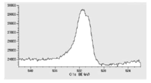
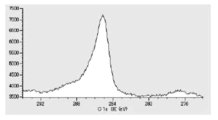
- the surface composition structure of the sintered copper film produced with the copper paste compositions A and B was subjected to composition analysis by XPS, and the mechanism by which the difference in electrical characteristics occurred was considered.
- the data obtained by the narrow scan in FIGS. 28 and 29 show composition information on the outermost surface of the sintered copper coatings of the copper paste compositions A and B. It can be seen that the outermost surface of the sintered copper film of the copper paste composition B has a higher ratio of reduced copper and a lower ratio of the copper oxide component and the organic component than that of the copper paste composition A.
- the outermost surface of the sintered copper film made of the copper paste composition A is coated with an aliphatic carboxylic acid presumed to be lauric acid, and the amount of organic components increases accordingly. However, although there is an oxide component, a considerable amount of reduced copper is exposed, and it is determined that the contact resistance is not impaired.
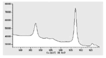
- etching was performed with argon ions, and the surface composition in the region of several nm from the outermost surface was clarified by XPS DepthProfile analysis.
- the copper paste composition B is expected to have a lower sintered density because the carbon content does not decrease even in a region deeper than several nm compared to A.
- the mechanism for expressing the low-temperature sinterability of the coated copper particles is not to remove the coating material of the coated copper particles at a low temperature, but to prevent contact between the copper particles, necking and mutual diffusion of copper atoms. It has been found that it is important to be removed moderately.
- the sintered copper film obtained from the coated copper particles of the present invention the aliphatic carboxylic acid in the coating material existing between the particles is efficiently removed while the particles contact, necking, and interdiffusion of copper atoms.
- characteristics close to the resistance value of the copper bulk can be achieved.
- the outermost surface of the sintered copper film is covered with the aliphatic carboxylic acid of the coating material and can be expected as a barrier layer against oxygen.
- the method for producing coated copper particles according to the present invention comprises coated copper particles having excellent oxidation resistance in which the particle diameter is controlled by a unique micro reaction field and the particle surface is covered with a high-density coating layer of aliphatic carboxylic acid. Can be manufactured.
- the obtained coated copper particles are almost composed of reduced copper, and it is considered that the aliphatic carboxylic acid as the coating material is bonded by physical adsorption. Therefore, in order to express the sintering ability by being desorbed near the boiling point of the coating material, for example, a copper sintered film having a volume resistivity close to copper bulk at a relatively low temperature of 300 ° C. or less at normal pressure. Obtainable.
- the coated copper particles can be made into a paste with a solvent and the like, and a wiring pattern can be formed by means such as screen printing, and the firing atmosphere of the formed wiring pattern only needs to be in a low oxygen state.
- a highly versatile production process that can be used can be configured.
Abstract
Description
また、特開2008-013466号公報又は特開2008-031104号公報に記載の技術では、ギ酸銅錯体を構成する脂肪族アミンは、金属微粒子の分散保護剤の役割を同時に果たす為、粒子成長が起こりにくく、20nmからサブミクロンの粒子径を有する銅粒子を製造することは困難である。
(1) ギ酸銅、アミノアルコール、炭素数が5以上の脂肪族基を有する脂肪族カルボン及び溶媒を含む反応液を得ることと、反応液中に生成する錯化合物を熱分解処理して金属銅を生成することと、を含み、アミノアルコールと溶媒とのSP値の差であるΔSP値が4.2以上である、脂肪族カルボン酸で表面が被覆された被覆銅粒子の製造方法である。
(2) アミノアルコールのSP値が11.0以上である、(1)に記載の被覆銅粒子の製造方法である。
(3) 熱分解処理の温度が100℃~130℃である、(1)又は(2)に記載の被覆銅粒子の製造方法である。
(4) 溶媒が、水と共沸混合物を形成し得る有機溶剤を含み、熱分解処理が生成する水の少なくとも一部を共沸により除去することを含む、(1)~(3)のいずれかに記載の被覆銅粒子の製造方法である。
(5) 脂肪族カルボン酸の脂肪族基部分の炭素数が5~17である、(1)~(4)のいずれかに記載の被覆銅粒子の製造方法である。
(6) 反応液中の銅イオン濃度が1.0~2.5モル/リットルである、(1)~(5)のいずれかに記載の被覆銅粒子の製造方法である。
(7) (1)~(6)のいずれかに記載の被覆銅粒子の製造方法で得られ、SEM観察による平均一次粒子径DSEMが0.02~0.2μmであり、粒度分布の変動係数(標準偏差SD/平均一次粒子径DSEM)の値が0.1~0.5である被覆銅粒子である。
(8) (1)~(6)のいずれかに記載の被覆銅粒子の製造方法で得られ、粉体X線解析から求まる結晶粒子径DXRDのSEM観察による平均一次粒子径DSEMに対する比DXRD/DSEMが0.25~1.00である被覆銅粒子である。
(9) (1)~(6)のいずれかに記載の被覆銅粒子の製造方法で得られる被覆銅粒子と媒体とを含むスクリーン印刷用の導電性組成物である。
(10) (1)~(6)のいずれかに記載の被覆銅粒子の製造方法で得られる被覆銅粒子と媒体とを含むインクジェット印刷用の導電性組成物である。
(11) 基材と、基材上に配置された(9)又は(10)に記載の導電性組成物の熱処理物である配線パターンとを備える回路形成物である。
本実施形態の被覆銅粒子の製造方法は、ギ酸銅、アミノアルコール、炭素数が5以上の脂肪族基を有する脂肪族カルボン及び溶媒を含む反応液を得ることと、反応液中に生成する錯化合物を熱分解処理して金属銅を生成することと、を含み、アミノアルコールと溶媒とのSP値の差であるΔSP値が4.2以上である、脂肪族カルボン酸で表面が被覆された被覆銅粒子の製造方法である。
更に液相中に脂肪族カルボン酸が存在することで、物理吸着により脂肪族カルボン酸が生成した還元銅粒子を高密度に被覆する。こうして製造される被覆銅粒子は、酸化膜がほとんどない還元銅粒子で構成され、その表面を物理吸着により脂肪族カルボン酸が被覆しているため、耐酸化性と焼結性のバランスに優れていると考えられる。これにより、被覆銅粒子の焼成工程において、銅粒子を被覆している有機保護剤である脂肪族カルボン酸が400℃以下の温度で除去される。そのため水素ガスなどの還元雰囲気を用いるまでもなく、窒素置換等の手段で達成し得る低酸素雰囲気において、被覆銅粒子同士の焼結を行うことができる。したがって、焼結に還元性雰囲気を必要とする従来の銅粒子では、適用が困難であった部位、例えば、水素脆化又は水素との反応による変質が問題となる部位にも効果的に使用することができる。また、窒素置換リフロー炉などの既存の設備を利用して焼結させることができるため、経済性の点においても優れる。
ギ酸銅は2価の銅イオンと銅イオン1モルに対して2モルのギ酸イオンとから構成される。ギ酸銅は無水物であっても、水和物であってもよい。また、ギ酸銅は市販品を用いてもよく、新たに調製したものを用いてもよい。
ギ酸銅を熱分解して還元銅の微粒子を得る方法は、例えば、特公昭61-19682号公報などに開示されている。ギ酸は、通常のカルボン酸と異なり、還元性を有するので、ギ酸銅を熱分解すると2価の銅イオンを還元することができる。例えば、無水ギ酸銅は、不活性ガス中で加熱すると210℃~250℃で熱分解して金属銅を生成することが知られている。
アミノアルコールは、少なくとも1つのアミノ基を有するアルコール化合物であって、ギ酸銅と錯化合物を形成可能な化合物であれば特に制限されない。反応液中にアミノアルコールが存在することで、ギ酸銅から錯化合物が生成し、溶媒に可溶化することができる。
アミノアルコールは、モノアミノモノアルコール化合物であることが好ましく、アミノ基が無置換のモノアミノモノアルコール化合物であることがより好ましい。またアミノアルコールは、単座配位性のモノアミノモノアルコール化合物であることもまた好ましい。
分子間結合エネルギーE1は蒸発潜熱から気体エネルギーを差し引いた値である。蒸発潜熱Hbは、試料の沸点Tbとして下式で与えられる。
Hb = 21×(273+Tb)
このHb値から25℃におけるモル蒸発潜熱H25が下式で求められる。
H25 = Hb×[1+0.175×(Tb-25)/100]
モル蒸発潜熱H25から分子間結合エネルギーEが下式より求められる。
E = H25-596
分子間結合エネルギーEから試料1mLあたりの分子間結合エネルギーE1が下式により求められる。
E1 = E×D/Mw
ここで、Dは試料の密度、Mwは試料の分子量であり、E1よりSP値が下式により求められる。
SP =(E1)1/2
なお、OH基を含む溶剤は、OH基1基につき+1の補正が必要である。
〔例えば、三菱石油技資、No.42,p3,p11(1989)参照〕
反応液におけるアミノアルコールの含有量は特に制限されず、目的等に応じて適宜選択することができる。アミノアルコールの含有量は、例えば、反応液中の銅イオンに対して1.5~4.0倍モルの範囲が好ましく、1.5~3.0倍モルの範囲がより好ましい。アミノアルコールの含有量が銅イオンに対して1.5倍モル以上であるとギ酸銅の溶解性が充分に得られ、反応に要する時間を短縮することができる。また4.0倍モル以下であると生成する被覆銅粒子の汚染を抑制することができる。
脂肪族カルボン酸は、脂肪族基の炭素数が5以上の長鎖の脂肪族カルボン酸であれば特に制限されない。脂肪族基は、直鎖状及び分岐鎖状のいずれであってもよく、また飽和脂肪族基及び不飽和脂肪族基のいずれであってもよい。脂肪族基の炭素数は5以上であるが、5以上17以下であることが好ましく、7以上17以下であることがより好ましい。脂肪族基の炭素数が5以上であると、粒度分布の指標となる変動率が小さくなる傾向がある。これは例えば、炭素鎖の長さが会合力を左右するファンデルワールス力の大きさと相関性が高いことで説明できる。すなわち、炭素鎖の長いカルボン酸は、会合力が強く、ミクロ反応場であるWater-in-oil Emulsion類似の相安定化に寄与することで粒子径の揃った銅粒子を効率よく製造できると考えられる。
反応液における脂肪族カルボン酸の含有量は特に制限されず、目的等に応じて適宜選択することができる。脂肪族カルボン酸の含有量は、例えば、反応液中の銅イオンに対して2.5~25モル%の範囲が好ましく、5.0~15モル%の範囲がより好ましい。脂肪族カルボン酸の含有量が銅イオンに対して25モル%以下であると反応系の粘度上昇を抑制できる傾向がある。また脂肪族カルボン酸の含有量が銅イオンに対して2.5モル%以上であると、充分な反応速度が得られ生産性が向上する傾向があり、粒度分布の指標となる変動率が小さくなる傾向がある。
反応液を構成する溶媒は、ギ酸による還元反応を過度に阻害せず、アミノアルコールとのSP値の差であるΔSP値が4.2以上となるように選択される限り特に制限はなく、通常用いられる有機溶剤から適宜選択することができる。
アミノアルコールのSP値と溶媒のSP値との差であるΔSP値が4.2以上であると、形成される被覆銅粒子の粒度分布の幅が狭い、粒子径の揃った被覆銅粒子が得られる。
溶媒のSP値は、ΔSP値が4.2以上となるように選択されるが、溶媒のSP値は、アミノアルコールのSP値よりも小さいことが好ましい。溶媒のSP値は11.0以下であることが好ましく、10.0以下であることがより好ましい。溶媒のSP値の下限は特に制限されず、例えば溶媒のSP値は、7.0以上であることが好ましい。
さらに溶媒は、水と共沸混合物を形成可能な有機溶剤であることもまた好ましい。水と共沸混合物を形成可能であると、熱分解処理によって反応液中に生成した水を容易に反応系から除去することができる。
溶媒は1種単独でも2種以上を組合せて用いてもよい。
補助溶剤の沸点の好ましい態様は、主溶剤と同様である。補助溶剤のSP値は主溶剤をよりも大きいことが好ましく、アミノアルコールと相溶する程度に大きいことがより好ましい。補助溶剤の具体例としては、EO系グリコールエーテル、PO系グリコールエーテル、ジアルキルグリコールエーテルなどのグリコールエーテルを挙げることができる。より具体的には、メチルジグリコール、イソプロピルグリコール、ブチルグリコール等のEO系グリコールエーテル;メチルプロピレンジグリコール、メチルプロピレントリグリコール、プロピルプロピレングリコール、ブチルプロピレングリコール等のPO系グリコールエーテル、ジメチルジグリコール等のジアルキルグリコールエーテルなどを挙げることができ、これらからなる群から選択される少なくとも1種が好ましい。なお、これらの補助溶剤は、いずれも日本乳化剤(株)等より入手可能である。
δ3=〔V1×δ1+V2×δ2〕/(V1+V2)
δ3:混合溶媒の平均SP値、δ1:溶媒1のSP値、V1:溶媒1のモル容積、
δ2:溶媒2のSP値、V2:溶媒2のモル容積
ギ酸銅、アミノアルコール、長鎖脂肪族カルボン及び溶媒を含む反応液からは、ギ酸銅に由来する錯化合物が生成する。錯化合物の構造は特に限定されず、1種のみからなっていてもよく、2種以上を含んでいてもよい。また、錯化合物は、熱分解処理の進行に伴い、その構成が変化してもよい。すなわち、熱分解処理の初期において主として存在する錯化合物と、熱分解処理の後期において主として存在する錯化合物は互いに構成が異なるものであってもよい。
反応液中に生成する錯化合物として具体的には、1個の銅イオンに2分子のギ酸イオンと2分子のアミノアルコールとが配位した錯化合物、1個の銅イオンに1分子のギ酸イオンと1分子の脂肪族カルボン酸と2分子のアミノアルコールとが配位した錯化合物等が挙げられる。
水の除去方法は特に制限されず、通常用いられる水分除去方法から適宜選択することができる。例えば、溶媒として水と共沸混合物を形成し得る有機溶剤を用いて、共沸により生成する水を除去することが好ましい。
すなわち、ギ酸銅を反応溶媒に可溶化するための錯化剤としてのアミノアルコールと溶媒とのSP値の差であるΔSP値を4.2以上とすることで、ギ酸銅アミノアルコール錯体又はギ酸の1分子が脂肪族カルボン酸で置換されたギ酸銅アミノアルコール錯体の状態では溶解しているが、錯体が熱分解されて錯化剤であるアミノアルコールが遊離すると、遊離したアミノアルコールは溶媒とは相溶できず、2相を形成し始めるようになる。遊離したアミノアルコールは、ギ酸銅やギ酸銅アミノアルコール錯体と親和性が高いため、ギ酸銅の新たなる錯化剤又は溶剤として振る舞い、極性の高い内核(液滴)を形成し、外側を極性の低い溶媒が取り囲むWater in oil Emulsion類似の2相構造を取るようになり、これがマイクロ反応場として機能すると推定される。
さらに反応系中の水も脂肪族カルボン酸の置換で脱離したギ酸もこのマイクロ反応場に存在している。マイクロ反応場の中に金属核、その成長粒子及び金属核の発生源であるギ酸銅アミノアルコール錯体、ギ酸の1分子が脂肪族カルボン酸で置換されたギ酸銅アミノアルコール錯体、水並びにギ酸が隔離されて反応が進行する。脂肪族カルボン酸が金属銅成長粒子の被覆材として固定化され、減少するにつれて反応初期ではギ酸銅錯体の熱分解機構が後述する反応式1~3で進行していたものが、次第に反応式4の機構で進行するようになり、発生ガス成分が変化してくる。マイクロ反応場では、反応式5に示す水によるギ酸銅アミノアルコール錯体の加水分解でCuOが生成するが、反応式6又は反応式7を経由して再び還元されるため、亜酸化銅や酸化銅を含まない還元銅粒子が製造可能となっている。また、マイクロ反応場に含まれる銅原子数が限定されているため、銅粒子の粒子径は一定に制御される。
そして、マイクロ反応場に、表面に酸化銅が形成されていない銅粒子が生成するため、マイクロ反応場に存在する脂肪族カルボン酸が物理吸着しやすくなり、粒子径が揃い、耐酸化性と焼結性に優れる被覆銅粒子が効率的に得られると考えることができる。
本実施形態の被覆銅粒子は、既述の被覆銅粒子の製造方法で製造され、SEM観察による平均一次粒子径DSEMが0.02~0.2μmであり、粒度分布の変動係数(標準偏差SD/平均一次粒子径DSEM)の値が0.1~0.5である。
既述の被覆銅粒子の製造方法で製造されていることで、粒度分布の変動係数が小さく、粒子径の揃った状態となる。被覆銅粒子の粒度分布の変動係数が小さいことで、分散性に優れ、高濃度の分散物を容易に作製できるという効果が得られる。
本実施形態の導電性組成物は、既述の被覆銅粒子の製造方法で得られる被覆銅粒子の少なくとも1種と、媒体とを含む。導電性組成物は、配線パターン形成に好適に用いることができ、低温で、導電性に優れる配線パターンを容易に形成することができる。
すなわち、本実施形態は、前記被覆銅粒子の導電性組成物としての使用を包含する。
例えば、導電性組成物がスクリーン印刷用である場合、媒体としては、炭化水素溶剤、高級アルコール溶剤、セロソルブ、セロソルブアセテート溶剤等を挙げることができる。
また、スクリーン印刷用の導電性組成物の固形分濃度は、例えば、40~95質量%とすることができる。ここで導電性組成物の固形分とは不揮発性成分の総量を意味する。
インクジェット印刷用の導電性組成物の固形分濃度は、例えば、40~90質量%とすることができる。
本実施形態の回路形成物は、基材と、基材上に配置される上記導電性組成物の熱処理物である配線パターンとを備える。配線パターンが上記導電性組成物から形成されることで、配線パターンの導電性に優れる。また低温で配線パターンを形成することができるため、基材の選択肢の自由度が大きい。
回路形成物は、例えば、基材を準備する工程と、基材上に導電性組成物を付与する工程と、導電性組成物を熱処理する工程とを含む製造方法で製造できる。すなわち、本実施形態は、前記導電性組成物を用いる回路形成物の製造方法をも包含する。
熱処理の時間は、例えば1~120分間とすることができ、5~60分間であることが好ましい。
熱処理の雰囲気は、低酸素雰囲気であることが好ましい。低酸素雰囲気としては、窒素雰囲気、アルゴン雰囲気等を挙げることができる。また酸素濃度が1,000ppm以下であることが好ましい。
<平均一次粒子径及び変動率の計算>
測定装置:日本電子製FE-EPMA JXA-8510F
平均一次粒子径:サンプル20点の平均値
変動率:サンプル20点の標準偏差/平均値で計算される値
測定装置:日本電子製FE-EPMA JXA-8510F
測定条件:加速電圧 6KV又は15KV
観察倍率 ×10,000~×75,000
測定器:島津製 XRD-6100
測定条件:ターゲット Cu
管電圧 40KV、管電流 30.0mA
測定器;ULVAC-PHI製 PHI TRIFT IV型
測定条件:1次イオン種 Au、加速電圧 30KV
測定装置:リガク製 TG8120
昇温速度:10℃/min
測定温度範囲:25℃~600℃
測定雰囲気:窒素 100ml/min
測定装置:堀場製作所製 LA-960
測定溶媒:キョウワノールM
分散剤:ポリアクリル酸系分散剤
分散方法:超音波5分
測定装置:共和理研製 K-705RS
測定方法:四端子測定法
測定点数:n=5の平均値
導電膜厚:SEM断面観察により決定
測定装置:JEOL製JPS-9010MX
高速エッチングイオン銃:XP-HSIG3
DepthProfile分析条件
イオンビーム径:φ15mm、Arイオン加速電圧:500V(電流:8.6mA)
SiOエッチング速度で20~25nm/min相当
(Data_0からData_6は、下から上へ)
Data_0:エッチングなし
Data_1:実行エッチング時間-0.9秒(累計:0.9秒)
Data_2:実行エッチング時間-3.0秒(累計:3.9秒)
Data_3:実行エッチング時間-3.0秒(累計:6.9秒)
Data_4:実行エッチング時間-3.0秒(累計:9.9秒)
Data_5:実行エッチング時間-3.0秒(累計:12.9秒)
Data_6:実行エッチング時間-3.0秒(累計:15.9秒)
本実施例で用いたギ酸銅、ギ酸銅無水物の製造事例を以下に示すが、ギ酸銅の製造方法は、複数の方法がすでに公知であり、他の方法で製造されたギ酸銅を使用してもよい。
塊があると未反応で残存しやすいため、28メッシュ程度の篩い処理を行った。
[合成手順]
5リットル4ツ口フラスコにギ酸0.96kg、イオン交換水1.44kgを加えて均一に攪拌しながら、塩基性炭酸銅を少しずつ加えた。炭酸ガスの発生に注意しながら全量を加えた。投入し終えたら、温度を60℃まで昇温させて0.5時間反応を継続した。炭酸ガスの流出(ドレインを水トラップに導き、確認する)がほとんどなくなったのを確認して、この時点では、ギ酸銅及び塩基性炭酸銅が一部未溶解で残っていた。イオン交換水1.60Kgを追加して60℃で1.0時間反応を継続した。反応液が濃青色透明液となったことを確認して反応を終了し、エバポレーターで減圧濃縮して、水を1.5リットル留去した。この時点ですでに結晶が析出して、スラリー状になっていた。
室温まで冷却して反応物をろ過して、アセトン1リットルで洗浄した。得られた結晶は、緑青色を示した。
次いで乾燥脱水を以下のようにして行った。乾燥温度は、真空0.5KPa(最終)にて80℃以下(粉体の温度)で実施した。乾燥脱水によりライトブルー色結晶となった。
ギ酸銅の熱分解温度:214.9℃(窒素中)、大気中では200℃付近
[品質確認]
TG-DTA測定で含有Cu%が理論値に近似していることを確認した。
ギ酸銅無水物の式量:153.84
含有Cu%=41.3%、減量%=58.5%程度
攪拌機、温度計、還流冷却管、75mLディーンスターク管、窒素導入管を備えた3000mLガラス製四ツ口フラスコをオイルバスに設置した。そこへ、ギ酸銅無水物484g(3.1モル)と、ラウリン酸(関東化学社製)68.1g(0.11当量/ギ酸銅無水物)と、反応溶媒としてトリプロピレングリコールモノメチルエーテル(東京化成社製)150g(0.23当量/ギ酸銅無水物)及びスワクリーン150(ゴードー社製)562g(1.42当量/ギ酸銅無水物)とを添加し、200rpmで攪拌しながら混合した。窒素雰囲気下、液温度が50℃になるまで200rpmで加温攪拌した。そこへ、3-アミノ-1-プロパノール(東京化成社製)712g(3.00当量/ギ酸銅無水物)ゆっくり滴下した。滴下終了後、液温度が120℃付近になるまで340rpmで加温攪拌した。ディーンスターク管によりトラップされた水層は適時除去し、反応系内に還流されないようにした。液温度が上昇するにつれて、反応溶液は濃青色から茶褐色に変化し始め、炭酸ガスの発泡が生じた。炭酸ガスの発泡が収まったところを反応終点として、オイルバス温調を停止し、室温まで冷却した。
室温まで冷却後、メタノール(関東化学社製)550gを添加し、混合させた。この混合溶液を30分以上静置して、上澄みをデカンテーションし、沈殿物を得た。この沈殿物にメタノール(関東化学社製)550g、アセトン(関東化学社製)300gを添加し、混合した。この混合溶液を30分以上静置して、上澄みをデカンテーションし、沈殿物を得て、この操作を更にもう一回繰り返した。この沈殿物をメタノール(関東化学社製)550gを用いて共洗いしながら500mLナスフラスコに移した。30分以上静置して、上澄みをデカンテーションし、得られた沈殿物を回転式エバポレーターに設置し、40℃、1kPa以下で真空乾燥した。真空乾燥終了後、室温まで冷却し窒素置換しながら減圧解除し、194gの茶褐色の被覆銅粒子を得た。
得られた被覆銅粒子のSEM観察画像を図7に示す。また拡大SEM観察画像を図20Aに、粒度分布を図20Bに示す。
3-アミノ-1-プロパノールをDL-1-アミノ-2-プロパノールに変えた以外は、実施例1と同様に被覆銅粒子を合成した。
得られた被覆銅粒子のSEM観察画像を図8に示す。
3-アミノ-1-プロパノールを5-アミノ-1-ペンタノール、反応溶媒をn-オクタンに変えた以外は、実施例1と同様に被覆銅粒子を合成した。
3-アミノ-1-プロパノールをDL-1-アミノ-2-プロパノール、反応溶媒をn-オクタンに変えた以外は、実施例1と同様に被覆銅粒子を合成した。
得られた被覆銅粒子のSEM観察画像を図9に示す。
3-アミノ-1-プロパノールを1-ヘキシルアミンに変えた以外は、実施例1と同様に被覆銅粒子を合成した。
得られた被覆銅粒子のSEM観察画像を図10に示す。
3-アミノ-1-プロパノールを2-ジエチルアミノエタノールに変えた以外は、実施例1と同様に被覆銅粒子を合成した。
得られた被覆銅粒子のSEM観察画像を図11に示す。
3-アミノ-1-プロパノールを2-ジメチルアミノエタノールに変えた以外は、実施例1と同様に被覆銅粒子を合成した。
得られた被覆銅粒子のSEM観察画像を図12に示す。
3-アミノ-1-プロパノールを5-アミノ-1-ペンタノールに変えた以外は、実施例1と同様に被覆銅粒子を合成した。
得られた被覆銅粒子のSEM観察画像を図13に示す。
反応溶媒をn-オクタノールに変えた以外は、実施例1と同様に被覆銅粒子を合成した。
得られた被覆銅粒子のSEM観察画像を図14に示す。
(実施例5)
ラウリン酸をオレイン酸68.16g、溶媒は補助溶媒を使用せず、スワクリーン#150を712gに変えた以外は、実施例1と同様に被覆銅粒子を合成した。
得られた被覆銅粒子のSEM観察画像を図15に示す。
ラウリン酸48gを16gに変えた以外は、実施例1と同様に被覆銅粒子を合成した。
得られた被覆銅粒子のSEM観察画像を図16A及び図16Bに示す。
ラウリン酸48gを144gに変えた以外は、実施例1と同様に被覆銅粒子を合成した。
得られた被覆銅粒子のSEM観察画像を図17A及び図17Bに示す。
反応溶媒としてスワクリーン#150を150g、メチルプロピレントリグリコールを562gに変えた以外は、実施例1と同様に被覆銅粒子を合成した。
得られた被覆銅粒子のSEM観察画像を図18A及び図18Bに示す。
ラウリン酸をオクタン酸に変えた以外は、実施例1と同様に被覆銅粒子を合成した。
得られた被覆銅粒子のSEM観察画像を図19A及び図19Bに示す。
特開2013-047365号公報の実施例1に記載の方法に準じて、被覆銅粒子を合成した。具体的には以下のように被覆材として酢酸を用いて、被覆銅粒子を合成した。
銅化合物として亜酸化銅(I)(古河ケミカルズ社製;粒子径:2~4μ)を14.3g(0.1モル)、被覆材として酢酸3.0g(50mmol)、還元剤としてヒドラジン・一水和物(和光純薬工業製)5.0g(0.1モル)、溶媒としてイソプロパノールを100ml混合し、300mlの4ツ口フラスコに加えた。フラスコには、冷却器、温度計、窒素導入管及び攪拌装置を取り付けた。窒素を200ml/minを通気しながら、攪拌しつつ70℃まで昇温させ、1時間加熱・攪拌を継続して亜酸化銅(I)を還元させ、被覆銅粒子分散液を得た。
被覆銅粒子分散液を桐山濾紙No.5Bで減圧濾過して、粉体を濾別した。濾別した粉体をメタノール(関東化学工業製)で3回洗浄して40℃、1kPa以下で減圧乾燥させ、室温まで冷却後に窒素置換をして取り出し、12gの茶褐色粉体を得た。
粉体のXRDを測定したところ(図21に示す)、原料に由来すると思われる亜酸化銅(I)が若干検出された。
得られた被覆銅粒子のSEM観察画像を図23Aに示す。
比較例6をスケールアップし、反応時間を2倍にして被覆銅粒子を合成した。銅化合物として亜酸化銅(I)(古河ケミカルズ社製)を71.5g(0.5モル)、被覆材として酢酸15.0g(250mmol)、還元剤としてヒドラジン・一水和物(和光純薬工業製〕25.0g(0.5モル)、溶媒としてイソプロパノールを500ml混合し、1,000mlの4ツ口フラスコに加えた。フラスコには、冷却器、温度計、窒素導入管及び攪拌装置を取り付けた。窒素を200ml/minを通気しながら、攪拌しつつ70℃まで昇温させ、2時間加熱・攪拌を継続して亜酸化銅(I)を還元させ、被覆銅粒子分散液を得た。
被覆銅粒子分散液を桐山濾紙No.5Bで減圧濾過して、粉体を濾別した。濾別した粉体をメタノール(関東化学工業製)で3回洗浄して40℃、1kPa以下で減圧乾燥させ、室温まで冷却後に窒素置換をして取り出し、62gの茶褐色粉体を得た。
粉体のXRDを測定したところ(図22に示す)、原料の亜酸化銅(I)は定量的に還元銅に転化されていた。
得られた被覆銅粒子のSEM観察画像を図26Aに示す。
実施例1で製造された被覆銅粒子を用いて脂肪族カルボン酸で被覆された被覆銅粒子の組成をあきらかにするために、粉体X線分析、SEM観察、Tof-SIMS表面分析及びTG-DTA測定を実施した。
結晶粒子径を粉体X線の回折角度と半値幅からScherrerの式より算出した。Scherrerの式は式(1)で表される。
D=Kλ/(βcosθ)・・・(1)
ここで、Dは結晶粒子径、KはScherrer定数(球体と仮定し、K=1として代入)、λは測定X線の波長(CuKα:1.5418Å)、βは式(2)で表される。
β=b-B・・・(2)
ここで、bはピークの半値幅、Bは装置の補正係数(B=0.114)である。
Tof-SIMSの解析結果にしたがって、加熱減量成分の全量がラウリン酸と仮定すると、被覆銅粒子に含まれるラウリン酸の本数は式(3)で表される。
[ラウリン酸本数] = Macid/(MW/NA) ・・・(3) ここで、Macidは加熱減量測定質量値(g)、MWはラウリン酸分子量(g/mol)、NAはアボガドロ定数(6.02×1023本/mol)である。
SEM観測により算出した一次粒子径はほぼすべて還元銅由来とし、その形状は球体と仮定すると、銅粒子1g中の粒子数は式(4)で表される。
[1g中の粒子数]=MCu/[(4πr3/3)×d×10-21]・・・(4)
ここで、MCuは加熱減量測定値より求められる質量計算値(g)、rはSEM観測により算出した一次粒子径の半径(nm)、dは密度である(銅の密度として代入した;d=8.94)。銅粒子1g中の粒子表面積は式(4)を用いて、式(5)で表される。
[1g中の銅粒子表面積(nm2)]=[1g中の粒子数]×4πr2・・・(5)
ラウリン酸による銅粒子の被覆密度(本/nm2)は、(3)式及び(5)式を用いて、式(6)で表される。
[被覆密度]=[ラウリン酸本数]/[1g中の銅粒子表面積]・・・(6)
『化学と教育 40巻2号(1992年)ステアリン酸分子の断面積を求める-実験値と計算値-』より、ステアリン酸分子のVan der waals半径から最小面積が算出されており、その計算値から換算される飽和被覆面積理論値は約5.00本/nm2である。この理論値から、本実施形態の被覆銅粒子は比較的高密度にラウリン酸が粒子表面に局在化していると推測される。この濃密な被覆効果が、ラウリン酸被覆が化学吸着よりも弱い物理吸着であるにも関わらず、耐酸化性に優れている理由として考えられる。
<ガス成分分析>
方法:ガスクロマトグラフ
測定器:GLサイエンス GL320
検出器:熱伝導度検出器(TCD)
カラム:ステンレスカラム φ3mm×2m
カラム充填剤(水素):Molecular Sieve 5A
カラム充填剤(二酸化炭素):Active Carbon
キャリヤーガス(水素):N2 20mL/min
キャリヤーガス(二酸化炭素):He 50mL/min
測定温度:43~50℃
電流値:70~120mA
方法:赤外分光法
測定器:パーキンエルマー Spectrum One

(反応式1)
(HCOO-)(HCOO-)Cu2+・(H2NC3H6OH)2+C11H23COOH
→(C11H23COO-)(HCOO-)Cu2+・(H2NC3H6OH)2+HCOOH
一般的には、210~250℃付近で熱分解性を示すギ酸銅は、ラウリン酸と3-アミノ-1-プロパノールとによる錯化合物を形成することで熱分解温度が低下すると考えられる。100~130℃付近で錯化合物の熱分解反応により炭酸ガスを放出しながら、2価の銅イオンの還元反応が進行する(反応式2)。錯化合物の分解後に生成する還元銅にはラウリン酸が物理的に吸着されていることが考えられる。
(反応式2)
(C11H23COO-)(HCOO-)Cu2+・(H2NC3H6OH)2
→Cu:C11H23COOH+2H2NC3H6OH+CO2
この還元銅に吸着したラウリン酸は可逆的な平衡をとり(反応式3)、還元銅近傍でギ酸銅アルカノールアミン錯体と反応式1によりラウリン酸平衡交換反応が再び生じ、次々と還元金属核が発生すると考えられる。
(反応式3)
Cu:C11H23COOH
↑↓
Cu+C11H23COOH
(反応式4)。
(HCOO-)(HCOO-)Cu2+・(H2NC3H6OH)2
→Cu+2H2NC3H6OH+H2+2CO2
ギ酸銅との錯化合物形成の平衡交換反応よりも還元銅の粒子成長機構の被覆材としてラウリン酸が消費されるにつれて、反応式1だけではなく反応式4も同時に進行すると考えられる。
特開2011-032558号公報には、残留する水分子によって、ギ酸銅アミノアルコール錯体が加水分解を受け、酸化銅が生成されることが開示されており、本発明に適用すると下記反応により、酸化銅が生成することとなる。
(反応式5)
(HCOO-)(HCOO-)Cu2+・(H2NC3H6OH)2+H2O
→CuO+2H2NC3H6OH+2HCOOH
(反応式6)。
2CuO+2HCOOH→Cu2O+HCOOH+H2O+CO2
→2Cu+2H2O+2CO2
また、反応式7のように酸化銅とギ酸によりギ酸銅が再生し、還元反応が進行することも考えられる。
(反応式7)
CuO+2HCOOH
→(HCOO-)(HCOO-)Cu2++H2O
再生されたギ酸銅は反応式1を経て反応式2に従い、還元反応が進行する。これらの副反応により、水分子が生成し、蒸発留分として排出されたと考える。この副反応は反応系中にギ酸が存在するならば起こり得る反応であるため、予期せず酸化銅が生成しても、反応式6及び反応式7の還元反応機構により酸化膜がない被覆銅粒子の合成が可能となっていると推定される。
この還元反応機構が本実施形態の製造方法で起こりうるか検証するため、意図的に反応系に酸化銅を加えて反応を実施して確認した。その結果を参考例2で説明する。
攪拌機、温度計、還流冷却管、窒素導入管を備えた100mLガラス製四ツ口フラスコをオイルバスに設置した。そこへ、ギ酸銅無水物12.0g(0.08モル)、酸化銅(関東化学社製)2.0g(0.32当量/ギ酸銅無水物)ラウリン酸(関東化学社製試、試薬1級)2.0g(0.12当量/ギ酸銅無水物)、トリプロピレングリコールモノメチルエーテル(東京化成社製)4.4g(0.27当量/ギ酸銅無水物)、スワクリーン150(ゴードー社製)16.6g(1.67当量/ギ酸銅無水物)添加し、200rpmで攪拌しながら混合させた。窒素雰囲気下、液温度が50℃になるまで200rpmで加温攪拌させた。そこへ、3-アミノ-1-プロパノール(東京化成社製)21.0g(3.50当量/ギ酸銅無水物)ゆっくり滴下した。滴下終了後、液温度が120℃付近になるまで340rpmで加温攪拌させた。液温度が上昇するにつれて、反応溶液は濃青色から茶褐色に変化し始め、炭酸ガスの発泡が生じる。炭酸ガスの発泡が収まったところを反応終点として、オイルバス温調を停止し、室温まで冷却した。室温まで冷却後、メタノール(関東化学社製)20.0gを添加し、混合させた。この混合溶液を30分以上静置させて、上澄みをデカンテーションし、沈殿物を得た。この沈殿物にメタノール(関東化学社製)20.0g、アセトン(関東化学社製)10.0gを添加し、混合させた。この混合溶液を30分以上静置させて、上澄みをデカンテーションし、沈殿物を得た。この操作を更にもう一回繰り返した。この沈殿物にメタノール(関東化学社製)20.0gを用いて共洗いしながら100mLナスフラスコに移した。30分以上静置させて、上澄みをデカンテーションし、得られた沈殿物を回転式エバポレーターに設置し、40℃、1kPa以下で真空乾燥した。真空乾燥終了後、室温まで冷却し窒素置換しながら減圧解除し、6.5gの茶褐色銅粉末を得た。
(反応式8)。
(R1COO-)(HCOO-)Cu2+:[(C2H5)2NC2H4OH]2
→Cu:[(C2H5)2NC2H4OH]2+R1COOH+CO2
また、特開2011-032558号公報においては、2座配位性のアミノアルコールに限定されるため、このようなギ酸銅錯体の熱分解温度は低いこと、脂肪族カルボン酸とギ酸銅アミノアルコール錯体の交換反応で脱離するギ酸は、系外に排出されることが記載されている。さらに低温下での反応条件となるため、反応系中に存在するギ酸による還元反応が進行しないと考えられる。
(反応式9)
(HCOO-)(HCOO-)Cu2+・(NH2R2)2
→Cu+2NH2R2+H2+2CO2
これに対して、本実施形態の反応機構においては、ギ酸銅錯体の熱分解反応により還元銅の生成と共に、反応式6及び反応式7により、副生する酸化銅を還元する反応機構も併せ持つため、合成される被覆銅粒子が酸化されにくい製造方法となっている。本実施形態の製造方法は、金属銅の酸化の原因として挙げられる水や酸素の厳密な製造管理は必要なく、より簡便な合成に適した製造方法である。

また、一次粒子に占める結晶粒子の大きさの割合、これを結晶化度と定義すると0.25以上となり、ほとんどの場合は、0.50程度となり、被覆銅粒子を大きな結晶子1個で構成しているようすが示されている。

反応溶媒における主溶剤と補助溶剤の比率を変えて、平均SP値が8.21から8.90と変動してもアミノアルコールとのΔSPが確保されておれば、得られる被覆銅粒子の特性に大きな差異が出ないことも確認された(実施例1及び実施例8の比較)。
実施例1の条件で製造された直後の粉体X線分析結果と25℃で4ヶ月貯蔵した後に同様に測定して酸化の進行の有無を確認した(図1A及び図1B)。4ヶ月後でも酸化成分は検出されず、本実施形態の製造方法で作製された被覆銅粒子は優れた耐酸化性を有することが確認された。
実施例1の条件で製造された被覆銅粒子を溶剤で分散して銅ペースト組成物を作製して、窒素雰囲気下で300℃及び350℃×1時間焼成して銅皮膜(銅ペースト焼結層)を作製してその皮膜の電気抵抗を測定した。被覆銅粒子と溶媒を以下の組成となるように乳鉢を用いて分散混練してペースト化して金属含有量が33体積%の銅ペースト組成物を調合した。
銅ペースト組成物A
実施例1の被覆銅粒子 10質量部
キョウワノールM(NHネオケム製) 2質量部
焼成後の銅の平均膜厚は、SEMによる断面観察で計測した。銅ペースト焼結層の膜厚は、2.4μmであった。
作製された被覆銅粒子と焼成銅皮膜のSEM観察像を図24A及び図24Bに、測定に用いた評価用試料のSEM断面観察像を図25に、測定結果を表4に示す。
図25では、40μm厚のポリイミドフィルム層20の一方の面上に12μm厚の銅箔層30を有するポリイミドフィルムの銅箔層30とは反対側の面上に、銅ペースト組成物の焼成物である銅ペースト焼結層10が形成されている。
比較例7で製造された被覆銅粒子を用い、試験例2と同様にして銅ペースト組成物Bを作製して、窒素雰囲気下で350℃×1時間焼成して銅皮膜を作製してその皮膜の電気抵抗を測定した。
銅ペースト組成物B
比較例7の被覆銅粒子 10質量部
キョウワノールM(NHネオケム製) 2質量部
実施例1で製造された被覆銅粒子を市販の銅粉の焼結剤として添加して銅ペースト組成物を作製して、窒素雰囲気下で300℃及び350℃×1時間焼成して銅皮膜を作製してその皮膜の電気抵抗を測定した。各材料を下記の組成となるように三本ロールミルで分散混練して金属含有量が60体積%の銅ペースト組成物を調合した。
銅ペースト組成物C
実施例1の被覆銅粒子 100質量部
湿式銅粉2.0μm(三井金属製:1200N) 100質量部
湿式銅粉0.8μm(三井金属製:1050Y) 25質量部
ポリアクリル酸系分散剤 0.5質量部
キョーワノールM(NHネオケム製) 15質量部
焼成後の銅の平均膜厚をSEMによる断面観察で計測した。銅ペースト焼結層の膜厚は、4.2μmであった。
測定に用いた評価用試料のSEM断面観察像を図27に、測定結果を表4に示す。
図27では、40μm厚のポリイミドフィルム層20の一方の面上に12μm厚の銅箔層30を有するポリイミドフィルムの銅箔層30とは反対側の面上に、銅ペースト組成物の焼成物である銅ペースト焼結層10が形成されている。

実施例1で製造した被覆銅粒子を用いた銅ペースト組成物Aを試験例2で、市販の銅粉と混ぜて銅ペースト組成物Cを試験例4で、比較として特開2013-047365号公報の実施例1に準じて作製した比較例7で作製した被覆銅粒子を用いた銅ペースト組成物Bを試験例3でそれぞれ、電気特性及びXPSでの表面組成構造を評価した。
その結果、実施例1の被覆銅粒子で調製された銅ペースト組成物A及びCは、4~6μΩ・cmと高い導電性能を示した。また、未処理のポリイミド面に高い密着性を示し、通常の折り曲げ試験では剥離しないことが確認された。銅ペースト組成物Bは同じ脂肪族カルボン酸で被覆された被覆銅粒子であるが、22μΩ・cmと銅バルクの体積固有抵抗値よりも1桁以上高い値を示した。
図28及び図29のNarrowScanで得られたデータには、銅ペースト組成物A及びBの焼結銅皮膜の最表面の組成情報が示されている。銅ペースト組成物Bの焼結銅皮膜の最表面は、銅ペースト組成物Aのそれと比較して、還元銅の割合が高く、酸化銅成分と有機物成分の割合が少ないことが分かる。銅ペースト組成物Aで作成された焼結銅皮膜の最表面は、ラウリン酸と推定される脂肪族カルボン酸で被覆されており、その分、有機物成分が多くなっている。しかし、酸化物成分があるものの還元銅が相当量露出しており、接触抵抗を損なうことはないと判断される。
その結果、銅ペースト組成物A及びBともに最表面から1~2nmよりも深い領域は還元銅で構成されていることがわかった。ただ、銅ペースト組成物Bの方は、Aと比較して数nmより深い領域でも炭素分が減らないことから、焼結密度が低いことが予想される。
また、SEM観察の結果でも焼結密度に明らかな差異があり、これが電気特性の差となって現れたと考えられる。従って、被覆銅粒子の低温焼結性を発現する仕組みは、被覆銅粒子の被覆材が低温で除去されることではなく、銅粒子同士の接触、ネッキング及び銅原子の相互拡散が阻害されないように適度に除去されることが重要なことがわかった。
本発明の被覆銅粒子から得られる焼結銅皮膜においては、粒子間に存在していた被覆材の脂肪族カルボン酸が効率的に除去されつつ、粒子の接触、ネッキング、及び銅原子の相互拡散が達成され、銅バルクの抵抗値に近い特性が達成できている。また、結果的に、焼結銅皮膜の最表面は、被覆材の脂肪族カルボン酸で覆われており、酸素に対するバリア層として期待ができることもわかった。
本明細書に記載された全ての文献、特許出願、及び技術規格は、個々の文献、特許出願、及び技術規格が参照により取り込まれることが具体的かつ個々に記された場合と同程度に、本明細書に参照により取り込まれる。
Claims (11)
- ギ酸銅、アミノアルコール、炭素数が5以上の脂肪族基を有する脂肪酸カルボン酸及び溶媒を含む反応液を得ることと、
反応液中に生成する錯化合物を熱分解処理して金属銅を生成することと、を含み、
アミノアルコールと溶媒とのSP値の差であるΔSP値が4.2以上である、脂肪族カルボン酸で表面が被覆された被覆銅粒子の製造方法。 - アミノアルコールのSP値が11.0以上である、請求項1に記載の被覆銅粒子の製造方法。
- 熱分解処理の温度が100℃~130℃である、請求項1又は2に記載の被覆銅粒子の製造方法。
- 溶媒が、水と共沸混合物を形成し得る有機溶剤を含み、熱分解処理が生成する水を共沸により除去することを含む請求項1~3のいずれか1項に記載の被覆銅粒子の製造方法。
- 脂肪族カルボン酸の脂肪族基の炭素数が5~17である、請求項1~4のいずれか1項に記載の被覆銅粒子の製造方法。
- 反応液中の銅イオン濃度が1.0~2.5モル/リットルである、請求項1~5のいずれか1項に記載の被覆銅粒子の製造方法。
- 請求項1~6のいずれか1項に記載の被覆銅粒子の製造方法で得られ、SEM観察による平均一次粒子径DSEMが0.02~0.2μmであり、粒度分布の変動係数(標準偏差SD/平均一次粒子径DSEM)の値が0.1~0.5である被覆銅粒子。
- 請求項1~6のいずれか1項に記載の被覆銅粒子の製造方法で得られ、粉体X線解析から求まる結晶粒子径DXRDのSEM観察による平均一次粒子径DSEMに対する比DXRD/DSEMが0.25~1.00である被覆銅粒子。
- 請求項1~6のいずれか1項に記載の被覆銅粒子の製造方法で得られる被覆銅粒子と媒体とを含むスクリーン印刷用の導電性組成物。
- 請求項1~6のいずれか1項に記載の被覆銅粒子の製造方法で得られる被覆銅粒子と媒体とを含むインクジェット印刷用の導電性組成物。
- 基材と、基材上に配置された請求項9又は10に記載の導電性組成物の熱処理物である配線パターンとを備える回路形成物。
Priority Applications (6)
| Application Number | Priority Date | Filing Date | Title |
|---|---|---|---|
| CN201580028643.XA CN106457407B (zh) | 2014-05-30 | 2015-05-14 | 被覆铜颗粒的制造方法 |
| US15/307,227 US9744595B2 (en) | 2014-05-30 | 2015-05-14 | Coated copper particles and method for producing the same |
| KR1020167034561A KR101743897B1 (ko) | 2014-05-30 | 2015-05-14 | 피복 구리 입자 및 그 제조 방법 |
| KR1020167027210A KR101709458B1 (ko) | 2014-05-30 | 2015-05-14 | 피복 구리 입자 및 그 제조 방법 |
| EP15799589.5A EP3150306B1 (en) | 2014-05-30 | 2015-05-14 | Coated copper particles and method for manufacturing same |
| US15/685,729 US20180036805A1 (en) | 2014-05-30 | 2017-08-24 | Coated copper particles and method for producing the same |
Applications Claiming Priority (2)
| Application Number | Priority Date | Filing Date | Title |
|---|---|---|---|
| JP2014112794A JP5926322B2 (ja) | 2014-05-30 | 2014-05-30 | 被覆銅粒子及びその製造方法 |
| JP2014-112794 | 2014-05-30 |
Related Child Applications (2)
| Application Number | Title | Priority Date | Filing Date |
|---|---|---|---|
| US15/307,227 A-371-Of-International US9744595B2 (en) | 2014-05-30 | 2015-05-14 | Coated copper particles and method for producing the same |
| US15/685,729 Continuation US20180036805A1 (en) | 2014-05-30 | 2017-08-24 | Coated copper particles and method for producing the same |
Publications (1)
| Publication Number | Publication Date |
|---|---|
| WO2015182395A1 true WO2015182395A1 (ja) | 2015-12-03 |
Family
ID=54698732
Family Applications (1)
| Application Number | Title | Priority Date | Filing Date |
|---|---|---|---|
| PCT/JP2015/063880 WO2015182395A1 (ja) | 2014-05-30 | 2015-05-14 | 被覆銅粒子及びその製造方法 |
Country Status (7)
| Country | Link |
|---|---|
| US (2) | US9744595B2 (ja) |
| EP (1) | EP3150306B1 (ja) |
| JP (1) | JP5926322B2 (ja) |
| KR (2) | KR101709458B1 (ja) |
| CN (2) | CN106457407B (ja) |
| TW (1) | TWI638769B (ja) |
| WO (1) | WO2015182395A1 (ja) |
Cited By (3)
| Publication number | Priority date | Publication date | Assignee | Title |
|---|---|---|---|---|
| CN108883466A (zh) * | 2016-03-28 | 2018-11-23 | 协立化学产业株式会社 | 被覆银颗粒及其制造方法、导电性组合物和导体 |
| CN111526952A (zh) * | 2017-11-29 | 2020-08-11 | 国立大学法人北海道大学 | 低温烧结性铜粒子及使用该低温烧结性铜粒子的烧结体的制造方法 |
| US11859112B2 (en) | 2017-11-13 | 2024-01-02 | Kyocera Corporation | Paste composition, semiconductor device, and electrical/electronic component |
Families Citing this family (13)
| Publication number | Priority date | Publication date | Assignee | Title |
|---|---|---|---|---|
| JP6715450B2 (ja) * | 2016-01-13 | 2020-07-01 | 小林 博 | 金属ないしは金属酸化物からなる個々のナノ粒子が、液体の有機化合物に囲まれて該有機化合物中に分散した懸濁体を製造する製造方法 |
| KR102499022B1 (ko) * | 2017-03-15 | 2023-02-13 | 쇼와덴코머티리얼즈가부시끼가이샤 | 접합용 금속 페이스트, 접합체 및 그 제조 방법, 그리고 반도체 장치 및 그 제조 방법 |
| CN110430951B (zh) * | 2017-03-15 | 2021-11-16 | 昭和电工材料株式会社 | 接合用金属糊料、接合体及其制造方法以及半导体装置及其制造方法 |
| JP6976597B2 (ja) | 2017-04-14 | 2021-12-08 | 学校法人 関西大学 | 銅粒子混合物及びその製造方法、銅粒子混合物分散液、銅粒子混合物含有インク、銅粒子混合物の保存方法及び銅粒子混合物の焼結方法 |
| CN111819018B (zh) * | 2018-01-26 | 2023-07-28 | 日清工程株式会社 | 微粒子的制造方法及微粒子 |
| WO2019146414A1 (ja) * | 2018-01-26 | 2019-08-01 | 日清エンジニアリング株式会社 | 銅微粒子 |
| JP7139258B2 (ja) * | 2019-01-22 | 2022-09-20 | 大陽日酸株式会社 | 銅微粒子、導電性材料、銅微粒子の製造方法 |
| CN109655521A (zh) * | 2019-01-28 | 2019-04-19 | 中国地质科学院水文地质环境地质研究所 | 基于加速器质谱技术的14c的快速测量方法 |
| WO2020202971A1 (ja) * | 2019-03-29 | 2020-10-08 | 三井金属鉱業株式会社 | 接合材料及び接合構造 |
| JP7269565B2 (ja) | 2019-03-29 | 2023-05-09 | 学校法人 関西大学 | 導電性インキ組成物及び導電性積層体 |
| JP7244919B2 (ja) * | 2019-08-27 | 2023-03-23 | 協立化学産業株式会社 | 被覆銅ナノ粒子含有組成物、及び物品 |
| WO2022045252A1 (ja) * | 2020-08-28 | 2022-03-03 | 国立大学法人北海道大学 | 酸化物含有銅微粒子およびその製造方法、ならびにそれを用いた焼結体の製造方法 |
| CN116329539A (zh) * | 2023-03-03 | 2023-06-27 | 嘉庚创新实验室 | 铜复合材料及其制备方法、铜导电浆料和铜膜 |
Citations (8)
| Publication number | Priority date | Publication date | Assignee | Title |
|---|---|---|---|---|
| JP2004273446A (ja) * | 2003-02-18 | 2004-09-30 | Toray Ind Inc | 導電性ペーストおよびそれを用いたディスプレイパネル用部材の製造方法 |
| JP2008013466A (ja) * | 2006-07-04 | 2008-01-24 | Seiko Epson Corp | ギ酸銅錯体、銅粒子の製造方法および配線基板の製造方法 |
| JP2009082828A (ja) * | 2007-09-28 | 2009-04-23 | Fujifilm Corp | 逆ミセル液、無機ナノ粒子及び無機ナノ粒子の製造方法 |
| JP2011032558A (ja) * | 2009-08-04 | 2011-02-17 | Harima Chemicals Inc | 金属銅微粒子の製造方法 |
| JP2011032509A (ja) * | 2009-07-30 | 2011-02-17 | Dowa Electronics Materials Co Ltd | 金属ナノ粒子分散液 |
| WO2012053456A1 (ja) * | 2010-10-21 | 2012-04-26 | 旭硝子株式会社 | 水素化銅微粒子分散液の製造方法、導電インクおよび導体付き基材の製造方法 |
| JP2013047365A (ja) * | 2011-08-29 | 2013-03-07 | Hitachi Cable Ltd | 銅微粒子分散液およびその製造方法、銅微粒子およびその製造方法、銅微粒子を含む銅ペースト、並びに銅被膜およびその製造方法 |
| JP2014201618A (ja) * | 2013-04-02 | 2014-10-27 | 旭硝子株式会社 | 金属微粒子分散液からなる導電インク、導体付き基材 |
Family Cites Families (17)
| Publication number | Priority date | Publication date | Assignee | Title |
|---|---|---|---|---|
| JP2702796B2 (ja) * | 1990-02-23 | 1998-01-26 | 旭化成工業株式会社 | 銀合金導電性ペースト |
| JPH08143916A (ja) | 1994-11-24 | 1996-06-04 | Nok Corp | 鉄微粒子の製造方法 |
| US6951666B2 (en) * | 2001-10-05 | 2005-10-04 | Cabot Corporation | Precursor compositions for the deposition of electrically conductive features |
| JP3900414B2 (ja) | 2002-02-18 | 2007-04-04 | 富士フイルム株式会社 | ナノ粒子およびナノ粒子の製造方法、並びに、磁気記録媒体 |
| JP4431085B2 (ja) | 2004-06-24 | 2010-03-10 | シャープ株式会社 | 導電性インキ組成物、反射部材、回路基板、電子装置 |
| JP2008019461A (ja) * | 2006-07-11 | 2008-01-31 | Fujifilm Corp | 金属ナノ粒子の製造方法、金属ナノ粒子及び金属ナノ粒子分散物 |
| JP5045015B2 (ja) | 2006-07-28 | 2012-10-10 | セイコーエプソン株式会社 | ギ酸銅の製造方法、銅粒子の製造方法および配線基板の製造方法 |
| JP4961587B2 (ja) * | 2006-10-03 | 2012-06-27 | トヨタ自動車株式会社 | 銅微粒子、銅微粒子製造方法、絶縁材料、配線構造、配線回路板の製造方法、及び電子・電気機器 |
| JP2008205430A (ja) * | 2007-01-26 | 2008-09-04 | Konica Minolta Holdings Inc | 金属パターン形成方法及び金属塩混合物 |
| JP2009158441A (ja) | 2007-12-28 | 2009-07-16 | Namics Corp | 導電性ペースト及びそれを用いた銅膜の形成方法 |
| JP5003668B2 (ja) * | 2008-12-18 | 2012-08-15 | 住友金属鉱山株式会社 | 酸化物被覆銅微粒子の製造方法 |
| JP5759688B2 (ja) | 2010-08-17 | 2015-08-05 | 三井金属鉱業株式会社 | 扁平銅粒子 |
| JP5342597B2 (ja) * | 2011-04-15 | 2013-11-13 | 福田金属箔粉工業株式会社 | 銅超微粒子分散ペーストおよび導電膜の形成方法 |
| CN102220046A (zh) * | 2011-06-01 | 2011-10-19 | 上海大学 | 纳米锡包铜导电墨水的制备方法 |
| US10590295B2 (en) * | 2012-02-29 | 2020-03-17 | Singapore Asahi Chemical & Solder Ind. Pte. Ltd | Inks containing metal precursors nanoparticles |
| JP2014001443A (ja) * | 2012-06-21 | 2014-01-09 | Kyoritsu Kagaku Sangyo Kk | 酸化物被覆銅微粒子及びその製造方法 |
| US10214656B2 (en) * | 2014-02-27 | 2019-02-26 | A School Corporation Kansai University | Copper nanoparticles and production method for same, copper nanoparticle fluid dispersion, copper nanoink, copper nanoparticle preservation method, and copper nanoparticle sintering method |
-
2014
- 2014-05-30 JP JP2014112794A patent/JP5926322B2/ja active Active
-
2015
- 2015-05-14 CN CN201580028643.XA patent/CN106457407B/zh active Active
- 2015-05-14 US US15/307,227 patent/US9744595B2/en active Active
- 2015-05-14 WO PCT/JP2015/063880 patent/WO2015182395A1/ja active Application Filing
- 2015-05-14 KR KR1020167027210A patent/KR101709458B1/ko active IP Right Grant
- 2015-05-14 EP EP15799589.5A patent/EP3150306B1/en active Active
- 2015-05-14 KR KR1020167034561A patent/KR101743897B1/ko active IP Right Grant
- 2015-05-14 CN CN201711328045.1A patent/CN108161027B/zh active Active
- 2015-05-22 TW TW104116484A patent/TWI638769B/zh active
-
2017
- 2017-08-24 US US15/685,729 patent/US20180036805A1/en not_active Abandoned
Patent Citations (8)
| Publication number | Priority date | Publication date | Assignee | Title |
|---|---|---|---|---|
| JP2004273446A (ja) * | 2003-02-18 | 2004-09-30 | Toray Ind Inc | 導電性ペーストおよびそれを用いたディスプレイパネル用部材の製造方法 |
| JP2008013466A (ja) * | 2006-07-04 | 2008-01-24 | Seiko Epson Corp | ギ酸銅錯体、銅粒子の製造方法および配線基板の製造方法 |
| JP2009082828A (ja) * | 2007-09-28 | 2009-04-23 | Fujifilm Corp | 逆ミセル液、無機ナノ粒子及び無機ナノ粒子の製造方法 |
| JP2011032509A (ja) * | 2009-07-30 | 2011-02-17 | Dowa Electronics Materials Co Ltd | 金属ナノ粒子分散液 |
| JP2011032558A (ja) * | 2009-08-04 | 2011-02-17 | Harima Chemicals Inc | 金属銅微粒子の製造方法 |
| WO2012053456A1 (ja) * | 2010-10-21 | 2012-04-26 | 旭硝子株式会社 | 水素化銅微粒子分散液の製造方法、導電インクおよび導体付き基材の製造方法 |
| JP2013047365A (ja) * | 2011-08-29 | 2013-03-07 | Hitachi Cable Ltd | 銅微粒子分散液およびその製造方法、銅微粒子およびその製造方法、銅微粒子を含む銅ペースト、並びに銅被膜およびその製造方法 |
| JP2014201618A (ja) * | 2013-04-02 | 2014-10-27 | 旭硝子株式会社 | 金属微粒子分散液からなる導電インク、導体付き基材 |
Non-Patent Citations (1)
| Title |
|---|
| See also references of EP3150306A4 * |
Cited By (3)
| Publication number | Priority date | Publication date | Assignee | Title |
|---|---|---|---|---|
| CN108883466A (zh) * | 2016-03-28 | 2018-11-23 | 协立化学产业株式会社 | 被覆银颗粒及其制造方法、导电性组合物和导体 |
| US11859112B2 (en) | 2017-11-13 | 2024-01-02 | Kyocera Corporation | Paste composition, semiconductor device, and electrical/electronic component |
| CN111526952A (zh) * | 2017-11-29 | 2020-08-11 | 国立大学法人北海道大学 | 低温烧结性铜粒子及使用该低温烧结性铜粒子的烧结体的制造方法 |
Also Published As
| Publication number | Publication date |
|---|---|
| US9744595B2 (en) | 2017-08-29 |
| KR20160120786A (ko) | 2016-10-18 |
| CN108161027B (zh) | 2019-01-08 |
| CN108161027A (zh) | 2018-06-15 |
| TWI638769B (zh) | 2018-10-21 |
| TW201601993A (zh) | 2016-01-16 |
| EP3150306A4 (en) | 2018-01-17 |
| EP3150306B1 (en) | 2019-01-30 |
| US20170043404A1 (en) | 2017-02-16 |
| KR20160145207A (ko) | 2016-12-19 |
| CN106457407A (zh) | 2017-02-22 |
| KR101709458B1 (ko) | 2017-02-22 |
| JP5926322B2 (ja) | 2016-05-25 |
| US20180036805A1 (en) | 2018-02-08 |
| EP3150306A1 (en) | 2017-04-05 |
| KR101743897B1 (ko) | 2017-06-05 |
| CN106457407B (zh) | 2017-12-05 |
| JP2015227476A (ja) | 2015-12-17 |
Similar Documents
| Publication | Publication Date | Title |
|---|---|---|
| JP5926322B2 (ja) | 被覆銅粒子及びその製造方法 | |
| JP6033485B2 (ja) | 被覆銅粒子 | |
| JP6368925B2 (ja) | 被覆銅粒子及びその製造方法 | |
| US9490044B2 (en) | Coated metal fine particle and manufacturing method thereof | |
| JP5858374B2 (ja) | 被覆銅微粒子の製造方法 | |
| JP2009295965A (ja) | 導電性インク用の二金属ナノ粒子 | |
| KR20120038878A (ko) | 금속 나노입자 분산체 | |
| JP6979150B2 (ja) | 被覆銀粒子とその製造方法、導電性組成物、および導電体 | |
| JP2014001443A (ja) | 酸化物被覆銅微粒子及びその製造方法 | |
| JP5426270B2 (ja) | 金属銅微粒子の製造方法 | |
| JP5063003B2 (ja) | 銅ナノ粒子の製造方法、銅ナノ粒子、導電性組成物および電子デバイス | |
| JP5176060B2 (ja) | 銀粒子分散液の製造法 | |
| JP6209249B2 (ja) | 酸化物被覆銅微粒子の製造方法 | |
| JP2009068035A (ja) | 低温焼結性銀微粉および銀塗料ならびにそれらの製造法 | |
| JP5232016B2 (ja) | 配線形成用材料 | |
| JP6099160B2 (ja) | 複合化合物、及び懸濁液 | |
| JP6387794B2 (ja) | 有機被覆金属ナノ粒子及びその製造方法 | |
| WO2016080544A1 (ja) | 金属表面の処理方法並びに当該方法により処理された銀被着銅及び複合金属体 | |
| TWI707052B (zh) | 印刷用導電性糊劑及其調製方法與銀奈米粒子分散液之調製方法 |
Legal Events
| Date | Code | Title | Description |
|---|---|---|---|
| 121 | Ep: the epo has been informed by wipo that ep was designated in this application |
Ref document number: 15799589 Country of ref document: EP Kind code of ref document: A1 |
|
| ENP | Entry into the national phase |
Ref document number: 20167027210 Country of ref document: KR Kind code of ref document: A |
|
| REEP | Request for entry into the european phase |
Ref document number: 2015799589 Country of ref document: EP |
|
| WWE | Wipo information: entry into national phase |
Ref document number: 15307227 Country of ref document: US Ref document number: 2015799589 Country of ref document: EP |
|
| NENP | Non-entry into the national phase |
Ref country code: DE |