WO2015174200A1 - 切削インサートとフライスカッタ - Google Patents
切削インサートとフライスカッタ Download PDFInfo
- Publication number
- WO2015174200A1 WO2015174200A1 PCT/JP2015/061681 JP2015061681W WO2015174200A1 WO 2015174200 A1 WO2015174200 A1 WO 2015174200A1 JP 2015061681 W JP2015061681 W JP 2015061681W WO 2015174200 A1 WO2015174200 A1 WO 2015174200A1
- Authority
- WO
- WIPO (PCT)
- Prior art keywords
- cutting
- corner
- insert
- cutting edge
- edge
- Prior art date
Links
Images


Classifications
-
- B—PERFORMING OPERATIONS; TRANSPORTING
- B23—MACHINE TOOLS; METAL-WORKING NOT OTHERWISE PROVIDED FOR
- B23C—MILLING
- B23C5/00—Milling-cutters
- B23C5/02—Milling-cutters characterised by the shape of the cutter
- B23C5/06—Face-milling cutters, i.e. having only or primarily a substantially flat cutting surface
-
- B—PERFORMING OPERATIONS; TRANSPORTING
- B23—MACHINE TOOLS; METAL-WORKING NOT OTHERWISE PROVIDED FOR
- B23C—MILLING
- B23C5/00—Milling-cutters
- B23C5/16—Milling-cutters characterised by physical features other than shape
- B23C5/20—Milling-cutters characterised by physical features other than shape with removable cutter bits or teeth or cutting inserts
- B23C5/202—Plate-like cutting inserts with special form
-
- B—PERFORMING OPERATIONS; TRANSPORTING
- B23—MACHINE TOOLS; METAL-WORKING NOT OTHERWISE PROVIDED FOR
- B23C—MILLING
- B23C5/00—Milling-cutters
- B23C5/16—Milling-cutters characterised by physical features other than shape
- B23C5/20—Milling-cutters characterised by physical features other than shape with removable cutter bits or teeth or cutting inserts
- B23C5/22—Securing arrangements for bits or teeth or cutting inserts
- B23C5/2204—Securing arrangements for bits or teeth or cutting inserts with cutting inserts clamped against the walls of the recess in the cutter body by a clamping member acting upon the wall of a hole in the insert
- B23C5/2208—Securing arrangements for bits or teeth or cutting inserts with cutting inserts clamped against the walls of the recess in the cutter body by a clamping member acting upon the wall of a hole in the insert for plate-like cutting inserts
- B23C5/2213—Securing arrangements for bits or teeth or cutting inserts with cutting inserts clamped against the walls of the recess in the cutter body by a clamping member acting upon the wall of a hole in the insert for plate-like cutting inserts having a special shape
-
- B—PERFORMING OPERATIONS; TRANSPORTING
- B23—MACHINE TOOLS; METAL-WORKING NOT OTHERWISE PROVIDED FOR
- B23C—MILLING
- B23C2200/00—Details of milling cutting inserts
- B23C2200/04—Overall shape
- B23C2200/0405—Hexagonal
- B23C2200/0411—Hexagonal irregular
-
- B—PERFORMING OPERATIONS; TRANSPORTING
- B23—MACHINE TOOLS; METAL-WORKING NOT OTHERWISE PROVIDED FOR
- B23C—MILLING
- B23C2200/00—Details of milling cutting inserts
- B23C2200/12—Side or flank surfaces
- B23C2200/125—Side or flank surfaces discontinuous
- B23C2200/126—Side or flank surfaces discontinuous stepped
-
- B—PERFORMING OPERATIONS; TRANSPORTING
- B23—MACHINE TOOLS; METAL-WORKING NOT OTHERWISE PROVIDED FOR
- B23C—MILLING
- B23C2210/00—Details of milling cutters
- B23C2210/16—Fixation of inserts or cutting bits in the tool
- B23C2210/168—Seats for cutting inserts, supports for replacable cutting bits
Definitions
- the present invention relates to a polygonal double-sided cutting insert and a milling cutter using the same.
- Patent Document 1 As a general cutting insert, for example, one disclosed in Patent Document 1 below is known.
- the cutting insert disclosed in the same document is hexagonal and alternately arranges acute corners and obtuse corners.
- the three acute corners make the corner angles equal, and the three obtuse corners also make the corner angles equal.
- the projected shape of the upper surface is extended to the lower surface, and a ridge line at a position where the upper surface and the side surface intersect and a ridge line at a position where the lower surface and the side surface intersect are used as cutting edges.
- the conventional hexagonal double-sided cutting insert as described above has a short main cutting edge length in the face milling cutter, and can not meet the requirement to widen the cutting area at the main cutting edge.
- the present invention is to improve the strength of the cutting edge corner while lengthening the main cutting edge length as compared to the conventional same inscribed circle diameter cutting insert of the double-sided use type in which the number of used corners on one side is three. It is an issue.
- cutting inserts were constituted as follows.
- the first and second faces facing each other in a polygonal shape, the side face connected to the first face and the second face, and the first face and the side face A cutting edge formed by the ridge line at the intersection position and the ridge line at the intersection position of the second surface and the side surface, and the parallel formed on the insert center side of the first surface and the second surface, respectively Seating surface in the arrangement, It has a recess that separates the side surface connected to the first surface and the side surface connected to the second surface,
- the cutting edges are composed of three corner cutting edges, and a first cutting edge and a second cutting edge connected between the corner cutting edges.
- the first cutting edge is longer than the second cutting edge, the corner edge of the first cutting edge is at a higher position than the seating surface, and the corner edge is The end of the first cutting edge opposite to the side end is located lower than the seating surface,
- Each of the first surface, the second surface, and the cross section of the recess has a shape in which the front and rear contours overlap with each other by 120 ° rotation of the insert about the insert center, The first surface and the second surface have the same shape, and the second cutting edge of the second surface is at a corner on the side where the first cutting edge of the first surface is located. It was a thing.
- the present invention comprises a milling cutter using such a cutting insert, specifically, the cutting insert and a tool body provided with an insert support seat in contact with the cutting insert, the insert support seat being a seat for the cutting insert.
- a milling cutter having a main bearing surface in contact with the surface and a seat side in contact with the bottom surface of the recess of the cutting insert.
- the cutting insert according to the present invention can ensure a long main cutting edge length as compared with a conventional cutting insert having the same inscribed circle diameter.
- the amount of protrusion of the corner of the cutting edge from the seating surface can be reduced compared to the conventional cutting insert to improve the strength of the corner of the cutting edge.
- the shapes of the side surface connected to the first surface and the side surface connected to the second surface are not complicated.
- the milling cutter of the present invention using the cutting insert can ensure the same main cutting edge length as the conventional one by reducing the size of the cutting insert, and the clamping accuracy of the cutting insert and the stability of the clamp Can also be raised.
- FIG. 3 is a partial cross-sectional view of a position along line II of FIG. 2; It is a fragmentary sectional view of the position along the II-II line of FIG.
- FIG. 3 is a partial cross-sectional view of another embodiment in a position along line II-II in FIG. 2; It is a perspective view which shows an example of the milling cutter of this invention. It is a side view of the milling cutter of FIG. It is a front view of the milling cutter of FIG.
- FIG. 11 is an enlarged cross-sectional view of a position along line III-III in FIG. 10;
- FIG. 10 is an enlarged cross-sectional view of a position along line IV-IV of FIG. 9; It is a top view which shows the basic shape of the conventional double-sided type hexagonal cutting insert. It is a side view showing an example of the conventional double-sided use type hexagonal cutting insert which gave the main cutting edge and the part which makes it a slope.
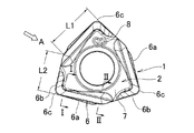
- the cutting insert 1 shown in FIGS. 1 to 4 has hexagonal first and second faces 2 and 3 each having alternating acute and obtuse corners.
- the first surface 2 and the second surface 3 are mutually opposite and used as a rake surface.
- Side surfaces 4 are connected to the first surface 2 and the second surface 3 respectively.
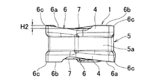
- the side surfaces 4 connected to the first surface 2 and the second surface 3 are separated from each other by the recess 5 provided between the both surfaces.
- the recess 5 has a bottom surface 5a in which six flat surfaces are sequentially connected at an angle.
- the bottom surface 5a is formed by a side having a cross section along a plane orthogonal to an axis along a line perpendicular to the thickness direction of the cutting insert having equal lengths of six lengths and corners where acute angles and obtuse angles are alternately arranged. It is hexagonal.
- a ridgeline at a position where the first surface 2 and the side surface 4 intersect and a ridgeline at a position where the second surface 3 and the side surface 4 intersect constitute the cutting edge 6.
- the cutting edge 6 is composed of a first cutting edge 6a, a second cutting edge 6b, and a corner edge 6c to which a nose R is attached.
- the corner blades 6c are respectively disposed at three acute corners. Further, the first cutting edge 6a and the second cutting edge 6b are respectively installed between the corner edges.
- the first cutting edge 6a has a length L1 including the corner cutting edge shown in FIG. 2 longer than the length L2 of the second cutting edge 6b.
- the first cutting edge 6a reaches from one end of each corner edge 6c to the obtuse corner where the separation distance is larger, and the second edge 6b has the smaller separation distance from the other end of each corner edge 6c. I'm heading for a dull corner.
- the first cutting edge 6a is inclined in a direction to raise the position of the cutting edge (in a direction in which the side of the corner blade 6c is away from the seating surface 7), and an end opposite to the side of the corner blade 6c (on the obtuse corner side) The end of the first cutting edge is at a position lower than the seating surface 7 (the side of the recess 5).
- the protrusion amount H2 (see FIG. 3) of the cutting edge corner from the seating surface 7 is the conventional shape
- the cutting edge strength is improved and chipping of the cutting edge is less likely to occur.
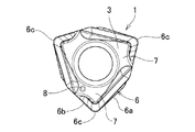
- Each of the first surface 2, the second surface 3, the bottom surface 5 a of the recess, and the cutting edge 6 has a shape in which the outline before and after rotation is overlapped by rotation of 120 ° around the insert center.
- the first surface 2 and the second surface 3 have the same shape, and the second cutting edge 6b of the second surface 3 is at the corner on the side where the first cutting edge 6a of the first surface 2 is located. As is the case, the first surface 2 and the second surface 3 are out of phase.
- the illustrated cutting insert 1 can be used by corner change of the three cutting edges of each of the first surface 2 and the second surface 3.
- the recess 5 is provided to separate the side surface 4 on the first surface 2 side and the side surface 4 on the second surface 3 side from each other. Since the bottom surface is configured to be received by the side surface of the insert support seat, complicated processing is avoided, and the clamping accuracy and the clamping stability of the cutting insert can be enhanced.
- the side face 4 on the side of the first face 2 and the side face 4 on the side of the second face 3 are separated by the recess 5 to make the side not supported by the insert support seat, the first cutting edge Make the corner blade 6c side of the side 4 forming 6a an angle of 90 ° with the seating surface 7 as shown in Fig. 5, and the side away from the corner blade 6c (obtuse angle corner side) is 90 ° or less It will also be possible.
- the corner portion already used for processing is attached to the cutter body as the restraining surface side, the progress of wear occurs because the bottom surface 5a used as the restraining surface and the blade side surface are separated by the recess 5 Even in this case, the contact portion with the restraining surface is not affected (the side wear does not spread to the bottom surface 5a). Therefore, the stability of the attachment at the time of multi corner use is securable.
- the side 4 is a flank of the main cutting edge.
- the obtuse corner side of the side surface 4 is inclined or curved as shown in FIG. 7 and the side close to the concave portion 5 is inserted inward from the cutting edge side, the insert is placed on the corner edge side.
- the obtuse corner side which can not avoid being close to the work material, can easily secure the necessary clearance, and tool interference with the work material is less likely to occur.
- Reference numerals 8 in FIGS. 1, 2 and 4 are identification marks for identifying the first surface 2 and the second surface 3.
- the identification mark 8 can be attached to only one side so that the first surface 2 and the second surface 3 can be viewed.
- This identification mark 8 is a preferred but not essential element.
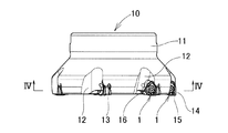
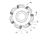
- FIGS. 8 to 12 of the accompanying drawings An example of a face milling cutter using such a cutting insert 1 is shown in FIGS. 8 to 12 of the accompanying drawings.
- the illustrated face milling cutter 10 secures the cutting insert 1 to a tool body (cutter body) 11 using a clamp screw 16.
- chip pockets 12 and insert support seats 13 facing each chip pocket are provided at a constant pitch in the circumferential direction.
- the insert support seat 13 has a main seating surface 13a (see FIG. 12) provided with a screw hole 17 for screwing in the clamp screw 16 and two seating side surfaces 13b and 13c (see FIGS. 11 and 12).
- FIG. 11 is an enlarged cross-sectional view of a position taken along the line III-III in FIG.
- FIG. 11 d of FIG. 11 and FIG. 12 is a thickness theft portion provided for the purpose of avoiding the interference of the cutting edge at a position not involved in cutting, the stress concentration on the corner portions of the main seat surface and the seat side surface, and the like.
- the cutting insert 1 makes either one of the first surface 2 and the second surface 3 (the first surface 2 in the figure) a rake surface, and the first cutting edge on the rake surface is face-milled.
- the main cutting edge 14 and the second cutting edge are mounted on the insert support seat 13 in such a direction as to become the Saraue blade 15.
- the main bearing surface 13a of the insert support seat supports a seating surface (the seating surface 7 in the figure is formed on the second surface 3) formed on the side opposite to the rake surface, and further, the insert support seat
- the two bearing surfaces 13b and 13c support two flat surfaces of the bottom surface 5a of the recess, which have an angle of 90 ° or less.
- the face milling cutter 10 thus configured can secure the same main cutting edge length as that of the conventional product by a cutting insert smaller in size than the conventional cutting insert.
- the rigidity of the tool body can be enhanced by reducing the size of the insert support seat provided on the tool body, and the cost can be reduced by reducing the material of the cutting insert.
- the cutting insert of this invention is not limited to the illustrated hexagon.
- the corner blade is a chamfered blade instead of the nose R, the first and second surfaces have nine corners. Such a shape may be sufficient.
- the bottom surface 5a of the recess 5 does not have to be hexagonal. It is sufficient that the contours of the bottom surfaces before and after rotation overlap by rotation by rotation of 120 ° around the insert center of the cutting edge.
Abstract
Description
前記第1の面に連なる前記側面と前記第2の面に連なる前記側面とを切り離す凹部とを有し、
前記切れ刃は、3つのコーナ刃と、各コーナ刃間に連なる第1の切れ刃及び第2の切れ刃とで構成され、
前記第1の切れ刃は前記第2の切れ刃よりも長さが長く、前記第1の切れ刃の前記コーナ刃側の端部が前記着座面よりも高い位置にあり、かつ、前記コーナ刃側の端部とは反対側の前記第1の切れ刃の端部が前記着座面よりも低い位置にあり、
前記第1の面、前記第2の面及び前記凹部の断面の各々は、インサート中心を支点にしたインサートの120°の回転で回転前後の輪郭が重なる形状を有し、
前記第1の面と前記第2の面とは同一形状であり、前記第1の面の前記第1の切れ刃がある側のコーナに前記第2の面の前記第2の切れ刃があるものにした。
2 第1の面
3 第2の面
4 側面
5 凹部
5a 底面
6 切れ刃
6a 第1の切れ刃
6b 第2の切れ刃
6c コーナ刃
7 着座面
8 識別マーク
10 正面フライスカッタ
11 工具本体
12 切屑ポケット
13 インサート支持座
13a 主座面
13b,13c 座側面
13d 肉盗み部
14 主切れ刃
15 サラエ刃
16 クランプねじ
17 ねじ孔
Claims (5)
- 各々が多角形の互いに背を向けた第1の面及び第2の面と、前記第1の面と前記第2の面とにそれぞれ連なる側面と、前記第1の面と前記側面が交差した位置の稜線及び前記第2の面と前記側面が交差した位置の稜線によってそれぞれ形成される切れ刃と、前記第1の面および前記第2の面のインサート中心側にそれぞれ形成される平行配置の着座面と、
前記第1の面に連なる前記側面と前記第2の面に連なる前記側面とを切り離す凹部とを有し、
前記切れ刃は、3つのコーナ刃と、各コーナ刃間に連なる第1の切れ刃及び第2の切れ刃とで構成され、
前記第1の切れ刃は前記第2の切れ刃よりも長さが長く、前記第1の切れ刃の前記コーナ刃側の端部が前記着座面よりも高い位置にあり、かつ、前記コーナ刃側の端部とは反対側の前記第1の切れ刃の端部が前記着座面よりも低い位置にあり、
前記第1の面、前記第2の面及び前記凹部の断面の各々は、インサート中心を支点にしたインサートの120°の回転で回転前後の輪郭が重なる形状を有し、
前記第1の面と前記第2の面とは同一形状であり、前記第1の面の前記第1の切れ刃がある側のコーナに前記第2の面の前記第2の切れ刃がある切削インサート。 - 前記第1の面及び前記第2の面は、鋭角コーナ、鈍角コーナ、長辺及び短辺を有する六角形であり、前記コーナ刃が各鋭角コーナに形成され、前記第1の切れ刃は前記長辺に形成され、前記第2の切れ刃は前記短辺に形成されている請求項1に記載の切削インサート。
- 前記凹部の断面が、6つの長さの等しい辺と、交互に鋭角と鈍角とが並ぶコーナにより形成される六角形である請求項1又は請求項2に記載の切削インサート。
- 前記第1の切れ刃において、前記側面と前記着座面とのなす角を前記コーナ刃側において90°、前記コーナ刃から離反した側では90°以下にした請求項1~請求項3のいずれか1つに記載の切削インサート。
- 請求項1~請求項4のいずれか1つに記載の切削インサートと、
前記切削インサートに接するインサート支持座を備える工具本体とで構成され、
前記インサート支持座は、前記切削インサートの着座面が接する主座面と前記切削インサートの凹部の底面に接する座側面を有するフライスカッタ。
Priority Applications (4)
| Application Number | Priority Date | Filing Date | Title |
|---|---|---|---|
| EP15793637.8A EP3150317B1 (en) | 2014-06-02 | 2015-04-16 | Cutting insert and milling cutter |
| BR112015032834A BR112015032834A2 (ja) | 2014-06-02 | 2015-04-16 | A cutting insertion and a fraise cutter |
| US14/902,445 US9884377B2 (en) | 2014-06-02 | 2015-04-16 | Cutting insert and milling cutter |
| CN201580001149.4A CN105339120B (zh) | 2014-06-02 | 2015-04-16 | 切削刀具和铣刀 |
Applications Claiming Priority (2)
| Application Number | Priority Date | Filing Date | Title |
|---|---|---|---|
| JP2014113972A JP5888656B2 (ja) | 2014-06-02 | 2014-06-02 | 切削インサートとフライスカッタ |
| JP2014-113972 | 2014-06-02 |
Publications (1)
| Publication Number | Publication Date |
|---|---|
| WO2015174200A1 true WO2015174200A1 (ja) | 2015-11-19 |
Family
ID=54479744
Family Applications (1)
| Application Number | Title | Priority Date | Filing Date |
|---|---|---|---|
| PCT/JP2015/061681 WO2015174200A1 (ja) | 2014-06-02 | 2015-04-16 | 切削インサートとフライスカッタ |
Country Status (6)
| Country | Link |
|---|---|
| US (1) | US9884377B2 (ja) |
| EP (1) | EP3150317B1 (ja) |
| JP (1) | JP5888656B2 (ja) |
| CN (1) | CN105339120B (ja) |
| BR (1) | BR112015032834A2 (ja) |
| WO (1) | WO2015174200A1 (ja) |
Cited By (8)
| Publication number | Priority date | Publication date | Assignee | Title |
|---|---|---|---|---|
| WO2018070058A1 (ja) * | 2016-10-14 | 2018-04-19 | 住友電工ハードメタル株式会社 | 切削インサート |
| EP3338928A1 (en) | 2016-12-22 | 2018-06-27 | Sandvik Intellectual Property AB | Cutting insert and shoulder milling tool |
| EP3338926A1 (en) | 2016-12-22 | 2018-06-27 | Sandvik Intellectual Property AB | Cutting insert and shoulder milling tool |
| EP3338927A1 (en) | 2016-12-22 | 2018-06-27 | Sandvik Intellectual Property AB | Cutting insert and shoulder milling tool |
| WO2018123421A1 (ja) | 2016-12-27 | 2018-07-05 | 住友電工ハードメタル株式会社 | 切削インサート |
| WO2018198445A1 (ja) | 2017-04-25 | 2018-11-01 | 住友電工ハードメタル株式会社 | 切削インサート |
| EP3403751A4 (en) * | 2016-01-13 | 2019-08-28 | Mitsubishi Materials Corporation | CUTTING INSERT AND CUTTING TOOL WITH REPLACEABLE BLADE TIP |
| DE112021001815T5 (de) | 2020-03-25 | 2023-01-05 | Kyocera Corporation | Rotationswerkzeug und verfaren zur herstellung eines maschinell bearbeiteten produkts |
Families Citing this family (9)
| Publication number | Priority date | Publication date | Assignee | Title |
|---|---|---|---|---|
| AT14072U1 (de) * | 2014-02-04 | 2015-04-15 | Ceratizit Luxembourg S R L | Doppelseitiger Frässchneideinsatz und Fräswerkzeug |
| EP3162481B1 (en) * | 2014-06-24 | 2022-12-21 | Sumitomo Electric Hardmetal Corp. | Cutting tool and tool body |
| EP3072616B1 (en) * | 2015-03-25 | 2018-10-10 | Sandvik Intellectual Property AB | Cutting insert and milling tool |
| EP3475019A1 (en) * | 2016-06-22 | 2019-05-01 | Iscar Ltd. | Ramping insert and high-feed milling tool assembly |
| US10035199B2 (en) * | 2016-06-30 | 2018-07-31 | Iscar, Ltd. | Cutting tool and triangular-shaped indexable cutting insert therefor |
| EP3315234A1 (en) * | 2016-10-25 | 2018-05-02 | Pramet Tools, S.R.O. | Metal cutting insert for milling |
| KR102015290B1 (ko) * | 2017-11-14 | 2019-08-28 | 한국야금 주식회사 | 절삭 인서트 및 이를 장착한 절삭 공구 |
| US10632548B2 (en) * | 2017-11-20 | 2020-04-28 | Iscar, Ltd. | Triangular-shaped indexable cutting insert having recessed side surfaces and rotary cutting tool |
| TWI787381B (zh) | 2017-11-30 | 2022-12-21 | 以色列商艾斯卡公司 | 單側三向可轉位切削嵌件及其嵌件式銑刀 |
Citations (5)
| Publication number | Priority date | Publication date | Assignee | Title |
|---|---|---|---|---|
| JP2009226577A (ja) * | 2008-02-29 | 2009-10-08 | Kyocera Corp | 切削インサートおよびそれを装着した転削工具 |
| JP2010524709A (ja) * | 2007-04-26 | 2010-07-22 | テグ テック インディア ピー.リミテッド | フライス削りカッタ用切削インサート |
| WO2013125542A1 (ja) * | 2012-02-20 | 2013-08-29 | 株式会社タンガロイ | 切削インサートおよび刃先交換式切削工具 |
| US20140010605A1 (en) * | 2012-07-06 | 2014-01-09 | Iscar, Ltd. | Rotary Cutting Tool and Reversible Cutting Insert Therefor |
| WO2014081011A1 (ja) * | 2012-11-22 | 2014-05-30 | 三菱マテリアル株式会社 | 切削インサート及びその製造方法 |
Family Cites Families (20)
| Publication number | Priority date | Publication date | Assignee | Title |
|---|---|---|---|---|
| WO1997027967A1 (de) * | 1996-01-31 | 1997-08-07 | Widia Gmbh | Schneideinsatz zum schruppen und schlichten |
| JP3951766B2 (ja) | 2002-03-20 | 2007-08-01 | 三菱マテリアル株式会社 | スローアウェイチップおよびスローアウェイ式切削工具 |
| IL169491A (en) | 2005-06-30 | 2009-06-15 | Carol Smilovici | Cutting insert |
| SE529068C2 (sv) * | 2005-09-28 | 2007-04-24 | Seco Tools Ab | Frässkär och fräsverktyg |
| IL182343A0 (en) * | 2007-04-01 | 2007-07-24 | Iscar Ltd | Cutting insert and tool for milling and ramping at high feed rates |
| JP5016671B2 (ja) | 2007-04-26 | 2012-09-05 | 京セラ株式会社 | 切削インサートおよび切削工具並びにそれを用いた切削方法 |
| US8454277B2 (en) | 2008-12-18 | 2013-06-04 | Kennametal Inc. | Toolholder and toolholder assembly with elongated seating pads |
| RU2539277C2 (ru) * | 2010-09-27 | 2015-01-20 | Тунгалой Корпорейшн | Режущая пластина и режущий инструмент |
| KR101239036B1 (ko) | 2011-01-17 | 2013-03-04 | 대구텍 유한회사 | 직각 가공용 절삭 인서트 및 이를 구비한 밀링 커터 |
| EP3287218A1 (en) * | 2011-05-31 | 2018-02-28 | Kyocera Corporation | Cutting insert, cutting tool, and method of manufacturing machined product using the same |
| US9475133B2 (en) * | 2011-06-30 | 2016-10-25 | Kyocera Corporation | Cutting insert, cutting tool, and method of manufacturing machined product using the same |
| JP5701385B2 (ja) * | 2011-06-30 | 2015-04-15 | 京セラ株式会社 | 切削インサートおよび切削工具ならびにそれを用いた切削加工物の製造方法 |
| AT12630U1 (de) | 2011-08-26 | 2012-09-15 | Ceratizit Austria Gmbh | Doppelseitiger schneideinsatz zum fräsen |
| EP2596889B1 (en) | 2011-11-23 | 2017-04-26 | Sandvik Intellectual Property AB | A cutting insert and a milling tool |
| JP2013121642A (ja) * | 2011-12-12 | 2013-06-20 | Mitsubishi Materials Corp | 切削インサートおよび刃先交換式エンドミル |
| JP6127439B2 (ja) * | 2011-12-12 | 2017-05-17 | 三菱マテリアル株式会社 | 刃先交換式切削工具および切削インサート |
| US8573905B2 (en) * | 2012-03-22 | 2013-11-05 | Iscar, Ltd. | Triangular cutting insert and cutting tool |
| JP2014087881A (ja) * | 2012-10-30 | 2014-05-15 | Mitsubishi Materials Corp | 切削インサートおよび刃先交換式切削工具 |
| EP2893997B1 (en) * | 2014-01-08 | 2019-03-13 | Sandvik Intellectual Property AB | A milling tool |
| USD744557S1 (en) * | 2014-05-12 | 2015-12-01 | Sumitomo Electric Hardmetal Corp. | Cutting insert |
-
2014
- 2014-06-02 JP JP2014113972A patent/JP5888656B2/ja active Active
-
2015
- 2015-04-16 US US14/902,445 patent/US9884377B2/en active Active
- 2015-04-16 BR BR112015032834A patent/BR112015032834A2/ja not_active Application Discontinuation
- 2015-04-16 EP EP15793637.8A patent/EP3150317B1/en active Active
- 2015-04-16 WO PCT/JP2015/061681 patent/WO2015174200A1/ja active Application Filing
- 2015-04-16 CN CN201580001149.4A patent/CN105339120B/zh active Active
Patent Citations (5)
| Publication number | Priority date | Publication date | Assignee | Title |
|---|---|---|---|---|
| JP2010524709A (ja) * | 2007-04-26 | 2010-07-22 | テグ テック インディア ピー.リミテッド | フライス削りカッタ用切削インサート |
| JP2009226577A (ja) * | 2008-02-29 | 2009-10-08 | Kyocera Corp | 切削インサートおよびそれを装着した転削工具 |
| WO2013125542A1 (ja) * | 2012-02-20 | 2013-08-29 | 株式会社タンガロイ | 切削インサートおよび刃先交換式切削工具 |
| US20140010605A1 (en) * | 2012-07-06 | 2014-01-09 | Iscar, Ltd. | Rotary Cutting Tool and Reversible Cutting Insert Therefor |
| WO2014081011A1 (ja) * | 2012-11-22 | 2014-05-30 | 三菱マテリアル株式会社 | 切削インサート及びその製造方法 |
Cited By (21)
| Publication number | Priority date | Publication date | Assignee | Title |
|---|---|---|---|---|
| US11045886B2 (en) | 2016-01-13 | 2021-06-29 | Mitsubishi Materials Corporation | Cutting insert and indexable cutting tool |
| EP3403751A4 (en) * | 2016-01-13 | 2019-08-28 | Mitsubishi Materials Corporation | CUTTING INSERT AND CUTTING TOOL WITH REPLACEABLE BLADE TIP |
| WO2018070058A1 (ja) * | 2016-10-14 | 2018-04-19 | 住友電工ハードメタル株式会社 | 切削インサート |
| US10875105B2 (en) | 2016-10-14 | 2020-12-29 | Sumitomo Electric Hardmetal Corp. | Cutting insert |
| JPWO2018070058A1 (ja) * | 2016-10-14 | 2019-09-05 | 住友電工ハードメタル株式会社 | 切削インサート |
| WO2018114131A1 (en) | 2016-12-22 | 2018-06-28 | Sandvik Intellectual Property Ab | Cutting insert and shoulder milling tool |
| US11161187B2 (en) | 2016-12-22 | 2021-11-02 | Sandvik Intellectual Property Ab | Cutting insert and shoulder millng tool |
| JP7200111B2 (ja) | 2016-12-22 | 2023-01-06 | サンドビック インテレクチュアル プロパティー アクティエボラーグ | 切削インサートおよび肩削りフライス工具 |
| US11229960B2 (en) | 2016-12-22 | 2022-01-25 | Sandvik Intellectual Property Ab | Cutting insert and shoulder milling tool |
| WO2018114134A1 (en) | 2016-12-22 | 2018-06-28 | Sandvik Intellectual Property Ab | Cutting insert and shoulder milling tool |
| EP3338927A1 (en) | 2016-12-22 | 2018-06-27 | Sandvik Intellectual Property AB | Cutting insert and shoulder milling tool |
| JP2020501924A (ja) * | 2016-12-22 | 2020-01-23 | サンドビック インテレクチュアル プロパティー アクティエボラーグ | 切削インサートおよび肩削りフライス工具 |
| US11229961B2 (en) | 2016-12-22 | 2022-01-25 | Sandvik Intellectual Property Ab | Cutting insert and shoulder millng tool |
| EP3338926A1 (en) | 2016-12-22 | 2018-06-27 | Sandvik Intellectual Property AB | Cutting insert and shoulder milling tool |
| EP3338928A1 (en) | 2016-12-22 | 2018-06-27 | Sandvik Intellectual Property AB | Cutting insert and shoulder milling tool |
| WO2018114132A1 (en) | 2016-12-22 | 2018-06-28 | Sandvik Intellectual Property Ab | Cutting insert and shoulder milling tool |
| US11110526B2 (en) | 2016-12-27 | 2021-09-07 | Sumitomo Electric Hardmetal Corp. | Cutting insert |
| WO2018123421A1 (ja) | 2016-12-27 | 2018-07-05 | 住友電工ハードメタル株式会社 | 切削インサート |
| US10875106B2 (en) | 2017-04-25 | 2020-12-29 | Sumitomo Electric Hardmetal Corp. | Cutting insert |
| WO2018198445A1 (ja) | 2017-04-25 | 2018-11-01 | 住友電工ハードメタル株式会社 | 切削インサート |
| DE112021001815T5 (de) | 2020-03-25 | 2023-01-05 | Kyocera Corporation | Rotationswerkzeug und verfaren zur herstellung eines maschinell bearbeiteten produkts |
Also Published As
| Publication number | Publication date |
|---|---|
| EP3150317B1 (en) | 2018-04-04 |
| EP3150317A4 (en) | 2017-06-07 |
| JP2015226960A (ja) | 2015-12-17 |
| BR112015032834A2 (ja) | 2020-04-28 |
| EP3150317A1 (en) | 2017-04-05 |
| US20160375506A1 (en) | 2016-12-29 |
| JP5888656B2 (ja) | 2016-03-22 |
| US9884377B2 (en) | 2018-02-06 |
| CN105339120A (zh) | 2016-02-17 |
| CN105339120B (zh) | 2017-06-09 |
Similar Documents
| Publication | Publication Date | Title |
|---|---|---|
| WO2015174200A1 (ja) | 切削インサートとフライスカッタ | |
| US9266175B2 (en) | Cutting insert and a milling tool | |
| US7905687B2 (en) | Cutting insert, tool holder, and related method | |
| JP6580572B2 (ja) | 割出し可能な両面切削インサートおよびそれ用の切削工具 | |
| JP6334515B2 (ja) | ショルダーミーリングカッター用の刃先割出し可能インサート及び刃先割出し可能インサートのための取付け切欠きを有するショルダーミーリングカッター | |
| JP4578577B2 (ja) | 切削インサート、切削工具、およびそれらを用いる切削方法 | |
| US7357604B2 (en) | Indexable cutting insert with positive axial rake angle and multiple cutting edges | |
| US7591614B2 (en) | Cutting insert with serrations | |
| US9468983B2 (en) | Rotary cutting tool and reversible cutting insert having variable-width minor relief surfaces therefor | |
| CN103282150B (zh) | 具有限定多个支撑面的开槽面的切削刀片 | |
| CN108472751B (zh) | 切削刀片及可转位刀片式切削工具 | |
| EP2805786B1 (en) | Indexable cutting insert having side supporting valley, and a milling tool | |
| TWI453079B (zh) | 切削用插件 | |
| EP2188085B1 (en) | Cutting insert | |
| US20080226403A1 (en) | Indexable cutting insert with positive axial rake angle and multiple cutting edges | |
| JP5779830B2 (ja) | 縦型刃先交換式切削インサートと隅削りフライスカッタ | |
| US9700947B2 (en) | Ballnose cutting tool and ballnose cutting insert | |
| KR20100090277A (ko) | 접선식 절삭 삽입체 | |
| US20120003052A1 (en) | Family of rotating cutting tools | |
| WO2014007407A1 (ja) | フライス加工用刃先交換式切削インサート | |
| WO2018123421A9 (ja) | 切削インサート | |
| JP5779831B2 (ja) | 縦型刃先交換式切削インサートとフライスカッタ | |
| WO2016163341A1 (ja) | 切削インサートおよび刃先交換式切削工具 | |
| WO2015030183A1 (ja) | 切削インサート及び刃先交換式切削工具 | |
| JP2021094609A (ja) | 切削インサート |
Legal Events
| Date | Code | Title | Description |
|---|---|---|---|
| WWE | Wipo information: entry into national phase |
Ref document number: 201580001149.4 Country of ref document: CN |
|
| 121 | Ep: the epo has been informed by wipo that ep was designated in this application |
Ref document number: 15793637 Country of ref document: EP Kind code of ref document: A1 |
|
| REEP | Request for entry into the european phase |
Ref document number: 2015793637 Country of ref document: EP |
|
| WWE | Wipo information: entry into national phase |
Ref document number: 2015793637 Country of ref document: EP |
|
| WWE | Wipo information: entry into national phase |
Ref document number: 14902445 Country of ref document: US |
|
| REG | Reference to national code |
Ref country code: BR Ref legal event code: B01A Ref document number: 112015032834 Country of ref document: BR |
|
| NENP | Non-entry into the national phase |
Ref country code: DE |
|
| ENP | Entry into the national phase |
Ref document number: 112015032834 Country of ref document: BR Kind code of ref document: A2 Effective date: 20151229 |
|
| REG | Reference to national code |
Ref country code: BR Ref legal event code: B01E Ref document number: 112015032834 Country of ref document: BR Kind code of ref document: A2 Free format text: APRESENTE TRADUCAO SIMPLES DA CERTIDAO DE DEPOSITO DA PRIORIDADE NO PAIS DE ORIGEM OU DECLARACAO ASSINADA, AMBAS CONTENDO TODOS OS DADOS IDENTIFICADORES DA PRIORIDADE CONFORME ART. 16, 2O, DA LPI. |
|
| ENP | Entry into the national phase |
Ref document number: 112015032834 Country of ref document: BR Kind code of ref document: A2 Effective date: 20151229 |