WO2015156243A1 - 熱処理装置、熱処理方法及びレール鋼 - Google Patents
熱処理装置、熱処理方法及びレール鋼 Download PDFInfo
- Publication number
- WO2015156243A1 WO2015156243A1 PCT/JP2015/060713 JP2015060713W WO2015156243A1 WO 2015156243 A1 WO2015156243 A1 WO 2015156243A1 JP 2015060713 W JP2015060713 W JP 2015060713W WO 2015156243 A1 WO2015156243 A1 WO 2015156243A1
- Authority
- WO
- WIPO (PCT)
- Prior art keywords
- rail
- heating
- heat treatment
- coil
- rail steel
- Prior art date
- Legal status (The legal status is an assumption and is not a legal conclusion. Google has not performed a legal analysis and makes no representation as to the accuracy of the status listed.)
- Ceased
Links
Images






Classifications
-
- C—CHEMISTRY; METALLURGY
- C21—METALLURGY OF IRON
- C21D—MODIFYING THE PHYSICAL STRUCTURE OF FERROUS METALS; GENERAL DEVICES FOR HEAT TREATMENT OF FERROUS OR NON-FERROUS METALS OR ALLOYS; MAKING METAL MALLEABLE, e.g. BY DECARBURISATION OR TEMPERING
- C21D9/00—Heat treatment, e.g. annealing, hardening, quenching or tempering, adapted for particular articles; Furnaces therefor
- C21D9/50—Heat treatment, e.g. annealing, hardening, quenching or tempering, adapted for particular articles; Furnaces therefor for welded joints
-
- C—CHEMISTRY; METALLURGY
- C21—METALLURGY OF IRON
- C21D—MODIFYING THE PHYSICAL STRUCTURE OF FERROUS METALS; GENERAL DEVICES FOR HEAT TREATMENT OF FERROUS OR NON-FERROUS METALS OR ALLOYS; MAKING METAL MALLEABLE, e.g. BY DECARBURISATION OR TEMPERING
- C21D1/00—General methods or devices for heat treatment, e.g. annealing, hardening, quenching or tempering
- C21D1/34—Methods of heating
- C21D1/42—Induction heating
-
- C—CHEMISTRY; METALLURGY
- C21—METALLURGY OF IRON
- C21D—MODIFYING THE PHYSICAL STRUCTURE OF FERROUS METALS; GENERAL DEVICES FOR HEAT TREATMENT OF FERROUS OR NON-FERROUS METALS OR ALLOYS; MAKING METAL MALLEABLE, e.g. BY DECARBURISATION OR TEMPERING
- C21D9/00—Heat treatment, e.g. annealing, hardening, quenching or tempering, adapted for particular articles; Furnaces therefor
- C21D9/04—Heat treatment, e.g. annealing, hardening, quenching or tempering, adapted for particular articles; Furnaces therefor for rails
-
- Y—GENERAL TAGGING OF NEW TECHNOLOGICAL DEVELOPMENTS; GENERAL TAGGING OF CROSS-SECTIONAL TECHNOLOGIES SPANNING OVER SEVERAL SECTIONS OF THE IPC; TECHNICAL SUBJECTS COVERED BY FORMER USPC CROSS-REFERENCE ART COLLECTIONS [XRACs] AND DIGESTS
- Y02—TECHNOLOGIES OR APPLICATIONS FOR MITIGATION OR ADAPTATION AGAINST CLIMATE CHANGE
- Y02P—CLIMATE CHANGE MITIGATION TECHNOLOGIES IN THE PRODUCTION OR PROCESSING OF GOODS
- Y02P10/00—Technologies related to metal processing
- Y02P10/25—Process efficiency
Definitions
- the present invention relates to a heat treatment apparatus, a heat treatment method, and rail steel.
- This application claims priority based on Japanese Patent Application No. 2014-79489 filed in Japan on April 8, 2014 and Japanese Patent Application No. 2014-79503 filed in Japan on April 8, 2014. Is hereby incorporated by reference.
- Rail steel welds are prone to rail breakage during use. Rail breakage occurs due to impact and vibration caused by train passage.
- One form of rail failure is brittle fracture due to cracks occurring in the weld. Brittle fracture includes fractures that originate from rail pillars or rail feet, and both must be prevented.
- HAZ Heat Affected Zone
- Patent Document 1 and Patent Document 2 as an invention related to heat treatment for suppressing fracture of a welded portion, the entire HAZ or a rail head portion and a column portion (abdomen) of HAZ having a temperature of 400 ° C. or higher are rapidly cooled.
- a method is disclosed.
- the method of heating the entire HAZ or the rail head portion and column portion (abdomen) of the HAZ to 400 ° C. or higher may be any method such as self-contained heat, flame, or high-frequency induction heating. Has been.
- Patent Document 3 as a method for preventing breakage starting from the foot of the rail base material, but not from the welded portion, the central portion in the width direction of the back surface of the foot of the rail base material is again set to 500 ° C. to 600 ° C. A method of heating is disclosed.
- gas flame heating and high frequency heating are mentioned as the reheating method.
- Patent Document 1 and Patent Document 2 have a certain effect in suppressing brittle fracture starting from the HAZ rail column, but prevent brittle fracture starting from the HAZ rail foot. Difficult to do.
- HAZ welded part
- Patent Document 3 a method of reheating the center part in the width direction of the back side of the foot part of the rail base material to 500 to 600 ° C. is invented.
- the present invention has been made in view of such circumstances, and an object thereof is to provide a heat treatment apparatus, a heat treatment method, and rail steel suitable for suppressing the occurrence of brittle fracture starting from a foot portion in a welded portion of rail steel. To do.
- the inventors In the brittle fracture starting from the rail foot portion of the HAZ, the inventors have the highest frequency at which the central portion in the rail length direction of the HAZ is the starting point of cracking, and then the vicinity of the boundary between the HAZ and the rail base material It has been found that (the vicinity including the base material at the position where the heating temperature during welding becomes the Ac1 point) is frequently the starting point of crack generation.
- the inventors of the present invention are that the starting point of these cracks is that the hardness (Hv value) changes abruptly with respect to the hardest part in the HAZ (longitudinal central part) and the length direction of the rail (including HAZ). Attention was focused on the portion (see Example 6 and FIG. 8).
- the present inventors suppress a rapid change in hardness and reduce the hardness with respect to the vicinity of the boundary between the HAZ and the rail base material.
- the inventors have conceived that cracking can be suppressed by performing the heat treatment (softening treatment). Furthermore, by heating only the surface layer at a heating temperature of 600 ° C. to 800 ° C. and softening, it suppresses the generation of cracks as the starting point of brittle fracture, and suppresses the progress of cracks even if they occur It has been conceived that, when the rail head is softened, the rail foot is likely to crack, and the present invention has been completed.
- a heat treatment apparatus is a heat treatment apparatus that includes a coil and heats the back surface of a foot portion of a welded portion of rail steel by induction heating.
- the heated region is HAZ
- the length of the HAZ in the rail length direction on the back surface of the foot is Lh
- the width of the rail steel is W
- the back surface of the foot is viewed from the opposite line of sight
- the coil The length of the outer region of the rail in the rail length direction is 1.2 times or more of Lh
- the length of the outer region of the coil in the width direction of the rail is 1.1 times or more of W. It is.
- the length of the outer region of the coil in the rail length direction may be 40 mm or more.
- the length of the outer region of the coil in the rail width direction is 1.2 times or more of W. May be.
- a heat treatment method is a heat treatment method for a welded portion of rail steel, and the coil of the heat treatment apparatus according to any one of the above (1) to (4) is When facing the back surface of the foot portion, the back surface of the foot portion is sandwiched between a pair of imaginary lines that are symmetric with respect to the welding center plane and are 1.2 times as long as the Lh.
- a heating rate of 3 ° C./second or more and 20 ° C./second or less a position C at least on the center surface of the rail steel in the width direction of the rail steel and on the center surface of the rail steel is 600.
- the heating step may employ a configuration in which the position C is heated to a temperature higher than 600 ° C. and an Ac1 point or lower.
- the position C is heated to a temperature higher than Ac1 point and not higher than 800 ° C., and the cooling step is performed by cooling. Also good.
- the heating step may employ a configuration in which the heating temperature of the head of the rail steel is 600 ° C. or less. Good.
- the rail steel according to one aspect of the present invention is a rail steel having a welded portion, Heat treatment is performed on the welded portion by the heat treatment method for a welded portion of rail steel according to any one of the above (5) to (8).
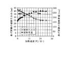
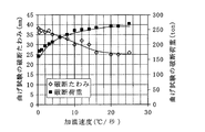
- Example 6 is a graph showing measurement results of a bending test in Example 2.
- 10 is a graph showing the evaluation test results in Example 3. It is a graph which shows the evaluation test result in Example 4.
- 10 is a graph showing the evaluation test results in Example 5. It is a graph which shows the evaluation test result in Example 6. It is a graph which shows the evaluation test result in Example 7.
- Example 8 a graph showing temperature measurement results when L 2 is 1.2 times that of W.
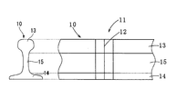
- FIGS. 2A and 2B are cross-sectional views perpendicular to the length direction of the rail 10 and a partial side view thereof
- FIG. 2B is a cross-sectional view perpendicular to the length direction of the rail 10 and a partial bottom view thereof.
- the rail 10 has at least two rails as welded materials welded between end faces, and has a welded portion 11.
- the welded portion 11 includes a weld center plane 12 which is a portion where the end surfaces of the rail before welding, which is a workpiece, are in contact with each other.
- the rail 10 is located above, and the rail head (head 13) where contact with the wheels occurs, the rail foot (foot 14) located below and in contact with the sleepers, and the head 13 and foot 14 and a rail column portion (column portion 15) that is provided vertically between the head portion 13 and the foot portion 14.
- the steel forming the rail steel 10 is not particularly limited, and hypoeutectoid steel, eutectoid steel, hypereutectoid steel, etc. having a carbon content of about 0.6 to 1.0% by mass can be used.
- the area heated to the Ac1 point or higher during welding is HAZ17
- the length of the HAZ17 in the rail length direction at the center position 18 in the width direction of the rail 10 on the back surface of the foot 14 is Lh
- the width of the rail 10 is increased. Define W.
- the Ac1 point refers to a temperature at which the metal structure starts to transform in the vicinity of 720 to 750 ° C. in the process of heating the steel material from a temperature range of 700 ° C. or less.
- Ac1 point is the temperature at which the cementite phase begins to transform into an austenite phase in hypoeutectoid steel, the ferrite phase transforms into austenite phase in hypereutectoid steel, and the ferrite phase and cementite phase begin to transform into austenite phase in eutectoid steel.
- the temperature of Ac1 point differs depending on the carbon content of the steel material and the alloy components. As a method for accurately obtaining the Ac1 point, it can be obtained by observing the microstructure in the cross section of the welded portion 11.
- the HAZ 17 can be clearly observed as a region where the structure is changed by being heated to the Ac1 point or higher.
- Examples of the method for observing the micro and macro structures in the cross section of the welded portion 11 include a method of etching the cross section using a nitric alcohol solution or dilute hydrochloric acid.
- the size of the HAZ 17 is determined by the amount of heat input during welding. If the welding conditions are the same, the size of the HAZ 17 is also the same. Lh can be confirmed by observing the macro structure in a cross section in the rail length direction passing through the center position 18 in the width direction of the rail 10.
- the weld center plane 12 is a plane that passes through the center of the HAZ 17 and is perpendicular to the rail length direction and parallel to the rail width direction.
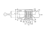
- the heat treatment apparatus 20 As shown in FIGS. 1A and 1B, the heat treatment apparatus 20 according to the first embodiment of the present invention has a coil 21.
- the heat treatment apparatus 20 induction-heats the back surface of the foot part 14 of the welded part 11 of the rail 10.
- the coil 21 has a rectangular shape when viewed from the direction of the axis 23 (the central axis in the rail length direction of the outer region 22 when the coil 21 is installed on the back surface of the foot 14) (state in FIG. 1B). It is the coil of 1 volume which has. That is, the shape of the outer region 22 of the coil 21 is a rectangular shape.
- the direction of the axis 23 is the direction of the back surface of the foot 14 as viewed from the opposite line of sight, and is the direction of the magnetic field generated in the coil 21 when a current is passed through the coil 21.
- No particular limitation is imposed on the upper limit of the lateral length L 1, but is for example Lh of 3 times or more. If L 1 is more than three times Lh, the effect of suppressing the occurrence of brittle fracture is saturated.
- the horizontal direction is too long
- L 1 is the length, that is, when the area to be softened too spread the rail longitudinal direction, by bending in use increases, in some cases a crack is liable to occur.
- the length L 2 of the longitudinal direction of the outer region 22 of the coil 21 (the rail width direction of the outer region 22 when the coil 21 is installed on the back surface of the foot 14) is the width W 2. 1.1 times or more. That is, when viewed from the direction of the shaft 23, the outer edge in the width direction of the rail 10 is separated from the outer edge (outer edge) of the coil 21 by a distance of 0.05 times the width W or more.
- longitudinal length L 2 is at least 1.1 times the width W, it is possible to reduce the temperature rise difference is formed across the width direction of the rail 10.
- Longitudinal length L 2 is preferably at least 1.2 times the width W.
- the outer edge in the width direction of the rail 10 is separated from the outer edge (outer edge) of the coil 21 by a distance of 0.1 times the width W or more.
- the longitudinal length L 2 by 1.2 times or more the width W, it is possible to further reduce the temperature rise difference is formed across the width direction of the rail 10.
- Longitudinal not particularly limited as the upper limit of the length L 2 is, for example, three times the width W. If the longitudinal length L 2 is more than three times the width W, the effect is saturated to reduce the temperature rise of the width direction of the rail 10.
- the width W of the general rail 10 is about 50 mm to 150 mm including the light rail, and about 100 mm to 150 mm in the case of a normal rail for a commercial railway.
- a copper coil can be used, and a pipe-shaped coil such as a copper pipe can also be used.
- a pipe-shaped coil such as a copper pipe
- the cross-sectional shapes of the metal wire and metal pipe forming the coil 21 include, but are not limited to, a circle, an ellipse, and a substantially square.
- the outer diameter and long side length of the metal wire and metal pipe are not particularly limited, but are preferably about 5 mm or more and 40 mm or less.
- the heat treatment apparatus 20 has a high-frequency power source (not shown) that is electrically connected to the coil 21.
- the high-frequency power source is not particularly limited as long as it is a power source that generates a high-frequency current having a predetermined frequency, and a known high-frequency power source such as a transistor type, a thyristor type, or an electron tube type can be used.
- the heat treatment apparatus 20 can include a means for fixing the coil 21 and a means for measuring the temperature of the part to be heated (for example, a thermocouple or a radiation thermometer).
- the heat treatment method for the welded portion of the rail steel according to the second embodiment of the present invention includes the step (A) of inductively heating a predetermined region in the welded portion 11 using the heat treatment device 20, and the heated welded portion 11 after the heating. (B) which cools.
- Step (A) Induction heating is performed by placing the heat treatment apparatus 20 close to the back side of the foot 14. Specifically, as shown in FIGS. 1A and 1B, the shaft 23 of the coil 21 and the back surface of the foot 14 are sandwiched between a pair of virtual lines 24 when viewed vertically and from the direction of the shaft 23.
- the coil 21 of the heat treatment apparatus 20 is disposed opposite to the back surface of the foot portion 14 so that the outer region 22 includes the region 16.
- Each of the pair of virtual lines 24 is a straight line parallel to the welding center plane 12, is located symmetrically from the welding center plane 12, and the mutual distance is 1.2 times Lh.
- the outer region 22 becomes a heating region on the back surface of the foot portion 14 of the rail 10.
- Coil 21 the center coincides with the welding center plane 12 in the lateral direction of the outer glue area 22 (L 1 direction) of the coil 21, the center in the longitudinal direction (L 2 direction) coincides with the center position 18 of the rail width direction
- the distance between the coil 21 and the back surface of the foot portion 14 is not particularly limited as long as the coil 21 can induction heat the back surface of the foot portion 14. This distance can be, for example, about 5 mm to 50 mm.
- the induction heating is performed by arranging the heat treatment apparatus 20 as described above and heating the back surface of the foot 14 at a heating rate of 3 ° C./second or more and 20 ° C./second or less, preferably 5 ° C./second or more.
- a heating rate 3 ° C./second or more and 20 ° C./second or less, preferably 5 ° C./second or more.
- the heating rate is less than 3 ° C./second, the strength of the foot portion 14 is significantly reduced by heating and softening from the surface of the rail steel 10 to the deep range of the rail steel 10. Conversely, when the heating rate exceeds 20 ° C./second, the effect of suppressing the progress of cracks is saturated.
- the induction heating of this embodiment by heating at a heating rate of 3 ° C./second or more and 20 ° C./second or less, at least on the weld center plane 12 on the back surface of the foot 14 and on the center position 18 in the width direction of the rail steel 10.
- the surface at position C (see FIG. 2B) is heated to a temperature higher than 600 ° C. and lower than 800 ° C.
- the lower limit of the heating temperature is preferably 640 ° C, and more preferably 660 ° C.
- the upper limit of the heating temperature is preferably 780 ° C. If the upper limit of initial temperature is 600 degrees C or less, it will not specifically limit, Preferably it is 500 degrees C or less, More preferably, it can also be 400 degrees C or less.
- the lower limit of the initial temperature is not particularly limited, and may be room temperature (for example, 10 ° C. to 30 ° C.).
- the surface temperature can be measured with a radiation thermometer.
- the heating rate is a value (average value) obtained by dividing the rising temperature (° C.) from the initial temperature to a heating temperature of over 600 ° C. to 800 ° C. by the heating time (seconds).
- a head is not heated more than 600 degreeC.
- the rail steel 10 having an Ac1 point or less is basically two phases of a ferrite phase and a cementite phase in an equilibrium diagram.
- the rail steel can be obtained by spheroidizing cementite, expanding the ferrite crystal grain size, and tempering effect when bainite and martensite are present.
- Ten tissues can be softened.
- the occurrence of cracks can be suppressed, and the progress of cracks can be suppressed even when cracks occur.
- heat processing over 800 degreeC is performed with respect to the rail steel 10
- the heating time of induction heating in the present embodiment is preferably 10 seconds or longer and 265 seconds or shorter.
- the end portion in the width direction of the rail steel 10 is easily heated to a higher temperature than the center position 18 in the width direction of the rail steel 10.
- the longitudinal length L 2 of the outer glue area 22 of the coil 21 is 1.1 times or more of W
- the widthwise end portion of the rail steel 10 when subjected to induction heating and the widthwise center position 18 The difference in temperature rise can be reduced.
- the heating temperature at the end in the rail width direction is also limited to a temperature higher than 600 ° C. and not higher than 800 ° C. Can do.
- the preferable cooling process conditions differ between the heating temperature exceeding 600 ° C. and the Ac1 point or less and the heating temperature exceeding Ac1 point and the 800 ° C. or less. This will be described in detail later.
- the longitudinal length L 2 of the outer glue area 22 of the coil 21 is not less than 1.2 times the width W, as compared to when the longitudinal length L 2 is 1.1 times the width W,
- the temperature rise difference between the width direction end of the rail steel 10 and the width direction center position 18 can be reduced more effectively.
- the heating temperature at the end in the rail width direction can also be limited to more than 600 ° C. and less than Ac1 point. .
- the heating temperature is higher than 600 ° C. and lower than Ac1 point, it can be cooled by any method as described later.
- the frequency at which induction heating is performed is, for example, preferably 1 kHz to 100 kHz, and more preferably 2 kHz to 50 kHz. By increasing the frequency at which induction heating is performed, the heating of this embodiment can be easily controlled.
- a holding time time for maintaining the surface temperature after heating
- the holding time is preferably 20 seconds or less, and more preferably 10 seconds or less.
- the holding time is a time after heating under a predetermined heat input condition in which the heat input is lower than that during heating and the heat input is not zero. Therefore, the surface temperature may be lower than the heating temperature during the holding time.
- the cooling after a heating means the state which made heat input 0.
- the upper surface of the foot 14 and the column 15 may be heated.
- the head 13 is removed from the region to be heated.
- a softened layer is formed not only on the foot 14 but also on the head 13. Due to wear during wheel passage, the softened layer of the head 13 becomes a dent.
- This dent causes a downward displacement (elastic deformation) of the welded portion 11 when passing through the wheel, and promotes the occurrence of cracks on the back surface of the foot portion 14. Therefore, the crack generation
- heating the region excluding the head 13, that is, not heating the head 13 means that the head 13 is not actively or directly heated (not softened), and the heating temperature of the head 13 is In the heat treatment step, it means that the temperature does not exceed 600 ° C. (preferably above 400 ° C.).
- the cooling step is performed after the heating step.
- a preferable cooling process is different between the case where the heating temperature is higher than 600 ° C and the Ac1 point or lower and the case where the heating temperature is higher than the Ac1 point and not higher than 800 ° C.
- cooling can be carried out at any cooling method and at any cooling rate. That is, it may be allowed to cool (natural cooling: the cooling rate is, for example, 1 ° C./second or less), or accelerated cooling (forced cooling: the cooling rate is, for example, more than 1 ° C./second but not more than 20 ° C./second) May be.
- natural cooling the cooling rate is, for example, 1 ° C./second or less
- accelerated cooling force cooling: the cooling rate is, for example, more than 1 ° C./second but not more than 20 ° C./second
- the accelerated cooling method is not particularly limited, and can be performed by jetting water or air.
- the cooling is preferably performed by cooling.
- the heating temperature is higher than the Ac1 point, a ⁇ phase is generated in the structure, but the cementite phase is spheroidized by heating at a heating rate of 3 ° C./second to 20 ° C./second. Further, when cooling is performed by cooling, a spheroidized cementite phase remains in the structure. Thereby, a softening process can be performed more appropriately.
- the heating temperature is over the Ac1 point and is 800 ° C.
- the rail steel according to the third embodiment of the present invention is a rail steel 10 having a welded portion 11, and the heat treatment method according to the second embodiment is applied to the welded portion 11.
- the hardness of the head 13 in the welded portion 11 is not substantially different from that before the heat treatment, but the hardness of at least the back surface of the foot portion 14 in the welded portion 11 is softened. That is, the hardness of the head 13 of the welded part 11 is higher than the hardness of the back surface of the foot part 14 of the welded part 11.
- the weld center surface 12 that is most likely to be the starting point of crack fracture at least on the back surface of the foot portion 14 excluding the head is softened, and is likely to be the starting point of crack fracture next to the weld center surface 12.
- the region where the hardness outside the HAZ 17 changes abruptly is softened.
- the head 13 is not softened.
- the present invention is not limited to the above-described embodiment, and the configuration thereof can be changed without changing the gist of the present invention.
- the coil 21 is not limited to one turn and may be two or more turns.
- the shape of the coil 21 is not limited to a rectangular shape, and may be, for example, an elliptical shape.
- -Foot temperature measurement position center in the rail length direction (weld center plane) on the back of the foot of the HAZ and rail width direction
- center-Head temperature measurement position center in the rail length direction at the top of the head of the HAZ (welding Center plane) and rail width direction center
- Heating rate Average heating rate from initial temperature to heating temperature (°C / sec)
- -Temperature measurement method Measurement with a radiation thermometer-Heating means: Inductive heating (frequency: 10 kHz) with a single coil wound in a substantially rectangular shape.
- the coil was placed close to the heating area and heated so that the plane of the coil and the heating area were substantially parallel and symmetrical with respect to the center position in the welding center plane and the rail width direction.
- the area outside the coil was the heating area.
- Example 1 The rail steel weld was heat treated under the following conditions. -Heating area: Foot rear surface (example) or both foot rear surface and head (comparative example) -Initial temperature: 400 ° C ⁇ Heating temperature: 650 ° C -Heating rate: 5 ° C / second-Retention after heating: None-Cooling rate after heating: 5 ° C / second (accelerated cooling)
- the lateral length L 1 of the outer region of the coil is 1.2 times Lh
- Example 1 Each rail steel heat-treated in Example 1 and the test material (AW) in a post-weld state without heat treatment were evaluated by the following methods.
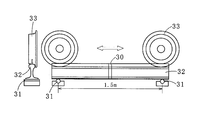
- a pair of cylindrical steel materials 31 was arranged at a position 1.5 m apart from the welded portion 30 to support the rail steel 32.
- the load was applied by reciprocating the loaded wheel 33 in the range of 1.5 m, and the number of reciprocations until the break and the amount of head wear were measured.
- FIG. 3B As shown in FIG. 3B, it can be seen that in the example in which only the foot portion is heated, the number of times until the breakage is remarkably high, and it has high resistance to brittle fracture. On the other hand, in the comparative example in which both the foot and the head are heated, it is understood that the amount of head wear increases and the resistance to brittle fracture is not improved so much.
- Example 2 The rail steel weld was heat treated under the following conditions. -Heating area: Back of the foot part-Initial temperature: 400 ° C ⁇ Heating temperature: 650 ° C Heating rate: Varyed in the range of 0.2 ° C./second to 25 ° C./second. -Retention after heating: None-Cooling rate after heating: 5 ° C / second (accelerated cooling)
- the lateral length L 1 of the outer region of the coil is 1.2 times Lh
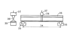
- Example 2 Evaluation in each rail steel heat-processed in Example 2 was performed with the following method. As shown in FIG. 4A, a pair of cylindrical steel members 35 having a radius of 50 mm are arranged at positions spaced 1 m from the welded portion 34 to support the rail steel 36. Pressure was applied from above the welded portion 34 with a cylindrical steel material 37 having a radius of 50 mm. The load rate of pressurization (load) was 10 mm / min.
- FIG. 4B shows the load when the rail steel 36 is broken (breaking load) and the amount of deflection when the rail steel 36 is broken (breaking deflection amount). As shown in FIG. 4B, when the heating rate is increased, the breaking load increases and the resistance to brittle fracture tends to increase.
- the heating rate is less than 3 ° C./second, the bending deflection is extremely large, and the breaking load is reduced. This is considered to be due to softening not only to the surface layer of the foot part but also to the deep part, resulting in a decrease in strength.
- the heating rate exceeds 20 ° C./second, a softened layer having a certain thickness is not formed and the resistance to brittle fracture is saturated.
- Example 3 The rail steel weld was heat treated under the following conditions.
- -Heating area Back of the foot part-Initial temperature: 400 ° C
- Heating temperature Changed in the range of 420 ° C to 1000 ° C.
- -Heating rate 5 ° C / second-Retention after heating: None-Cooling rate after heating: 5 ° C / second (accelerated cooling) and 0.9 ° C / second (cooling).
- the lateral length L 1 of the outer region of the coil is 1.2 times Lh
- Example 4 the resistance to brittle fracture is improved even when accelerated cooling is performed after heating at a temperature higher than 725 ° C. and not higher than 800 ° C.
- Example 4 The rail steel weld was heat treated under the following conditions. -Heating area: Foot rear surface (example) or both foot rear surface and head (comparative example) -Initial temperature: 400 ° C ⁇ Heating temperature: 750 °C -Heating rate: 5 ° C / second-Retention after heating: None-Cooling rate after heating: 5 ° C / second (accelerated cooling) and 0.9 ° C / second (cooling).
- the lateral length L 1 of the outer region of the coil is 1.2 times Lh
- Example 5 The rail steel weld was heat treated under the following conditions. -Heating area: Back of the foot part-Initial temperature: 400 ° C ⁇ Heating temperature: 750 °C Heating rate: Varyed in the range of 0.2 ° C./second to 25 ° C./second. -Retention after heating: None-Cooling rate after heating: 0.9 ° C / second (cooling)
- the lateral length L 1 of the outer region of the coil is 1.2 times Lh
- Example 7 The rail steel weld was heat treated under the following conditions. -Heating area: Back of the foot part-Initial temperature: 400 ° C ⁇ Heating temperature: 650 ° C -Heating rate: 5 ° C / second-Retention after heating: None-Cooling rate after heating: 5 ° C / second (accelerated cooling)
- the lateral length L 1 of the outer region of the coil was varied in the range of 0.8 to 3.0 times Lh. In the case L 1 is at least 1.2 times Lh are examples, others are comparative examples.
- Example 8 Immediately after the heat treatment in Example 8, that is, when the temperature at the center point in the rail width direction was 600 ° C., the temperature at position A and the temperature at position B were measured along the rail length direction. .
- the position A is a position 5 mm inward from one end and the other end in the width direction of the rail
- the position B is the center in the width direction of the rail.
- the temperature at a position 5 mm inward from one end in the width direction of the rail was equal to the temperature at a position 5 mm inward from the other end.
- the measurement results are shown in FIGS. 10A to 10C.
- FIG. 10A shows a case where L 2 is 1.0 times W
- FIG. 10B shows a case where L 2 is 1.1 times W
- FIG. 10C shows a case where L 2 is 1.2 times W. It is a measurement result.
- L 2 is, in the case of 1.0 times W, when heated the position B to 600 ° C., the temperature of the position A is greater than 800 ° C.. In this case, as shown in FIG. 5 and the like, the position A on the weld center plane is not sufficiently softened.
- FIG. 10B in the case where L 2 is 1.1 times W ((L 2 ⁇ W) / 2 is 0.05 times W), position B is heated to 600 ° C.
- the temperature of the position A can be suppressed to 800 ° C. or less. Thereby, the position A can be softened. However, since the temperature at the position A exceeds the Ac1 point (725 ° C.), in order to soften, it is necessary to cool by cooling after heating. As shown in FIG. 10C, when L 2 is 1.2 times W ((L 2 ⁇ W) / 2 is 0.1 times W), position B is heated to 600 ° C. The temperature of A can be suppressed to Ac1 point (725 ° C.) or less. Thereby, softening is possible even if it cools using any method of natural cooling and accelerated cooling after a heating.
Landscapes
- Chemical & Material Sciences (AREA)
- Engineering & Computer Science (AREA)
- Physics & Mathematics (AREA)
- Thermal Sciences (AREA)
- Crystallography & Structural Chemistry (AREA)
- Mechanical Engineering (AREA)
- Materials Engineering (AREA)
- Metallurgy (AREA)
- Organic Chemistry (AREA)
- Heat Treatment Of Articles (AREA)
Abstract
Description
本願は、2014年4月8日に日本に出願された特願2014-79489号及び2014年4月8日に日本に出願された特願2014-79503号に基づき優先権を主張し、その内容をここに援用する。
なお、本明細書では、溶接時にAc1点以上に加熱された領域をHAZ(Heat Affected Zone:熱影響部)と呼称する。溶接ビードが存在する場合は、溶接ビードはAc1点以上に加熱されており、溶接ビードもHAZに含まれる。
溶接部(HAZ)ではないが、レール母材の足部を起点とする破壊を防止する方法として、レール母材の足部裏面の幅方向中央部を500~600℃に再加熱する方法が発明されている(特許文献3)。このように再加熱することで、レール足部の裏面に圧縮残留応力を付与し、折損等の破壊が防止できるとされている。しかし、この方法は、溶接部の破壊を防止するものではなく、逆にレール底部の再加熱温度が600℃超である場合には、レール鋼の硬さが急激に低下し、レール折損時の破壊応力が低減することにより、レール底部からの折損が発生し易くなることが記載されている(特許文献3の段落[0014]等参照)。
また、いずれの先行技術文献にも、溶接部を誘導加熱するためのコイルの具体的な形状は記載されていない。
本発明者らは、HAZのレール足部を起点とする脆性破壊を防ぐために、HAZとレール母材との境界近傍に対し、硬さの急激な変化を抑制し、かつ硬さを低下させるための加熱処理(軟化処理)を施すことにより、亀裂発生を抑制できることに想到した。さらに、加熱処理における加熱温度を600℃超800℃以下として表層のみを加熱して軟化させることにより、脆性破壊の起点になる亀裂の発生を抑制し、亀裂が発生しても亀裂の進展を抑制できること、及びレール頭部に対して軟化処理を施した場合には、逆にレール足部に亀裂が生じやすくなることに想到し、本発明の完成に至った。
(1)本発明の一態様に係る熱処理装置は、コイルを有し、レール鋼の溶接部の足部裏面を誘導加熱により加熱する熱処理装置であって、前記溶接部において溶接時にAc1点以上に加熱された領域をHAZ、前記足部裏面におけるレール長さ方向の前記HAZの長さをLh、前記レール鋼の幅をWとし、前記足部裏面を対向する視線で見た場合に、前記コイルの外のり領域の前記レール長さ方向の長さが前記Lhの1.2倍以上であり、前記コイルの前記外のり領域の前記レールの幅方向の長さが前記Wの1.1倍以上である。
前記溶接部に上記(5)から上記(8)の何れか一態様に記載のレール鋼の溶接部の熱処理方法によって熱処理が施されている。
まず、溶接されたレール鋼10(以下、単にレール10ともいう)について、図2A及び図2Bを用いて説明する。図2Aはレール10の長さ方向に垂直な断面図及びその部分側面図、図2Bはレール10の長さ方向に垂直な断面図及びその部分底面図である。
レール10は、少なくとも2本の被溶接材としてのレールが端面間で溶接されており、溶接部11を有する。溶接部11は、被溶接物である溶接前のレールの端面同士が当接した部分である溶接中心面12を含む。また、レール10は、上方に位置し、車輪との接触が生じるレール頭部(頭部13)、下方に位置し、枕木と接するレール足部(足部14)、及び頭部13と足部14との間に垂直に設けられ、頭部13と足部14とを連結するレール柱部(柱部15)を備えている。レール鋼10を形成する鋼としては、特に限定されないが、炭素含有量が0.6~1.0質量%程度の亜共析鋼、共析鋼及び過共析鋼等を用いることができる。
Ac1点は、鋼材の炭素量及び合金成分により温度が異なる。Ac1点を正確に求める方法としては、溶接部11の断面におけるミクロ組織の観察により求めることができる。すなわち溶接部のレール幅方向中心でかつレール長手方向に平行な断面を、顕微鏡により溶接時の最高到達温度の低い母材側から溶接中心に向かって金属組織を観察し、パーライトが球状化した組織から、パーライト組織とパーライトが球状化した組織が混在した組織に変化する位置を求める方法がある。Ac1点を簡便に求めるには、炭素量を基準として、冶金学の教科書(例えば、鉄鋼材料、日本金属学会編)などに掲載されているFe-Fe3C系平衡状態図から読み取ることが可能である。実際のレール鋼10のAc1点は、平衡状態図の線よりも5~30℃高めの値となる。一般的な組成のレール鋼10のAc1点は、725℃以上750℃以下である。
Lhは、レール10の幅方向の中心位置18を通るレール長さ方向断面におけるマクロ組織の観察により確認できる。溶接中心面12は、HAZ17の中央を通り、レール長さ方向に垂直かつレール幅方向に平行な面である。
次に、熱処理装置について説明する。
図1A及び図1Bに示されるように、本発明の第1の実施の形態に係る熱処理装置20は、コイル21を有する。熱処理装置20は、レール10の溶接部11の足部14裏面を誘導加熱する。
横方向長さL1の具体的な上限としては、一般的なレール10のLhを考慮すると、例えば200mmである。
縦方向長さL2が幅Wの1.1倍以上であることにより、レール10の幅方向にわたって形成される温度上昇差を低減することができる。
縦方向長さL2の上限としては特に限定されないが、例えば幅Wの3倍である。縦方向長さL2が幅Wの3倍を超える場合は、レール10の幅方向の温度上昇差を低減する効果が飽和する。
なお、一般的なレール10の幅Wは、軽レールも含めると50mm~150mm程度であり、営業鉄道用の普通レールの場合は100mm~150mm程度である。
本発明の第2の実施の形態に係るレール鋼の溶接部の熱処理方法は、熱処理装置20を用いて溶接部11における所定の領域を誘導加熱する工程(A)と、加熱後、溶接部11を冷却する工程(B)とを有する。
誘導加熱は、熱処理装置20を足部14裏面側に近接配置して行う。具体的には、図1A及び図1Bに示されるように、コイル21の軸23と足部14裏面とが垂直に、かつ軸23の方向から見た場合に、一対の仮想線24で挟まれる領域16を外のり領域22が含むように、熱処理装置20のコイル21が足部14裏面に対向配置される。一対の仮想線24は、それぞれ溶接中心面12に平行な直線であり、溶接中心面12から対称に位置し、相互の距離がLhの1.2倍である。軸23の方向から見た場合に、つまり足部14裏面を対向する視線で見た場合に(図1Bの状態)、外のり領域22は、レール10の足部14裏面における加熱領域となる。
なお、コイル21と足部14裏面との距離は、コイル21が足部14裏面を誘導加熱することができる距離であれば、特に限定されない。この距離としては、例えば5mm以上50mm以下程度とすることができる。
レール鋼10の足部14裏面を急速に加熱する(加熱速度を3℃/秒以上20℃/秒以下とする)ことで、レール鋼10の表層のみを軟化させるとともに、レール鋼10の内部に硬い層を残しておくことができる。これにより、レール鋼10における亀裂の発生及び進行を抑制できる。
加熱速度が3℃/秒未満の場合は、レール鋼10の表面からレール鋼10の深い範囲まで加熱及び軟化されることにより、足部14の強度が顕著に低下する。逆に、加熱速度が20℃/秒を超える場合は、亀裂の進行を抑制する効果が飽和する。
加熱温度の下限値としては640℃が好ましく、660℃がさらに好ましい。加熱温度の上限値としては、780℃が好ましい。
初期温度の上限は600℃以下であれば特に限定されず、好ましくは500℃以下、より好ましくは400℃以下とすることもできる。初期温度の下限も特に限定されず、例えば常温(例えば10℃~30℃)であってもよい。
表面温度は、放射温度計で測定することができる。加熱速度は、初期温度から600℃超800℃以下の加熱温度までの上昇温度(℃)を加熱時間(秒)で割った値(平均値)とする。
なお、本実施形態の誘導加熱では、足部14裏面を上述のように加熱した場合であっても、頭部は600℃超に加熱されない。
なお、レール鋼10に対して800℃超の熱処理を行った場合には、レール鋼10の組織からセメンタイト相が消滅し、熱処理による硬さ低下の効果が得られなくなる。
加熱温度が600℃超Ac1点以下の場合と、加熱温度がAc1点超800℃以下の場合とで、好ましい冷却工程の条件が異なる。この点については、後に詳述する。
なお、頭部13を除く領域を加熱する、すなわち、頭部13を加熱しないとは、頭部13を積極的又は直接的に加熱しない(軟化させない)ことであり、頭部13の加熱温度が、熱処理の工程において、600℃超(好ましくは400℃超)にならないことをいう。
本実施形態の熱処理方法では、加熱工程を行った後に冷却工程を行う。好ましい冷却工程は、上述したように加熱温度が600℃超Ac1点以下の場合と、加熱温度がAc1点超800℃以下の場合とで異なる。
加熱温度が600℃超Ac1点以下の場合には、任意の冷却方法及び任意の冷却速度で冷却を行うことができる。すなわち、放冷(自然冷却:冷却速度としては例えば1℃/秒以下)であってもよいし、加速冷却(強制冷却:冷却速度としては例えば1℃/秒超20℃/秒以下)を行ってもよい。いずれの冷却方法を用いても、足部14裏面等に十分な軟化組織を生成することができる。
加速冷却の方法としては、特に限定されず、水又は空気等の噴射により行うことなどができる。
(B-2)加熱温度がAc1点超800℃以下の場合
加熱温度がAc1点超800℃以下の場合には、冷却は放冷により行うことが好ましい。加熱温度をAc1点超とした場合、組織中にγ相が生成するが、3℃/秒~20℃/秒の加熱速度で加熱することにより、セメンタイト相が球状化する。また、冷却を放冷により行うことにより、球状化したセメンタイト相が組織中に残留する。これにより、軟化処理をより適切に行うことができる。
加熱温度がAc1点超800℃以下の場合において、加熱後に加速冷却(放冷を超える冷却速度による強制冷却)を行った場合には、レール鋼10の表層組織に微細なパーライト組織やマルテンサイト組織が生成しやすいため、軟化組織が生成されにくくなる。
本発明の第3の実施の形態に係るレール鋼は、溶接部11を有するレール鋼10であって、溶接部11に第2の実施の形態に係る熱処理方法が施されている。
この熱処理がなされたレール鋼10は、溶接部11における頭部13の硬度は熱処理前と実質的に変わらないが、溶接部11における少なくとも足部14裏面の硬度は軟化している。つまり、溶接部11の頭部13の硬度は、溶接部11の足部14裏面の硬度よりも高い。
本実施形態のレール鋼10では、頭部を除く少なくとも足部14裏面において最も亀裂破壊の起点になりやすい溶接中心面12が軟化処理され、溶接中心面12に次いで亀裂破壊の起点になりやすい、HAZ17の外側の硬さが急激に変化する領域が、軟化処理されている。また、本実施形態のレール鋼10では、頭部13が軟化処理されていない。これにより、本実施形態のレール鋼10では、溶接部11における足部14を起点とする脆性破壊の発生が抑制されている。
・足部の温度測定位置:HAZの足部裏面におけるレール長さ方向中央(溶接中心面)かつレール幅方向中央
・頭部の温度測定位置:HAZの頭部頂部におけるレール長さ方向中央(溶接中心面)かつレール幅方向中央
・加熱速度:初期温度から加熱温度までの平均加熱速度(℃/秒)
・温度測定方法:放射温度計による測定
・加熱手段:略長方形状に巻かれた1巻のコイルによる誘導加熱(周波数10kHz)。コイルの平面と加熱領域とが略平行となるように、かつ溶接中心面及びレール幅方向中心位置を基準に対称となるようにコイルを加熱領域に近接配置して加熱した。コイルの外のり領域を加熱領域とした。
・レール鋼のAc1点:725℃
・Lh:40mm
レール鋼の溶接部を以下の条件で熱処理した。
・加熱領域:足部裏面(実施例)又は足部裏面と頭部との両方(比較例)
・初期温度:400℃
・加熱温度:650℃
・加熱速度:5℃/秒
・加熱後の保定:無し
・加熱後の冷却速度:5℃/秒(加速冷却)
・コイルの外のり領域の横方向長さL1:Lhの1.2倍
・コイルの外のり領域の縦方向長さL2:Wの1.4倍((L2-W)/2=Wの0.2倍)
なお、実施例において、足部裏面のみを加熱した場合には、頭部の表面温度は400℃超に上昇していないことを確認した。
実施例1で熱処理した各レール鋼及び熱処理を施さない溶接後の状態の試験材(AW)における評価を、以下の方法で行った。図3Aに示すように、溶接部30を中心に1.5m離間した位置に一対の円筒鋼材31を配置し、レール鋼32を支持した。この1.5mの範囲に、負荷をかけた車輪33の往復により荷重し、破断までの往復回数及び頭部磨耗量を測定した。測定結果を図3Bに示す。
図3Bに示されるように、足部のみを加熱した実施例においては、破断までの回数が格段に多く、脆性破壊に対する高い耐性を有することがわかる。一方、足部と頭部とを共に加熱した比較例においては、頭部磨耗量が増加し、脆性破壊に対する耐性があまり向上していないことがわかる。
レール鋼の溶接部を以下の条件で熱処理した。
・加熱領域:足部裏面
・初期温度:400℃
・加熱温度:650℃
・加熱速度:0.2℃/秒~25℃/秒の範囲で変化させた。
・加熱後の保定:無し
・加熱後の冷却速度:5℃/秒(加速冷却)
・コイルの外のり領域の横方向長さL1:Lhの1.2倍
・コイルの外のり領域の縦方向長さL2:Wの1.4倍((L2-W)/2=Wの0.2倍)
実施例2で熱処理した各レール鋼における評価を、以下の方法で行った。図4Aに示すように、溶接部34を中心に1m離間した位置に半径50mmの円筒鋼材35を一対配置し、レール鋼36を支持した。溶接部34上方から半径50mmの円筒鋼材37で加圧した。加圧(荷重)の負荷速度は10mm/分とした。レール鋼36が破断した際の荷重(破断荷重)及び破断した際のたわみ量(破断たわみ量)について、図4Bに示す。
図4Bに示されるように、加熱速度を高めると破断荷重が増加し、脆性破壊に対する耐性が高まる傾向にある。
加熱速度が3℃/秒未満の場合は、破断たわみが極端に大きくなり、破断荷重が低下している。これは、足部の表層だけでなく深部まで軟化され、強度が低下したことによると考えられる。
一方、加熱速度が20℃/秒を超える場合は、ある程度の厚みの軟化層が形成されず、脆性破壊に対する耐性が飽和する。
レール鋼の溶接部を以下の条件で熱処理した。
・加熱領域:足部裏面
・初期温度:400℃
・加熱温度:420℃~1000℃の範囲で変化させた。
・加熱速度:5℃/秒
・加熱後の保定:無し
・加熱後の冷却速度:5℃/秒(加速冷却)及び0.9℃/秒(放冷)のそれぞれで行った。
・コイルの外のり領域の横方向長さL1:Lhの1.2倍
・コイルの外のり領域の縦方向長さL2:Wの1.4倍((L2-W)/2=Wの0.2倍)
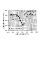
実施例3の各条件で熱処理したレール鋼を用いて、足部裏面の温度測定位置の5mm深さ点における硬度(Hv98N)を測定した。測定結果を図5に示す。
図5に示されるように、加熱温度が600℃超725℃(Ac1点)以下の場合には、冷却を放冷及び加速冷却のいずれの方法で行っても、測定位置の硬度は、十分に低下することがわかる。
加熱温度が725℃(Ac1点)超800℃以下の場合は、加熱後に放冷により冷却すると、測定位置の硬度が十分に低下する。一方、加熱温度が725℃(Ac1点)超800℃以下の場合は、加熱後に加速冷却により冷却すると、測定位置の硬度が十分に低下しない。
なお、以下の実施例4に示されるように、725℃超800℃以下で加熱した後に加速冷却した場合も、脆性破壊に対する耐性は向上する。
レール鋼の溶接部を以下の条件で熱処理した。
・加熱領域:足部裏面(実施例)又は足部裏面と頭部との両方(比較例)
・初期温度:400℃
・加熱温度:750℃
・加熱速度:5℃/秒
・加熱後の保定:無し
・加熱後の冷却速度:5℃/秒(加速冷却)及び0.9℃/秒(放冷)のそれぞれで行った。
・コイルの外のり領域の横方向長さL1:Lhの1.2倍
・コイルの外のり領域の縦方向長さL2:Wの1.4倍((L2-W)/2=Wの0.2倍)
実施例4で熱処理した各レール鋼及び熱処理を施さない溶接後の状態の試験材(AW)における評価を、評価1と同様の方法で行った。測定結果を図6に示す。
図6に示されるように、足部のみを750℃で加熱した実施例においては、加熱後に加速冷却及び放冷のいずれの方法で冷却を行った場合であっても、破断までの回数が、AWに比べて大幅に増加した。なお、加熱後に放冷により冷却した場合には、加熱後に加速冷却により冷却した場合に比べて、破断までの回数が増加していた。
レール鋼の溶接部を以下の条件で熱処理した。
・加熱領域:足部裏面
・初期温度:400℃
・加熱温度:750℃
・加熱速度:0.2℃/秒~25℃/秒の範囲で変化させた。
・加熱後の保定:無し
・加熱後の冷却速度:0.9℃/秒(放冷)
・コイルの外のり領域の横方向長さL1:Lhの1.2倍
・コイルの外のり領域の縦方向長さL2:Wの1.4倍((L2-W)/2=Wの0.2倍)
実施例5で熱処理した各レール鋼における評価を、評価2と同様の方法で行った。測定結果を図7に示す。
図7に示されるように、加熱速度を高めると破断荷重が増加し、脆性破壊に対する耐性が高まる傾向にある。加熱速度が3℃/秒未満の場合は、破断たわみが極端に大きくなるとともに、破断荷重が低下していた。加熱速度が20℃/秒を超える場合は、加熱速度が20℃/秒の場合と比べて、破断たわみ及び破断荷重は変化せず、亀裂の進行を抑制する効果が飽和する。
レール鋼の溶接部を以下の条件で熱処理した。
・加熱領域:足部裏面
・初期温度:400℃
・加熱温度:650℃
・加熱速度:5℃/秒
・加熱後の保定:無し
・加熱後の冷却速度:5℃/秒(加速冷却)
・コイルの外のり領域の横方向長さL1:Lhの1.2倍(実施例)又はLhの1.0倍(比較例)
・コイルの外のり領域の縦方向長さL2:Wの1.4倍((L2-W)/2=Wの0.2倍)
実施例6で熱処理した各レール鋼及び熱処理を施さない溶接後の状態の試験材(AW)を用いて、足部裏面の温度測定位置の5mm深さ点における硬度(Hv98N)を測定した。測定結果を図8に示す。
図8に示されるように、AWでは、HAZにおける最も硬い部分は、溶接中心面上の位置である。また、AWの測定結果から、硬度が急激に変化する部分が、HAZの外側の位置(溶接中心面から25~30mmの位置であり、Lhが40mmの場合にはLhの約0.7倍の位置)に存在することが分かる。
L1の長さがLhの1.0倍であるコイルを用いて、HAZと同じ範囲を加熱した場合、溶接中心面は軟化するが、硬度が急激に変化する部分の硬度はほとんど変わらない。
一方、L1の長さがLhの1.2倍であるコイルを用いて加熱した場合は、溶接中心面が軟化するとともに、硬度が急激に変化する部分の硬度変化が緩やかになっていることが分かる。
レール鋼の溶接部を以下の条件で熱処理した。
・加熱領域:足部裏面
・初期温度:400℃
・加熱温度:650℃
・加熱速度:5℃/秒
・加熱後の保定:無し
・加熱後の冷却速度:5℃/秒(加速冷却)
・コイルの外のり領域の横方向長さL1:Lhの0.8倍~3.0倍の範囲で変化させた。なお、L1がLhの1.2倍以上である場合は実施例であり、その他は比較例である。
・コイルの外のり領域の縦方向長さL2:Wの1.4倍((L2-W)/2=Wの0.2倍)
実施例7で熱処理した各レール鋼における評価を、評価2と同様の方法で行った。測定結果を図9に示す。
図9に示されるように、L1をLhの1.2倍以上とすることで、破断たわみが顕著に大きくなり、脆性破壊に対する耐性が高まることがわかる。これは、HAZの外側に位置する、硬度が急激に変化する部分が軟化されたことによる効果であると考えられる。
レール鋼の溶接部を以下の条件で熱処理した。
・加熱領域:足部裏面
・初期温度:400℃
・加熱温度(溶接中心面上かつレール幅方向中央の点):600℃
・加熱速度:5℃/秒
・加熱後の保定:無し
・コイルの外のり領域の横方向長さL1:Lhの1.2倍
・コイルの外のり領域の縦方向長さL2:Wの1.0倍((L2-W)/2=0、比較例)、Wの1.1倍((L2-W)/2=Wの0.05倍、実施例)及びWの1.2倍((L2-W)/2=Wの0.1倍、実施例)の3種類で行った。
実施例8において熱処理した直後、すなわち溶接中心面上かつレール幅方向中央の点の温度が600℃となったときの、位置Aの温度及び位置Bの温度をレール長さ方向に沿って測定した。ここで、位置Aは、レールの幅方向の一端及び他端から内側に5mmの位置であり、位置Bは、レールの幅方向中央である。
なお、レールの幅方向の一端から内側に5mmの位置の温度と、他端から内側に5mmの位置の温度とは等しかった。
測定結果を図10A~図10Cに示す。
図10Aに示されるように、L2が、Wの1.0倍の場合には、位置Bを600℃に加熱すると、位置Aの温度は、800℃を超える。この場合には、図5等に示されるように、溶接中心面上の位置Aは、十分に軟化されない。
図10Bに示されるように、L2がWの1.1倍である場合((L2-W)/2が、Wの0.05倍)の場合には、位置Bを600℃に加熱すると、位置Aの温度を800℃以下に抑えることができる。これにより、位置Aを軟化させることができる。しかし、位置Aの温度は、Ac1点(725℃)を超えているため、軟化させるためには、加熱後に放冷により冷却することが必要である。
図10Cに示されるように、L2がWの1.2倍((L2-W)/2が、Wの0.1倍)の場合には、位置Bを600℃に加熱すると、位置Aの温度をAc1点(725℃)以下に抑えることができる。これにより、加熱後に、放冷及び加速冷却のいずれの方法を用いて冷却しても、軟化が可能である。
11:溶接部
12:溶接中心面
13:頭部
14:足部
15:柱部
16:一対の仮想線で挟まれる領域
17:HAZ
18:レールの幅方向の中心位置
20:熱処理装置
21:コイル
22:外のり領域
23:軸
24:仮想線
30:溶接部
31:円筒鋼材
32:レール鋼
33:車輪
34:溶接部
35:円筒鋼材
36:レール鋼
37:円筒鋼材
C :足部裏面の溶接中心面上かつレール鋼の幅方向の中心位置上にある位置
Claims (9)
- コイルを有し、レール鋼の溶接部の足部裏面を誘導加熱により加熱する熱処理装置であって、
前記溶接部において溶接時にAc1点以上に加熱された領域をHAZ、前記足部裏面におけるレール長さ方向の前記HAZの長さをLh、前記レール鋼の幅をWとし、
前記足部裏面を対向する視線で見た場合に、前記コイルの外のり領域の前記レール長さ方向の長さが前記Lhの1.2倍以上であり、前記コイルの前記外のり領域の前記レールの幅方向の長さが前記Wの1.1倍以上である
ことを特徴とする熱処理装置。 - 前記コイルの前記外のり領域の、前記レール長さ方向の前記長さが、40mm以上である
ことを特徴とする請求項1に記載の熱処理装置。 - 前記コイルの前記外のり領域の、前記レール幅方向の前記長さが、前記Wの1.2倍以上である
ことを特徴とする請求項1又は請求項2に記載の熱処理装置。 - 前記コイルの前記外のり領域の形状が長方形である
ことを特徴とする請求項1から請求項3の何れか1項に記載の熱処理装置。 - レール鋼の溶接部の熱処理方法であって、
請求項1から請求項4の何れか1項に記載の熱処理装置の前記コイルを前記足部裏面に対向配置して、前記足部裏面に対向する視線で見た場合に溶接中心面から対称の位置にあり相互の距離が前記Lhの1.2倍である一対の仮想線で挟まれる領域を、3℃/秒以上20℃/秒以下の加熱速度で加熱することにより、少なくとも前記足部裏面の前記溶接中心面上かつ前記レール鋼の幅方向の中心上にある位置Cを600℃超800℃以下に加熱する加熱工程と;
前記加熱工程後に、前記レール鋼を冷却する冷却工程と;
を有することを特徴とするレール鋼の溶接部の熱処理方法。 - 前記加熱工程において、前記位置Cを、600℃超Ac1点以下の温度に加熱する
ことを特徴とする請求項5に記載のレール鋼の溶接部の熱処理方法。 - 前記加熱工程において、前記位置Cを、Ac1点超800℃以下の温度に加熱し、
前記冷却工程を、放冷により行う
ことを特徴とする請求項5に記載のレール鋼の溶接部の熱処理方法。 - 前記加熱工程において、前記レール鋼の頭部の加熱温度を600℃以下とする
ことを特徴とする請求項5から請求項7の何れか1項に記載のレール鋼の溶接部の熱処理方法。 - 溶接部を有するレール鋼であって、
前記溶接部に請求項5から請求項8の何れか1項に記載のレール鋼の溶接部の熱処理方法によって熱処理が施されている
ことを特徴とするレール鋼。
Priority Applications (5)
| Application Number | Priority Date | Filing Date | Title |
|---|---|---|---|
| US15/123,485 US10544479B2 (en) | 2014-04-08 | 2015-04-06 | Heat treatment device, heat treatment method, and rail steel |
| JP2016512706A JP6210151B2 (ja) | 2014-04-08 | 2015-04-06 | 熱処理装置及び熱処理方法 |
| AU2015244882A AU2015244882B2 (en) | 2014-04-08 | 2015-04-06 | Heat treatment device, heat treatment method, and rail steel |
| CA2941217A CA2941217C (en) | 2014-04-08 | 2015-04-06 | Heat treatment device, heat treatment method, and rail steel |
| RU2016138533A RU2661199C2 (ru) | 2014-04-08 | 2015-04-06 | Устройство для термической обработки, способ термической обработки и рельсовая сталь |
Applications Claiming Priority (4)
| Application Number | Priority Date | Filing Date | Title |
|---|---|---|---|
| JP2014079489 | 2014-04-08 | ||
| JP2014-079503 | 2014-04-08 | ||
| JP2014079503 | 2014-04-08 | ||
| JP2014-079489 | 2014-04-08 |
Publications (1)
| Publication Number | Publication Date |
|---|---|
| WO2015156243A1 true WO2015156243A1 (ja) | 2015-10-15 |
Family
ID=54287819
Family Applications (1)
| Application Number | Title | Priority Date | Filing Date |
|---|---|---|---|
| PCT/JP2015/060713 Ceased WO2015156243A1 (ja) | 2014-04-08 | 2015-04-06 | 熱処理装置、熱処理方法及びレール鋼 |
Country Status (6)
| Country | Link |
|---|---|
| US (1) | US10544479B2 (ja) |
| JP (1) | JP6210151B2 (ja) |
| AU (1) | AU2015244882B2 (ja) |
| CA (1) | CA2941217C (ja) |
| RU (1) | RU2661199C2 (ja) |
| WO (1) | WO2015156243A1 (ja) |
Cited By (1)
| Publication number | Priority date | Publication date | Assignee | Title |
|---|---|---|---|---|
| CN106834660A (zh) * | 2015-12-03 | 2017-06-13 | 上海工程技术大学 | 一种线路钢轨焊接接头中频淬火控制方法 |
Families Citing this family (9)
| Publication number | Priority date | Publication date | Assignee | Title |
|---|---|---|---|---|
| CA2941217C (en) * | 2014-04-08 | 2018-10-30 | Nippon Steel & Sumitomo Metal Corporation | Heat treatment device, heat treatment method, and rail steel |
| BR112019015220B1 (pt) | 2017-09-29 | 2023-10-03 | CF&I Steel L.P. D/B/A EVRAZ Rocky Mountain Steel | Método para unir trilhos de aço com entrada de calor por solda controlada |
| CN108085469B (zh) * | 2018-02-12 | 2023-05-23 | 辽宁科技大学 | 一种提供高速、均匀钢轨风冷淬火风源的装置 |
| CN108457142B (zh) * | 2018-03-01 | 2024-05-14 | 中国铁道科学研究院集团有限公司金属及化学研究所 | 一种槽型钢轨预热和焊补一体化设备 |
| CN108977647B (zh) * | 2018-09-27 | 2023-09-22 | 中国电建集团山东电力建设第一工程有限公司 | 锅炉受热面销钉焊后热处理专用工装及热处理方法 |
| RU2704051C1 (ru) * | 2018-10-23 | 2019-10-23 | Государственный научный центр Российской Федерации - федеральное государственное унитарное предприятие "Исследовательский Центр имени М.В. Келдыша" | Способ и установка для поверхностного упрочнения головок стальных рельсов действующих путей |
| RU2755713C1 (ru) * | 2020-06-05 | 2021-09-20 | Общество с ограниченной ответственностью "Информационные технологии" (ООО "ИнфоТех") | Устройство и способ термической обработки длинномерного изделия г-образного профиля, имеющего подошву, шейку, головку |
| CN112375891A (zh) * | 2020-10-20 | 2021-02-19 | 包头钢铁(集团)有限责任公司 | 一种消除贝氏体钢轨拉伸断口脆性平台的在线回火工艺 |
| CN113736976B (zh) * | 2021-09-01 | 2025-03-28 | 中铁宝桥集团有限公司 | 一种钢轨跟端加热装置 |
Citations (6)
| Publication number | Priority date | Publication date | Assignee | Title |
|---|---|---|---|---|
| JPS6167719A (ja) * | 1984-09-11 | 1986-04-07 | Nippon Kokan Kk <Nkk> | レール継目溶接部熱処理装置 |
| JPS6345321A (ja) * | 1986-08-11 | 1988-02-26 | Daiwa Kogyo Kk | レ−ルの高周波誘導加熱方法 |
| JP2001105158A (ja) * | 1999-10-13 | 2001-04-17 | Daido Steel Co Ltd | 鉄道レール拡散接合用誘導加熱コイル、およびそれを用いた鉄道レールの拡散接合方法 |
| WO2010116680A1 (ja) * | 2009-03-30 | 2010-10-14 | 新日本製鐵株式会社 | レール溶接部の冷却方法、レール溶接部の冷却装置、及びレール溶接継手 |
| JP2012030242A (ja) * | 2010-07-29 | 2012-02-16 | Nippon Steel Corp | レールの溶接部の後熱処理方法 |
| WO2012161207A1 (ja) * | 2011-05-25 | 2012-11-29 | 新日鐵住金株式会社 | レール溶接部の再加熱方法 |
Family Cites Families (21)
| Publication number | Priority date | Publication date | Assignee | Title |
|---|---|---|---|---|
| GB273326A (en) | 1926-06-28 | 1928-05-24 | Curt Stedefeld | Improvements in the heat treatment of welded rail joints |
| DE2208692C3 (de) | 1972-02-24 | 1974-12-12 | Elektro-Thermit Gmbh, 4300 Essen | Verfahren zur Herstellung aluminothermischerSchienenverbindungssch weißungen |
| JPS5933072B2 (ja) | 1980-03-27 | 1984-08-13 | 日本鋼管株式会社 | レ−ル圧接のためのレ−ルクランプ装置 |
| JPS58153731A (ja) | 1982-03-05 | 1983-09-12 | Hitachi Ltd | 溶接残留応力の低減方法 |
| JPS5993837A (ja) | 1982-11-19 | 1984-05-30 | Nippon Steel Corp | レ−ル溶接部の耐疲労破壊特性向上法 |
| JPS5993838A (ja) | 1982-11-19 | 1984-05-30 | Nippon Steel Corp | レ−ル溶接部の耐破壊特性向上法 |
| JPS6033313A (ja) | 1983-08-05 | 1985-02-20 | Nippon Kokan Kk <Nkk> | レ−ル溶接部の冷却装置 |
| JPS63160799A (ja) | 1986-12-24 | 1988-07-04 | Nippon Steel Corp | レ−ル用被覆ア−ク溶接棒 |
| SU1735392A1 (ru) | 1989-12-13 | 1992-05-23 | Всесоюзный Научно-Исследовательский Институт Железнодорожного Транспорта | Способ термической обработки сварных рельсов |
| JPH03249127A (ja) | 1990-02-28 | 1991-11-07 | Nippon Steel Corp | レール溶接継手部のショットピーニング処理方法 |
| JPH03277720A (ja) | 1990-03-27 | 1991-12-09 | Nippon Steel Corp | レール突合せ溶接部の耐疲労破壊特性向上法 |
| JPH08337819A (ja) | 1995-06-08 | 1996-12-24 | Nippon Steel Corp | レール溶接部の耐腹部水平き裂性改善法 |
| JPH1158042A (ja) | 1997-08-27 | 1999-03-02 | Nippon Steel Corp | ベイナイト鋼レールのテルミット溶接方法 |
| JP3537661B2 (ja) | 1998-03-25 | 2004-06-14 | 財団法人鉄道総合技術研究所 | レールガス圧接用ガスバーナ |
| GB2403174B (en) | 2003-06-26 | 2006-11-15 | Corus Uk Ltd | Steel rails |
| JP2006057128A (ja) | 2004-08-18 | 2006-03-02 | Nippon Steel Corp | 耐落重破壊特性に優れたパーライト系レールの製造方法 |
| RU2411295C2 (ru) | 2008-12-18 | 2011-02-10 | Рейлтек Интернейшнел | Способ и устройство термообработки рельсового стыка |
| JP2010000543A (ja) | 2009-10-02 | 2010-01-07 | Toshiba Corp | 応力腐食割れ発生抑制方法 |
| IN2012DN03791A (ja) | 2009-10-30 | 2015-08-28 | Nippon Steel & Sumitomo Metal Corp | |
| CA2880953C (en) * | 2012-11-16 | 2017-10-10 | Nippon Steel & Sumitomo Metal Corporation | Stress-relief heat treatment apparatus comprising induction heating coils |
| CA2941217C (en) * | 2014-04-08 | 2018-10-30 | Nippon Steel & Sumitomo Metal Corporation | Heat treatment device, heat treatment method, and rail steel |
-
2015
- 2015-04-06 CA CA2941217A patent/CA2941217C/en not_active Expired - Fee Related
- 2015-04-06 AU AU2015244882A patent/AU2015244882B2/en not_active Ceased
- 2015-04-06 RU RU2016138533A patent/RU2661199C2/ru not_active IP Right Cessation
- 2015-04-06 JP JP2016512706A patent/JP6210151B2/ja active Active
- 2015-04-06 US US15/123,485 patent/US10544479B2/en not_active Expired - Fee Related
- 2015-04-06 WO PCT/JP2015/060713 patent/WO2015156243A1/ja not_active Ceased
Patent Citations (6)
| Publication number | Priority date | Publication date | Assignee | Title |
|---|---|---|---|---|
| JPS6167719A (ja) * | 1984-09-11 | 1986-04-07 | Nippon Kokan Kk <Nkk> | レール継目溶接部熱処理装置 |
| JPS6345321A (ja) * | 1986-08-11 | 1988-02-26 | Daiwa Kogyo Kk | レ−ルの高周波誘導加熱方法 |
| JP2001105158A (ja) * | 1999-10-13 | 2001-04-17 | Daido Steel Co Ltd | 鉄道レール拡散接合用誘導加熱コイル、およびそれを用いた鉄道レールの拡散接合方法 |
| WO2010116680A1 (ja) * | 2009-03-30 | 2010-10-14 | 新日本製鐵株式会社 | レール溶接部の冷却方法、レール溶接部の冷却装置、及びレール溶接継手 |
| JP2012030242A (ja) * | 2010-07-29 | 2012-02-16 | Nippon Steel Corp | レールの溶接部の後熱処理方法 |
| WO2012161207A1 (ja) * | 2011-05-25 | 2012-11-29 | 新日鐵住金株式会社 | レール溶接部の再加熱方法 |
Cited By (2)
| Publication number | Priority date | Publication date | Assignee | Title |
|---|---|---|---|---|
| CN106834660A (zh) * | 2015-12-03 | 2017-06-13 | 上海工程技术大学 | 一种线路钢轨焊接接头中频淬火控制方法 |
| CN106834660B (zh) * | 2015-12-03 | 2018-09-18 | 上海工程技术大学 | 一种线路钢轨焊接接头中频淬火控制方法 |
Also Published As
| Publication number | Publication date |
|---|---|
| CA2941217A1 (en) | 2015-10-15 |
| RU2016138533A3 (ja) | 2018-05-11 |
| JPWO2015156243A1 (ja) | 2017-04-13 |
| RU2661199C2 (ru) | 2018-07-16 |
| JP6210151B2 (ja) | 2017-10-11 |
| US10544479B2 (en) | 2020-01-28 |
| AU2015244882B2 (en) | 2017-07-27 |
| AU2015244882A1 (en) | 2016-09-08 |
| US20170073793A1 (en) | 2017-03-16 |
| CA2941217C (en) | 2018-10-30 |
| RU2016138533A (ru) | 2018-05-11 |
Similar Documents
| Publication | Publication Date | Title |
|---|---|---|
| JP6210151B2 (ja) | 熱処理装置及び熱処理方法 | |
| KR102020927B1 (ko) | 필릿 아크 용접 조인트 및 그 제조 방법 | |
| US20190100822A1 (en) | Method for joining steel rails with controlled weld heat input | |
| CN105177273B (zh) | 一种提高关键重要构件疲劳强度的激光冲击强化方法 | |
| WO2014077140A1 (ja) | 後熱処理装置 | |
| JP5549782B2 (ja) | レール溶接部の再加熱方法 | |
| WO2014015702A1 (zh) | 一种马氏体耐热钢的焊接工艺 | |
| JPS6299438A (ja) | 不安定破壊伝播停止能力を有する耐摩耗性高性能レ−ル | |
| JP6587993B2 (ja) | ばね用鋼線およびその製造方法 | |
| JP2010188382A (ja) | レールの溶接部の冷却方法 | |
| JP4994928B2 (ja) | 耐折損性に優れたレールの製造方法 | |
| JP6265267B2 (ja) | 熱処理レールの製造方法および製造装置 | |
| JP2014101534A (ja) | 後熱処理装置 | |
| JP6390677B2 (ja) | 低炭素マルテンサイト系ステンレス鋼溶接管およびその製造方法 | |
| JP5534492B2 (ja) | 炭素工具鋼鋼帯の製造方法 | |
| JP2016074004A (ja) | 電縫溶接部の中温域のクリープ特性に優れた高強度電縫鋼管の製造方法 | |
| JP5477452B1 (ja) | 後熱処理装置 | |
| JP5233388B2 (ja) | 電縫管溶接部の熱処理装置 | |
| JP5573325B2 (ja) | 鋼管の連続熱処理方法 | |
| RU2484149C1 (ru) | Способ термической обработки сварных труб | |
| KR100761730B1 (ko) | 전기저항 용접강관의 열처리 방법 | |
| KR101456216B1 (ko) | 고주파 열처리 장치에 적용되는 고주파 열처리용 트랙 링크 코일 장치 | |
| JP5964256B2 (ja) | 二相系ステンレス鋼製構造物製造方法および熱処理装置 | |
| CN103862148A (zh) | 纳米贝氏体钢奥氏体晶粒细化加速再纳米化的方法 | |
| JP5749916B2 (ja) | 熱処理筒状金属部材及びその熱処理筒状金属部材の製造方法 |
Legal Events
| Date | Code | Title | Description |
|---|---|---|---|
| 121 | Ep: the epo has been informed by wipo that ep was designated in this application |
Ref document number: 15776601 Country of ref document: EP Kind code of ref document: A1 |
|
| ENP | Entry into the national phase |
Ref document number: 2016512706 Country of ref document: JP Kind code of ref document: A |
|
| ENP | Entry into the national phase |
Ref document number: 2941217 Country of ref document: CA |
|
| WWE | Wipo information: entry into national phase |
Ref document number: 15123485 Country of ref document: US |
|
| ENP | Entry into the national phase |
Ref document number: 2015244882 Country of ref document: AU Date of ref document: 20150406 Kind code of ref document: A |
|
| NENP | Non-entry into the national phase |
Ref country code: DE |
|
| REG | Reference to national code |
Ref country code: BR Ref legal event code: B01A Ref document number: 112016021901 Country of ref document: BR |
|
| ENP | Entry into the national phase |
Ref document number: 2016138533 Country of ref document: RU Kind code of ref document: A |
|
| 122 | Ep: pct application non-entry in european phase |
Ref document number: 15776601 Country of ref document: EP Kind code of ref document: A1 |
|
| ENP | Entry into the national phase |
Ref document number: 112016021901 Country of ref document: BR Kind code of ref document: A2 Effective date: 20160923 |