WO2015147200A1 - 車両操舵システム用ユニット - Google Patents
車両操舵システム用ユニット Download PDFInfo
- Publication number
- WO2015147200A1 WO2015147200A1 PCT/JP2015/059452 JP2015059452W WO2015147200A1 WO 2015147200 A1 WO2015147200 A1 WO 2015147200A1 JP 2015059452 W JP2015059452 W JP 2015059452W WO 2015147200 A1 WO2015147200 A1 WO 2015147200A1
- Authority
- WO
- WIPO (PCT)
- Prior art keywords
- shaft
- clutch
- pinion
- reaction force
- vehicle steering
- Prior art date
Links
Images


Classifications
-
- B—PERFORMING OPERATIONS; TRANSPORTING
- B62—LAND VEHICLES FOR TRAVELLING OTHERWISE THAN ON RAILS
- B62D—MOTOR VEHICLES; TRAILERS
- B62D5/00—Power-assisted or power-driven steering
- B62D5/001—Mechanical components or aspects of steer-by-wire systems, not otherwise provided for in this maingroup
-
- B—PERFORMING OPERATIONS; TRANSPORTING
- B62—LAND VEHICLES FOR TRAVELLING OTHERWISE THAN ON RAILS
- B62D—MOTOR VEHICLES; TRAILERS
- B62D1/00—Steering controls, i.e. means for initiating a change of direction of the vehicle
- B62D1/02—Steering controls, i.e. means for initiating a change of direction of the vehicle vehicle-mounted
- B62D1/16—Steering columns
- B62D1/20—Connecting steering column to steering gear
-
- B—PERFORMING OPERATIONS; TRANSPORTING
- B62—LAND VEHICLES FOR TRAVELLING OTHERWISE THAN ON RAILS
- B62D—MOTOR VEHICLES; TRAILERS
- B62D5/00—Power-assisted or power-driven steering
- B62D5/001—Mechanical components or aspects of steer-by-wire systems, not otherwise provided for in this maingroup
- B62D5/003—Backup systems, e.g. for manual steering
-
- B—PERFORMING OPERATIONS; TRANSPORTING
- B62—LAND VEHICLES FOR TRAVELLING OTHERWISE THAN ON RAILS
- B62D—MOTOR VEHICLES; TRAILERS
- B62D5/00—Power-assisted or power-driven steering
- B62D5/04—Power-assisted or power-driven steering electrical, e.g. using an electric servo-motor connected to, or forming part of, the steering gear
- B62D5/0403—Power-assisted or power-driven steering electrical, e.g. using an electric servo-motor connected to, or forming part of, the steering gear characterised by constructional features, e.g. common housing for motor and gear box
-
- B—PERFORMING OPERATIONS; TRANSPORTING
- B62—LAND VEHICLES FOR TRAVELLING OTHERWISE THAN ON RAILS
- B62D—MOTOR VEHICLES; TRAILERS
- B62D3/00—Steering gears
- B62D3/02—Steering gears mechanical
- B62D3/12—Steering gears mechanical of rack-and-pinion type
Definitions
- This invention relates to a vehicle steering system unit for constructing a route for transmitting rotation from a steering wheel to a rack and pinion.
- steer-by-wire steering systems have been developed for automobiles.
- the steering wheel of a vehicle and the rack and pinion pinion are not mechanically connected via a clutch, and the steering angle of the steering wheel is replaced with an electrical signal, and the controller is based on the electrical signal.
- the steering angle of the steering wheel is controlled by driving the steering actuator, and the controller controls the reaction force motor to apply an appropriate steering reaction force to the steering wheel.
- the steering wheel and pinion are connected by a clutch so that the steering wheel can be directly steered (for example, Patent Documents 1 and 2 below). ).
- JP 2005-262969 A Japanese Patent No. 3180505 Japanese Patent No. 4252392
- An abnormal rotation transmission path is constructed by a universal joint 107 that connects the input shaft 105 and a universal joint 108 that connects the second shaft 103 and the output shaft 106 of the clutch 104.
- a radial load is generated in accordance with the rotation transmission having the operation angle between the first shaft 101 and the input shaft 105 and the rotation transmission having the operation angle between the second shaft 103 and the output shaft 106, and is intermediate between the universal joints 107 and 108.
- the load is applied to the input shaft 105 and the output shaft 106 through the shafts 109 and 110. For this reason, there is room for improvement in that it is difficult to center the input shaft 105 and the output shaft 106, which are important for stable operation of the clutch 104.
- the problem to be solved by the present invention is to make it easier to stably operate a clutch incorporated between a steering wheel and a pinion of a vehicle steering system.
- the present invention provides a first shaft coupled to a steering wheel or a second shaft coupled to a rack and pinion pinion, and rotation transmission between the first shaft and the second shaft.
- a vehicle steering system unit in which the clutch input shaft and the first shaft, or the clutch output shaft and the second shaft are fixed concentrically.
- the present invention can eliminate the radial load on one of the output shaft and the input shaft of the clutch and facilitate the stable operation of the clutch.
- a vehicle steering system unit according to a first embodiment of the present invention will be described with reference to FIGS.
- the steering wheel 1 of the automobile and the pinion 3 of the rack and pinion 2 are not mechanically connected via the clutch 4, and the steering angle of the steering wheel 1 is replaced with an electrical signal.
- the steering angle of the steering wheel 5 is automatically controlled by an electric steering actuator (not shown), and the reaction force motor 6 is automatically controlled to give an appropriate steering reaction force to the steering wheel 1.
- the reaction force motor 6 or the like, the steering wheel 1 and the pinion 3 are connected by the clutch 4 and the steering wheel 1 can be directly steered.
- the first shaft 7 is connected to the steering wheel 1.
- the reaction force motor 6 applies a steering reaction force to the first shaft 7.
- the first shaft 7 is provided integrally with the output shaft of the reaction force motor 6. For this reason, the reaction force motor 6 can directly apply a steering reaction force to the first shaft 7.
- the housing of the reaction force motor 6 is attached to a partition wall that partitions the engine room and the cab of the vehicle body.
- the rack and pinion 2 includes a rack 8 and a pinion 3 that meshes with the rack 8.
- a second shaft 9 is connected to the pinion 3.
- the rack 8 is driven by an electric steering actuator.
- the clutch 4 includes a mechanical clutch portion and clutch switching means for switching a connected state or a disconnected state of the mechanical clutch portion.
- the mechanical clutch unit includes an input shaft 10, an output shaft 11, an engagement surface 12 that rotates integrally with the input shaft 10, an engagement surface 13 that rotates integrally with the output shaft 11, and engagement surfaces 12, 13. And an engaging member 14 that fits in a wedge space formed by the above.
- the clutch switching means is controlled by a control device (not shown) of the vehicle steering system. When the clutch switching means engages the engagement element 14 with the engagement surface 12 and the engagement surface 13, the clutch 4 is in a connected state, and when the engagement is released, the clutch 4 is in a non-connected state.
- a clutch 4 what was disclosed by patent document 1 and patent document 3, for example is employable.
- the input shaft 10 of the clutch 4 is a member to which torque is always input from the steering wheel 1 side.
- the output shaft 11 of the clutch 4 is a member that outputs torque from the steering wheel 1 to the pinion 3 side in the connected state.
- the input shaft 10 of the clutch 4 and the first shaft 7 are connected by a universal joint 15.
- the universal joint 15 may be a constant velocity joint that can transmit rotation from the first shaft 7 to the input shaft 10 with a required operating angle.
- a double cardan joint can be adopted as the universal joint 15.
- the output shaft 11 of the clutch 4 and the second shaft 9 are integrally provided.
- “provided integrally” means that the output shaft 11 and the second shaft 9 are formed in the same component.
- the housing 16 of the rack and pinion 2 and the housing 17 of the clutch 4 are integrated.
- integrated means that a space surrounding the rack and pinion 2, a space surrounding the clutch 4, and a hole through which the output shaft 11 and the second shaft 9 pass are a series of spaces.
- the output shaft 11 is supported on the inner periphery of the housing 17 via a bearing.
- the first embodiment can eliminate the radial load on the output shaft 11 of the clutch 4 and facilitate the clutch 4 to operate more stably. If the universal joint is eliminated on the output shaft 11 side, the axial distance between the rack and pinion 2 and the clutch 4 can be made shorter than before, and the housing can be easily integrated. Can do.
- the housing 16 of the rack and pinion 2 and the housing 17 of the clutch 4 are separated. Even if it is a separate body, the output shaft 11 and the second shaft 9 are integrally provided, so that the concentric fixation of the input shaft 11 and the second shaft 9 is not affected.
- the housing 17 of the clutch 4 is attached to a partition wall that partitions the engine room and the cab of the vehicle body.
- connection means 30 only needs to be able to transmit rotation that is concentrically fixed, and examples thereof include serrations, splines, and flanges.
- the output shaft 11 of the clutch 4 and the second shaft 9 are connected by a universal joint 41.
- the universal joint 41 is composed of a constant velocity joint capable of transmitting rotation from the output shaft 11 to the second shaft 9 with a required operating angle.
- the clutch input shaft 10 and the first shaft 7 are integrally provided.
- the fourth embodiment since the input shaft 10 of the clutch 4 and the first shaft 7 are integrally provided, the input shaft 10 and the first shaft 7 are always fixed concentrically. For this reason, the rotation transmission path between the steering wheel 1 and the pinion 3 does not have a universal joint for connecting the input shaft 10 and the first shaft 7, and is constructed only by using the universal joint 41 only on the output shaft 11 side. . Therefore, the fourth embodiment can eliminate the radial load on the input shaft 10 of the clutch 4 and facilitate the clutch 4 to operate more stably. If the universal joint is eliminated on the input shaft 10 side, as a result, the axial distance between the steering wheel 1 and the clutch 4 can be made shorter than before, and the housing can be easily integrated. it can.
- the fifth embodiment is a further modification of the fourth embodiment, only differences from the fourth embodiment will be described here.
- the input shaft 10 of the clutch 4 and the first shaft 7 are concentrically fixed by the connecting means 50.
- the connecting means 50 only needs to be able to transmit rotation that is concentrically fixed.
- the sixth embodiment will be described with reference to FIG. Since the sixth embodiment is a further modification of the fourth embodiment, only differences from the fourth embodiment will be described here.
- the output shaft 61 of the reaction force motor 6 and the first shaft 7 are provided separately.
- a drive pulley 62 is provided on the output shaft 61.
- a driven pulley 63 is provided on the first shaft 7.
- a transmission belt 64 is wound around the driven pulley 63 and the driving pulley 62.
- the steering reaction force generated by the reaction force motor 6 is applied to the first shaft 7 via the drive pulley 62, the transmission belt 64, and the driven pulley 63.
- a steering reaction force applying means using such a reaction force motor 6 for example, one disclosed in Patent Document 2 can be adopted.
Landscapes
- Engineering & Computer Science (AREA)
- Chemical & Material Sciences (AREA)
- Combustion & Propulsion (AREA)
- Transportation (AREA)
- Mechanical Engineering (AREA)
- Power Steering Mechanism (AREA)
Abstract
車両操舵システムのステアリングホイール及びピニオン間に組込むクラッチをより安定作動させ易くすることを課題とする。ステアリングホイール(1)に連結された第1軸(7)、又はラックアンドピニオン(2)のピニオン(3)に連結された第2軸(9)と、第1軸(7)及び第2軸(9)間の回転伝達経路に組込まれるクラッチ(4)と、を備え、クラッチ(4)の入力軸(10)と第1軸(7)、又はクラッチ(4)の出力軸(11)と第2軸(9)が、同心に固定されている車両操舵システム用ユニットに構成した。
Description
この発明は、ステアリングホイールからラックアンドピニオンへ回転を伝達する経路を構築するための車両操舵システム用ユニットに関する。
近年、ステアバイワイヤ方式の操舵システムが自動車用に開発されている。ステアバイワイヤ方式では、通常、自動車のステアリングホイールとラックアンドピニオンのピニオンがクラッチを介して機械的に連結されておらず、ステアリングホイールの舵角を電気信号に置き換え、その電気信号に基づいてコントローラが操舵アクチュエータを駆動させることにより操舵車輪の操舵角度を制御すると共に、コントローラが反力モータの制御を行ってステアリングホイールに適切な操舵反力を与えるようになっている。万一、操舵アクチュエータや反力モータ等に異常が生じた場合、クラッチによってステアリングホイールとピニオンが連結され、ステアリングホイールで直接操舵することができるようになっている(例えば、下記特許文献1、2)。
ステアバイワイヤ方式に好適なクラッチとして、ローラクラッチを電磁的に切り替えるものがある(例えば、下記特許文献3)。
しかしながら、従来は、図8に示すように、ステアリングホイール100に連結された第1軸101、ラックアンドピニオンのピニオン102に連結された第2軸103、クラッチ104、第1軸101とクラッチ104の入力軸105を連結する自在継手107、第2軸103とクラッチ104の出力軸106を連結する自在継手108によって異常時用の回転伝達経路が構築されている。第1軸101と入力軸105間の作動角をもった回転伝達、第2軸103と出力軸106間の作動角をもった回転伝達に伴ってラジアル荷重が生じ、自在継手107、108の中間軸109、110を介して入力軸105、出力軸106に負荷される。このため、クラッチ104の安定作動に重要な入力軸105、出力軸106の芯出しが難しい点で改良の余地がある。
上述の背景に鑑み、この発明が解決しようとする課題は、車両操舵システムのステアリングホイール及びピニオン間に組込むクラッチをより安定作動させ易くすることである。
上記の課題を達成するため、この発明は、ステアリングホイールに連結された第1軸、又はラックアンドピニオンのピニオンに連結された第2軸と、前記第1軸及び前記第2軸間の回転伝達経路に組込まれるクラッチと、を備え、前記クラッチの入力軸と前記第1軸、又は前記クラッチの出力軸と前記第2軸が、同心に固定されている車両操舵システム用ユニットを構成した。
上記構成によれば、前記クラッチの入力軸と前記第1軸又は前記クラッチの出力軸と前記第2軸が同心に固定されているので、自在継手を出力軸又は入力軸側にのみ用いるだけで済む。したがって、この発明は、クラッチの出力軸と入力軸の片方でラジアル負荷を無くし、クラッチをより安定作動させ易くすることができる。
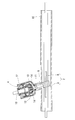
この発明の第1実施形態に係る車両操舵システム用ユニットを図1、図2に基づいて説明する。図示の車両操舵システムは、通常、自動車のステアリングホイール1とラックアンドピニオン2のピニオン3がクラッチ4を介して機械的に連結されておらず、ステアリングホイール1の舵角を電気信号に置き換え、その電気信号に基づいて操舵車輪5の操舵角度を電動操舵アクチュエータ(図示省略)で自動制御すると共に、反力モータ6の自動制御を行ってステアリングホイール1に適切な操舵反力を与える。電動操舵アクチュエータや反力モータ6等に異常が生じた場合、クラッチ4によってステアリングホイール1とピニオン3が連結され、ステアリングホイール1で直接操舵することが可能になるステアバイワイヤ方式のものである。
ステアリングホイール1に第1軸7が連結されている。反力モータ6は、第1軸7に操舵反力を与える。第1軸7は、反力モータ6の出力軸と一体に設けられている。このため、反力モータ6は、第1軸7に操舵反力を直接的に与えることができる。反力モータ6のハウジングは、車体のエンジンルームと運転室を仕切る隔壁に取り付けられる。
ラックアンドピニオン2は、ラック8と、ラック8に噛み合うピニオン3とからなる。ピニオン3に第2軸9が連結されている。ラック8は、電動操舵アクチュエータによって駆動されるようになっている。
クラッチ4は、機械式クラッチ部と、機械式クラッチ部の連結状態又は非連結状態を切り替えるクラッチ切替手段とからなる。機械式クラッチ部は、入力軸10と、出力軸11と、入力軸10と一体に回転する係合面12と、出力軸11と一体に回転する係合面13と、係合面12、13によって形成された楔空間に収まる係合子14とを有する。クラッチ切替手段は、車両操舵システムのコントロール装置(図示省略)によって制御される。クラッチ切替手段が、係合子14を係合面12及び係合面13に係合させると、クラッチ4が連結状態になり、その係合を解除させると、クラッチ4が非連結状態になる。このようなクラッチ4として、例えば、特許文献1や特許文献3に開示されたものを採用することができる。
クラッチ4の入力軸10は、ステアリングホイール1側から常にトルクを入力される部材になっている。クラッチ4の出力軸11は、連結状態のとき、ステアリングホイール1からのトルクをピニオン3側へ出力する部材になっている。
クラッチ4の入力軸10と第1軸7とが、自在継手15によって連結されている。自在継手15は、第1軸7から入力軸10へ所要の作動角をもって回転伝達を行うことが可能な等速ジョイントであればよい。例えば、自在継手15として、ダブルカルダンジョイントを採用することができる。
クラッチ4の出力軸11と、第2軸9とが、一体に設けられている。ここで、「一体に設けられている」とは、すなわち、出力軸11と第2軸9が、同一の部品に形成されていることをいう。
ラックアンドピニオン2のハウジング16と、クラッチ4のハウジング17とが、一体になっている。ここで、「一体になっている」とは、ラックアンドピニオン2を取り囲む空間と、クラッチ4を取り囲む空間と、出力軸11及び第2軸9を通す孔とが一連の空間になっていることをいう。出力軸11は、軸受を介してハウジング17の内周に支持されている。
上述のように構成された第1実施形態によれば、クラッチ4の出力軸11と、第2軸9とを一体に設けているので、常に、出力軸11と第2軸9が同心に固定されている。このため、ステアリングホイール1及びピニオン3間の回転伝達経路は、出力軸11と第2軸9を連結する自在継手をもたず、自在継手15を入力軸10側にのみ用いるだけで構築される。したがって、第1実施形態は、クラッチ4の出力軸11の方でラジアル負荷を無くし、クラッチ4をより安定作動させ易くすることができる。出力軸11側で自在継手を無くすと、結果的に、ラックアンドピニオン2及びクラッチ4間の軸方向距離を従来よりも短くすることも可能になり、前述のハウジングの一体化を容易に行うことができる。
第2実施形態を図3に基づいて説明する。以下、第1実施形態との相違点を述べるに留める。図示のように、第2実施形態では、ラックアンドピニオン2のハウジング16と、クラッチ4のハウジング17とが、別体になっている。別体にしても、出力軸11と第2軸9とが一体に設けられているので、入力軸11と第2軸9の同心固定に影響はない。クラッチ4のハウジング17は、車体のエンジンルームと運転室を仕切る隔壁に取り付けられる。
第3実施形態を図4に基づいて説明する。図示のように、第3実施形態では、クラッチ4の出力軸11と、第2軸9とが、連結手段30によって同心に固定されている。連結手段30は、同心に固定された回転伝達を行えるものであればよく、例えばセレーション、スプライン、フランジが挙げられる。
第4実施形態を図5に基づいて説明する。図示のように、第4実施形態では、反力モータ6のハウジング40と、クラッチ4のハウジング17とが、一体になっている。
クラッチ4の出力軸11と、第2軸9とは、自在継手41によって連結されている。自在継手41は、出力軸11から第2軸9へ所要の作動角をもって回転伝達を行うことが可能な等速ジョイントからなる。
クラッチの入力軸10と、第1軸7とが、一体に設けられている。
第4実施形態によれば、クラッチ4の入力軸10と、第1軸7とを一体に設けているので、常に、入力軸10と第1軸7が同心に固定されている。このため、ステアリングホイール1及びピニオン3間の回転伝達経路は、入力軸10と第1軸7を連結する自在継手をもたず、自在継手41を出力軸11側にのみ用いるだけで構築される。したがって、第4実施形態は、クラッチ4の入力軸10の方でラジアル負荷を無くし、クラッチ4をより安定作動させ易くすることができる。入力軸10側で自在継手を無くすと、結果的に、ステアリングホイール1及びクラッチ4間の軸方向距離を従来よりも短くすることも可能になり、前述のハウジングの一体化を容易に行うことができる。
第5実施形態を図6に基づいて説明する。第5実施形態は、第4実施形態をさらに変更したものなので、ここでは第4実施形態との相違点を述べるに留める。第5実施形態では、クラッチ4の入力軸10と、第1軸7とが、連結手段50によって同心に固定されている。連結手段50は、同心に固定された回転伝達を行えるものであればよい。
第6実施形態を図7に基づいて説明する。第6実施形態は、第4実施形態をさらに変更したものなので、ここでは第4実施形態との相違点を述べるに留める。第6実施形態では、反力モータ6の出力軸61と、第1軸7とが、別体に設けられている。出力軸61には、駆動プーリ62が設けられている。第1軸7には、従動プーリ63が設けられている。従動プーリ63と駆動プーリ62とに伝達ベルト64が巻回されている。反力モータ6が生み出した操舵反力は、駆動プーリ62、伝達ベルト64、従動プーリ63を介して第1軸7に与えられる。このような反力モータ6を用いた操舵反力付与手段として、例えば特許文献2に開示されたものを採用することができる。
この発明の技術的範囲は、上述の各実施形態に限定されず、特許請求の範囲の記載に基づく技術的思想の範囲内での全ての変更を含むものである。
1 ステアリングホイール
2 ラックアンドピニオン
3 ピニオン
4 クラッチ
5 操舵車輪
6 反力モータ
7 第1軸
8 ラック
9 第2軸
10 クラッチの入力軸
11 クラッチの出力軸
15、41 自在継手
16 ラックアンドピニオンのハウジング
17 クラッチのハウジング
30、50 連結手段
40 反力モータのハウジング
61 反力モータの出力軸
2 ラックアンドピニオン
3 ピニオン
4 クラッチ
5 操舵車輪
6 反力モータ
7 第1軸
8 ラック
9 第2軸
10 クラッチの入力軸
11 クラッチの出力軸
15、41 自在継手
16 ラックアンドピニオンのハウジング
17 クラッチのハウジング
30、50 連結手段
40 反力モータのハウジング
61 反力モータの出力軸
Claims (7)
- ステアリングホイール(1)に連結された第1軸(7)、又はラックアンドピニオン(2)のピニオン(3)に連結された第2軸(9)と、
前記第1軸(7)及び前記第2軸(9)間の回転伝達経路に組込まれるクラッチ(4)と、を備え、
前記クラッチ(4)の入力軸(10)と前記第1軸(7)、又は前記クラッチ(4)の出力軸(11)と前記第2軸(9)が、同心に固定されている車両操舵システム用ユニット。 - 前記第1軸(7)に与える操舵反力を生み出す反力モータ(6)のハウジング(40)、又は前記ラックアンドピニオン(2)のハウジング(16)と、前記クラッチ(4)のハウジング(17)とが、一体になっている請求項1に記載の車両操舵システム用ユニット。
- 前記第1軸(7)に与える操舵反力を生み出す反力モータ(6)のハウジング(40)、又は前記ラックアンドピニオン(2)のハウジング(16)と、前記クラッチ(4)のハウジング(17)とが、別体になっている請求項1に記載の車両操舵システム用ユニット。
- 前記第1軸(7)に与える操舵反力を生み出す反力モータ(6)の出力軸(61)、又は前記第1軸(7)と、前記クラッチ(4)の入力軸(10)とが、一体に設けられている請求項1に記載の車両操舵システム用ユニット。
- 前記第1軸(7)に与える操舵反力を生み出す反力モータ(6)の出力軸(61)、又は前記第1軸(7)と、前記クラッチ(4)の入力軸(10)とが、別体に設けられている請求項1に記載の車両操舵システム用ユニット。
- 前記第2軸(9)と前記クラッチ(4)の出力軸(11)とが、一体に設けられている請求項1に記載の車両操舵システム用ユニット。
- 前記第2軸(9)と前記クラッチ(4)の出力軸(11)とが、別体に設けられている請求項1に記載の車両操舵システム用ユニット。
Priority Applications (3)
| Application Number | Priority Date | Filing Date | Title |
|---|---|---|---|
| US15/129,557 US20170113713A1 (en) | 2014-03-28 | 2015-03-26 | Unit for vehicle steering system |
| CN201580011582.6A CN106170429A (zh) | 2014-03-28 | 2015-03-26 | 车辆转向操纵系统用单元 |
| EP15769356.5A EP3124357B1 (en) | 2014-03-28 | 2015-03-26 | Unit for vehicle steering system |
Applications Claiming Priority (2)
| Application Number | Priority Date | Filing Date | Title |
|---|---|---|---|
| JP2014-068407 | 2014-03-28 | ||
| JP2014068407A JP2015189346A (ja) | 2014-03-28 | 2014-03-28 | 車両操舵システム用ユニット |
Publications (1)
| Publication Number | Publication Date |
|---|---|
| WO2015147200A1 true WO2015147200A1 (ja) | 2015-10-01 |
Family
ID=54195704
Family Applications (1)
| Application Number | Title | Priority Date | Filing Date |
|---|---|---|---|
| PCT/JP2015/059452 WO2015147200A1 (ja) | 2014-03-28 | 2015-03-26 | 車両操舵システム用ユニット |
Country Status (5)
| Country | Link |
|---|---|
| US (1) | US20170113713A1 (ja) |
| EP (1) | EP3124357B1 (ja) |
| JP (1) | JP2015189346A (ja) |
| CN (1) | CN106170429A (ja) |
| WO (1) | WO2015147200A1 (ja) |
Families Citing this family (4)
| Publication number | Priority date | Publication date | Assignee | Title |
|---|---|---|---|---|
| CN106741138B (zh) * | 2016-12-16 | 2019-02-19 | 吉林大学 | 一种电动轮驱动汽车的多模式转向系统及控制方法 |
| JP7389579B2 (ja) * | 2019-07-18 | 2023-11-30 | Ntn株式会社 | 回転伝達装置および車両用操舵装置 |
| CN112706825A (zh) * | 2019-10-25 | 2021-04-27 | 比亚迪股份有限公司 | 转向离合器、转向系统和车辆 |
| CN116620392B (zh) * | 2023-07-24 | 2023-09-26 | 成都四海万联科技有限公司 | 一种自动驾驶汽车转向组件 |
Citations (6)
| Publication number | Priority date | Publication date | Assignee | Title |
|---|---|---|---|---|
| JPH0622151U (ja) * | 1992-08-28 | 1994-03-22 | カヤバ工業株式会社 | 動力操舵装置 |
| JP2001506563A (ja) * | 1998-02-07 | 2001-05-22 | ダイムラークライスラー アクチエンゲゼルシヤフト | かじ取りシステム |
| JP2004009989A (ja) * | 2002-06-11 | 2004-01-15 | Toyoda Mach Works Ltd | 車両用操舵装置 |
| US20040039508A1 (en) * | 2002-08-20 | 2004-02-26 | Muqtada Husain | Motor vehicle steering system |
| JP2008184004A (ja) * | 2007-01-29 | 2008-08-14 | Jtekt Corp | 車両用操舵装置 |
| JP2008239112A (ja) * | 2007-03-29 | 2008-10-09 | Fuji Kiko Co Ltd | 車両用操舵装置 |
Family Cites Families (10)
| Publication number | Priority date | Publication date | Assignee | Title |
|---|---|---|---|---|
| DE10015922B4 (de) * | 2000-03-30 | 2006-05-24 | Daimlerchrysler Ag | Lenksystem |
| JP2004237785A (ja) * | 2003-02-04 | 2004-08-26 | Honda Motor Co Ltd | 車両用操舵装置 |
| JP4252392B2 (ja) * | 2003-07-25 | 2009-04-08 | Ntn株式会社 | クラッチ |
| JP4347100B2 (ja) * | 2004-03-17 | 2009-10-21 | Ntn株式会社 | ステアバイワイヤシステム |
| JP2006123857A (ja) * | 2004-11-01 | 2006-05-18 | Toyota Motor Corp | 車両用ステアリング装置 |
| JP4876634B2 (ja) * | 2006-03-01 | 2012-02-15 | 日産自動車株式会社 | 車両用操舵制御装置 |
| JP2008155782A (ja) * | 2006-12-25 | 2008-07-10 | Fuji Kiko Co Ltd | 車両用操舵装置 |
| JP4367520B2 (ja) * | 2007-04-26 | 2009-11-18 | 日産自動車株式会社 | 車両用可変ギヤ比操舵装置 |
| JP5100740B2 (ja) * | 2009-12-02 | 2012-12-19 | 本田技研工業株式会社 | 車両用ステアリング装置 |
| JP5880953B2 (ja) * | 2012-03-22 | 2016-03-09 | 株式会社ジェイテクト | 車両用操舵装置 |
-
2014
- 2014-03-28 JP JP2014068407A patent/JP2015189346A/ja active Pending
-
2015
- 2015-03-26 US US15/129,557 patent/US20170113713A1/en not_active Abandoned
- 2015-03-26 CN CN201580011582.6A patent/CN106170429A/zh active Pending
- 2015-03-26 WO PCT/JP2015/059452 patent/WO2015147200A1/ja active Application Filing
- 2015-03-26 EP EP15769356.5A patent/EP3124357B1/en active Active
Patent Citations (6)
| Publication number | Priority date | Publication date | Assignee | Title |
|---|---|---|---|---|
| JPH0622151U (ja) * | 1992-08-28 | 1994-03-22 | カヤバ工業株式会社 | 動力操舵装置 |
| JP2001506563A (ja) * | 1998-02-07 | 2001-05-22 | ダイムラークライスラー アクチエンゲゼルシヤフト | かじ取りシステム |
| JP2004009989A (ja) * | 2002-06-11 | 2004-01-15 | Toyoda Mach Works Ltd | 車両用操舵装置 |
| US20040039508A1 (en) * | 2002-08-20 | 2004-02-26 | Muqtada Husain | Motor vehicle steering system |
| JP2008184004A (ja) * | 2007-01-29 | 2008-08-14 | Jtekt Corp | 車両用操舵装置 |
| JP2008239112A (ja) * | 2007-03-29 | 2008-10-09 | Fuji Kiko Co Ltd | 車両用操舵装置 |
Also Published As
| Publication number | Publication date |
|---|---|
| JP2015189346A (ja) | 2015-11-02 |
| EP3124357A4 (en) | 2017-04-05 |
| CN106170429A (zh) | 2016-11-30 |
| US20170113713A1 (en) | 2017-04-27 |
| EP3124357B1 (en) | 2019-03-20 |
| EP3124357A1 (en) | 2017-02-01 |
Similar Documents
| Publication | Publication Date | Title |
|---|---|---|
| CN107813861B (zh) | 缆线转向式转向系统的中间轴组件 | |
| WO2015147200A1 (ja) | 車両操舵システム用ユニット | |
| US10556616B2 (en) | Damping coupler of electronic power steering apparatus | |
| US11485403B2 (en) | Rotation limiting means, steering system, and method for limiting a rotational movement in a steering system | |
| US20230045274A1 (en) | Shaft coupling assembly | |
| JP2007145273A (ja) | ステアリング装置 | |
| US20180229759A1 (en) | Restoring torque generating devices | |
| JPWO2016084403A1 (ja) | トルク伝達用継手及び電動式パワーステアリング装置 | |
| JP6396201B2 (ja) | 電動パワーステアリング装置 | |
| US11530723B2 (en) | Power transmission device of steering system | |
| US11384827B2 (en) | Electric power steering polymer drive pulley | |
| CN108284870B (zh) | 用于车辆的转向柱 | |
| JP2009001243A (ja) | 電動パワーステアリング装置 | |
| KR20190104672A (ko) | 스티어 바이 와이어식 조향장치 | |
| JP6375170B2 (ja) | 電動パワーステアリング装置 | |
| US11897305B2 (en) | Active roll stabilizer | |
| JP4952176B2 (ja) | 伝達比可変装置 | |
| JP2009132305A (ja) | 操舵装置 | |
| JP5397662B2 (ja) | 車両用操舵装置 | |
| US10494020B2 (en) | Power steering for a vehicle | |
| JP2009190670A (ja) | 電動パワーステアリング装置 | |
| JP7447713B2 (ja) | 連結構造、ヨーク及びインターミディエートシャフト | |
| KR101246957B1 (ko) | 자동차 조향장치의 중간축 | |
| JP2017149330A (ja) | 車両用操舵装置 | |
| JP2017001562A (ja) | ステアリング制御装置 |
Legal Events
| Date | Code | Title | Description |
|---|---|---|---|
| 121 | Ep: the epo has been informed by wipo that ep was designated in this application |
Ref document number: 15769356 Country of ref document: EP Kind code of ref document: A1 |
|
| WWE | Wipo information: entry into national phase |
Ref document number: 15129557 Country of ref document: US |
|
| NENP | Non-entry into the national phase |
Ref country code: DE |
|
| REEP | Request for entry into the european phase |
Ref document number: 2015769356 Country of ref document: EP |
|
| WWE | Wipo information: entry into national phase |
Ref document number: 2015769356 Country of ref document: EP |