WO2015145493A1 - Dispositif de réception vidéo, procédé de reconnaissance vidéo et système d'affichage d'informations supplémentaires - Google Patents
Dispositif de réception vidéo, procédé de reconnaissance vidéo et système d'affichage d'informations supplémentaires Download PDFInfo
- Publication number
- WO2015145493A1 WO2015145493A1 PCT/JP2014/003762 JP2014003762W WO2015145493A1 WO 2015145493 A1 WO2015145493 A1 WO 2015145493A1 JP 2014003762 W JP2014003762 W JP 2014003762W WO 2015145493 A1 WO2015145493 A1 WO 2015145493A1
- Authority
- WO
- WIPO (PCT)
- Prior art keywords
- video
- information
- recognition
- viewing
- time zone
- Prior art date
Links
Images


Classifications
-
- H—ELECTRICITY
- H04—ELECTRIC COMMUNICATION TECHNIQUE
- H04N—PICTORIAL COMMUNICATION, e.g. TELEVISION
- H04N21/00—Selective content distribution, e.g. interactive television or video on demand [VOD]
- H04N21/20—Servers specifically adapted for the distribution of content, e.g. VOD servers; Operations thereof
- H04N21/23—Processing of content or additional data; Elementary server operations; Server middleware
- H04N21/234—Processing of video elementary streams, e.g. splicing of video streams, manipulating MPEG-4 scene graphs
- H04N21/23418—Processing of video elementary streams, e.g. splicing of video streams, manipulating MPEG-4 scene graphs involving operations for analysing video streams, e.g. detecting features or characteristics
-
- H—ELECTRICITY
- H04—ELECTRIC COMMUNICATION TECHNIQUE
- H04N—PICTORIAL COMMUNICATION, e.g. TELEVISION
- H04N21/00—Selective content distribution, e.g. interactive television or video on demand [VOD]
- H04N21/80—Generation or processing of content or additional data by content creator independently of the distribution process; Content per se
- H04N21/81—Monomedia components thereof
- H04N21/8126—Monomedia components thereof involving additional data, e.g. news, sports, stocks, weather forecasts
- H04N21/8133—Monomedia components thereof involving additional data, e.g. news, sports, stocks, weather forecasts specifically related to the content, e.g. biography of the actors in a movie, detailed information about an article seen in a video program
-
- G—PHYSICS
- G06—COMPUTING; CALCULATING OR COUNTING
- G06F—ELECTRIC DIGITAL DATA PROCESSING
- G06F13/00—Interconnection of, or transfer of information or other signals between, memories, input/output devices or central processing units
-
- G—PHYSICS
- G06—COMPUTING; CALCULATING OR COUNTING
- G06F—ELECTRIC DIGITAL DATA PROCESSING
- G06F16/00—Information retrieval; Database structures therefor; File system structures therefor
-
- G—PHYSICS
- G06—COMPUTING; CALCULATING OR COUNTING
- G06F—ELECTRIC DIGITAL DATA PROCESSING
- G06F16/00—Information retrieval; Database structures therefor; File system structures therefor
- G06F16/70—Information retrieval; Database structures therefor; File system structures therefor of video data
- G06F16/78—Retrieval characterised by using metadata, e.g. metadata not derived from the content or metadata generated manually
- G06F16/783—Retrieval characterised by using metadata, e.g. metadata not derived from the content or metadata generated manually using metadata automatically derived from the content
- G06F16/7837—Retrieval characterised by using metadata, e.g. metadata not derived from the content or metadata generated manually using metadata automatically derived from the content using objects detected or recognised in the video content
-
- G—PHYSICS
- G06—COMPUTING; CALCULATING OR COUNTING
- G06V—IMAGE OR VIDEO RECOGNITION OR UNDERSTANDING
- G06V20/00—Scenes; Scene-specific elements
- G06V20/40—Scenes; Scene-specific elements in video content
- G06V20/46—Extracting features or characteristics from the video content, e.g. video fingerprints, representative shots or key frames
-
- G—PHYSICS
- G06—COMPUTING; CALCULATING OR COUNTING
- G06V—IMAGE OR VIDEO RECOGNITION OR UNDERSTANDING
- G06V20/00—Scenes; Scene-specific elements
- G06V20/40—Scenes; Scene-specific elements in video content
- G06V20/48—Matching video sequences
-
- H—ELECTRICITY
- H04—ELECTRIC COMMUNICATION TECHNIQUE
- H04N—PICTORIAL COMMUNICATION, e.g. TELEVISION
- H04N21/00—Selective content distribution, e.g. interactive television or video on demand [VOD]
- H04N21/20—Servers specifically adapted for the distribution of content, e.g. VOD servers; Operations thereof
- H04N21/23—Processing of content or additional data; Elementary server operations; Server middleware
- H04N21/234—Processing of video elementary streams, e.g. splicing of video streams, manipulating MPEG-4 scene graphs
- H04N21/23424—Processing of video elementary streams, e.g. splicing of video streams, manipulating MPEG-4 scene graphs involving splicing one content stream with another content stream, e.g. for inserting or substituting an advertisement
-
- H—ELECTRICITY
- H04—ELECTRIC COMMUNICATION TECHNIQUE
- H04N—PICTORIAL COMMUNICATION, e.g. TELEVISION
- H04N21/00—Selective content distribution, e.g. interactive television or video on demand [VOD]
- H04N21/20—Servers specifically adapted for the distribution of content, e.g. VOD servers; Operations thereof
- H04N21/23—Processing of content or additional data; Elementary server operations; Server middleware
- H04N21/237—Communication with additional data server
-
- H—ELECTRICITY
- H04—ELECTRIC COMMUNICATION TECHNIQUE
- H04N—PICTORIAL COMMUNICATION, e.g. TELEVISION
- H04N21/00—Selective content distribution, e.g. interactive television or video on demand [VOD]
- H04N21/20—Servers specifically adapted for the distribution of content, e.g. VOD servers; Operations thereof
- H04N21/25—Management operations performed by the server for facilitating the content distribution or administrating data related to end-users or client devices, e.g. end-user or client device authentication, learning user preferences for recommending movies
- H04N21/258—Client or end-user data management, e.g. managing client capabilities, user preferences or demographics, processing of multiple end-users preferences to derive collaborative data
- H04N21/25808—Management of client data
- H04N21/25841—Management of client data involving the geographical location of the client
-
- H—ELECTRICITY
- H04—ELECTRIC COMMUNICATION TECHNIQUE
- H04N—PICTORIAL COMMUNICATION, e.g. TELEVISION
- H04N21/00—Selective content distribution, e.g. interactive television or video on demand [VOD]
- H04N21/40—Client devices specifically adapted for the reception of or interaction with content, e.g. set-top-box [STB]; Operations thereof
- H04N21/43—Processing of content or additional data, e.g. demultiplexing additional data from a digital video stream; Elementary client operations, e.g. monitoring of home network or synchronising decoder's clock; Client middleware
- H04N21/431—Generation of visual interfaces for content selection or interaction; Content or additional data rendering
- H04N21/4312—Generation of visual interfaces for content selection or interaction; Content or additional data rendering involving specific graphical features, e.g. screen layout, special fonts or colors, blinking icons, highlights or animations
- H04N21/4316—Generation of visual interfaces for content selection or interaction; Content or additional data rendering involving specific graphical features, e.g. screen layout, special fonts or colors, blinking icons, highlights or animations for displaying supplemental content in a region of the screen, e.g. an advertisement in a separate window
-
- H—ELECTRICITY
- H04—ELECTRIC COMMUNICATION TECHNIQUE
- H04N—PICTORIAL COMMUNICATION, e.g. TELEVISION
- H04N21/00—Selective content distribution, e.g. interactive television or video on demand [VOD]
- H04N21/40—Client devices specifically adapted for the reception of or interaction with content, e.g. set-top-box [STB]; Operations thereof
- H04N21/43—Processing of content or additional data, e.g. demultiplexing additional data from a digital video stream; Elementary client operations, e.g. monitoring of home network or synchronising decoder's clock; Client middleware
- H04N21/437—Interfacing the upstream path of the transmission network, e.g. for transmitting client requests to a VOD server
-
- H—ELECTRICITY
- H04—ELECTRIC COMMUNICATION TECHNIQUE
- H04N—PICTORIAL COMMUNICATION, e.g. TELEVISION
- H04N21/00—Selective content distribution, e.g. interactive television or video on demand [VOD]
- H04N21/40—Client devices specifically adapted for the reception of or interaction with content, e.g. set-top-box [STB]; Operations thereof
- H04N21/43—Processing of content or additional data, e.g. demultiplexing additional data from a digital video stream; Elementary client operations, e.g. monitoring of home network or synchronising decoder's clock; Client middleware
- H04N21/44—Processing of video elementary streams, e.g. splicing a video clip retrieved from local storage with an incoming video stream, rendering scenes according to MPEG-4 scene graphs
- H04N21/44008—Processing of video elementary streams, e.g. splicing a video clip retrieved from local storage with an incoming video stream, rendering scenes according to MPEG-4 scene graphs involving operations for analysing video streams, e.g. detecting features or characteristics in the video stream
-
- H—ELECTRICITY
- H04—ELECTRIC COMMUNICATION TECHNIQUE
- H04N—PICTORIAL COMMUNICATION, e.g. TELEVISION
- H04N21/00—Selective content distribution, e.g. interactive television or video on demand [VOD]
- H04N21/40—Client devices specifically adapted for the reception of or interaction with content, e.g. set-top-box [STB]; Operations thereof
- H04N21/45—Management operations performed by the client for facilitating the reception of or the interaction with the content or administrating data related to the end-user or to the client device itself, e.g. learning user preferences for recommending movies, resolving scheduling conflicts
- H04N21/462—Content or additional data management, e.g. creating a master electronic program guide from data received from the Internet and a Head-end, controlling the complexity of a video stream by scaling the resolution or bit-rate based on the client capabilities
- H04N21/4622—Retrieving content or additional data from different sources, e.g. from a broadcast channel and the Internet
-
- H—ELECTRICITY
- H04—ELECTRIC COMMUNICATION TECHNIQUE
- H04N—PICTORIAL COMMUNICATION, e.g. TELEVISION
- H04N21/00—Selective content distribution, e.g. interactive television or video on demand [VOD]
- H04N21/60—Network structure or processes for video distribution between server and client or between remote clients; Control signalling between clients, server and network components; Transmission of management data between server and client, e.g. sending from server to client commands for recording incoming content stream; Communication details between server and client
- H04N21/65—Transmission of management data between client and server
- H04N21/658—Transmission by the client directed to the server
- H04N21/6582—Data stored in the client, e.g. viewing habits, hardware capabilities, credit card number
-
- H—ELECTRICITY
- H04—ELECTRIC COMMUNICATION TECHNIQUE
- H04N—PICTORIAL COMMUNICATION, e.g. TELEVISION
- H04N21/00—Selective content distribution, e.g. interactive television or video on demand [VOD]
- H04N21/80—Generation or processing of content or additional data by content creator independently of the distribution process; Content per se
- H04N21/83—Generation or processing of protective or descriptive data associated with content; Content structuring
- H04N21/84—Generation or processing of descriptive data, e.g. content descriptors
-
- H—ELECTRICITY
- H04—ELECTRIC COMMUNICATION TECHNIQUE
- H04N—PICTORIAL COMMUNICATION, e.g. TELEVISION
- H04N5/00—Details of television systems
- H04N5/222—Studio circuitry; Studio devices; Studio equipment
- H04N5/262—Studio circuits, e.g. for mixing, switching-over, change of character of image, other special effects ; Cameras specially adapted for the electronic generation of special effects
- H04N5/265—Mixing
Definitions
- the present disclosure relates to a video receiving apparatus that acquires additional information related to a video signal input from the outside and superimposes the additional information on the video signal.
- Patent Document 1 discloses a data processing system.
- a client device transmits video data through a network to a server device that is a video recognition device, and requests video recognition processing.
- the server device performs video recognition based on the received video data, and transmits the video recognition result to the client device through the network.
- This disclosure provides a video receiving apparatus, a video recognition method, and an additional information display system that are effective for acquiring additional information related to an externally input video signal and superimposing the acquired additional information on the video signal.
- the video reception device of the present disclosure is configured to be able to transmit and receive data via a communication network, and includes an input unit, a video extraction unit, a storage unit, a video recognition unit, and a control unit.
- the input unit is configured to input a video signal output from a video transmission device installed outside.
- the video extraction unit is configured to extract a partial video for video recognition processing from the video signal.
- the storage unit is configured to store a local database generated based on the local database generation information in the video recognition apparatus connected to the communication network.
- the video recognition unit generates second content recognition information from the partial video, transmits the second content recognition information to the video recognition device, and requests video recognition processing; and second content recognition information At least one of local matching processing for collating with the first content recognition information included in the local database stored in the storage unit.
- the control unit performs control for acquiring a local database from the video recognition device, and acquires additional information based on the result of online matching processing or the result of local matching processing from the additional information distribution device connected to the communication network. Is configured to do.
- the video recognition method of the present disclosure is a video recognition method in a video reception device configured to be able to transmit and receive data via a communication network, and a partial video for video recognition processing is obtained from a video signal input from the outside.
- a step of extracting, a step of acquiring a local database generated based on the local database generation information in a video recognition device connected to a communication network and storing the local database in a storage unit; and generating second content recognition information from the partial video A step of transmitting the second content recognition information to the video recognition device to request the video recognition processing, and a first database included in the local database stored in the storage unit.
- the additional information display system of the present disclosure includes a video reception device, a video recognition device, and an additional information distribution device configured to be able to transmit and receive data to and from each other via a communication network.
- the video reception device includes an input unit, a video extraction unit, a storage unit, a video recognition unit, and a control unit.
- the input unit is configured to input a video signal output from a video transmission device installed outside.
- the video extraction unit is configured to extract a partial video for video recognition from the video signal.
- the storage unit is configured to store a local database generated based on the local database generation information in the video recognition apparatus.
- the video recognition unit generates second content recognition information from the partial video, transmits the second content recognition information to the video recognition device via the communication network, and requests video recognition processing;
- the second content recognition information is configured to perform at least one of local matching processing for collating with the first content recognition information included in the local database stored in the storage unit.
- the control unit performs control for acquiring a local database from the video recognition device via the communication network, and transmits additional information based on the online matching processing result or the local matching processing result from the additional information distribution device via the communication network. It is configured to perform acquisition control.
- the video recognition device generates and stores first content recognition information from the acquired video signal, and selects first content recognition information related to local database generation information from the generated first content recognition information
- the second content recognition information received via the communication network is collated with the stored first content recognition information, and online matching is configured to generate a local database and transmit it to the video receiver. It is configured to perform processing.
- the additional information distribution device is configured to transmit additional information corresponding to the result of online matching processing or the result of local matching processing received via the communication network to the video reception device via the communication network.
- FIG. 1 is a diagram schematically showing an example of the configuration of the additional information display system in the first embodiment.
- FIG. 2 is a schematic diagram schematically showing an example of the operation of the video recognition apparatus in the first embodiment.
- FIG. 3 is a block diagram schematically showing an example of the configuration of the video recognition apparatus and the video reception apparatus in the first embodiment.
- FIG. 4 is a schematic diagram schematically showing an overview of the online matching process and the local matching process of the additional information display system according to the first embodiment.
- FIG. 5 is a flowchart schematically showing an operation of additional information display processing performed by the video reception device in the first embodiment.
- FIG. 6 is a flowchart schematically showing the operation of the content specifying process performed by the video receiving apparatus in the first embodiment.
- FIG. 7 is a flowchart schematically showing an operation of local matching processing performed by the video reception device in the first embodiment.
- FIG. 8 is a flowchart schematically showing the operation of the online matching process performed by the video reception device and the video recognition device in the first embodiment.
- FIG. 9 is a flowchart schematically showing an operation of local database update processing performed by the video reception device and the video recognition device in the first exemplary embodiment.
- FIG. 10 is a flowchart schematically showing the operation of the next viewing information generation process performed by the video reception device in the first embodiment.
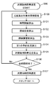
- FIG. 11 is a flowchart schematically showing the operation of the next viewing time zone selection process performed by the video reception device in the first embodiment.
- FIG. 12 is a schematic diagram schematically showing an example of the operation of the next viewing time zone selection process performed by the video reception device in the first embodiment.
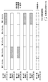
- FIG. 13 is a diagram illustrating an example of the next viewing time zone likelihood calculated by the video recognition unit of the video reception device in the first embodiment.
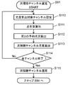
- FIG. 14 is a flowchart schematically showing the operation of the next viewing channel selection process performed by the video reception device in the first embodiment.
- FIG. 15 is a schematic diagram schematically illustrating an example of the operation of the next viewing channel selection process performed by the video reception device in the first embodiment.
- FIG. 16 is a diagram illustrating an example of the next viewing channel likelihood calculated by the video recognition unit of the video reception device in the first embodiment.
- FIG. 17 is a flowchart schematically showing an operation of content identification processing performed by the video reception device in another embodiment.
- FIG. 18 is a flowchart schematically illustrating an example of an operation of local database update processing performed by a video reception device and a video recognition device according to another embodiment.
- FIG. 19 is a flowchart schematically illustrating another example of the operation of the local database update process performed by the video reception device and the video recognition device according to another embodiment.
- FIG. 20 is a block diagram schematically illustrating an example of a configuration of a video recognition device and a video reception device according to another embodiment.
- FIG. 1 is a diagram schematically showing an example of a configuration of an additional information display system 10 according to the first embodiment.
- the additional information display system 10 includes a broadcasting station 12, an STB (Set Top Box) 14 that is a video transmission device, a video recognition device 20, an additional information distribution device 30, and a video reception device 40.
- the additional information display system 10 uses the video recognition technology of the video recognition device 20 to identify which content the video received by the video reception device 40 belongs to, and adds additional information related to the content to the additional information.
- the communication system is configured to be able to acquire from the distribution device 30 and display it on the video reception device 40.
- the video receiving device 40, the video recognition device 20, and the additional information distribution device 30 are connected to each other via the communication network 16.
- the communication network 16 is configured by wired, wireless, or a mixture of both.
- the communication network 16 is, for example, the Internet, but may be an intranet, a commercial line, other communication lines, or a mixture thereof.
- the video receiver 40 and the STB 14 are connected to each other via a communication interface.
- the communication interface is, for example, HDMI (registered trademark) (High-Definition Multimedia Interface), but may be a video cable, or may be Wi-Fi (registered trademark), Bluetooth (registered trademark), or wireless LAN (Local Area Network). ) Or the like.
- Broadcast station 12 is a transmission device configured to transmit (broadcast) a broadcast signal.
- the broadcast station 12 converts a television program including a program body and a commercial message (CM) into a video signal and superimposes it on the broadcast signal and broadcasts it.
- the program body and the CM are switched to each other as time passes.
- the program body and CM are referred to as “content”.
- the broadcast station 12 broadcasts content that changes over time.
- the transmission device is not limited to the broadcasting station 12 and may be any device that transmits or broadcasts content that changes over time.
- the STB 14 is a receiver (tuner) configured to receive a broadcast signal broadcast by the broadcast station 12 and extract a video signal.
- the STB 14 may have a function of decoding the received video signal.
- the STB 14 receives a channel selected based on a user's (User) instruction from a plurality of channels broadcasted by the broadcast station 12, and transmits a video interface of the channel to a communication interface (for example, HDMI (registered trademark)).
- a communication interface for example, HDMI (registered trademark)
- the video transmission apparatus is not limited to the STB 14, and may be a recording apparatus having a recording function, a broadcast signal receiving function, and a video signal output function, for example.
- the video recognition device 20 is a server device connected to the communication network 16 and is a Web site that performs content specifying processing based on video recognition processing.
- the content identification process is a video recognition process based on the second content recognition information transmitted from the video receiver 40 via the communication network 16, and the second content recognition information based on the result of the video recognition process. Is a process of specifying the content represented by.
- the video recognition device 20 acquires and analyzes content (video signal) broadcasted by the broadcast station 12, generates first content recognition information and analysis information from the content, and stores them. Store in the unit 23.
- the first content recognition information is, for example, a hash value of each image constituting the moving image.
- the first content recognition information is also referred to as “server video recognition information”.
- the video recognition device 20 collates the received second content recognition information with “server video recognition information” that the video recognition device 20 previously generates and stores in the storage unit 23 (video recognition processing). Based on the result of the collation, the content is specified (content specifying process), and the analysis information related to the specified content is returned to the video receiving device 40.
- the video recognition device 20 receives a huge number of contents broadcasted by the broadcasting station 12, analyzes them, and stores the results in the storage unit 23. Therefore, the amount of information stored in the storage unit 23 is also huge. .
- a collection of information stored in the storage unit 23 (information used for content identification processing) is referred to as an “online database”.
- the video recognition apparatus 20 selects predetermined first content recognition information (server video recognition information) and analysis information from the online database of such a large amount of information, generates a “local database”, and transmits it to the video reception apparatus 40. Also do.
- the video receiving device 40 is a video receiving device configured to display video based on a video signal input from the outside on the display unit 54, and is, for example, a television receiver.
- the video receiving device 40 is connected to the communication network 16 and can transmit and receive data to and from the video recognition device 20 and the additional information distribution device 30 via the communication network 16.
- the video receiving device 40 in the present embodiment is configured to be able to:
- the video receiving device 40 performs content specifying processing (content specifying processing based on the video recognition processing) on the video signal input from the video transmitting device (for example, STB 14) via the communication interface, using the video recognition device 20.
- the content specifying process is a process for specifying the content represented by the video signal as described above.
- the video reception device 40 receives the analysis information transmitted from the video recognition device 20 as a result of the content specifying process, and distributes additional information (for example, advertisement information) related to the content based on the analysis information.
- the additional information acquired from the device 30 is superimposed on the video signal and displayed on the display unit 54.
- the video reception device 40 periodically extracts a partial video by periodically cutting out a part from the input video signal, and the second content recognition information generated from the partial video and content identification
- a request for processing (content identification processing based on video recognition processing) is transmitted to the video recognition device 20 via the communication network 16.
- the second content recognition information is, for example, a hash value of each image constituting the partial video.
- the second content recognition information generated by the video reception device 40 is also referred to as “terminal video recognition information”.
- the request for content identification processing transmitted from the video reception device 40 to the video recognition device 20 is also referred to as a “video recognition request”.
- the video reception device 40 acquires the result (analysis information) of the content specifying process for the second content recognition information from the video recognition device 20 via the communication network 16.
- the content specifying process (content specifying process based on the video recognizing process) performed by the video receiving apparatus 40 using the video recognizing apparatus 20 is referred to as “online matching process”.
- the video receiving device 40 receives the “local database” transmitted from the video recognition device 20 and stores it in the storage unit 47.
- the local database includes first content recognition information (server video recognition information) generated by the video recognition device 20 and analysis information.
- the video receiving device 40 collates the terminal video recognition information with the local database stored in the storage unit 47 to perform content specifying processing, and stores analysis information based on the result. An operation of reading from the unit 47 is also performed.
- the content specifying process performed using the local database stored in the storage unit 47 is referred to as “local matching process”.
- the video reception device 40 acquires additional information related to the analysis information acquired as a result of the online matching processing or the local matching processing from the additional information distribution device 30 via the communication network 16. Then, an image based on the acquired additional information (shown as “additional information 51” in FIG. 1) is displayed superimposed on the video being displayed on the display unit. Details of these will be described later.
- the content recognition information is information for recognizing a video
- the fingerprint is a hash value of each image constituting a partial video or a moving image.
- the content recognition information only needs to be information (data) that can be used for video recognition processing, and is not limited to a fingerprint (hash value).
- the additional information distribution device 30 is a server device connected to the communication network 16 and is a Web site (advertisement distribution site) that holds and distributes advertisement information of various products.
- the additional information distribution device 30 obtains the result of the content specifying process transmitted from the video receiving device 40 (the analysis information acquired by the video receiving device 40 from the video recognition device 20 as the result of the online matching processing or the result of the local matching processing).
- the analysis information read out from the storage unit 47 via the communication network 16
- additional information related to the analysis information is transmitted to the video receiver 40 via the communication network 16.
- This additional information is, for example, advertisement information related to the content specified by the content specifying process.
- the additional information is not limited to advertisement information.
- tourism information for example, tourism information, history information, person profile information, URL (Uniform Resource Locator), public gazette information, information about programs being broadcast, Twitter (registered trademark) Social information such as, etc. may be used.
- URL Uniform Resource Locator
- public gazette information information about programs being broadcast, Twitter (registered trademark) Social information such as, etc. may be used.
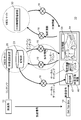
- FIG. 2 is a schematic diagram schematically showing an example of the operation of the video recognition apparatus 20 in the first embodiment. Note that FIG. 2 schematically shows the flow of signals and information, and does not show the configuration of the circuit block.
- the video recognition device 20 acquires substantially all content 81 broadcast from the broadcasting station 12. Then, the acquired content is analyzed, and the time, capacity, broadcast format, content, genre, characters, time table, etc. of the content are checked to generate analysis information 83. In addition, the video recognition device 20 creates a fingerprint 84 that is second content recognition information from the video signal of the content 81 acquired from the broadcast station 12.
- the video recognition apparatus 20 may acquire a content by receiving a broadcast signal broadcast from a broadcast station, or receive a video signal transmitted from the broadcast station 12 via a dedicated video line or the like and receive the content. May be obtained. Moreover, this analysis may be performed automatically, for example, and may be performed manually by an operator.
- the analysis information 83 and the fingerprint 84 which are the analysis results, are stored in the storage unit 23 of the video recognition device 20 together with information about the content 81. Therefore, a huge amount of information is stored in the storage unit 23.
- the video recognition device 20 performs online matching processing when requested by the video reception device 40.
- the video recognition device 20 is accompanied by a fingerprint 82 (terminal video recognition information; second content recognition information generated from a partial video of the video signal 91 output from the STB 14) transmitted from the video reception device 40.
- the fingerprint 82 is collated with the fingerprint 84 (server image recognition information) which is the first content recognition information stored in the storage unit 23 (image recognition). Processing), the content corresponding to the fingerprint 82 is specified.
- a fingerprint 84 whose similarity to the fingerprint 82 is a predetermined numerical value (for example, 60%) or more may be used as a fingerprint corresponding to the fingerprint 82.
- the video recognition device 20 performs content specifying processing for determining what content the partial image of the fingerprint 82 transmitted from the video receiving device 40 is created and specifying the content. Then, an analysis result (analysis information 83) related to the specified content is read from the storage unit 23, and the read analysis information 83 is returned to the video reception device 40 via the communication network 16 as a result of the content specifying process. Details of this online matching process will be described later.
- the video recognition processing (content identification processing based on the video recognition processing) by such a method is also referred to as “ACR (Automatic Content Recognition)”.
- the storage unit 23 of the video recognition device 20 is configured so as to be able to exchange data with the main body of the video recognition device 20 via, for example, the communication network 16, a different location from the main body of the video recognition device 20. It may be installed in.
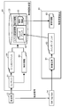
- FIG. 3 is a block diagram schematically showing an example of the configuration of the video recognition device 20 and the video reception device 40 in the first embodiment.
- FIG. 3 shows main circuit blocks related to the operation shown in this embodiment, and other functions and circuit blocks related to the operation are omitted. This is for easy understanding of the operation described in the present embodiment.
- Each circuit block shown in FIG. 3 may be composed of independent circuits, or a program created to realize one or more of the circuit blocks shown in FIG. 3 is executed by a processor. It may be configured to.
- the first content recognition information and the second content recognition information are simply abbreviated as “fingerprints”.
- the video recognition device 20 is a server device including an HTTP (Hypertext Transfer Protocol) transmission / reception unit 21, a search unit 22, and a storage unit 23.
- the video recognition device 20 is used for online matching processing of the video reception device 40 and is configured to provide a content identification processing service based on the video recognition processing to the video reception device 40 via the communication network 16.
- the HTTP transmission / reception unit 21 is a communication interface, for example, a communication adapter conforming to the Ethernet (registered trademark) standard.
- the HTTP transmission / reception unit 21 is configured to be able to transmit / receive data to / from the video reception device 40 via the communication network 16.
- the storage unit 23 is a storage device composed of, for example, an HDD (Hard Disk Drive) or the like.
- the storage unit 23 is configured to store a fingerprint of content broadcast from the broadcasting station 12 and analysis information of an analysis result for the content in association with the content.
- the storage unit 23 has a slight time delay (for example, 10 seconds) from the broadcast for each content (for example, the program main body or CM).
- the fingerprint and the analysis result (analysis information) are stored in association with each other.
- the analysis result (analysis information) may include, for example, a program title, a CM title, a program outline, a CM outline, a character, a location related to a video, a URL, and the like.
- the storage unit 23 may store fingerprints and analysis information such as dramas, movies, and CMs whose broadcast contents are determined in advance, or it is known in advance that they are displayed during the broadcast. Fingerprints and analysis information relating to program titles, company and product logos, performer information, and the like may be stored.
- the search unit 22 When the search unit 22 receives a video recognition request accompanied by a fingerprint (terminal video recognition information) transmitted from the video receiving device 40 via the HTTP transmission / reception unit 21, the content based on the video recognition process using the fingerprint. A specific process is performed, and the result (analysis information) is returned to the video reception device 40 via the HTTP transmission / reception unit 21.
- the search unit 22 receives a video recognition request accompanied by a fingerprint (terminal video recognition information) transmitted from the video receiving device 40 via the communication network 16 and the HTTP transmission / reception unit 21.
- the received fingerprint (terminal video recognition information) is collated with the fingerprint (server video recognition information) stored in the storage unit 23 to search for a fingerprint corresponding to the received fingerprint (video recognition). processing).
- the content corresponding to the fingerprint specified by the search result is set as the content corresponding to the received fingerprint (content specifying process). In this way, the search unit 22 specifies content corresponding to the received fingerprint.
- the search part 22 reads the analysis result (analysis information) matched with the specified content from the memory
- a reply is made to the video receiver 40 via the communication network 16.
- the video receiver 40 includes a control unit 41, an HTTP transmission / reception unit 42, an operation signal reception unit 43, a video output unit 44, a display unit 54, a video extraction unit 45, an additional information display control unit 46, a storage unit 47, and a video input unit 48. And a video recognition unit 66.
- the video receiving device 40 is configured to perform content identification processing based on video recognition processing using the video recognition device 20 (online matching processing), and acquire analysis information as a result of the content identification processing from the video recognition device 20. Has been.
- the video reception device 40 performs content identification processing based on video recognition processing using a local database stored in the storage unit 47 (local matching processing), and stores analysis information based on the result of the content identification processing. It is also configured to read from.
- the video receiving device 40 acquires additional information (for example, advertisement information) related to the analysis information from the additional information distribution device 30, and adds the additional information (for example, the content) to the video (content) by the received video signal.
- additional information for example, advertisement information
- An image based on advertisement information related to video is superimposed and displayed on the display unit 54.
- the HTTP transmission / reception unit 42 is a communication interface, for example, a communication adapter that conforms to the Ethernet (registered trademark) standard.
- the HTTP transmission / reception unit 42 is configured to be able to transmit / receive data to / from the video recognition device 20 via the communication network 16.
- the operation signal reception unit 43 receives an operation signal (operation signal for the video reception device 40) transmitted by an operation unit (not shown) such as a remote control device (hereinafter abbreviated as “remote control”) that has received a user operation. Is configured to do.
- the operation signal receiving unit 43 may be configured such that a remote controller having a gyro sensor receives a signal that is transmitted based on a physical variation that occurs in the remote controller.
- the video input unit 48 is a receiving circuit and a decoder, and inputs a video signal output from a receiving unit 49 configured to receive a broadcast signal transmitted from a broadcast station and a video transmission device (for example, the STB 14).
- the input unit 65 is configured as follows.
- the video signal received by the video input unit 48 includes content (program body and CM, etc.) that changes over time.
- the receiving unit 49 is configured to receive a broadcast signal transmitted from the broadcast station 12 via an antenna (not shown) or the like.
- the input unit 65 is an interface configured to input a video signal output from a video transmission device installed outside.
- the input unit 65 is configured to conform to, for example, the HDMI (registered trademark) standard, and can receive a video signal transmitted from the video transmission device via the HDMI (registered trademark).
- the video transmission device is, for example, the STB 14, but may be a video recording / playback device or the like. Further, the input unit may be configured to receive a video signal transmitted via a video cable or a video signal transmitted by wireless communication.
- the video output unit 44 has a function of controlling the display unit 54, controls the display unit 54 based on the video signal input from the video input unit 48, and displays a video based on the video signal on the display unit 54. It is configured as follows. When the additional information is input from the control unit 41, the video output unit 44 superimposes an image based on the additional information on the video being displayed on the display unit 54.
- the display unit 54 is a display configured to display an image based on an image signal, and is, for example, an LCD (Liquid Crystal Display).
- the display unit 54 may be a PDP (Plasma Display Panel), an OLED (Organic Electro Luminescence Display), or the like.
- the additional information display control unit 46 is configured to perform display control of additional information. Specifically, the additional information display control unit 46 determines whether or not to display the additional information acquired from the additional information distribution device 30 on the display unit 54 based on the analysis information acquired as a result of the online matching process or the local matching process. It is determined whether or not the additional information being displayed on the display unit 54 is to be continuously displayed or not displayed, and an instruction based on the determination is output to the control unit 41. Further, the additional information display control unit 46 determines where the image (or character string) based on the acquired additional information is to be superimposed on the video being displayed on the display unit 54, and gives an instruction based on the determination to the control unit 41 is output.
- the video extraction unit 45 is configured to extract a partial video from the video signal input from the video input unit 48.
- the video extraction unit 45 is configured to extract a partial video that is a part of the video signal for a predetermined time from the video signal at a predetermined cycle. For example, if the predetermined period is 3 seconds and the predetermined time is 3 seconds, the video extraction unit 45 repeats the operation of extracting a partial video of 3 seconds every 3 seconds from the video signal. That is, the operation of continuously extracting the partial video for 3 seconds from the video signal every 3 seconds without a gap is repeated. For example, if the predetermined period is 15 seconds and the predetermined time is 3 seconds, the video extraction unit 45 repeats the operation of extracting a partial video of 3 seconds every 15 seconds from the video signal.
- the partial video extracted from the video signal is not limited to extraction in units of seconds.
- the partial video may be extracted with a predetermined number of frames at the video frame rate.
- the video recognition unit 66 generates a fingerprint (terminal video recognition information) from the partial video extracted by the video extraction unit 45.
- This fingerprint is, for example, a hash value (fingerprint) of each image constituting the partial video.
- the video recognition unit 66 uses a fingerprint generated from the partial video to perform local matching processing for performing content identification processing within the video reception device 40 and online matching processing for performing content identification processing using the video recognition device 20. At least one of the above is performed, and analysis information regarding the partial video is acquired.
- the storage unit 47 is a storage device configured by, for example, a nonvolatile memory.
- the storage unit 47 displays program meta information such as an electronic program guide (EPG) received by the video input unit 48, additional information acquired from the additional information distribution device 30 via the HTTP transmission / reception unit 42, and display of additional information.
- EPG electronic program guide
- Local information including control information, fingerprints (terminal image recognition information) generated from partial images by the image recognition unit 66, fingerprints (server image recognition information) transmitted from the image recognition device 20, and analysis information, etc.
- the display control information for the additional information is information for controlling the display of the additional information, and includes information indicating the display period of the additional information, for example.
- the storage unit 47 also stores information related to the viewing history of the video reception device 40.
- the control unit 41 is configured to control each circuit block included in the video reception device 40.
- the control unit 41 is, for example, a nonvolatile memory such as a ROM that stores a program (application program or the like), a CPU that executes the program, and temporarily stores data, parameters, and the like when the CPU executes the program. It consists of a volatile memory such as a RAM for storing.
- Examples of the control performed by the control unit 41 include the following.
- the control unit 41 controls the video extraction unit 45 so that the video extraction unit 45 extracts partial videos from the video signal at a predetermined cycle. Further, the control unit 41 generates (calculates) a fingerprint (terminal video recognition information) from the partial video, and controls the video recognition unit 66 to perform online matching processing or local matching processing based on the generated fingerprint. And when performing an online matching process, the control part 41 transmits a fingerprint (terminal video recognition information) to the video recognition apparatus 20 via the HTTP transmission / reception part 42 and the communication network 16 with the video recognition request
- control unit 41 acquires the result (analysis information) of the content specifying process for the fingerprint from the video recognition device 20 via the communication network 16 and the HTTP transmission / reception unit 42 and stores them in the storage unit 47.
- Control circuit blocks When performing the local matching process, the control unit 41 collates the fingerprint (terminal video recognition information) with the local database stored in the storage unit 47, performs the content specifying process, and the result of the content specifying process Each circuit block is controlled so that the analysis information based on the data is read from the storage unit 47. Then, the control unit 41 acquires additional information corresponding to the analysis information obtained as a result of the online matching process or the local matching process from the additional information distribution device 30 via the communication network 16 and the HTTP transmission / reception unit 42. Control each circuit block.
- the acquired additional information is stored in the storage unit 47 and output to the video output unit 44, and each circuit block is controlled so that the additional information is superimposed on the video being displayed on the display unit 54 and displayed.
- the additional information display control unit 46 determines that “additional information is not displayed”, the control unit 41 sets each circuit block so that the additional information being displayed on the display unit 54 is not displayed. Control.
- the video receiving device 40 When the video receiving device 40 requests the video recognition device 20 to perform online matching processing, the video receiving device 40 creates a signal (data) representing the request for online matching processing, and uses the signal as a video recognition request.
- the additional information display system 10 may be configured to transmit to the image receiving device 20, for example, such a signal (data) is not transmitted, and the image receiving device 40 transmits the fingerprint to the image recognizing device 20.
- an arrangement may be made in advance between the video receiving device 40 and the video recognizing device 20 so as to request the video recognizing device 20 to perform an online matching process.
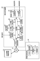
- FIG. 4 is a schematic diagram schematically showing an overview of the online matching process and the local matching process of the additional information display system 10 according to the first embodiment.
- FIG. 4 schematically shows the flow of signals and information, and does not show the configuration of the circuit block.
- the video receiving device 40 and the video recognizing device 20 cooperate with each other, and a content specifying process based on the video recognizing process (input from the video transmitting device such as the STB 14 to the video receiving device 40 is performed. Content specifying process regarding the video signal to be performed).
- the amount of data in the online database stored in the storage unit 23 of the video recognition device 20 is enormous. Therefore, in the online matching process, it is possible to perform highly accurate content specifying processing, but the fingerprint (terminal video recognition information) transmitted from the video receiving device 40 and the online database are stored in the storage unit 23. It takes time to collate with the fingerprint (server image recognition information).
- the video recognition apparatus 20 can narrow the search target range to that viewing channel. The collation can be completed in a relatively short time. However, if the current viewing channel is unknown, such as immediately after the video receiver 40 is turned on or immediately after the channel is changed, the search target range is expanded to all channels. Takes a long time.
- the online matching process requires time for transmitting and receiving data via the communication network 16.
- the local database stored in the storage unit 47 of the video reception device 40 is generated by the fingerprint (server video recognition information) selected from the online database by the video recognition device 20 and analysis information.
- the amount of data is small. That is, the local matching process is a content specifying process that is performed by collating the fingerprint (terminal video recognition information) generated by the video receiving device 40 with a local database having a smaller data amount than the online database. Furthermore, in the local matching process, it is not necessary to transmit / receive data via the communication network 16 when performing the content specifying process. Therefore, the time required for the local matching process can be shortened compared to the time required for the online matching process.
- the video receiving device 40 selectively or both of the local matching processing and the online matching processing allows content specifying processing (video recognition processing) related to a video signal input from a video transmitting device such as the STB 14 or the like. It is possible to perform the content specifying process based on the above with high accuracy while reducing the time.
- content specifying processing video recognition processing
- the video reception device 40 when a video signal output from a video transmission device such as the STB 14 is input, the video reception device 40 performs content specifying processing on the video signal, online matching processing using the video recognition device 20, Alternatively, local matching processing using a local database is performed. Then, additional information 51 (for example, advertisement information) related to the result of the content specifying process is acquired from the additional information distribution device 30, and the acquired additional information 51 is superimposed on the video signal and displayed on the display unit 54. In addition, the video receiver 40 displays or hides the acquired additional information 51 (for example, advertisement information) according to the display control information of the additional information acquired together with the additional information 51.
- additional information 51 for example, advertisement information
- FIG. 5 is a flowchart schematically showing the operation of additional information display processing performed by the video reception device 40 in the first embodiment.
- the video extraction unit 45 of the video reception device 40 extracts a partial video from the video signal output from the STB 14 and input to the input unit 65 (step S40).
- This video signal is a video signal of a channel broadcasted by the broadcast station 12 and received by the STB 14 and selected by the user.
- the video receiving device 40 performs the following content specifying process (step S41).
- the video recognition unit 66 of the video reception device 40 generates a fingerprint (terminal video recognition information) based on the partial video extracted by the video extraction unit 45.
- the generated fingerprint (terminal video recognition information) is transmitted to the video recognition device 20 via the HTTP transmission / reception unit 42 according to an instruction from the control unit 41.
- the video recognition device 20 performs content identification processing based on the video recognition processing using the fingerprint, and sends analysis information (result of content identification processing) related to the identified content to the video reception device 40 via the communication network 16. Send.
- the video recognition device 20 may operate to transmit specific information such as “NG” or “0” as analysis information to the video reception device 40. .
- the control unit 41 controls each circuit block so as to receive the analysis information (result of content identification processing) transmitted from the video recognition device 20 and store it in the storage unit 47.
- the video recognition unit 66 compares the generated fingerprint (terminal video recognition information) with a local database stored in the storage unit 47 of the video reception device 40, and Analysis information based on the collation result is read from the storage unit 47. Details of these content specifying processes will be described later.
- the control unit 41 determines whether or not the content specifying process in step S41 is successful (step S42). If the process is not successful (No), the control unit 41 instructs each circuit block to perform the operations in steps S40 and S41 again. Put out. If successful (Yes), go to the next step. In step S42, for example, if the analysis information is specific information (for example, “NG”, “0”, etc.), it can be determined that the content specifying process has not been successful.
- the video receiver 40 acquires additional information based on the analysis information (step S43).
- the control unit 41 of the video reception device 40 receives the analysis information received from the video recognition device 20 through online matching processing or the analysis information read out from the storage unit 47 through local matching processing, using the HTTP transmission / reception unit 42 and the communication network.
- Each circuit block is controlled to be transmitted to the additional information distribution apparatus 30 via 16.
- the additional information distribution device 30 transmits additional information related to the received analysis information to the video reception device 40 through the communication network 16.
- the control unit 41 controls each circuit block so that the additional information transmitted from the additional information distribution device 30 is received and stored in the storage unit 47.
- This analysis information may include, for example, a URL related to the product of the product image included in the partial video.
- the control unit 41 designates the URL to access the additional information distribution apparatus 30 and acquires information related to the URL from the additional information distribution apparatus 30 as additional information related to the analysis information. It may work.
- This additional information may be, for example, advertisement information related to the product.
- the additional information distribution device 30 may return the display control information of the additional information to the video receiving device 40 together with the additional information.
- the control unit 41 transfers the received additional information (for example, advertisement information) to the video output unit 44 and superimposes this additional information on the video being displayed on the display unit 54 based on an instruction from the additional information display control unit 46.
- Each circuit block is controlled so as to be displayed (step S44).
- the additional information display control unit 46 determines the display position, display size, display time, and the like of the additional information based on the display control information of the additional information acquired together with the additional information, and issues an instruction based on the determination to the control unit 41. .
- the received additional information (for example, advertisement information) is superimposed on the image being displayed on the display unit 54, for example, with the display position, display size, and display time instructed by the additional information display control unit 46, Is displayed.
- the video reception device 40 extracts the next partial video and repeats the same additional information display processing as described above.
- the control unit 41 may detect the state of the video signal and control the display of additional information based on the detection result. For example, when it is detected that a caption or OSD (On Screen Display) is superimposed on the video signal, the control unit 41 does not display additional information in the period or area where the caption or OSD is displayed. Each circuit block may be controlled so that additional information is displayed in a period or region in which no caption or OSD is displayed.
- a caption or OSD On Screen Display
- step S41 Next, the content specifying process in step S41 will be described.
- FIG. 6 is a flowchart schematically showing an operation of content identification processing performed by the video reception device 40 in the first embodiment.
- the video recognition unit 66 of the video reception device 40 generates a fingerprint (terminal video recognition information) from the partial video extracted by the video extraction unit 45 based on an instruction from the control unit 41 (step S50).
- the fingerprint generated by the control unit 41 is a hash value of each image constituting the partial video.
- the content recognition information may be information (data) that can be used for video recognition processing.
- control unit 41 selects whether to perform online matching processing or local matching processing (step S56).
- the selection in step S56 may be configured such that, for example, the control unit 41 determines based on conditions set in advance, or may be configured to be selected by user settings.
- the control unit 41 determines, for example, the following condition can be given as an example.
- the local matching process is performed first. If the local matching process is successful, the local matching process is continued, and the local matching process fails. Switches to online matching processing.
- This example of operation is merely an example, and the present embodiment is not limited to this example of operation.
- the selection of the online matching process and the local matching process is preferably performed appropriately based on the specifications of the video receiver 40 and the additional information display system 10.
- step S56 If the local matching process is selected in step S56, the process proceeds to the next step S51.
- the control unit 41 determines whether a local database is stored in the storage unit 47 (step S51).
- the local database is abbreviated as “local DB”.
- step S51 When it is determined in step S51 that the local database is stored in the storage unit 47 (Yes), the control unit 41 instructs the video recognition unit 66 to perform local matching processing, and based on the instruction.
- the video recognition unit 66 performs local matching processing (step S52). Details of the local matching process will be described later.
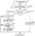
- control unit 41 determines the validity period of the local database stored in the storage unit 47 (step S54).
- step S54 when it is determined that the validity period of the local database has already passed and the local database cannot be used for the content specifying process (No), the control unit 41 sets each circuit block to update the local database. Control is performed (step S55). Details of the local database update processing will be described later. In step S54, for example, when it is determined that the content in the local database has been broadcast in the past, “No” is selected.
- the local database may be configured to be updated when the video receiving device 40 is turned on, turned off, or when the reception channel is switched.
- step S51 When it is determined in step S51 that the local database is not stored in the storage unit 47 (No), the local matching process is not performed, and the process proceeds to step S42 in FIG. At this time, in step S42, it is determined that the content specifying process is not successful (No).
- step S51 when it is determined that the local database is not stored in the storage unit 47 (No), the process may proceed to step S55 to newly acquire the local database.
- step S54 If it is determined in step S54 that the local database is within the valid period and the local database can be used for content identification processing (Yes), the local database is not updated, and the process proceeds to step S42 in FIG. To do.
- step S42 a determination is made based on the result of the local matching process performed in step S52.
- step S56 the control unit 41 instructs the video recognition unit 66 to perform online matching processing, and the video recognition unit 66 performs online matching processing based on the instruction (step S53). .
- step S53 the control unit 41 sends the fingerprint (terminal video recognition information) generated in step S50 to the video recognition device 20 to request content identification processing (content identification processing based on the video recognition processing). Control each circuit block. In addition, each circuit block is controlled so that the analysis information transmitted from the video recognition apparatus 20 as a result of the online matching process is received and stored in the storage unit 47. Details of the online matching process will be described later.
- step S53 When the online matching process in step S53 is completed, the process proceeds to step S42 in FIG.
- step S42 a determination is made based on the result of the online matching process performed in step S53.
- step S52 the local matching process in step S52 will be described.
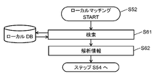
- FIG. 7 is a flowchart schematically showing the operation of the local matching process performed by the video reception device 40 in the first embodiment.
- the video recognition unit 66 of the video reception device 40 uses the fingerprint (terminal video recognition information) generated from the partial video in step S50 in order to identify the content corresponding to the partial video by local matching processing.
- the image recognition processing is performed by collating with the fingerprint (server image recognition information) included in the local database stored in the storage unit 47, and the server image recognition information matching the terminal image recognition information is searched (step S61).
- the video recognition unit 66 performs these operations while giving an instruction to the control unit 41 to perform control necessary for collation.
- the video recognition unit 66 may operate to search for server video recognition information whose similarity to the terminal video recognition information is equal to or higher than a predetermined numerical value (for example, 60%).
- step S61 if the server video recognition information matching the terminal video recognition information can be found from the local database, the video recognition unit 66 stores the analysis information associated with the content corresponding to the server video recognition information in the storage unit 47 ( The data is read from the local database and output to the control unit 41 (step S62).
- the content identification process (content identification process based on the video recognition process) of the fingerprint (terminal video recognition information) generated from the partial video is performed.
- step S61 When it is determined in step S61 that there is no server video recognition information matching the terminal video recognition information in the local database (or there is only server video recognition information whose similarity with the terminal video recognition information is less than a predetermined value).
- step S62 information indicating that the content specifying process has not been successful (for example, “NG”, “0”, etc.) is output to the control unit 41 as analysis information.
- step S53 the online matching process in step S53 will be described.
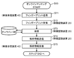
- FIG. 8 is a flowchart schematically showing the operation of online matching processing performed by the video reception device 40 and the video recognition device 20 in the first embodiment.
- the video recognition unit 66 of the video receiver 40 uses the fingerprint (terminal video recognition information) generated from the partial video in step S50 together with the video recognition request to identify the content corresponding to the partial video by online matching processing.
- the control unit 41 is instructed to transmit to the recognition device 20 (step S71).
- control unit 41 controls each circuit block so as to transmit the terminal image recognition information and the image recognition request to the image recognition device 20.
- the video recognition device 20 receives a fingerprint (terminal video recognition information) and a video recognition request transmitted from the video reception device 40 via the communication network 16 (step S72).
- the search unit 22 of the video recognition device 20 uses the terminal video recognition information received in step S72 as a finger of an online database (abbreviated as “online DB” in the drawing) stored in the storage unit 23 of the video recognition device 20.
- the image recognition processing is performed by collating with the print (server image recognition information), and the server image recognition information matching the terminal image recognition information is searched (step S73).
- the video recognition device 20 may operate to search for server video recognition information whose similarity to the terminal video recognition information is a predetermined numerical value (for example, 60%) or more.
- step S73 if the server video recognition information matching the terminal video recognition information can be found from the online database, the search unit 22 specifies the content corresponding to the server video recognition information (content specifying process), The associated analysis information is read from the storage unit 23 (online database) and transmitted to the video reception device 40 (step S74).
- the content identification process (content identification process based on the video recognition process) of the fingerprint (terminal video recognition information) generated from the partial video is performed.
- step S73 When it is determined in step S73 that there is no server video recognition information matching the terminal video recognition information in the online database (or there is only server video recognition information whose similarity with the terminal video recognition information is less than a predetermined value).
- step S74 information indicating that the content specifying process was not successful (for example, “NG”, “0”, etc.) is transmitted as analysis information to the video receiver 40.
- the control unit 41 of the video reception device 40 controls each circuit block so that the analysis information is received and stored in the storage unit 47 (step S75).
- step S55 the local database update process in step S55 will be described.
- the local database stored in the storage unit 47 is updated as follows.
- the video receiving device 40 is a viewing history stored in the storage unit 47 of the video receiving device 40 (stored in the storage unit 23 of the video recognizing device 20 and acquired by the video receiving device 40 from the video recognizing device 20. Based on the (viewing history), a time zone and a channel (or content) likely to be viewed next by the video receiving device 40 are predicted. This channel may be a channel selected by the user in the video transmission device such as the STB 14 or may be a channel selected by a tuner included in the video reception device 40. This prediction is transmitted from the video receiving device 40 to the video recognition device 20, and the video recognition device 20 has a fingerprint (server video recognition information) and analysis information associated with the predicted time zone and channel (or content). Generate a local database from an online database. The local database is transmitted from the video recognition device 20 to the video reception device 40 and stored in the storage unit 47 of the video reception device 40. Thus, the local database is updated.
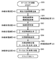
- FIG. 9 is a flowchart schematically showing an operation of local database update processing performed by the video reception device 40 and the video recognition device 20 in the first embodiment.
- the control unit 41 of the video reception device 40 controls each circuit block so as to transmit the current viewing information (for example, the current viewing channel and the viewing start time) to the video recognition device 20 (step S80).
- the current viewing information for example, the current viewing channel and the viewing start time
- the video recognition device 20 receives the current viewing information transmitted from the video receiving device 40, adds the received viewing information to the viewing history of the video receiving device 40 stored in the storage unit 23, and receives the video
- the viewing history of the device 40 is updated.
- this viewing history is information representing a history from the past to the present, such as the channel (or content) that has been viewed so far in the video reception device 40 and the date and time when the viewing was performed.
- the updated viewing history information is transmitted from the video recognition device 20 to the video reception device 40 (step S81).
- the video recognition device 20 can grasp the viewing status of the video reception device 40 by the content identification processing based on the fingerprint (terminal video recognition information) transmitted from the video reception device 40, and as a result of the content identification processing. Based on the above, the viewing history of the video receiving device 40 stored in the storage unit 23 may be updated.
- the control unit 41 of the video reception device 40 controls each circuit block so as to receive the viewing history information transmitted from the video recognition device 20 and store it in the storage unit 47 (step S82).
- the viewing history for the past five weeks or more from the current time is stored in the storage unit 23 of the video recognition device 20, and the viewing history information for at least the past five weeks from the current time is stored in the video recognition device 20. Is transmitted to the video receiving device 40 and stored in the storage unit 47 of the video receiving device 40.
- the viewing history storage period may be appropriately set according to the specifications of the additional information display system 10. desirable.
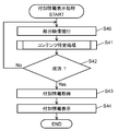
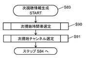
- the video recognition unit 66 of the video receiving device 40 generates next viewing information, which is local database generation information, based on the viewing history information and the current viewing information stored in the storage unit 47 (step S83).
- the next viewing information is information including information on a channel and a time zone expected to be viewed next time. The next viewing information generation process will be described later.
- the generated next viewing information is transmitted from the video receiving device 40 to the video recognizing device 20 (step S84). That is, the above-mentioned “prediction” is the next viewing information.
- the video recognition device 20 receives the next viewing information transmitted from the video receiving device 40 and searches the online database based on the information included in the received next viewing information. If the content corresponding to the information included in the next viewing information (channel and time zone information predicted to be viewed next time) can be found from the online database, the video recognition device 20 prints the fingerprint (server) A local database having image recognition information) and analysis information is generated. This analysis information may include program meta information such as an electronic program guide. Then, the video recognition device 20 transmits the generated local database to the video reception device 40 through the communication network 16 (step S85).
- the control unit 41 of the video reception device 40 controls each circuit block so as to receive the local database transmitted from the video recognition device 20 and store it in the storage unit 47 (step S86). In this way, the local database in the storage unit 47 is updated.
- the flowchart shown in FIG. 6 shows a configuration in which the local database update processing is performed after the local matching processing, but the present embodiment is not limited to this configuration.
- the local database update process may be performed, for example, immediately after the video receiver 40 is turned on, or may be performed when the channel is switched.
- the video receiving device 40 may be provided with a backup power source, and after the video receiving device 40 is turned off, the backup power source may be used to update the local database.
- the backup power source may be used to update the local database.
- step S83 Next, the next viewing information generation process in step S83 will be described.
- the video recognition unit 66 of the video receiving device 40 grasps the viewing tendency of the user based on the past viewing history and the current viewing information (channel that the user is viewing), and the user next views. Predict time zones and channels.
- the next viewing information includes information on the predicted time zone and channel.
- FIG. 10 is a flowchart schematically showing the operation of the next viewing information generation process performed by the video reception device 40 in the first embodiment.
- the video recognition unit 66 selects the “next viewing time zone” (step S90).
- the next viewing time zone is a time zone during which the user is expected to view the content next time. Details of the next viewing time zone selection process will be described later.
- the video recognition unit 66 selects “next viewing channel” (step S91).
- the next viewing channel is a channel predicted to be viewed next by the user. Details of the next viewing channel selection process will be described later.
- the video reception device 40 generates next viewing information including the next viewing time zone information selected in step S90 and the next viewing channel information selected in step S91.
- the video recognition device 20 When the next viewing information is transmitted from the video receiving device 40 to the video recognition device 20, the video recognition device 20 generates a local database based on the next viewing information. Then, the generated local database is transmitted from the video recognition device 20 to the video reception device 40, so that the video reception device 40 can acquire and update the local database.
- step S90 the process for selecting the next viewing time zone in step S90 will be described.
- the video recognition unit 66 of the video receiver 40 divides one day (24 hours) into a plurality of time zones, and a predetermined period (for example, one week) after the time zone to which the current time belongs (denoted as “current time zone”). ) Is calculated in each time zone, and the time zone having the highest “next viewing time zone likelihood” is selected as the “next viewing time zone”.
- the next viewing time zone likelihood is a numerical value of the possibility that the user will view in the time zone.
- the formula for calculating the next viewing time zone likelihood is set so that the numerical value increases in the time zone in which the user is more likely to watch.
- the next viewing time zone likelihood is calculated to predict and select the next time zone (next viewing time zone) in which the user will watch.
- the video recognizing unit 66 quantifies the time difference between the current time and each time zone, the past viewing frequency and viewing habits in each time zone, whether or not there is a recording reservation (viewing reservation), and the like based on these numerical values. Calculate the time zone likelihood. The next viewing time zone likelihood increases in the time zone closer to the current time, increases in the time zone in the past where the viewing frequency is high and there is a viewing habit, and the time zone in which there is a recording reservation (or viewing reservation) The value is set to be large.
- FIG. 11 is a flowchart schematically showing the operation of the next viewing time zone selection process performed by the video reception device 40 in the first embodiment.
- the image recognizing unit 66 divides one day (24 hours) into a plurality of time zones, and one time zone within a predetermined period (for example, one week) from the time zone (current time zone) to which the current time belongs. Is selected, and the time zone is set as the next viewing time zone likelihood calculation target time zone (step S100).
- the calculation target time zone of the next viewing time zone likelihood is abbreviated as “likelihood calculation target time zone”.
- this predetermined period that is, the period for calculating the next viewing time zone likelihood is not limited to one week, and may be one week or more, or may be less than one week. It is desirable that this predetermined period is appropriately set according to the specifications of the additional information display system 10.
- the video recognition unit 66 calculates a “time interval” based on the time difference between the current time and the likelihood calculation target time zone (step S101).
- the “time interval” is a numerical value calculated based on the time difference between the current time and the likelihood calculation target time zone and a predetermined weighting factor ( ⁇ ). The smaller the time difference, the larger the numerical value. It is set to be. A specific calculation example of the “time interval” will be described later.
- the video recognition unit 66 calculates “viewing frequency” in the likelihood calculation target time zone based on the viewing history stored in the storage unit 47 (step S102).
- the “viewing frequency” is a numerical value calculated based on the “first viewing number” and a predetermined weighting coefficient ( ⁇ ), and the larger the “first viewing number”, the larger the numerical value.
- the “first number of viewing times” refers to the likelihood of the same day of the week as the day of the week to which the likelihood calculation target time period belongs in a predetermined past period that is the search range of the viewing history for calculating the next viewing time period likelihood. This is a numerical value indicating how many times the user has viewed in the same time zone as the degree calculation target time zone.
- the predetermined past period is set to 5 weeks, and the next viewing time zone likelihood is set to be calculated based on the viewing history of the past 5 weeks from the current time zone.
- the video recognition unit 66 refers to the viewing history stored in the storage unit 47, and for each Monday of the past 5 weeks from the current time zone.
- the presence / absence of viewing in the time zone from 20:00 to 24:00 is checked to calculate the “first viewing count”. If there are viewing histories in the time zone from 20:00 to 24:00 on each Monday of the past five weeks, the “first viewing count” is “5”.
- the “first viewing frequency” is multiplied by a predetermined weighting coefficient ( ⁇ ) to calculate “viewing frequency”. A specific calculation example of “viewing frequency” will be described later.
- the video recognition unit 66 calculates the “viewing customs” in the likelihood calculation target time zone based on the viewing history stored in the storage unit 47 (step S103).
- This “viewing customs” refers to the degree to which the user views in the same time zone as the likelihood calculation target time zone on the same day of the week to which the likelihood calculation target time zone belongs in a predetermined past period. It is a numerical value that represents whether or not it has been performed, and is set so that the higher the habit, the larger the numerical value.
- the video recognition unit 66 calculates a “standard deviation” based on the viewing history and the likelihood calculation target time zone stored in the storage unit 47, and based on the “standard deviation” and a predetermined weight coefficient ( ⁇ ). Calculate “viewing customs”. A specific calculation example of the “viewing custom degree” will be described later.
- the video recognition unit 66 confirms whether or not there is a recording reservation (or viewing reservation) in the likelihood calculation target time zone, and digitizes the result of the confirmation based on a predetermined weighting coefficient ( ⁇ ) (step S104).
- this numerical value is referred to as “first reservation status”.
- a specific calculation example of the “first reservation status” will be described later.
- the video recognition unit 66 calculates the “time interval” calculated in step S101, the “viewing frequency” calculated in step S102, the “viewing convention” calculated in step S103, and the “viewing customs” calculated in step S104. From the “first reservation situation”, the “next viewing time zone likelihood” in the likelihood calculation target time zone set in step S100 is calculated (step S105). The “next viewing time zone likelihood” calculated here is stored in the storage unit 47 so as to know which time zone is calculated. A specific calculation example of the “next viewing time zone likelihood” will be described later.
- the video recognition unit 66 determines whether or not the next viewing time zone likelihood has been calculated in all the time zones of the predetermined period (step S106).
- step S106 When it is determined in step S106 that there is a time zone in which the next viewing time zone likelihood is not calculated within the predetermined period (No), the video recognition unit 66 returns to step S100 to return to the next viewing time zone.
- a time zone in which the likelihood is not calculated is set as a new likelihood calculation target time zone, and the above-described series of operations is repeated.
- step S106 When it is determined in step S106 that the next viewing time zone likelihood has been calculated in all time zones within the predetermined period (Yes), the video recognition unit 66 has completed the next viewing time zone likelihood. The degrees are compared with each other, and the time zone with the highest likelihood of the next viewing time zone is selected as the “next viewing time zone” (step S107).
- Step S101 for calculating “time interval”, step S102 for calculating “viewing frequency”, step S103 for calculating “viewing custom”, and step S104 for calculating “first reservation status” are not limited to this order, and may be performed in any order.
- the search range of the viewing history for calculating the predetermined past period that is, the likelihood of the next viewing time zone is not limited to 5 weeks, and may be 5 weeks or more, and less than 5 weeks. It may be. It is desirable that the predetermined past period is appropriately set according to the specifications of the additional information display system 10.
- FIG. 12 is a schematic diagram schematically illustrating an example of the operation of the next viewing time zone selection process performed by the video reception device 40 according to the first embodiment.
- 24 hours are divided into 6 time zones every 4 hours from the first time zone to the sixth time zone, and each time zone is divided into 0:00 to 4:00 (first time zone), 4 : 8:00 to 8:00 (second time zone), 8:00 to 12:00 (third time zone), 12:00 to 16:00 (fourth time zone), 16:00 to 20:00 (first time zone) 5 hours) and 20:00 to 24:00 (sixth time zone).
- this week is the 10th week
- the current time zone is the sixth Sunday time zone (20: 00-24: 00) of the 10th week.
- the search range of the viewing history for calculating a predetermined past period that is, the next viewing time zone likelihood is 5 weeks, and the past 5 weeks (the 5th week from the current time zone).
- the next viewing time zone likelihood is set to be calculated based on the viewing history (from Sunday 6th time zone to 10th week Sunday 5th time zone).
- viewing history information for at least the past five weeks from the current time is acquired from the video recognition device 20 and stored in the storage unit 47 of the video reception device 40.
- the predetermined period which is the target period for calculating the next viewing time zone likelihood, is 1 week, and the following week from the current time zone (Month of the 10th week from the first time zone to the 11th week) (Until Sunday's 6th time zone) is set as a target for calculating the next viewing time zone likelihood.
- all time zones within the calculation target period are sequentially set as likelihood calculation target time zones, and the next viewing time zone likelihood is calculated in each time zone, but here, as an example, , Time zone A (Month 6th time zone of 10th week), time zone B (Third time zone of Tuesday of 10th week), time zone C (10th week of Wednesday 5th time zone), time zone D ( An example in which four time zones (second time zone on Friday of the 10th week) are set as likelihood calculation target time zones and the next viewing time zone likelihood is calculated in those time zones will be described.
- FIG. 13 is a diagram showing an example of the next viewing time zone likelihood calculated by the video recognition unit 66 of the video receiving device 40 in the first embodiment.
- FIG. 13 shows “time interval” calculated in step S101 and “viewing frequency” calculated in step S102 for each of the time zones A, B, C, and D shown in FIG.
- FIG. 4 shows an example of calculated values of “viewing customs” calculated in step S103, “first reservation status” calculated in step S104, and “next viewing time zone likelihood” calculated in step S105.
- the video recognition unit 66 calculates the “time interval” described in step S101 by the following equation.
- the weighting factor ⁇ is 4 is shown.
- Time interval ⁇ ⁇ predetermined period / (time difference between likelihood calculation target time zone and current time)
- a predetermined period is converted into time.
- time zone C is 68 hours
- time zone D is 104 hours. Therefore, for example, the “time interval” of the time zone A is as follows.
- time zone B 18.67
- time zone C 9.88
- time zone D 6.46
- a difference between the start time of the current time zone and the start time of the likelihood calculation target time zone may be used.
- the video recognition unit 66 calculates the “viewing frequency” described in step S102 by the following equation.
- the weight coefficient ⁇ is set to 3 is shown.
- the “first viewing number” means that in the viewing history search range (predetermined past period), in the same time zone as the likelihood calculation target time zone on the same day of the week to which the likelihood calculation target time zone belongs, This is a numerical value indicating how many times the user has viewed (whichever channel is acceptable).
- the “first viewing count” regarding the time slot A is the sum of the viewing counts in the sixth time slot on each Monday from the fifth week to the ninth week.
- the “first viewing number” is the sum of the number of viewings in the third time zone of each Tuesday from the fifth week to the ninth week.
- the “first viewing count” is 5 in time zone A, 3 in time zone B, 3 in time zone C, and 5 in time zone D. Therefore, for example, the “viewing frequency” in the time zone A is as follows.
- the time zone B is 9
- the time zone C is 9
- the time zone D is 15.
- the video recognizing unit 66 calculates the “viewing custom” described in step S103 by the following formula 1.
- the weighting coefficient ⁇ is 3 is shown.
- the unit of each numerical value in Formula 1 is “week”.
- F is “viewing customs”.
- Ta is an average viewing interval in the same time zone as the likelihood calculation target time zone in the viewing history search range. For example, in the example shown in FIG. 12, if the likelihood calculation target time zone is time zone A, viewing is performed in the sixth time zone of each Monday from the fifth week to the ninth week.
- T2 is a time difference between the same time zone in which the previous viewing was performed and the same time zone in which the viewing was performed twice before, regarding the likelihood calculation target time zone.
- T2 3.
- T3 is a time difference between the same time zone in which viewing was performed twice before and the same time zone in which viewing was performed three times before, regarding the likelihood calculation target time zone.
- the viewing customs F regarding the time zone A is as follows.
- the viewing customs F regarding the time zone B is as follows.
- the video recognition unit 66 calculates the “first reservation status” described in step S104 by the following equation.
- the weighting factor ⁇ is set to 5 is shown.
- First reservation status ⁇ ⁇ presence / absence of recording reservation (or viewing reservation) in the likelihood calculation target time zone
- 1 is substituted if there is a reservation
- 0 is substituted if there is no reservation.
- Each “reservation status” is 0.
- the video recognition unit 66 calculates the “next viewing time zone likelihood” described in step S105 by the following equation.
- Next viewing time zone likelihood time interval + viewing frequency + viewing custom degree + first reservation status
- the “next viewing time zone likelihood” of time zone A is as follows: become.
- the “next viewing time zone likelihood” of another time zone is calculated, as shown in FIG. 13, it is 29.36 in time zone B, 21.88 in time zone C, and 24.46 in time zone D. .
- the video recognition unit 66 selects the time zone with the highest next viewing time zone likelihood as the “next viewing time zone”.
- the value of “next viewing time zone likelihood” in time zone A is the largest. Therefore, the video recognition unit 66 predicts the time zone A as the time zone most likely to be viewed next, and selects it as the “next viewing time zone”.
- each setting value listed here is merely an example, and in the present embodiment, each setting value is not limited to the numerical values described above.
- Each set value is desirably set optimally according to the specifications of the additional information display system 10.
- step S91 Next, the next viewing channel selection process in step S91 will be described.
- the video recognizing unit 66 of the video receiving device 40 calculates “next viewing channel likelihood” for each channel for all receivable channels in the “next viewing time zone” selected in step S90.
- the channel with the highest likelihood is selected as the “next viewing channel”.
- the next viewing channel likelihood is a numerical value of the possibility that the user views the channel.
- the calculation formula of the next viewing channel likelihood is set so that the numerical value becomes larger as the channel is more likely to be viewed by the user. In the present embodiment, by calculating the next viewing channel likelihood, a channel (next viewing channel) that the user views in the next viewing time zone is predicted and selected.
- the video recognition unit 66 quantifies the number of viewing times of each channel, the presence or absence of recording reservation (viewing reservation), and the like, and calculates the next viewing channel likelihood based on the numerical values.
- the value of the next viewing channel likelihood increases as the number of past viewing times increases, and increases as the channel has a recording reservation (or viewing reservation) in the next viewing time zone.
- FIG. 14 is a flowchart schematically showing the operation of the next viewing channel selection process performed by the video reception device 40 in the first embodiment.
- the video recognition unit 66 selects one of the receivable channels, and sets that channel as a channel to be calculated for the next viewing channel likelihood (step S110).
- the calculation target channel of the next viewing channel likelihood is abbreviated as “likelihood calculation target channel”.
- the video recognition unit 66 calculates the “occupancy ratio” of the likelihood calculation target channel in the next viewing time zone selected in step S90 (step S111).
- the “occupancy ratio” is a numerical value calculated based on the “viewing history search range”, the “second viewing count”, and a predetermined weighting coefficient ( ⁇ ), and the “second viewing count” is The number is set to increase as the number increases.
- This “second viewing count” is used in the same time zone as the next viewing time zone on the same day as the day to which the next viewing time zone belongs in the search range of the viewing history (the above-mentioned predetermined past period). It is a numerical value that represents how many times the likelihood calculation target channel has been viewed by a person.
- the time zone from 20:00 to 24:00 on Monday of this week is selected as the next viewing time zone
- the fifth channel is set as the likelihood calculation target channel
- the viewing history search range (predetermined past period) Is set to 5 weeks
- the next viewing channel likelihood is set to be calculated based on the viewing history of the past 5 weeks from the current time zone.
- the video recognizing unit 66 refers to the viewing history stored in the storage unit 47 and views the fifth channel in the time zone from 20:00 to 24:00 on each Monday of the past 5 weeks from the current time zone.
- the “second viewing count” is calculated by checking the presence / absence of the “second viewing count”, and the “occupancy ratio” is calculated based on the “second viewing count”. A specific calculation example of “occupancy” will be described later.
- the video recognition unit 66 confirms whether or not there is a recording reservation (or viewing reservation) in the next viewing time period, and digitizes the result of the confirmation based on a predetermined weight coefficient ( ⁇ ) (step S112).
- This numerical value is referred to as “second reservation status”. A specific calculation example of the “second reservation status” will be described later.
- the video recognition unit 66 calculates “next viewing” in the likelihood calculation target channel set in step S110 from the “occupancy ratio” calculated in step S111 and the “second reservation status” calculated in step S112. “Channel likelihood” is calculated (step S113).
- the “next viewing channel likelihood” calculated here is stored in the storage unit 47 so as to know which channel has been calculated. A specific calculation example of “next viewing channel likelihood” will be described later.
- the video recognition unit 66 determines whether or not the calculation of the next viewing channel likelihood in the next viewing time zone has been completed for all receivable channels (step S114).
- step S114 When it is determined in step S114 that there is a channel for which the next viewing channel likelihood has not been calculated (No), the video recognition unit 66 returns to step S110 and the channel for which the next viewing channel likelihood has not been calculated. Is set as a new likelihood calculation target channel, and the above-described series of operations is repeated.
- step S114 If it is determined in step S114 that the next viewing channel likelihood has been calculated for all receivable channels (Yes), the video recognition unit 66 compares the calculated next viewing channel likelihoods with each other. Then, the channel having the highest likelihood of the next viewing channel is selected as the “next viewing channel” (step S115).
- FIG. 15 is a schematic diagram schematically showing an example of the operation of the next viewing channel selection process performed by the video reception device 40 in the first embodiment.
- time zone A (Monday of the 10th week from 20:00 to 24:00) is selected as the “next viewing time zone”, and five channels from the first channel to the fifth channel of time zone A are selected.
- the example which performs the next viewing channel selection process regarding is shown.
- the search history search range for calculating the next viewing channel likelihood that is, the next viewing channel likelihood is set to 5 weeks, and the next based on the viewing history of the past 5 weeks from the current time zone. It is set to calculate the viewing channel likelihood.
- viewing history information for at least the past five weeks from the current time is acquired from the video recognition device 20 and stored in the storage unit 47 of the video reception device 40.
- FIG. 16 is a diagram showing an example of the next viewing channel likelihood calculated by the video recognition unit 66 of the video receiving device 40 in the first embodiment.
- step S111 “occupancy ratio” calculated in step S111 and “calculated in step S112” for each of the first channel, the second channel, the third channel, the fourth channel, and the fifth channel shown in FIG.
- An example of each calculated value of “second reservation status” and “next viewing channel likelihood” calculated in step S113 is shown.
- the video recognition unit 66 calculates the “occupancy ratio” described in step S111 by the following equation.
- the weighting coefficient ⁇ is 5 is shown.
- Occupancy ⁇ ⁇ (second view count of likelihood calculation target channel + 1) / (viewing history search range + 1)
- the “second viewing number” means that in the viewing history search range (the past five weeks in the example shown in FIG. 15), in the same time zone as the next viewing time zone on the same day of the week as the next viewing time zone belongs. It is a numerical value indicating how many times the user has viewed the likelihood calculation target channel.
- the “second view count” for the fifth channel is the sum of the view counts for the fifth channel from 20:00 to 24:00 on each Monday from the fifth week to the ninth week. Since viewing is performed in the same time zone of the fifth week, the eighth week, and the ninth week, it becomes 3. Therefore, for example, the “occupancy ratio” of the fifth channel in the time zone A selected as the “next viewing time zone” is as follows.
- the “occupancy ratio” of other channels is calculated, as shown in FIG. 16, the first channel is 0.83, the second channel is 2.50, the third channel is 0.83, and the fourth channel is 0.83.
- the video recognition unit 66 calculates the “second reservation status” described in step S112 by the following equation.
- the weighting coefficient ⁇ is 3 is shown.
- Second reservation situation ⁇ ⁇ presence or absence of recording reservation (or viewing reservation) in the next viewing time zone
- 1 is substituted if there is a reservation
- 0 is substituted if there is no reservation.
- the “second reservation status” of each channel is 0 as shown in FIG.
- the video recognition unit 66 calculates the “next viewing channel likelihood” described in step S113 by the following equation.
- Next viewing channel likelihood occupancy rate + second reservation status
- the “next viewing channel likelihood” of the fifth channel is as follows.
- the “next viewing channel likelihood” of other channels is calculated, as shown in FIG. 16, the first channel is 0.83, the second channel is 2.50, the third channel is 0.83, For 4 channels, it is 0.83.
- the video recognition unit 66 selects the channel having the highest next viewing channel likelihood as the “next viewing channel”.
- the numerical value of the “next viewing channel likelihood” of the fifth channel is the largest. Therefore, the video recognition unit 66 predicts the fifth channel as the channel most likely to be viewed next, and selects it as the “next viewing channel”.
- the information of the next viewing channel is transmitted from the video receiving device 40 to the video recognition device 20, and the video recognition device 20 generates a local database based on the information of the next viewing channel and transmits it to the video receiving device 40.
- each setting value listed here is merely an example, and in the present embodiment, each setting value is not limited to the numerical values described above.
- Each set value is desirably set optimally according to the specifications of the additional information display system 10.
- the video receiving device 40 is configured to transmit and receive data via the communication network 16, and includes the input unit 65, the video extracting unit 45, the storage unit 47, and the video recognition.
- Unit 66 and control unit 41 The input unit 65 is configured to input a video signal output from a video transmission device (for example, STB 14) installed outside.
- the video extraction unit 45 is configured to extract a partial video for video recognition processing from the video signal.
- the storage unit 47 is configured to store a local database generated based on the local database generation information in the video recognition device 20 connected to the communication network 16.
- the video recognition unit 66 generates second content recognition information (terminal video recognition information) from the partial video extracted by the video extraction unit 45, and sends the second content recognition information (terminal video recognition information) to the video recognition device 20.
- a local matching process for matching for matching.
- the control unit 41 controls the acquisition of the local database from the video recognition device 20 and is connected to the communication network 16 with additional information (for example, advertisement information) based on the online matching process result or the local matching process result. It is configured to perform control acquired from the additional information distribution device 30.
- the amount of data in the online database stored in the storage unit 23 of the video recognition device 20 is enormous. Therefore, in the online matching process, it is possible to perform a highly accurate content specifying process, but the second content recognition information (terminal video recognition information) transmitted from the video receiver 40 and the online database are stored in the storage unit 23. It takes time to collate with the stored first content recognition information (server video recognition information).
- the local database stored in the storage unit 47 of the video reception device 40 is generated by the video recognition device 20 selecting from the online database, so that the data amount is smaller than that of the online database. That is, the local matching process performed using the local database can be completed in a shorter time than the online matching process.
- the video reception device 40 selectively (or both) performs the local matching processing and the online matching processing, so that the content specifying processing (video recognition processing) regarding the video signal input from the video transmission device such as the STB 14 is performed. It is possible to perform the content specifying process based on the above with high accuracy while reducing the time.
- the video receiver 40 can acquire additional information based on the result of the online matching process or the local matching process from the additional information distribution apparatus 30 and superimpose it on the video signal.
- the video receiving device 40 may include a display unit 54 configured to display a video in which the additional information 51 is superimposed on the video signal.
- the video recognition unit 66 of the video reception device 40 is configured to generate next viewing information based on the viewing history stored in the storage unit 47, and the control unit 41 uses the next viewing information as local database generation information. You may be comprised so that control which transmits to a video recognition apparatus may be performed.
- the video recognition unit 66 of the video reception device 40 is configured to generate the next viewing information by predicting a time zone and a channel to be viewed next based on the viewing history stored in the storage unit 47. It may be.
- the video recognition apparatus 20 can use the next viewing information as the local database generation information, so that it is possible to generate a local database related to content with a relatively high probability of viewing by the user. Therefore, the video receiver 40 can perform highly accurate local matching processing by using this local database.
- control unit 41 of the video reception device 40 may be configured to receive and store the viewing history information generated and transmitted by the video recognition device 20 in the storage unit 47.
- the first embodiment has been described as an example of the technique disclosed in the present application.
- the technology in the present disclosure is not limited to this, and can also be applied to embodiments in which changes, replacements, additions, omissions, and the like are performed.
- Embodiment 1 the example in which the video reception device 40 operates to perform either one of the local matching process or the online matching process has been described with reference to FIG. However, the video receiving device 40 performs both the local matching process and the online matching process as shown in FIG. 17 instead of the operation shown in FIG. It may be configured.
- FIG. 17 is a flowchart schematically showing the operation of the content specifying process performed by the video reception device 40 in another embodiment.
- steps having substantially the same operation as the steps shown in FIG. 6 are given the same reference numerals as those shown in FIG. 6, and detailed descriptions thereof are omitted.
- the video recognition unit 66 first generates a fingerprint (terminal video recognition information) from the partial video extracted by the video extraction unit 45, similarly to step S50 shown in FIG. S50).
- control unit 41 determines whether or not the local database is stored in the storage unit 47, as in step S51 shown in FIG.
- the local database is abbreviated as “local DB” (step S51).
- step S51 When it is determined in step S51 that the local database is stored in the storage unit 47 (Yes), the control unit 41 performs local matching processing in the video recognition unit 66 in the same manner as in step S52 illustrated in FIG.
- the image recognition unit 66 performs local matching processing based on the instruction (step S52).
- step S51 When it is determined in step S51 that the local database is not stored in the storage unit 47 (No), or after the end of step S52, the control unit 41 displays the video as in step S53 shown in FIG.
- the recognizing unit 66 is instructed to perform online matching processing, and the video recognizing unit 66 performs online matching processing based on the instruction (step S53).
- control unit 41 determines the validity period of the local database stored in the storage unit 47 as in step S54 shown in FIG. 6 (step S54).
- step S54 If it is determined in step S54 that the validity period of the local database has already passed and the local database cannot be used for the content specifying process (No), the control unit 41 performs the same process as in step S55 shown in FIG. Then, each circuit block is controlled to update the local database (step S55).
- step S54 If it is determined in step S54 that the local database is within the valid period and the local database can be used for content identification processing (Yes), the control unit 41 does not update the local database.
- the video recognition unit 66 selects one of the result of the local matching process and the result of the online matching process (step S57), and proceeds to step S42 in FIG.
- step S57 the video recognition unit 66 selects the matching result when the result of the local matching process matches the result of the online matching process, and selects the result that the video recognition process has failed when they do not match. May be.
- the video recognition unit 66 may operate so as to select the result of the online matching process when the result of the local matching process and the result of the online matching process do not match.
- the video receiving apparatus 40 configured as described above can improve the accuracy of the video recognition process by performing both the local matching process and the online matching process.
- the local matching process may be performed after the online matching process.
- FIG. 18 is a flowchart schematically showing an example of the operation of local database update processing performed by the video reception device 40 and the video recognition device 20 according to another embodiment.
- steps having substantially the same operation as the steps shown in FIG. 9 are given the same reference numerals as those shown in FIG. 9, and detailed descriptions thereof are omitted.
- the current viewing information of the video receiving device 40 is added to the viewing history of the video receiving device 40 stored in the storage unit 47, and the viewing history of the video receiving device 40 is updated.
- the video recognition unit 66 generates next viewing information based on the viewing history information and the current viewing information stored in the storage unit 47, as in step S83 shown in FIG.
- the generated next viewing information is transmitted from the video receiving device 40 to the video recognizing device 20 as in step S84 shown in FIG. 9 (step S87).
- the video recognition device 20 generates a local database based on the next viewing information transmitted from the video reception device 40 and transmits it to the video reception device 40 in the same manner as in step S85 shown in FIG. 9 (step S85).
- the control unit 41 of the video reception device 40 controls each circuit block so as to receive the local database transmitted from the video recognition device 20 and store it in the storage unit 47, similarly to step S86 shown in FIG. (Step S86), the process proceeds to Step S42 in FIG.
- the local database in the storage unit 47 may be updated.
- the local database is updated based on the viewing history stored in the storage unit 47 of the video receiving device 40. Therefore, compared with the method shown in FIG. 9, the time required for updating the local database can be shortened. Can do.
- FIG. 19 is a flowchart schematically showing another example of the operation of local database update processing performed by the video reception device 40 and the video recognition device 20 in another embodiment.
- steps having substantially the same operation as the steps shown in FIG. 9 are given the same reference numerals as those shown in FIG. 9, and detailed descriptions thereof are omitted.
- the local database is updated based on the high audience rating program information.
- the control unit 41 of the video receiving device 40 transmits the high audience rating program information to the video recognition device 20, and instructs the video recognition device 20 to generate a local database based on the high audience rating program information (step S88).
- the high audience rating program information is, for example, information indicating content with many opportunities to be subjected to content identification processing.
- the video reception device 40 may generate the high audience rating program information by accumulating the results of the past content specifying process, and acquire the high audience rating program information supplied from the outside via the communication network 16. May be.
- the video receiving device 40 may instruct the video recognition device 20 to acquire high audience rating program information via the communication network 16 and generate a local database based on the high audience rating program information.
- control unit 41 of the video reception device 40 may be configured to instruct the video recognition device 20 to use the high audience rating program information as the local database generation information.
- the video recognition device 20 generates a local database based on the high audience rating program information transmitted from the video reception device 40 and transmits it to the video reception device 40 (step S89). Note that the operation of the video recognition apparatus 20 in step S89 is substantially the same as step S85 shown in FIG. 9 except that the next viewing information is replaced with the high audience rating program information.
- the control unit 41 of the video reception device 40 controls each circuit block so as to receive the local database transmitted from the video recognition device 20 and store it in the storage unit 47, similarly to step S86 shown in FIG. (Step S86), the process proceeds to Step S42 in FIG.
- the local database in the storage unit 47 may be updated.
- the video recognition apparatus 20 can generate a local database related to content with a high audience rating. Therefore, the video receiver 40 can perform highly accurate local matching processing by using this local database.
- the configuration in which the video receiving device 40 includes the display unit 54 has been described.
- the video receiving device in the present embodiment is not limited to this configuration.
- the video receiving apparatus may not include the display unit.
- FIG. 20 is a block diagram schematically illustrating an example of the configuration of the video reception device 140 according to another embodiment.
- the video receiving apparatus 140 shown in FIG. 20 differs from the video receiving apparatus 40 shown in FIG. 3 in the first embodiment mainly in the following points.
- the video reception device 140 does not include the display unit 54, and the video output unit 144 is configured to output a video signal to the video display device 154 installed outside in a wired or wireless manner.
- the video output unit 144 superimposes the additional information on the video signal based on an instruction from the control unit 41, similarly to the video output unit 44 described in the first embodiment.
- a video reception device 140 for example, a video recording function, a broadcast signal reception function, a video signal input function, and a video signal output function are provided, and a video signal is transmitted to a video display device 154 installed outside.
- a recording apparatus configured as described above. Examples of such a recording apparatus include a hard disk recorder, a DVD recorder, and a BD recorder.
- FIG. 20 shows main circuit blocks related to the operation described in this embodiment, and functions and circuit blocks (for example, a video recording function) related to other operations are omitted.
- the same effect as that of the video receiving device 40 shown in the first embodiment can be obtained.
- each component shown in this embodiment may be configured by an independent dedicated circuit, or a program created so as to realize one or more of these operations is executed by a processor. It may be configured to execute.
- the program at this time may be acquired by downloading from a server or the like, or may be acquired via a predetermined recording medium (for example, an optical disk such as a CD-ROM, a magnetic disk, a semiconductor memory, or the like).
- each operation in the server shown in this embodiment may be centrally processed by a single server or may be distributedly processed by a plurality of servers.
- the present disclosure can be applied to a video reception device that can acquire additional information related to a video signal input from a video transmission device installed outside and superimpose the acquired additional information on the video signal.
- the present disclosure is applicable to a television receiver, a hard disk recorder, a DVD recorder, a BD recorder, and the like.
- Additional information display system 12 Broadcasting station 14 STB 16 Communication network 20 Video recognition device 21, 42 HTTP transmission / reception unit 22 Search unit 23, 47 Storage unit 30 Additional information distribution device 40, 140 Video reception device 41, 141 Control unit 43 Operation signal reception unit 44, 144 Video output unit 45 Video Extraction unit 46 Additional information display control unit 48 Video input unit 49 Reception unit 51 Additional information 54 Display unit 65 Input unit 66 Video recognition unit 81 Content 82, 84 Fingerprint 83 Analysis information 91 Video signal 154 Video display device
Abstract
Priority Applications (4)
| Application Number | Priority Date | Filing Date | Title |
|---|---|---|---|
| US14/888,449 US9906844B2 (en) | 2014-03-26 | 2014-07-16 | Video reception device, video recognition method and additional information display system |
| JP2015512961A JP6340596B2 (ja) | 2014-03-26 | 2014-07-16 | 映像受信装置、映像認識方法および付加情報表示システム |
| CN201480003481.XA CN105144735A (zh) | 2014-03-26 | 2014-07-16 | 影像接收装置、影像识别方法以及附加信息显示系统 |
| EP14841401.4A EP3125569A4 (fr) | 2014-03-26 | 2014-07-16 | Dispositif de réception vidéo, procédé de reconnaissance vidéo et système d'affichage d'informations supplémentaires |
Applications Claiming Priority (2)
| Application Number | Priority Date | Filing Date | Title |
|---|---|---|---|
| JP2014-063498 | 2014-03-26 | ||
| JP2014063498 | 2014-03-26 |
Publications (1)
| Publication Number | Publication Date |
|---|---|
| WO2015145493A1 true WO2015145493A1 (fr) | 2015-10-01 |
Family
ID=54194098
Family Applications (2)
| Application Number | Title | Priority Date | Filing Date |
|---|---|---|---|
| PCT/JP2014/003761 WO2015145492A1 (fr) | 2014-03-26 | 2014-07-16 | Dispositif de réception vidéo, procédé de reconnaissance vidéo et système d'affichage d'informations supplémentaires |
| PCT/JP2014/003762 WO2015145493A1 (fr) | 2014-03-26 | 2014-07-16 | Dispositif de réception vidéo, procédé de reconnaissance vidéo et système d'affichage d'informations supplémentaires |
Family Applications Before (1)
| Application Number | Title | Priority Date | Filing Date |
|---|---|---|---|
| PCT/JP2014/003761 WO2015145492A1 (fr) | 2014-03-26 | 2014-07-16 | Dispositif de réception vidéo, procédé de reconnaissance vidéo et système d'affichage d'informations supplémentaires |
Country Status (5)
| Country | Link |
|---|---|
| US (2) | US9906844B2 (fr) |
| EP (2) | EP3125568A4 (fr) |
| JP (2) | JP6340558B2 (fr) |
| CN (2) | CN105144735A (fr) |
| WO (2) | WO2015145492A1 (fr) |
Cited By (1)
| Publication number | Priority date | Publication date | Assignee | Title |
|---|---|---|---|---|
| JP2018064246A (ja) * | 2016-10-14 | 2018-04-19 | 学校法人立命館 | 情報記録装置、時刻特定装置、時刻特定システム、及び時刻特定方法 |
Families Citing this family (5)
| Publication number | Priority date | Publication date | Assignee | Title |
|---|---|---|---|---|
| KR102019493B1 (ko) * | 2015-02-09 | 2019-09-06 | 삼성전자주식회사 | 디스플레이 장치 및 그 정보 제공 방법 |
| KR20180037826A (ko) | 2016-10-05 | 2018-04-13 | 삼성전자주식회사 | 디스플레이 장치, 이의 제어 방법 및 정보 제공 시스템 |
| KR102384215B1 (ko) * | 2017-08-01 | 2022-04-07 | 삼성전자주식회사 | 전자 장치 및 그의 제어방법 |
| KR102569660B1 (ko) * | 2018-06-15 | 2023-08-25 | 삼성전자주식회사 | 디스플레이장치 및 그 제어방법 |
| TWI715166B (zh) * | 2019-08-27 | 2021-01-01 | 宏正自動科技股份有限公司 | 多螢幕控制系統 |
Citations (6)
| Publication number | Priority date | Publication date | Assignee | Title |
|---|---|---|---|---|
| JPH10214258A (ja) | 1997-01-28 | 1998-08-11 | Victor Co Of Japan Ltd | データ処理システム |
| JP2000287189A (ja) * | 1999-03-31 | 2000-10-13 | Toshiba Corp | テレビ番組の視聴管理装置 |
| JP2002209204A (ja) * | 2000-04-14 | 2002-07-26 | Nippon Telegr & Teleph Corp <Ntt> | 放送情報に関連した情報の取得方法及びシステム並びに装置 |
| JP2004007323A (ja) * | 2001-06-11 | 2004-01-08 | Matsushita Electric Ind Co Ltd | テレビジョン放送受信機 |
| JP2005347806A (ja) * | 2004-05-31 | 2005-12-15 | Toshiba Corp | 電子機器および該電子機器にて実行される番組情報取得方法 |
| JP2011034323A (ja) * | 2009-07-31 | 2011-02-17 | Nippon Telegr & Teleph Corp <Ntt> | 情報端末装置、情報検索方法、および情報検索プログラム |
Family Cites Families (102)
| Publication number | Priority date | Publication date | Assignee | Title |
|---|---|---|---|---|
| JPH04245552A (ja) | 1991-01-31 | 1992-09-02 | Canon Inc | データベース検索方法 |
| JPH09185720A (ja) | 1995-12-28 | 1997-07-15 | Canon Inc | 画像抽出装置 |
| JP3731952B2 (ja) | 1996-10-18 | 2006-01-05 | シャープ株式会社 | 動画像検索用情報生成装置 |
| JP3485020B2 (ja) | 1999-04-09 | 2004-01-13 | 日本電気株式会社 | 文字認識方法及び装置ならびに記憶媒体 |
| US8205223B2 (en) | 2000-04-12 | 2012-06-19 | Lg Electronics Inc. | Method and video device for accessing information |
| EP1286541B1 (fr) | 2000-04-14 | 2012-05-02 | Nippon Telegraph And Telephone Corporation | Procede, systeme et appareil permettant d'acquerir des informations concernant des informations diffusees |
| US7712123B2 (en) * | 2000-04-14 | 2010-05-04 | Nippon Telegraph And Telephone Corporation | Method, system, and apparatus for acquiring information concerning broadcast information |
| JP2002016885A (ja) | 2000-06-30 | 2002-01-18 | Pioneer Electronic Corp | 映像再生装置及び映像再生方法 |
| US20020126990A1 (en) | 2000-10-24 | 2002-09-12 | Gary Rasmussen | Creating on content enhancements |
| JP2002175311A (ja) | 2000-12-08 | 2002-06-21 | Nippon Telegr & Teleph Corp <Ntt> | 映像情報登録方法、映像情報登録装置、映像情報検索方法及び映像情報検索装置 |
| US6829015B2 (en) | 2001-01-19 | 2004-12-07 | Samsung Electronics Co., Ltd. | Device and method for realizing transparency in an on screen display |
| JP2002232372A (ja) | 2001-01-31 | 2002-08-16 | Matsushita Electric Ind Co Ltd | 放送番組関連情報提供装置 |
| KR20020072453A (ko) | 2001-03-10 | 2002-09-16 | 삼성전자 주식회사 | 재생장치 및 부가정보 서비스 서버 시스템 |
| JP2002334010A (ja) * | 2001-05-11 | 2002-11-22 | Tsubasa System Co Ltd | 広域ネットワークシステム |
| US20030084462A1 (en) | 2001-10-26 | 2003-05-01 | Junichi Kubota | Digital boradcast reception device and method thereof, and printing device and method thereof |
| US20030149983A1 (en) | 2002-02-06 | 2003-08-07 | Markel Steven O. | Tracking moving objects on video with interactive access points |
| JP2004104368A (ja) | 2002-09-06 | 2004-04-02 | Sony Corp | 画像データ処理方法、画像データ処理プログラム及び立体画像表示装置 |
| KR100930351B1 (ko) | 2003-02-25 | 2009-12-08 | 엘지전자 주식회사 | 고밀도 광디스크의 그래픽 및 서브타이틀 데이터관리방법 |
| US7809154B2 (en) | 2003-03-07 | 2010-10-05 | Technology, Patents & Licensing, Inc. | Video entity recognition in compressed digital video streams |
| US7738704B2 (en) | 2003-03-07 | 2010-06-15 | Technology, Patents And Licensing, Inc. | Detecting known video entities utilizing fingerprints |
| US20040194130A1 (en) | 2003-03-07 | 2004-09-30 | Richard Konig | Method and system for advertisement detection and subsitution |
| JP4374902B2 (ja) | 2003-05-16 | 2009-12-02 | 富士通株式会社 | 類似画像検索装置、類似画像検索方法、および類似画像検索プログラム |
| JP4109185B2 (ja) | 2003-12-01 | 2008-07-02 | 日本電信電話株式会社 | 映像シーン区間情報抽出方法,映像シーン区間情報抽出装置,映像シーン区間情報抽出プログラムおよびそのプログラムを記録した記録媒体 |
| JP2005167894A (ja) | 2003-12-05 | 2005-06-23 | Matsushita Electric Ind Co Ltd | コンテンツ切替方法、およびチャンネル切替方法 |
| JP2006030244A (ja) | 2004-07-12 | 2006-02-02 | Matsushita Electric Ind Co Ltd | 情報端末及びプログラム |
| JP4741500B2 (ja) | 2004-09-14 | 2011-08-03 | パナソニック株式会社 | 機器制御装置、機器、機器制御装置の制御方法、プログラムおよび機器制御システム |
| US20060200842A1 (en) | 2005-03-01 | 2006-09-07 | Microsoft Corporation | Picture-in-picture (PIP) alerts |
| JP2006303936A (ja) | 2005-04-21 | 2006-11-02 | Matsushita Electric Ind Co Ltd | コンテンツデータ、受信装置、生成装置および送信装置 |
| JP3894940B2 (ja) | 2005-08-11 | 2007-03-22 | 三菱電機株式会社 | 映像音声記録装置 |
| US8886014B2 (en) | 2005-08-11 | 2014-11-11 | Mitsubishi Electric Corporation | Video recording apparatus, scene change extraction method, and video audio recording apparatus |
| JP4757876B2 (ja) | 2005-09-30 | 2011-08-24 | パイオニア株式会社 | ダイジェスト作成装置およびそのプログラム |
| JP2007134948A (ja) | 2005-11-10 | 2007-05-31 | Matsushita Electric Ind Co Ltd | 駐車車両搭乗者撮像装置 |
| US20070157242A1 (en) | 2005-12-29 | 2007-07-05 | United Video Properties, Inc. | Systems and methods for managing content |
| JP4871668B2 (ja) | 2006-08-01 | 2012-02-08 | キヤノン株式会社 | 画像処理システム、画像処理方法及びプログラム |
| JP2008040622A (ja) | 2006-08-02 | 2008-02-21 | Sharp Corp | 広告提供システム、広告提供装置、広告表示装置、広告提供方法およびプログラム |
| JP2008116792A (ja) | 2006-11-07 | 2008-05-22 | Sharp Corp | 表示制御装置、映像表示機器及び表示制御方法 |
| JP4746568B2 (ja) | 2007-01-16 | 2011-08-10 | ヤフー株式会社 | 情報提供装置、情報提供方法、及びプログラム |
| JP4957960B2 (ja) | 2007-01-29 | 2012-06-20 | ソニー株式会社 | 画像処理装置、画像処理方法、及びプログラム |
| US8281332B2 (en) | 2007-05-02 | 2012-10-02 | Google Inc. | Animated video overlays |
| US8229227B2 (en) | 2007-06-18 | 2012-07-24 | Zeitera, Llc | Methods and apparatus for providing a scalable identification of digital video sequences |
| US8433611B2 (en) | 2007-06-27 | 2013-04-30 | Google Inc. | Selection of advertisements for placement with content |
| WO2009011030A1 (fr) | 2007-07-17 | 2009-01-22 | Pioneer Corporation | Système de traitement d'informations, appareil de traitement d'informations et procédé de traitement d'informations |
| JP5203648B2 (ja) | 2007-07-20 | 2013-06-05 | オリンパス株式会社 | 画像抽出装置および画像抽出プログラム |
| JP2009088777A (ja) | 2007-09-28 | 2009-04-23 | Dentsu Inc | 広告選択最適化処理装置及びその処理方法 |
| US8060609B2 (en) | 2008-01-04 | 2011-11-15 | Sling Media Inc. | Systems and methods for determining attributes of media items accessed via a personal media broadcaster |
| US8621505B2 (en) | 2008-03-31 | 2013-12-31 | At&T Intellectual Property I, L.P. | Method and system for closed caption processing |
| JP4623135B2 (ja) | 2008-05-08 | 2011-02-02 | 株式会社デンソー | 画像認識装置 |
| US9185349B2 (en) | 2008-05-28 | 2015-11-10 | Kyocera Corporation | Communication terminal, search server and communication system |
| US8509571B2 (en) | 2008-06-11 | 2013-08-13 | Panasonic Corporation | Pattern recognition apparatus, pattern recognition method, image processing apparatus, and image processing method |
| US9367544B2 (en) * | 2008-06-18 | 2016-06-14 | Gracenote, Inc. | Method for efficient database formation and search on media devices acting synchronously with television programming |
| US8195689B2 (en) | 2009-06-10 | 2012-06-05 | Zeitera, Llc | Media fingerprinting and identification system |
| JP4640456B2 (ja) | 2008-06-25 | 2011-03-02 | ソニー株式会社 | 画像記録装置、画像記録方法、画像処理装置、画像処理方法、プログラム |
| EP2332328A4 (fr) * | 2008-08-18 | 2012-07-04 | Ipharro Media Gmbh | Distribution d'informations supplémentaires |
| KR101380777B1 (ko) | 2008-08-22 | 2014-04-02 | 정태우 | 영상에 포함된 객체를 색인하는 방법 |
| CN102047654A (zh) | 2008-09-02 | 2011-05-04 | 松下电器产业株式会社 | 内容显示处理设备和内容显示处理方法 |
| AU2009287465B2 (en) | 2008-09-17 | 2014-09-11 | Panasonic Corporation | Recording medium, playback device, and integrated circuit |
| JP2010164901A (ja) | 2009-01-19 | 2010-07-29 | Sharp Corp | Osd信号処理装置、av装置、映像表示システム、及びosd表示方法 |
| KR101369915B1 (ko) | 2009-01-23 | 2014-03-06 | 닛본 덴끼 가부시끼가이샤 | 영상 식별자 추출 장치 |
| US8260055B2 (en) | 2009-03-27 | 2012-09-04 | The Nielsen Company (Us), Llc | Methods and apparatus for identifying primary media content in a post-production media content presentation |
| JP5434265B2 (ja) | 2009-05-22 | 2014-03-05 | 三菱電機株式会社 | 領域分類装置、画質改善装置、映像表示装置、およびそれらの方法 |
| US8421921B1 (en) | 2009-07-31 | 2013-04-16 | Pixelworks, Inc. | Post processing displays with on-screen displays |
| CN102754096A (zh) * | 2009-08-05 | 2012-10-24 | 艾法罗媒体有限责任公司 | 补充媒体递送 |
| JP5440051B2 (ja) | 2009-09-11 | 2014-03-12 | 株式会社Jvcケンウッド | コンテンツ同定方法、コンテンツ同定システム、コンテンツ検索装置及びコンテンツ利用装置 |
| US8582952B2 (en) | 2009-09-15 | 2013-11-12 | Apple Inc. | Method and apparatus for identifying video transitions |
| US8327407B2 (en) | 2009-10-27 | 2012-12-04 | Sling Media, Inc. | Determination of receiving live versus time-shifted media content at a communication device |
| US20110137976A1 (en) | 2009-12-04 | 2011-06-09 | Bob Poniatowski | Multifunction Multimedia Device |
| US8682145B2 (en) | 2009-12-04 | 2014-03-25 | Tivo Inc. | Recording system based on multimedia content fingerprints |
| KR20110088334A (ko) | 2010-01-28 | 2011-08-03 | 삼성전자주식회사 | 3차원 멀티미디어 서비스를 제공하기 위한 데이터스트림 생성 방법 및 장치, 3차원 멀티미디어 서비스를 제공하기 위한 데이터스트림 수신 방법 및 장치 |
| CN102196192A (zh) * | 2010-03-17 | 2011-09-21 | 联想(新加坡)私人有限公司 | 用于识别媒体并提供额外的媒体内容的系统和方法 |
| US8355910B2 (en) | 2010-03-30 | 2013-01-15 | The Nielsen Company (Us), Llc | Methods and apparatus for audio watermarking a substantially silent media content presentation |
| JP5111627B2 (ja) | 2010-04-06 | 2013-01-09 | キヤノン株式会社 | 映像処理装置及び映像処理方法 |
| JP5594002B2 (ja) | 2010-04-06 | 2014-09-24 | ソニー株式会社 | 画像データ送信装置、画像データ送信方法および画像データ受信装置 |
| MX2013000348A (es) | 2010-07-12 | 2013-03-08 | Koninkl Philips Electronics Nv | Datos auxiliares en radiodifusion de video de tres dimensiones. |
| JP2012027687A (ja) | 2010-07-23 | 2012-02-09 | Casio Comput Co Ltd | 画像処理装置及びプログラム |
| JP5886205B2 (ja) | 2010-11-25 | 2016-03-16 | パナソニック インテレクチュアル プロパティ コーポレーション オブアメリカPanasonic Intellectual Property Corporation of America | 通信機器 |
| JP2012231383A (ja) | 2011-04-27 | 2012-11-22 | Nippon Telegr & Teleph Corp <Ntt> | Iptvサービスを利用した情報表示制御装置、表示用情報提供サーバ、情報表示制御方法、情報配信方法、情報表示制御用プログラム、および情報配信用プログラム |
| KR101778530B1 (ko) | 2011-06-14 | 2017-09-15 | 삼성전자 주식회사 | 영상 처리 방법 및 장치 |
| KR101828342B1 (ko) | 2011-08-10 | 2018-02-12 | 삼성전자 주식회사 | 방송수신장치, 방송신호 관련 연관정보 제공방법 및 서버 |
| KR101893151B1 (ko) | 2011-08-21 | 2018-08-30 | 엘지전자 주식회사 | 영상 표시 장치, 단말 장치 및 그 동작 방법 |
| US8805827B2 (en) | 2011-08-23 | 2014-08-12 | Dialogic (Us) Inc. | Content identification using fingerprint matching |
| WO2013040533A1 (fr) | 2011-09-16 | 2013-03-21 | Umami Co. | Plate-forme interactive à deux écrans |
| JP5948773B2 (ja) | 2011-09-22 | 2016-07-06 | ソニー株式会社 | 受信装置、受信方法、プログラム、及び情報処理システム |
| KR101310943B1 (ko) | 2011-09-26 | 2013-09-23 | (주)엔써즈 | 방송 콘텐츠와 연관된 콘텐츠 연관 정보를 제공하는 시스템 및 방법 |
| US20130094591A1 (en) | 2011-10-12 | 2013-04-18 | Vixs Systems, Inc. | Video decoding device for selecting embedded metadata and methods for use therewith |
| US9204199B2 (en) | 2011-12-06 | 2015-12-01 | Lg Electronics Inc. | Image display apparatus and methods for operating the same |
| JP2013125191A (ja) | 2011-12-15 | 2013-06-24 | Canon Inc | 映像表示装置、映像表示方法及びプログラム |
| CN102523500B (zh) * | 2011-12-21 | 2015-01-28 | Tcl王牌电器(惠州)有限公司 | 基于云计算的广告过滤方法、系统及其数字电视装置 |
| US20120092248A1 (en) | 2011-12-23 | 2012-04-19 | Sasanka Prabhala | method, apparatus, and system for energy efficiency and energy conservation including dynamic user interface based on viewing conditions |
| CA2862575C (fr) | 2012-01-05 | 2018-01-23 | Lg Electronics Inc. | Appareil d'affichage video et son procede d'utilisation |
| US20130198773A1 (en) * | 2012-01-27 | 2013-08-01 | Xumo Llc | System and method of augmenting linear broadcast advertising |
| US8893168B2 (en) * | 2012-02-07 | 2014-11-18 | Turner Broadcasting System, Inc. | Method and system for synchronization of dial testing and audience response utilizing automatic content recognition |
| KR20140125766A (ko) | 2012-02-10 | 2014-10-29 | 엘지전자 주식회사 | 영상 표시 장치 및 그 동작 방법 |
| JP5867133B2 (ja) | 2012-02-10 | 2016-02-24 | 富士通株式会社 | 画像処理装置、画像処理方法及び画像処理プログラム |
| WO2013130988A1 (fr) * | 2012-03-02 | 2013-09-06 | Care Cam Innovations, Llc | Appareil, procédé et support d'enregistrement lisible par ordinateur pour traitement et fourniture multimédias |
| CN104160713B (zh) | 2012-03-05 | 2018-06-05 | Lg电子株式会社 | 视频显示设备及其操作方法 |
| US9292894B2 (en) * | 2012-03-14 | 2016-03-22 | Digimarc Corporation | Content recognition and synchronization using local caching |
| US8645994B2 (en) | 2012-06-28 | 2014-02-04 | Microsoft Corporation | Brand detection in audiovisual media |
| WO2014006903A1 (fr) | 2012-07-06 | 2014-01-09 | パナソニック株式会社 | Procédé de contrôle de contenus, appareil de contrôle de contenus et programme |
| CN103593356A (zh) * | 2012-08-16 | 2014-02-19 | 丁瑞彭 | 基于多媒体信息指纹技术的信息搜索方法、系统和应用 |
| JP5820986B2 (ja) | 2013-03-26 | 2015-11-24 | パナソニックIpマネジメント株式会社 | 映像受信装置及び受信映像の画像認識方法 |
| US20150026718A1 (en) | 2013-07-19 | 2015-01-22 | United Video Properties, Inc. | Systems and methods for displaying a selectable advertisement when video has a background advertisement |
| US9456237B2 (en) * | 2013-12-31 | 2016-09-27 | Google Inc. | Methods, systems, and media for presenting supplemental information corresponding to on-demand media content |
-
2014
- 2014-07-16 EP EP14841378.4A patent/EP3125568A4/fr active Pending
- 2014-07-16 US US14/888,449 patent/US9906844B2/en active Active
- 2014-07-16 US US14/888,447 patent/US9774924B2/en active Active
- 2014-07-16 WO PCT/JP2014/003761 patent/WO2015145492A1/fr active Application Filing
- 2014-07-16 JP JP2015512955A patent/JP6340558B2/ja active Active
- 2014-07-16 WO PCT/JP2014/003762 patent/WO2015145493A1/fr active Application Filing
- 2014-07-16 EP EP14841401.4A patent/EP3125569A4/fr active Pending
- 2014-07-16 JP JP2015512961A patent/JP6340596B2/ja active Active
- 2014-07-16 CN CN201480003481.XA patent/CN105144735A/zh active Pending
- 2014-07-16 CN CN201480003475.4A patent/CN105144734B/zh active Active
Patent Citations (6)
| Publication number | Priority date | Publication date | Assignee | Title |
|---|---|---|---|---|
| JPH10214258A (ja) | 1997-01-28 | 1998-08-11 | Victor Co Of Japan Ltd | データ処理システム |
| JP2000287189A (ja) * | 1999-03-31 | 2000-10-13 | Toshiba Corp | テレビ番組の視聴管理装置 |
| JP2002209204A (ja) * | 2000-04-14 | 2002-07-26 | Nippon Telegr & Teleph Corp <Ntt> | 放送情報に関連した情報の取得方法及びシステム並びに装置 |
| JP2004007323A (ja) * | 2001-06-11 | 2004-01-08 | Matsushita Electric Ind Co Ltd | テレビジョン放送受信機 |
| JP2005347806A (ja) * | 2004-05-31 | 2005-12-15 | Toshiba Corp | 電子機器および該電子機器にて実行される番組情報取得方法 |
| JP2011034323A (ja) * | 2009-07-31 | 2011-02-17 | Nippon Telegr & Teleph Corp <Ntt> | 情報端末装置、情報検索方法、および情報検索プログラム |
Non-Patent Citations (1)
| Title |
|---|
| See also references of EP3125569A4 |
Cited By (2)
| Publication number | Priority date | Publication date | Assignee | Title |
|---|---|---|---|---|
| JP2018064246A (ja) * | 2016-10-14 | 2018-04-19 | 学校法人立命館 | 情報記録装置、時刻特定装置、時刻特定システム、及び時刻特定方法 |
| JP7030316B2 (ja) | 2016-10-14 | 2022-03-07 | 学校法人立命館 | 情報記録装置、時刻特定装置、時刻特定システム、及び時刻特定方法 |
Also Published As
| Publication number | Publication date |
|---|---|
| CN105144734A (zh) | 2015-12-09 |
| JP6340596B2 (ja) | 2018-06-13 |
| US20160088365A1 (en) | 2016-03-24 |
| CN105144735A (zh) | 2015-12-09 |
| EP3125569A1 (fr) | 2017-02-01 |
| US9906844B2 (en) | 2018-02-27 |
| US9774924B2 (en) | 2017-09-26 |
| WO2015145492A1 (fr) | 2015-10-01 |
| CN105144734B (zh) | 2018-11-06 |
| JPWO2015145493A1 (ja) | 2017-04-13 |
| EP3125569A4 (fr) | 2017-03-29 |
| JP6340558B2 (ja) | 2018-06-13 |
| JPWO2015145492A1 (ja) | 2017-04-13 |
| EP3125568A1 (fr) | 2017-02-01 |
| EP3125568A4 (fr) | 2017-03-29 |
| US20160088364A1 (en) | 2016-03-24 |
Similar Documents
| Publication | Publication Date | Title |
|---|---|---|
| JP6340596B2 (ja) | 映像受信装置、映像認識方法および付加情報表示システム | |
| JP6194484B2 (ja) | 映像受信装置、付加情報表示方法および付加情報表示システム | |
| JP6281125B2 (ja) | 映像受信装置、映像認識方法および付加情報表示システム | |
| EP3026922B1 (fr) | Dispositif de réception de vidéo, procédé d'affichage d'informations jointes, et système d'affichage d'informations jointes | |
| JP6379362B2 (ja) | 映像受信装置、パラメータ設定方法および付加情報表示システム | |
| US10306318B2 (en) | Display device and method for recommending contents of the display device | |
| US9900650B2 (en) | Video reception device, video recognition method, and additional information display system | |
| KR102176385B1 (ko) | 방송 미디어 콘텐츠 및 스트리밍 미디어 콘텐츠에 대한 상관 프로그래밍 정보의 제공 | |
| WO2016138925A1 (fr) | Dispositif d'affichage d'images capable d'explorer automatiquement des contenus d'émissions de substitution avec fonction d'enregistrement à distance | |
| US10194216B2 (en) | Video reception device, video recognition method, and additional information display system |
Legal Events
| Date | Code | Title | Description |
|---|---|---|---|
| WWE | Wipo information: entry into national phase |
Ref document number: 201480003481.X Country of ref document: CN |
|
| ENP | Entry into the national phase |
Ref document number: 2015512961 Country of ref document: JP Kind code of ref document: A |
|
| REEP | Request for entry into the european phase |
Ref document number: 2014841401 Country of ref document: EP |
|
| WWE | Wipo information: entry into national phase |
Ref document number: 2014841401 Country of ref document: EP |
|
| WWE | Wipo information: entry into national phase |
Ref document number: 14888449 Country of ref document: US |
|
| 121 | Ep: the epo has been informed by wipo that ep was designated in this application |
Ref document number: 14841401 Country of ref document: EP Kind code of ref document: A1 |
|
| NENP | Non-entry into the national phase |
Ref country code: DE |