WO2015136793A1 - 成形品のバリ取り方法、成形品のバリ取り台及び成形品のバリ取り装置 - Google Patents
成形品のバリ取り方法、成形品のバリ取り台及び成形品のバリ取り装置 Download PDFInfo
- Publication number
- WO2015136793A1 WO2015136793A1 PCT/JP2014/081852 JP2014081852W WO2015136793A1 WO 2015136793 A1 WO2015136793 A1 WO 2015136793A1 JP 2014081852 W JP2014081852 W JP 2014081852W WO 2015136793 A1 WO2015136793 A1 WO 2015136793A1
- Authority
- WO
- WIPO (PCT)
- Prior art keywords
- molded product
- mounting table
- deburring
- burr
- clamp
- Prior art date
- Legal status (The legal status is an assumption and is not a legal conclusion. Google has not performed a legal analysis and makes no representation as to the accuracy of the status listed.)
- Ceased
Links
Images



Classifications
-
- B—PERFORMING OPERATIONS; TRANSPORTING
- B29—WORKING OF PLASTICS; WORKING OF SUBSTANCES IN A PLASTIC STATE IN GENERAL
- B29C—SHAPING OR JOINING OF PLASTICS; SHAPING OF MATERIAL IN A PLASTIC STATE, NOT OTHERWISE PROVIDED FOR; AFTER-TREATMENT OF THE SHAPED PRODUCTS, e.g. REPAIRING
- B29C37/00—Component parts, details, accessories or auxiliary operations, not covered by group B29C33/00 or B29C35/00
- B29C37/02—Deburring or deflashing
Definitions
- the present invention relates to a deburring method for a molded product, a deburring base for the molded product, and a deburring device for the molded product.
- Patent Document 1 Conventionally, various techniques for mechanically removing burrs from a synthetic resin molded product manufactured by blow molding or the like have been proposed (for example, see Patent Document 1).
- FIG. 5 is a diagram showing a basic configuration of a conventional deburring table.
- the deburring base 100 is a device for removing a burr 102 formed on a parting line (a molding die division position) of a molded product 101.
- the deburring base 100 includes a base body 103, a mounting base 105 provided on the base body 103, and three pressing portions 106a, 106b, and 106c. These three pressing portions 106a, 106b, 106c are arranged at substantially equal intervals from one side of the mounting table 105 to the other side. Further, each of the pressing portions 106a, 106b, and 106c can operate between a pressing position that presses the product portion 107 of the molded article 101 and a release position that rotates upward from the pressing position.
- FIG. 6 is a diagram for explaining a deburring method using the conventional deburring table 100 shown in FIG.
- the molded article 101 with the burr 102 is gripped by the arm portion 108 of the robot arm device and placed on the placing table 105 on the deburring table 100. To do. Next, the three pressing portions 106 a, 106 b, and 106 c are moved to the pressing position, and the molded product 101 is pressed against the mounting table 105.
- a knife 111 is attached to the arm portion 108, and a cut 112 is made at the base of the burr 102 with this knife 111.
- the pressing portions 106a, 106b, and 106c are appropriately moved to the release positions.
- a burr grip band 113 is attached to the arm portion 108, and one end portion 102 a of the burr 102 is gripped by the burr grip band 113. Then, in a state where the pressing portion 106a on one side of the mounting table 105 is moved to the release position, the arm portion 108 pulls one end 102a of the burr 102 to the other side of the mounting table 105, thereby Strip burr 102 until the front. Similarly, by moving the arm part 108 further to the other side of the mounting table 105 in a state where the central pressing part 106b is moved to the release position, the burr is moved to the front of the pressing part 106c on the other side of the mounting table 105. 102 is peeled off.
- the other end of the burr 102 is moved by further moving the arm 108 to the other side of the mounting table 105 in a state in which the pressing portion 106c is moved to the release position. 102b is stripped off. This completes the deburring.
- each of the three pressing portions 106a, 106b, 106c sequentially operates to the release position in order to prevent interference with the burr 102 to be peeled off. Then, after the peeled burr 102 passes, the three pressing portions 106a, 106b, and 106c operate again to the pressing position to press the molded product 101. Thereby, even if one of the three pressing portions 106a, 106b, and 106c moves to the release position, the remaining two can press the molded product 101 against the mounting table 105. For this reason, in the process of removing the burr 102 from the molded product 101, the molded product 101 can be pressed against the mounting table 105 at all times.
- the present invention has been made in view of such circumstances, and an object of the present invention is to provide a molded product that can remove burrs in a narrow working range, and that can hold down the molded product and simplify its operation.
- An object of the present invention is to provide a deburring method, a deburring base for molded products, and a deburring device for molded products.
- a deburring method for a molded product according to the present invention includes a step (A) of placing a molded product on the mounting table, a step (B) of pressing the molded product on the mounting table against the mounting table by a clamp, And a step (C) of removing a burr of the molded product with a robot arm device while rotating the mounting table.
- step (C) of the configuration (1) the mounting table is rotated while the molded product is pressed against the mounting table by a clamp.
- the step (C) of the configuration of (1) or (2) includes a step (1) in which the first part of the burr of the molded product is removed by a robot arm device. Rotating the mounting table at a rotation angle of 90 ° or more and 180 ° or less to change the deburring position of the molded product (2), and the robot arm next to the burr of the molded product pressed against the mounting table by the clamp And (3) stripping with an apparatus.
- the mounting table is continuously rotated 360 ° in synchronization with the operation of the robot arm device. , It is characterized by removing all burrs from the molded article at once.
- the molded product deburring table of the present invention is provided on the base, the base so as to be rotatable, the base on which the molded product is placed, and the upper part of the base so as to be movable in the vertical direction. And when the clamp removes the burr from the molded product placed on the mounting table, the molded product is pressed against the mounting table so that the mounting table can remove the burr from the molded product. And rotating.
- the deburring table of the molded product according to the present invention has a configuration in which the clamp has a rotation axis coaxial with the rotation axis of the mounting table in the configuration of the above (5), and the molded product is pressed against the mounting table. It is characterized by being able to rotate as the mounting table rotates.
- the deburring base for the molded product according to the present invention has a configuration of (5) or (6) above, so that the mounting table can partially remove the burrs partially from the molded product. It is characterized by rotating at a rotation angle of less than °.
- the deburring base of the molded product of the present invention is continuously 360 so that the mounting table can remove all the burrs from the molded product at the same time in the configuration of (5) or (6). It is characterized by rotating.
- a deburring device for a molded product according to the present invention includes any one of the above deburring tables (5) to (8), and a robot arm device that is disposed adjacent to the deburring table and removes deburring from the molded product. And.
- the present invention it is possible to remove burrs in a narrow working range, and further, a configuration for pressing a molded product and a method for deburring a molded product that can simplify the operation thereof, a deburring base for the molded product, and a burr for the molded product.
- a take-off device is provided.
- FIG. A is explanatory drawing of a process (A), (b) is explanatory drawing of a process (B), (c) is explanatory drawing of a cutting process.
- A) is explanatory drawing of the stage (1) of a process (C)
- (b) is explanatory drawing of the stage (2) of a process (C)
- (c) is explanatory drawing of the stage (3) of a process (C). It is. It is a figure which shows the basic composition of the conventional deburring stand.
- (a) is a figure which shows the process of mounting a molded article
- (b) is a figure which shows the process of making a notch in the base of a burr
- (c) is one side of a burr
- (d) is a figure which shows the process of peeling off the other edge part of a burr
- the deburring device 10 includes a robot arm device 20 and a deburring table 30.
- the product 11 to be manufactured is formed by blow molding or the like using a synthetic resin, and has a product part (in this example, a long air-conditioning hollow duct) 12.
- a burr 13 is formed on the parting line of the product portion 12.
- the outer shape of the burr 13 is formed in a substantially rectangular shape (see FIG. 2) surrounding the product part 12 in plan view.
- the configuration of the “molded product” in the present invention is not particularly limited to this example, and is arbitrary as long as burrs are formed on the parting line of the product portion.
- the robot arm device 20 is a so-called multi-axis robot that is disposed adjacent to the deburring table 30 and includes a working arm unit 21.
- the robot arm device 20 may be a six-axis drive robot that moves the arm unit 21 in the vertical direction, the horizontal direction, and the front-back direction.
- a plurality of types of functional parts can be selectively attached to the tip of the arm portion 21 according to the type of work.
- FIG. 1 shows an example in which a burr grip band 22 for gripping the burr 13 is attached to the distal end portion of the arm portion 21. (See FIG. 3A), knife 25 (see FIG. 3C), and the like can be replaced.
- the deburring base 30 includes a base 31, a mounting base 32 provided on the base 31, and a lower drive unit 33 that rotates the mounting base 32. Further, the deburring table 30 includes a clamp 35 provided above the mounting table 32 so as to be movable in the vertical direction, and an upper drive unit 36 for moving the clamp 35 in the vertical direction.
- the mounting table 32 is supported by a rotating shaft 37 so as to be rotatable with respect to the base 31.
- the planar shape of the mounting table 32 is a substantially circular planar shape (see FIG. 2), but the shape is arbitrary as long as the molded product 11 can be placed.
- the lower drive unit 33 is provided inside the base 31 and rotates the rotation shaft 37 and the mounting table 32 intermittently at an arbitrary rotation angle (for example, a rotation angle of 90 ° to 180 °), or rotates.
- the shaft 37 and the mounting table 32 can be continuously rotated 360 °.
- the lower drive unit 33 can be selected from various drive means such as an electric motor and a hydraulic motor.
- the clamp 35 includes a pressing portion 35a that presses the molded product 11 against the mounting table 32, and a rotating shaft 35b that is coaxial with the rotating shaft 37 of the mounting table 32 and has a lower end connected to the pressing portion 35a.
- a pressing portion 35a (see FIG. 2) whose planar shape is formed in a substantially rectangular shape in accordance with the shape of the product portion 12 is shown.
- the planar shape of the pressing portion 35a is that the molded product 11 is placed on the mounting table 32. Any shape can be used as long as it can be pressed.
- the rotating shaft 35b rotates the pressing portion 35a in a state where the molded product 11 is pressed as the mounting table 32 rotates.
- a substantially inverted L-shaped support body 38 is provided on the upper surface of the base 31, and the upper drive unit 36 formed of a cylinder unit is fixed to the support body 38.
- suppressing part 35a is rotatably attached to the lower end of the rotating shaft 35b which also serves as the rod of the upper drive part 36.
- the deburring base 30 and the robot arm device 20 configured as described above are connected to the control unit 41.
- the control unit 41 controls the operation of each part of the deburring base 30 and the robot arm device 20. More specifically, the control unit 41 controls the lower drive unit 33 to control the operation of the mounting table 32, and controls the upper drive unit 36 according to the operation of the mounting table 32 to operate the clamp 35. To control.
- the control unit 41 controls the operation of the arm unit 21 of the robot arm device 20 in accordance with the operation of the mounting table 32 and the operation of the clamp 35.
- the 6-axis drive robot robot arm device 20
- the deburring base 30 the deburring device 10 is substantially 7-axis control
- fine control can be performed in a shorter time than the operation with a normal robot arm.
- High-precision burr processing can be performed.
- This deburring method is a method of removing the burr 13 (see FIG. 1) from the molded article 11 (see FIG. 1) by using the deburring apparatus 10 (see FIG. 1).
- (B) and a process (C) are included.
- the tip of the arm portion 21 is replaced with a knife 25, and using this knife 25, cuts 42 a and 42 b are formed in the molded product 11 pressed against the mounting table 32. To do. At this time, a cut 42a is formed at the base of the burr 13 along the parting line. In addition to this, a notch for dividing the burr 13 into two in the longitudinal direction (in this example, a notch that is parallel to the short side of the burr 13 and located at the approximate center of the burr 13) 42b is sandwiched between the product part 12. 2 are formed.
- Step (C) is composed of, for example, the following steps (1) to (3).
- step (1) As shown in FIG. 4 (a), in step (1), the tip of the arm portion 21 is replaced with a burr grip band 22, and this burr grip band 22 is moved to one side of the mounting table 32 (arrow (3)). ). Then, one end 13a in the longitudinal direction of the burr 13 is grasped by the burr grip band 22 and the arm part 21 is moved to remove a part (substantially half) 15R of the burr 13 according to the cuts 42a and 42b (arrow (4) )).
- the part 15R of the burr 13 corresponds to the “first part of burr” according to the present invention.
- stage (2) As shown in FIG. 4B, in stage (2), the mounting table 32 is rotated at an arbitrary rotation angle to change the deburring position of the molded product 11. In this example, the mounting table 32 is rotated 180 °, and the remaining portion 15L of the burr 13 positioned on the other side of the mounting table 32 is inverted 180 ° from the other side of the mounting table 32 to one side (arrow (5)). ). At this time, in a state where the molded product 11 is pressed against the mounting table 32 by the pressing portion 35a of the clamp 35, that is, the product portion 12 is sandwiched between the pressing portion 35a and the mounting table 32, the mounting table 32 is rotated. Made.
- the burr grip band 22 is moved again to one side of the mounting table 32 (arrow (6)). Then, the other end portion 13b in the longitudinal direction of the burr 13 is grasped by the burr grip band 22, and the arm portion 21 is moved (arrow (7)). Thereby, the remaining part 15L of the burr 13 (corresponding to the “part following the burr” in the present invention) 15L in the molded product 11 pressed by the pressing part 35a is removed. Thus, the deburring from the molded product 11 is completed, and the product portion 12 from which all the burrs 13 are removed is obtained.
- step (2) and step (3) are each performed once. However, by performing step (2) and step (3) two or more times, three or more burrs 13 are formed. It can also be divided and removed. Further, the rotation angle of the mounting table 32 is not limited to 180 °, and can be set to an arbitrary angle according to the specifications of the molded product.
- the mounting table 32 is rotated so that the burr 13 can be partially removed sequentially from the molded product 11, so that the arm unit 21 is operated in a narrow range on one side of the mounting table 32.
- the burr 13 can be completely removed from the molded product 11. That is, it is not necessary to operate the arm part widely from one side of the mounting table to the other side as in the prior art, and the movable range (working range) of the arm part 21 is indicated by the arrows (3), (4) and the arrow (6). , (7) (see FIG. 4).
- the molded product 11 can be firmly pressed against the mounting table 32 by the clamp 35 having a simple structure and simple operation.
- the clamp 35 can be rotated with the rotation of the mounting table 32 while pressing the molded product 11, the molded product 11 is firmly pressed against the mounting table 32 while the mounting table 32 is rotating. I can keep it.
- step (C) the method of partially removing the burr 13 from the molded article 11 sequentially in the steps (1) to (3) is exemplified. In addition to this, all of the burr 13 can be removed from the molded article 11 at a time.
- the mounting table 32 is continuously synchronized with the operation of the arm portion 21.
- the burr 13 may be removed from the molded product 11 at a time by rotating 360 °.
- the notch 42b for dividing the burr 13 into two in the longitudinal direction may be one place.
- the example in which the clamp 35 is rotated in accordance with the rotation of the mounting table 32 has been described. However, before the mounting table 32 rotates, the clamp 35 is moved upward from the molded product 11, and the mounting table 32 is moved. After stopping, the clamp 35 can be moved downward again to hold down the molded product 11.
- Deburring device 11 Molded product 13 Burr 15R Part (first part) 15L remaining part (next part) 20 Robot arm device 30 Deburring base 31 Base 32 Mounting base 35 Clamp 35b Rotating shaft 37 Rotating shaft
Landscapes
- Physics & Mathematics (AREA)
- Thermal Sciences (AREA)
- Processing And Handling Of Plastics And Other Materials For Molding In General (AREA)
- Manipulator (AREA)
Abstract
狭い作業範囲でバリを取り去ることができ、しかも成形品を押さえ付ける構成及びその動作の簡素化が図れる成形品のバリ取り方法、成形品のバリ取り台及び成形品のバリ取り装置を提供する。 成形品11のバリ取り台30は、基体31と、基体31上に回転可能に設けられ、成形品11を載置する載置台32と、載置台32の上方にあって上下方向に移動可能に設けられたクランプ35と、を備える。クランプ35は、載置台32に載置された成形品11からバリ13を取り去るときに、成形品11を載置台32に押さえ付け、載置台32は、成形品11からバリ13を取り去ることができるように、回転する。
Description
本発明は、成形品のバリ取り方法、成形品のバリ取り台及び成形品のバリ取り装置に関する。
従来、ブロー成形などにより製造された合成樹脂製の成形品からバリを機械的に取り去る各種の技術が提案されている(例えば、特許文献1参照)。
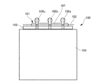
図5は、従来のバリ取り台の基本構成を示す図である。
図5に示すように、このバリ取り台100は、成形品101のパーティングライン(成形金型の分割位置)上に形成されるバリ102を取り去る装置である。バリ取り台100は、基体103と、この基体103上に設けられる載置台105及び3つの押さえ部106a,106b,106cとを備える。これら3つの押さえ部106a,106b,106cは、載置台105の一側から他側にかけて略等間隔に配置される。また、押さえ部106a,106b,106cは、それぞれ、成形品101の製品部107を押さえ付ける押さえ位置と、この押さえ位置から上方に回転した解除位置との間を動作可能である。
図5に示すように、このバリ取り台100は、成形品101のパーティングライン(成形金型の分割位置)上に形成されるバリ102を取り去る装置である。バリ取り台100は、基体103と、この基体103上に設けられる載置台105及び3つの押さえ部106a,106b,106cとを備える。これら3つの押さえ部106a,106b,106cは、載置台105の一側から他側にかけて略等間隔に配置される。また、押さえ部106a,106b,106cは、それぞれ、成形品101の製品部107を押さえ付ける押さえ位置と、この押さえ位置から上方に回転した解除位置との間を動作可能である。
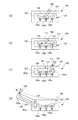
図6は、図5に示される従来のバリ取り台100を用いたバリ取り方法を説明する図である。
図6(a)に示すように、このバリ取り方法では、まず、バリ102の付いた成形品101をロボットアーム装置のアーム部108で把持し、バリ取り台100上の載置台105に載置する。次に、3つの押さえ部106a,106b,106cを押さえ位置に動作させ、成形品101を載置台105に押さえ付ける。
続いて、図6(b)に示すように、アーム部108にナイフ111を装着し、このナイフ111でバリ102の付け根に切り込み112を入れる。この際、移動するナイフ111と押さえ部106a,106b,106cとの干渉を避けるため、押さえ部106a,106b,106cを解除位置に適宜移動させる。
次に、図6(c)に示すように、アーム部108にバリ掴みバンド113を装着し、このバリ掴みバンド113でバリ102の一方の端部102aを把持する。そして、載置台105の一側の押さえ部106aを解除位置に動作させた状態で、アーム部108でバリ102の一方の端部102aを載置台105の他側に引っ張ることにより、押さえ部106bの前までバリ102を剥ぎ取る。同様にして、中央の押さえ部106bを解除位置に動作させた状態で、アーム部108を載置台105の他側にさらに移動させることにより、載置台105の他側の押さえ部106cの前までバリ102を剥ぎ取る。
最後に、図6(d)に示すように、押さえ部106cを解除位置に動作させた状態で、アーム部108を載置台105の他側にさらに移動させることにより、バリ102の他方の端部102bを剥ぎ取る。これで、バリ取りが完了する。
このように、従来のバリ取り方法においては、3つの押さえ部106a,106b,106cのそれぞれが、剥ぎ取られていくバリ102との干渉を防ぐため解除位置に順次動作する。そして、3つの押さえ部106a,106b,106cは、剥ぎ取られたバリ102が通過した後は、再度押さえ位置に動作して成形品101を押さえ付ける。これにより、3つの押さえ部106a,106b,106cのうち1つが解除位置に動作しても、残りの2つで成形品101を載置台105に押さえ付けることができる。このため、バリ102を成形品101から取り去る過程において、常時、成形品101を載置台105に押さえ付けることができる。
ところで、製造コストの低減及び生産性向上の観点から、簡素な工程でバリを機械的に取り去る技術が要望されている。しかし、前述した従来のバリ取り技術において、成形品101からバリ102を完全に取り去るには、アーム部108を載置台105の一側から他側に至る広い範囲で動作させる必要があった。また、常時、成形品101を載置台105に押さえ付けるために、複雑に動作する3つの押さえ部106a,106b,106cが必要であった。
本発明は、このような事情に鑑みてなされたものであり、その目的は、狭い作業範囲でバリを取り去ることができ、しかも成形品を押さえ付ける構成及びその動作の簡素化が図れる成形品のバリ取り方法、成形品のバリ取り台及び成形品のバリ取り装置を提供することにある。
本発明は、以下の構成によって把握される。
(1)本発明の成形品のバリ取り方法は、載置台に成形品を載置する工程(A)と、載置台上の成形品をクランプによって載置台に押さえ付ける工程(B)と、載置台を回転させながら成形品のバリをロボットアーム装置によって剥ぎ取る工程(C)と、を備えることを特徴とする。
(1)本発明の成形品のバリ取り方法は、載置台に成形品を載置する工程(A)と、載置台上の成形品をクランプによって載置台に押さえ付ける工程(B)と、載置台を回転させながら成形品のバリをロボットアーム装置によって剥ぎ取る工程(C)と、を備えることを特徴とする。
(2)本発明の成形品のバリ取り方法は、上記(1)の構成の工程(C)において、成形品をクランプによって載置台に押さえ付けた状態で、載置台の回転がなされることを特徴とする。
(3)本発明の成形品のバリ取り方法は、上記(1)又は(2)の構成の工程(C)が、成形品のバリの最初の部分をロボットアーム装置によって取り去る段階(1)と、載置台を90°以上180°以下の回転角度で回転させ、成形品のバリ取り位置を変える段階(2)と、クランプによって載置台に押さえ付けた成形品のバリの次ぎの部分をロボットアーム装置によって剥ぎ取る段階(3)と、を含むことを特徴とする。
(4)本発明の成形品のバリ取り方法は、上記(1)又は(2)の構成の工程(C)において、載置台をロボットアーム装置の動作に同調させて連続的に360°回転させ、成形品からバリの全部を一度に取り去ることを特徴とする。
(5)本発明の成形品のバリ取り台は、基体と、基体上に回転可能に設けられ、成形品を載置する載置台と、載置台の上方にあって上下方向に移動可能に設けられたクランプと、を備え、クランプが、載置台に載置された成形品からバリを取り去るときに、成形品を載置台に押さえ付け、載置台が、成形品からバリを取り去ることができるように、回転することを特徴とする。
(6)本発明の成形品のバリ取り台は、上記(5)の構成において、クランプが、載置台の回転軸と同軸の回転軸を有し、成形品を載置台に押さえ付けた状態で載置台の回転にともなって回転し得ることを特徴とする。
(7)本発明の成形品のバリ取り台は、上記(5)又は(6)の構成において、載置台が、成形品からバリを部分的に順次取り去ることができるように、90°以上180°以下の回転角度で回転することを特徴とする。
(8)本発明の成形品のバリ取り台は、上記(5)又は(6)の構成において、載置台が、成形品からバリの全部を一度に取り去ることができるように、連続的に360°回転することを特徴とする。
(9)本発明の成形品のバリ取り装置は、上記(5)ないし(8)のいずれか1つのバリ取り台と、バリ取り台に隣接して配置され成形品のバリを取り去るロボットアーム装置と、を備えることを特徴とする。
本発明によれば、狭い作業範囲でバリを取り去ることができ、しかも成形品を押さえ付ける構成及びその動作の簡素化が図れる成形品のバリ取り方法、成形品のバリ取り台及び成形品のバリ取り装置が提供される。
以下、添付図面を参照して、本発明を実施するための形態(以下、「実施形態」と称する)について詳細に説明する。実施形態の説明の全体を通して同じ要素には同じ番号を付している。
(バリ取り装置10の構成)
バリ取り装置10の構成を図1に基づいて説明する。
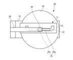
図1に示すように、バリ取り装置10は、ロボットアーム装置20及びバリ取り台30を備える。製造対象である成形品11は、合成樹脂を用いてブロー成形などにより成形されたものであり、製品部(この例では、一方向に長い空調用の中空ダクト)12を有する。この製品部12のパーティングライン上には、バリ13が形成される。バリ13の外形は、平面視において製品部12を囲う略長方形状(図2参照)に形成される。
バリ取り装置10の構成を図1に基づいて説明する。
図1に示すように、バリ取り装置10は、ロボットアーム装置20及びバリ取り台30を備える。製造対象である成形品11は、合成樹脂を用いてブロー成形などにより成形されたものであり、製品部(この例では、一方向に長い空調用の中空ダクト)12を有する。この製品部12のパーティングライン上には、バリ13が形成される。バリ13の外形は、平面視において製品部12を囲う略長方形状(図2参照)に形成される。
なお、本発明にいう「成形品」の構成は、この例に格別に限定されるものではなく、製品部のパーティングライン上にバリが形成される構成であれば、任意である。
(ロボットアーム装置20の構成)
ロボットアーム装置20は、バリ取り台30に隣接して配置される、いわゆる多軸ロボットであって作業用のアーム部21を備える。例えば、ロボットアーム装置20には、アーム部21を上下方向、左右方向及び前後方向に動作させる6軸駆動ロボットを用いることができる。このアーム部21の先端部には、複数種の機能部品が作業の種類に応じて選択的に取付け可能である。例えば、図1では、バリ13を掴むためのバリ掴みバンド22をアーム部21の先端部に装着した例を示すが、このアーム部21の先端部には、この他、載置用治具23(図3(a)参照)やナイフ25(図3(c)参照)などが付け替え可能である。
ロボットアーム装置20は、バリ取り台30に隣接して配置される、いわゆる多軸ロボットであって作業用のアーム部21を備える。例えば、ロボットアーム装置20には、アーム部21を上下方向、左右方向及び前後方向に動作させる6軸駆動ロボットを用いることができる。このアーム部21の先端部には、複数種の機能部品が作業の種類に応じて選択的に取付け可能である。例えば、図1では、バリ13を掴むためのバリ掴みバンド22をアーム部21の先端部に装着した例を示すが、このアーム部21の先端部には、この他、載置用治具23(図3(a)参照)やナイフ25(図3(c)参照)などが付け替え可能である。
(バリ取り台30の構成)
バリ取り台30は、基体31と、この基体31上に設けられる載置台32と、載置台32を回転させる下側駆動部33とを備える。また、バリ取り台30は、載置台32の上方にあって上下方向に移動可能に設けられるクランプ35と、このクランプ35を上下方向に移動させる上側駆動部36とを備える。
バリ取り台30は、基体31と、この基体31上に設けられる載置台32と、載置台32を回転させる下側駆動部33とを備える。また、バリ取り台30は、載置台32の上方にあって上下方向に移動可能に設けられるクランプ35と、このクランプ35を上下方向に移動させる上側駆動部36とを備える。
載置台32は、回転軸37により基体31に対して回転可能に支持される。載置台32の平面形状は、この例では、略円形の平面形状(図2参照)を示すが、成形品11を載置可能であれば、形状は任意である。
下側駆動部33は、基体31の内部に設けられ、任意の回転角度(例えば、90°以上180°以下の回転角度)をもって回転軸37及び載置台32を間欠的に回転させる、あるいは、回転軸37及び載置台32を360°連続的に回転させることができる。下側駆動部33は、電動モータや油圧モータなどの各種の駆動手段から選択可能である。
クランプ35は、成形品11を載置台32に押さえ付ける押さえ部35aと、載置台32の回転軸37と同軸であり押さえ部35aに下端が接続される回転軸35bとを備える。この例では、製品部12の形状に合わせて平面形状が略長方形状に形成される押さえ部35a(図2参照)を示すが、押さえ部35aの平面形状は、成形品11を載置台32に押さえ付けることができる形状であれば、任意である。
回転軸35bは、成形品11を押さえ付けた状態の押さえ部35aを、載置台32の回転にともなって回転させるものである。この例では、基体31の上面に略逆L字状の支持体38を設け、シリンダユニットで構成される上側駆動部36を支持体38に固定する。そして、上側駆動部36のロッドを兼用する回転軸35bの下端に、押さえ部35aの中心部を回転可能に取り付ける。
以上のように構成されるバリ取り台30及びロボットアーム装置20は、制御部41に接続される。この制御部41は、バリ取り台30及びロボットアーム装置20の各部の動作を制御する。より具体的には、制御部41は、下側駆動部33を制御して載置台32の動作を制御し、この載置台32の動作に合わせて上側駆動部36を制御してクランプ35の動作を制御する。また、制御部41は、載置台32の動作及びクランプ35の動作に合わせて、ロボットアーム装置20のアーム部21の動作を制御する。また、6軸駆動ロボット(ロボットアーム装置20)とバリ取り台30を組み合わせる(バリ取り装置10として実質7軸制御となる)ことにより、通常のロボットアームでの作業よりも短時間で細かい制御がされた高精度のバリ処理が可能となる。
(成形品11のバリ取り方法)
次に、バリ取り方法を図3、図4に基づいて説明する。
このバリ取り方法は、バリ取り装置10(図1参照)を用いて成形品11(図1参照)からバリ13(図1参照)を取り去る方法であって、以下に述べる工程(A)、工程(B)及び工程(C)を含む。
次に、バリ取り方法を図3、図4に基づいて説明する。
このバリ取り方法は、バリ取り装置10(図1参照)を用いて成形品11(図1参照)からバリ13(図1参照)を取り去る方法であって、以下に述べる工程(A)、工程(B)及び工程(C)を含む。
(工程(A))
図3(a)に示すように、工程(A)では、アーム部21の先端部に装着した載置用治具23によって、停止した載置台32上に成形品11を載置する(矢印(1))。この際、クランプ35の長手方向に対して成形品11の長手方向を揃えるようにして、クランプ35の直下に製品部12を載置する。
図3(a)に示すように、工程(A)では、アーム部21の先端部に装着した載置用治具23によって、停止した載置台32上に成形品11を載置する(矢印(1))。この際、クランプ35の長手方向に対して成形品11の長手方向を揃えるようにして、クランプ35の直下に製品部12を載置する。
(工程(B))
図3(b)に示すように、工程(B)では、上側駆動部36によりクランプ35を下方に移動させ、載置台32上の成形品11の製品部12をクランプ35の押さえ部35aによって載置台32に押さえ付ける(矢印(2))。
図3(b)に示すように、工程(B)では、上側駆動部36によりクランプ35を下方に移動させ、載置台32上の成形品11の製品部12をクランプ35の押さえ部35aによって載置台32に押さえ付ける(矢印(2))。
次に、図3(c)に示すように、アーム部21の先端部をナイフ25に付け替え、このナイフ25を用いて、載置台32に押さえ付けられた成形品11に切り込み42a,42bを形成する。この際、パーティングラインに沿ってバリ13の付け根に切り込み42aを形成する。これに加え、バリ13を長手方向に2つに分割するための切り込み(この例では、バリ13の短辺と平行でかつバリ13の略中央に位置する切り込み)42bを、製品部12を挟んで2本形成する。
(工程(C))
工程(C)は、例えば、以下の段階(1)~(3)により構成される。
工程(C)は、例えば、以下の段階(1)~(3)により構成される。
(段階(1))
図4(a)に示すように、段階(1)では、アーム部21の先端部をバリ掴みバンド22に付け替え、このバリ掴みバンド22を載置台32の一側に移動させる(矢印(3))。そして、バリ13の長手方向の一方の端部13aをバリ掴みバンド22で掴み、アーム部21を移動させることにより、バリ13の一部分(略半分)15Rを切り込み42a,42bに従って取り去る(矢印(4))。ここで、バリ13の一部分15Rは、本発明にいう「バリの最初の部分」に相当する。
図4(a)に示すように、段階(1)では、アーム部21の先端部をバリ掴みバンド22に付け替え、このバリ掴みバンド22を載置台32の一側に移動させる(矢印(3))。そして、バリ13の長手方向の一方の端部13aをバリ掴みバンド22で掴み、アーム部21を移動させることにより、バリ13の一部分(略半分)15Rを切り込み42a,42bに従って取り去る(矢印(4))。ここで、バリ13の一部分15Rは、本発明にいう「バリの最初の部分」に相当する。
(段階(2))
図4(b)に示すように、段階(2)では、載置台32を任意の回転角度で回転させ、成形品11のバリ取り位置を変える。この例では、載置台32を180°回転させ、載置台32の他側に位置するバリ13の残りの部分15Lを、載置台32の他側から一側に180°反転させる(矢印(5))。この際、クランプ35の押さえ部35aによって成形品11を載置台32に押さえ付けた状態で、つまり製品部12が押さえ部35aと載置台32の間に挟み込まれたまま、載置台32の回転がなされる。
図4(b)に示すように、段階(2)では、載置台32を任意の回転角度で回転させ、成形品11のバリ取り位置を変える。この例では、載置台32を180°回転させ、載置台32の他側に位置するバリ13の残りの部分15Lを、載置台32の他側から一側に180°反転させる(矢印(5))。この際、クランプ35の押さえ部35aによって成形品11を載置台32に押さえ付けた状態で、つまり製品部12が押さえ部35aと載置台32の間に挟み込まれたまま、載置台32の回転がなされる。
(段階(3))
図4(c)に示すように、段階(3)では、バリ掴みバンド22を載置台32の一側に再度移動させる(矢印(6))。そして、バリ13の長手方向の他方の端部13bをバリ掴みバンド22で掴み、アーム部21を移動させる(矢印(7))。これにより、押さえ部35aによって押さえ付けられた成形品11におけるバリ13の残りの部分(本発明にいう「バリの次ぎの部分」に相当)15Lを取り去る。これで、成形品11からのバリ取りが完了し、バリ13が全て取り去られた製品部12が得られる。
図4(c)に示すように、段階(3)では、バリ掴みバンド22を載置台32の一側に再度移動させる(矢印(6))。そして、バリ13の長手方向の他方の端部13bをバリ掴みバンド22で掴み、アーム部21を移動させる(矢印(7))。これにより、押さえ部35aによって押さえ付けられた成形品11におけるバリ13の残りの部分(本発明にいう「バリの次ぎの部分」に相当)15Lを取り去る。これで、成形品11からのバリ取りが完了し、バリ13が全て取り去られた製品部12が得られる。
なお、この例では、段階(2)及び段階(3)をそれぞれ1回行う例を示したが、段階(2)及び段階(3)をそれぞれ2回以上行うことで、バリ13を3つ以上に分割して取り去ることもできる。また、載置台32の回転角度は、180°に限定されるものではなく、成形品の仕様などに応じて、任意の角度に設定可能である。
(実施形態の効果)
以上、説明した実施形態の効果について述べる。
本実施形態によれば、成形品11からバリ13を部分的に順次取り去ることができるように、載置台32を回転させるので、載置台32の一側の狭い範囲でアーム部21を動作させて、成形品11からバリ13を完全に取り去ることができる。すなわち、従来のようにアーム部を載置台の一側から他側まで広く動作させる必要がなく、アーム部21の可動範囲(作業範囲)が、矢印(3),(4)及び矢印(6),(7)(図4参照)で示される狭い範囲で済む。
以上、説明した実施形態の効果について述べる。
本実施形態によれば、成形品11からバリ13を部分的に順次取り去ることができるように、載置台32を回転させるので、載置台32の一側の狭い範囲でアーム部21を動作させて、成形品11からバリ13を完全に取り去ることができる。すなわち、従来のようにアーム部を載置台の一側から他側まで広く動作させる必要がなく、アーム部21の可動範囲(作業範囲)が、矢印(3),(4)及び矢印(6),(7)(図4参照)で示される狭い範囲で済む。
また、バリ13を取り去る過程において、構成が簡素でかつ動作が単純なクランプ35により成形品11を載置台32にしっかりと押さえ付けることができる。
したがって、本実施形態によれば、狭い可動範囲で動作するアーム部21でバリ13を取り去ることができ、しかも成形品11を押さえ付ける構成及びその動作の簡素化が図れるバリ取り技術を提供することができる。
さらに、クランプ35が、成形品11を押さえ付けた状態で載置台32の回転にともなって回転できるので、載置台32が回転している間も、成形品11を載置台32にしっかりと押さえ付けておくことができる。
(成形品11のバリ取り方法の他の例)
前述したバリ取り方法では、工程(C)において、段階(1)~段階(3)により成形品11からバリ13を部分的に順次取り去る方法を例示したが、本発明の成形品のバリ取り方法では、この他、成形品11からバリ13の全部を一度に取り去ることもできる。
前述したバリ取り方法では、工程(C)において、段階(1)~段階(3)により成形品11からバリ13を部分的に順次取り去る方法を例示したが、本発明の成形品のバリ取り方法では、この他、成形品11からバリ13の全部を一度に取り去ることもできる。
例えば、工程(C)において、前述した段階(1)~段階(3)(図4(a)~(c)参照)の代わりに、アーム部21の動作に同調させながら、載置台32を連続的に360°回転させ、成形品11からバリ13の全部を一度に取り去るようにしてよい。この場合、バリ13を長手方向に2つに分割するための切り込み42bは一箇所でもよい。
このようなバリ取り方法においても、狭い可動範囲で動作するアーム部21でバリ13を取り去ることができ、しかも成形品11を押さえ付ける構成及びその動作の簡素化が図れるバリ取り技術を提供することができる。
以上、実施形態を用いて本発明を説明したが、本発明の技術的範囲は上記実施形態に記載の範囲には限定されないことは言うまでもない。上記実施形態に、多様な変更又は改良を加えることが可能であることが当業者に明らかである。またその様な変更又は改良を加えた形態も本発明の技術的範囲に含まれ得ることが、特許請求の範囲の記載から明らかである。
例えば、実施形態においては、載置台32の回転にともなってクランプ35を回転させる例を示したが、載置台32が回転する前に成形品11からクランプ35を上方に移動させ、載置台32の停止した後に再びクランプ35を下方に移動させて成形品11を押さえ付けることもできる。
10 バリ取り装置
11 成形品
13 バリ
15R 一部分(最初の部分)
15L 残りの部分(次の部分)
20 ロボットアーム装置
30 バリ取り台
31 基体
32 載置台
35 クランプ
35b 回転軸
37 回転軸
11 成形品
13 バリ
15R 一部分(最初の部分)
15L 残りの部分(次の部分)
20 ロボットアーム装置
30 バリ取り台
31 基体
32 載置台
35 クランプ
35b 回転軸
37 回転軸
Claims (9)
- 成形品のバリ取り方法であって、
載置台に前記成形品を載置する工程(A)と、
前記載置台上の前記成形品をクランプによって前記載置台に押さえ付ける工程(B)と、
前記載置台を回転させながら前記成形品のバリをロボットアーム装置によって剥ぎ取る工程(C)と、を備えることを特徴とする成形品のバリ取り方法。 - 前記工程(C)において、前記成形品を前記クランプによって前記載置台に押さえ付けた状態で、前記載置台の回転がなされることを特徴とする請求項1に記載の成形品のバリ取り方法。
- 前記工程(C)が、前記成形品のバリの最初の部分を前記ロボットアーム装置によって取り去る段階(1)と、
前記載置台を90°以上180°以下の回転角度で回転させ、前記成形品のバリ取り位置を変える段階(2)と、
前記クランプによって前記載置台に押さえ付けた前記成形品のバリの次ぎの部分を前記ロボットアーム装置によって剥ぎ取る段階(3)と、を含むことを特徴とする請求項1又は2に記載の成形品のバリ取り方法。 - 前記工程(C)において、前記載置台を前記ロボットアーム装置の動作に同調させて連続的に360°回転させ、前記成形品からバリの全部を一度に取り去ることを特徴とする請求項1又は2に記載の成形品のバリ取り方法。
- 成形品のバリ取り台であって、
基体と、
前記基体上に回転可能に設けられ、前記成形品を載置する載置台と、
前記載置台の上方にあって上下方向に移動可能に設けられたクランプと、を備え、
前記クランプが、前記載置台に載置された前記成形品からバリを取り去るときに、前記成形品を前記載置台に押さえ付け、
前記載置台が、前記成形品からバリを取り去ることができるように、回転することを特徴とする成形品のバリ取り台。 - 前記クランプが、前記載置台の回転軸と同軸の回転軸を有し、前記成形品を前記載置台に押さえ付けた状態で前記載置台の回転にともなって回転し得ることを特徴とする請求項5に記載の成形品のバリ取り台。
- 前記載置台が、前記成形品からバリを部分的に順次取り去ることができるように、90°以上180°以下の回転角度で回転することを特徴とする請求項5又は6に記載の成形品のバリ取り台。
- 前記載置台が、前記成形品からバリの全部を一度に取り去ることができるように、連続的に360°回転することを特徴とする請求項5又は6に記載の成形品のバリ取り台。
- 請求項5ないし8のいずれか1項に記載のバリ取り台と、
前記バリ取り台に隣接して配置され前記成形品のバリを取り去るロボットアーム装置と、を備えることを特徴とする成形品のバリ取り装置。
Applications Claiming Priority (2)
| Application Number | Priority Date | Filing Date | Title |
|---|---|---|---|
| JP2014049243A JP6287386B2 (ja) | 2014-03-12 | 2014-03-12 | 成形品のバリ取り方法、成形品のバリ取り台及び成形品のバリ取り装置 |
| JP2014-049243 | 2014-03-12 |
Publications (1)
| Publication Number | Publication Date |
|---|---|
| WO2015136793A1 true WO2015136793A1 (ja) | 2015-09-17 |
Family
ID=54071258
Family Applications (1)
| Application Number | Title | Priority Date | Filing Date |
|---|---|---|---|
| PCT/JP2014/081852 Ceased WO2015136793A1 (ja) | 2014-03-12 | 2014-12-02 | 成形品のバリ取り方法、成形品のバリ取り台及び成形品のバリ取り装置 |
Country Status (2)
| Country | Link |
|---|---|
| JP (1) | JP6287386B2 (ja) |
| WO (1) | WO2015136793A1 (ja) |
Cited By (5)
| Publication number | Priority date | Publication date | Assignee | Title |
|---|---|---|---|---|
| CN106002529A (zh) * | 2016-07-12 | 2016-10-12 | 苏州宏泉高压电容器有限公司 | 一种高压陶瓷电容器瓷介质芯片毛刺去除装置 |
| CN106003393A (zh) * | 2016-07-12 | 2016-10-12 | 苏州宏泉高压电容器有限公司 | 一种高压陶瓷电容器瓷介质芯片毛刺自动清除机 |
| CN108297000A (zh) * | 2018-01-26 | 2018-07-20 | 重庆雷钜电子科技有限公司 | 注塑件夹持装置 |
| US20220063140A1 (en) * | 2019-01-30 | 2022-03-03 | Kyoraku Co., Ltd. | Molding device and system for producing molded article |
| CN115648565A (zh) * | 2022-10-17 | 2023-01-31 | 苏州博大永旺新材股份有限公司 | 一种模具水冷板及应用该模具水冷板的圆盘注塑加工设备 |
Families Citing this family (7)
| Publication number | Priority date | Publication date | Assignee | Title |
|---|---|---|---|---|
| CN105643852B (zh) * | 2016-03-27 | 2017-11-03 | 安徽达来电机有限公司 | 一种电机机筒的修边装置 |
| JP6905176B2 (ja) | 2017-01-17 | 2021-07-21 | オンキヨーホームエンターテイメント株式会社 | 電子機器、及び、電子機器の制御プログラム |
| WO2019049634A1 (ja) | 2017-09-06 | 2019-03-14 | 富士フイルム株式会社 | ガスバリアフィルムおよびガスバリアフィルムの製造方法 |
| KR102021034B1 (ko) * | 2018-04-12 | 2019-09-11 | (주)제이스텍 | 디스플레이 패널용 레이져 커팅 공정 후 보호필름 버 분리장치 |
| KR102052007B1 (ko) * | 2018-04-12 | 2019-12-04 | (주)제이스텍 | 디스플레이 패널용 보호필름 버 제거장치 |
| CN108724276B (zh) * | 2018-05-23 | 2020-04-28 | 浙江利帆家具有限公司 | 一种塑料家具用复合桌面生产装置及其工艺 |
| CN108705598B (zh) * | 2018-05-23 | 2019-10-18 | 浙江利帆家具有限公司 | 抗油污增强高光聚乙烯复合户外桌生产系统及生产方法 |
Citations (5)
| Publication number | Priority date | Publication date | Assignee | Title |
|---|---|---|---|---|
| JPH04185311A (ja) * | 1990-11-16 | 1992-07-02 | Mazda Motor Corp | 樹脂成形品の加工装置 |
| JP2002292642A (ja) * | 2001-04-03 | 2002-10-09 | Kinugawa Rubber Ind Co Ltd | 成形品の加工・搬送装置 |
| JP2003311752A (ja) * | 2002-04-26 | 2003-11-05 | Nippon Plast Co Ltd | 樹脂成形品のバリ除去装置 |
| JP4054486B2 (ja) * | 1999-07-07 | 2008-02-27 | 有限会社 小松原製作所 | ロボットア−ムによる合成樹脂成形品のバリ取り方法及びその装置 |
| JP2011218608A (ja) * | 2010-04-06 | 2011-11-04 | Key Tranding Co Ltd | 箔バリ除去装置 |
-
2014
- 2014-03-12 JP JP2014049243A patent/JP6287386B2/ja active Active
- 2014-12-02 WO PCT/JP2014/081852 patent/WO2015136793A1/ja not_active Ceased
Patent Citations (5)
| Publication number | Priority date | Publication date | Assignee | Title |
|---|---|---|---|---|
| JPH04185311A (ja) * | 1990-11-16 | 1992-07-02 | Mazda Motor Corp | 樹脂成形品の加工装置 |
| JP4054486B2 (ja) * | 1999-07-07 | 2008-02-27 | 有限会社 小松原製作所 | ロボットア−ムによる合成樹脂成形品のバリ取り方法及びその装置 |
| JP2002292642A (ja) * | 2001-04-03 | 2002-10-09 | Kinugawa Rubber Ind Co Ltd | 成形品の加工・搬送装置 |
| JP2003311752A (ja) * | 2002-04-26 | 2003-11-05 | Nippon Plast Co Ltd | 樹脂成形品のバリ除去装置 |
| JP2011218608A (ja) * | 2010-04-06 | 2011-11-04 | Key Tranding Co Ltd | 箔バリ除去装置 |
Cited By (7)
| Publication number | Priority date | Publication date | Assignee | Title |
|---|---|---|---|---|
| CN106002529A (zh) * | 2016-07-12 | 2016-10-12 | 苏州宏泉高压电容器有限公司 | 一种高压陶瓷电容器瓷介质芯片毛刺去除装置 |
| CN106003393A (zh) * | 2016-07-12 | 2016-10-12 | 苏州宏泉高压电容器有限公司 | 一种高压陶瓷电容器瓷介质芯片毛刺自动清除机 |
| CN108297000A (zh) * | 2018-01-26 | 2018-07-20 | 重庆雷钜电子科技有限公司 | 注塑件夹持装置 |
| US20220063140A1 (en) * | 2019-01-30 | 2022-03-03 | Kyoraku Co., Ltd. | Molding device and system for producing molded article |
| US11890802B2 (en) * | 2019-01-30 | 2024-02-06 | Kyoraku Co., Ltd. | Molding device and system for producing molded article |
| CN115648565A (zh) * | 2022-10-17 | 2023-01-31 | 苏州博大永旺新材股份有限公司 | 一种模具水冷板及应用该模具水冷板的圆盘注塑加工设备 |
| CN115648565B (zh) * | 2022-10-17 | 2023-09-22 | 苏州博大永旺新材股份有限公司 | 一种模具水冷板及应用该模具水冷板的圆盘注塑加工设备 |
Also Published As
| Publication number | Publication date |
|---|---|
| JP6287386B2 (ja) | 2018-03-07 |
| JP2015171796A (ja) | 2015-10-01 |
Similar Documents
| Publication | Publication Date | Title |
|---|---|---|
| JP6287386B2 (ja) | 成形品のバリ取り方法、成形品のバリ取り台及び成形品のバリ取り装置 | |
| JP6157195B2 (ja) | プレート状のワークピースに成形部を形成するための方法 | |
| US20170209968A1 (en) | O-ring mounting device and method | |
| JP2015188968A (ja) | 樹脂シートの分断方法及び分断装置 | |
| TWM523536U (zh) | 物件毛邊加工機 | |
| JP2016209889A (ja) | 省スペース型の配管分岐部一体成形装置及び成形方法 | |
| CN204546252U (zh) | 研磨夹头 | |
| CN204700600U (zh) | 旋转定位装置 | |
| CN206644292U (zh) | 一种细浇口余料切除设备 | |
| CN204870280U (zh) | 雕刻机换刀机构 | |
| JP2001018238A (ja) | ロボットア−ムによる合成樹脂成形品のバリ取り方法及びその装置 | |
| JP3194870U (ja) | 五軸加工機に設置する超音波定位装置 | |
| CN103692838B (zh) | 锅具外表面的滚花加工设备及其加工工艺 | |
| CN104175779B (zh) | 雕刻机和雕刻机的装夹台 | |
| CN208690856U (zh) | 剥线工具 | |
| CN205290069U (zh) | 镭射机用旋转移动工作台及使用其的镭射机 | |
| CN111185780B (zh) | 换产调整方法和加工系统 | |
| CN202872163U (zh) | 气剥机 | |
| CN207723498U (zh) | 一种自动换装零件装置 | |
| CN223834899U (zh) | 一种塑料成型后的毛边切除设备 | |
| CN205343693U (zh) | 注塑机用全自动模内剪料机械臂 | |
| CN105195803A (zh) | 一种切断夹具 | |
| CN204748749U (zh) | 用于辅助切割的夹持装置 | |
| CN105081837B (zh) | 夹具结构 | |
| CN203920191U (zh) | 设有旋转台的雕刻机 |
Legal Events
| Date | Code | Title | Description |
|---|---|---|---|
| 121 | Ep: the epo has been informed by wipo that ep was designated in this application |
Ref document number: 14885225 Country of ref document: EP Kind code of ref document: A1 |
|
| NENP | Non-entry into the national phase |
Ref country code: DE |
|
| 122 | Ep: pct application non-entry in european phase |
Ref document number: 14885225 Country of ref document: EP Kind code of ref document: A1 |