WO2015129691A1 - 4輪駆動車のクラッチ制御装置 - Google Patents
4輪駆動車のクラッチ制御装置 Download PDFInfo
- Publication number
- WO2015129691A1 WO2015129691A1 PCT/JP2015/055246 JP2015055246W WO2015129691A1 WO 2015129691 A1 WO2015129691 A1 WO 2015129691A1 JP 2015055246 W JP2015055246 W JP 2015055246W WO 2015129691 A1 WO2015129691 A1 WO 2015129691A1
- Authority
- WO
- WIPO (PCT)
- Prior art keywords
- wheel drive
- clutch
- vehicle
- wheel
- control device
- Prior art date
Links
- 230000005540 biological transmission Effects 0.000 claims abstract description 37
- 238000007562 laser obscuration time method Methods 0.000 claims abstract description 3
- 230000001360 synchronised effect Effects 0.000 claims description 36
- 230000007704 transition Effects 0.000 claims description 28
- 230000007246 mechanism Effects 0.000 claims description 13
- 238000012546 transfer Methods 0.000 claims description 13
- 238000001514 detection method Methods 0.000 claims description 10
- 230000007423 decrease Effects 0.000 claims description 9
- 238000011144 upstream manufacturing Methods 0.000 claims description 6
- 230000008878 coupling Effects 0.000 abstract description 64
- 238000010168 coupling process Methods 0.000 abstract description 64
- 238000005859 coupling reaction Methods 0.000 abstract description 64
- 238000000034 method Methods 0.000 description 20
- 230000008569 process Effects 0.000 description 20
- 230000001133 acceleration Effects 0.000 description 13
- 230000035939 shock Effects 0.000 description 13
- 230000000694 effects Effects 0.000 description 8
- 230000008859 change Effects 0.000 description 7
- 230000000052 comparative effect Effects 0.000 description 7
- 238000010586 diagram Methods 0.000 description 6
- 238000004891 communication Methods 0.000 description 5
- 230000003247 decreasing effect Effects 0.000 description 5
- 239000000446 fuel Substances 0.000 description 5
- 230000009471 action Effects 0.000 description 4
- 238000013019 agitation Methods 0.000 description 4
- 238000012545 processing Methods 0.000 description 4
- 230000004044 response Effects 0.000 description 4
- 230000004043 responsiveness Effects 0.000 description 4
- AGGKEGLBGGJEBZ-UHFFFAOYSA-N tetramethylenedisulfotetramine Chemical compound C1N(S2(=O)=O)CN3S(=O)(=O)N1CN2C3 AGGKEGLBGGJEBZ-UHFFFAOYSA-N 0.000 description 4
- 230000002411 adverse Effects 0.000 description 3
- 230000009194 climbing Effects 0.000 description 2
- 230000003111 delayed effect Effects 0.000 description 2
- 230000000881 depressing effect Effects 0.000 description 2
- 230000000994 depressogenic effect Effects 0.000 description 2
- 238000007792 addition Methods 0.000 description 1
- 238000013461 design Methods 0.000 description 1
- 239000012530 fluid Substances 0.000 description 1
- 230000002441 reversible effect Effects 0.000 description 1
- 230000000630 rising effect Effects 0.000 description 1
Images


Classifications
-
- B—PERFORMING OPERATIONS; TRANSPORTING
- B60—VEHICLES IN GENERAL
- B60K—ARRANGEMENT OR MOUNTING OF PROPULSION UNITS OR OF TRANSMISSIONS IN VEHICLES; ARRANGEMENT OR MOUNTING OF PLURAL DIVERSE PRIME-MOVERS IN VEHICLES; AUXILIARY DRIVES FOR VEHICLES; INSTRUMENTATION OR DASHBOARDS FOR VEHICLES; ARRANGEMENTS IN CONNECTION WITH COOLING, AIR INTAKE, GAS EXHAUST OR FUEL SUPPLY OF PROPULSION UNITS IN VEHICLES
- B60K23/00—Arrangement or mounting of control devices for vehicle transmissions, or parts thereof, not otherwise provided for
- B60K23/08—Arrangement or mounting of control devices for vehicle transmissions, or parts thereof, not otherwise provided for for changing number of driven wheels, for switching from driving one axle to driving two or more axles
- B60K23/0808—Arrangement or mounting of control devices for vehicle transmissions, or parts thereof, not otherwise provided for for changing number of driven wheels, for switching from driving one axle to driving two or more axles for varying torque distribution between driven axles, e.g. by transfer clutch
-
- B—PERFORMING OPERATIONS; TRANSPORTING
- B60—VEHICLES IN GENERAL
- B60K—ARRANGEMENT OR MOUNTING OF PROPULSION UNITS OR OF TRANSMISSIONS IN VEHICLES; ARRANGEMENT OR MOUNTING OF PLURAL DIVERSE PRIME-MOVERS IN VEHICLES; AUXILIARY DRIVES FOR VEHICLES; INSTRUMENTATION OR DASHBOARDS FOR VEHICLES; ARRANGEMENTS IN CONNECTION WITH COOLING, AIR INTAKE, GAS EXHAUST OR FUEL SUPPLY OF PROPULSION UNITS IN VEHICLES
- B60K23/00—Arrangement or mounting of control devices for vehicle transmissions, or parts thereof, not otherwise provided for
- B60K23/08—Arrangement or mounting of control devices for vehicle transmissions, or parts thereof, not otherwise provided for for changing number of driven wheels, for switching from driving one axle to driving two or more axles
-
- B—PERFORMING OPERATIONS; TRANSPORTING
- B60—VEHICLES IN GENERAL
- B60K—ARRANGEMENT OR MOUNTING OF PROPULSION UNITS OR OF TRANSMISSIONS IN VEHICLES; ARRANGEMENT OR MOUNTING OF PLURAL DIVERSE PRIME-MOVERS IN VEHICLES; AUXILIARY DRIVES FOR VEHICLES; INSTRUMENTATION OR DASHBOARDS FOR VEHICLES; ARRANGEMENTS IN CONNECTION WITH COOLING, AIR INTAKE, GAS EXHAUST OR FUEL SUPPLY OF PROPULSION UNITS IN VEHICLES
- B60K17/00—Arrangement or mounting of transmissions in vehicles
- B60K17/02—Arrangement or mounting of transmissions in vehicles characterised by arrangement, location, or kind of clutch
-
- B—PERFORMING OPERATIONS; TRANSPORTING
- B60—VEHICLES IN GENERAL
- B60K—ARRANGEMENT OR MOUNTING OF PROPULSION UNITS OR OF TRANSMISSIONS IN VEHICLES; ARRANGEMENT OR MOUNTING OF PLURAL DIVERSE PRIME-MOVERS IN VEHICLES; AUXILIARY DRIVES FOR VEHICLES; INSTRUMENTATION OR DASHBOARDS FOR VEHICLES; ARRANGEMENTS IN CONNECTION WITH COOLING, AIR INTAKE, GAS EXHAUST OR FUEL SUPPLY OF PROPULSION UNITS IN VEHICLES
- B60K17/00—Arrangement or mounting of transmissions in vehicles
- B60K17/34—Arrangement or mounting of transmissions in vehicles for driving both front and rear wheels, e.g. four wheel drive vehicles
- B60K17/344—Arrangement or mounting of transmissions in vehicles for driving both front and rear wheels, e.g. four wheel drive vehicles having a transfer gear
-
- B—PERFORMING OPERATIONS; TRANSPORTING
- B60—VEHICLES IN GENERAL
- B60K—ARRANGEMENT OR MOUNTING OF PROPULSION UNITS OR OF TRANSMISSIONS IN VEHICLES; ARRANGEMENT OR MOUNTING OF PLURAL DIVERSE PRIME-MOVERS IN VEHICLES; AUXILIARY DRIVES FOR VEHICLES; INSTRUMENTATION OR DASHBOARDS FOR VEHICLES; ARRANGEMENTS IN CONNECTION WITH COOLING, AIR INTAKE, GAS EXHAUST OR FUEL SUPPLY OF PROPULSION UNITS IN VEHICLES
- B60K17/00—Arrangement or mounting of transmissions in vehicles
- B60K17/34—Arrangement or mounting of transmissions in vehicles for driving both front and rear wheels, e.g. four wheel drive vehicles
- B60K17/348—Arrangement or mounting of transmissions in vehicles for driving both front and rear wheels, e.g. four wheel drive vehicles having differential means for driving one set of wheels, e.g. the front, at one speed and the other set, e.g. the rear, at a different speed
- B60K17/35—Arrangement or mounting of transmissions in vehicles for driving both front and rear wheels, e.g. four wheel drive vehicles having differential means for driving one set of wheels, e.g. the front, at one speed and the other set, e.g. the rear, at a different speed including arrangements for suppressing or influencing the power transfer, e.g. viscous clutches
-
- B—PERFORMING OPERATIONS; TRANSPORTING
- B60—VEHICLES IN GENERAL
- B60W—CONJOINT CONTROL OF VEHICLE SUB-UNITS OF DIFFERENT TYPE OR DIFFERENT FUNCTION; CONTROL SYSTEMS SPECIALLY ADAPTED FOR HYBRID VEHICLES; ROAD VEHICLE DRIVE CONTROL SYSTEMS FOR PURPOSES NOT RELATED TO THE CONTROL OF A PARTICULAR SUB-UNIT
- B60W10/00—Conjoint control of vehicle sub-units of different type or different function
- B60W10/02—Conjoint control of vehicle sub-units of different type or different function including control of driveline clutches
-
- B—PERFORMING OPERATIONS; TRANSPORTING
- B60—VEHICLES IN GENERAL
- B60W—CONJOINT CONTROL OF VEHICLE SUB-UNITS OF DIFFERENT TYPE OR DIFFERENT FUNCTION; CONTROL SYSTEMS SPECIALLY ADAPTED FOR HYBRID VEHICLES; ROAD VEHICLE DRIVE CONTROL SYSTEMS FOR PURPOSES NOT RELATED TO THE CONTROL OF A PARTICULAR SUB-UNIT
- B60W10/00—Conjoint control of vehicle sub-units of different type or different function
- B60W10/04—Conjoint control of vehicle sub-units of different type or different function including control of propulsion units
-
- B—PERFORMING OPERATIONS; TRANSPORTING
- B60—VEHICLES IN GENERAL
- B60W—CONJOINT CONTROL OF VEHICLE SUB-UNITS OF DIFFERENT TYPE OR DIFFERENT FUNCTION; CONTROL SYSTEMS SPECIALLY ADAPTED FOR HYBRID VEHICLES; ROAD VEHICLE DRIVE CONTROL SYSTEMS FOR PURPOSES NOT RELATED TO THE CONTROL OF A PARTICULAR SUB-UNIT
- B60W10/00—Conjoint control of vehicle sub-units of different type or different function
- B60W10/119—Conjoint control of vehicle sub-units of different type or different function including control of all-wheel-driveline means, e.g. transfer gears or clutches for dividing torque between front and rear axle
-
- B—PERFORMING OPERATIONS; TRANSPORTING
- B60—VEHICLES IN GENERAL
- B60W—CONJOINT CONTROL OF VEHICLE SUB-UNITS OF DIFFERENT TYPE OR DIFFERENT FUNCTION; CONTROL SYSTEMS SPECIALLY ADAPTED FOR HYBRID VEHICLES; ROAD VEHICLE DRIVE CONTROL SYSTEMS FOR PURPOSES NOT RELATED TO THE CONTROL OF A PARTICULAR SUB-UNIT
- B60W10/00—Conjoint control of vehicle sub-units of different type or different function
- B60W10/12—Conjoint control of vehicle sub-units of different type or different function including control of differentials
- B60W10/16—Axle differentials, e.g. for dividing torque between left and right wheels
-
- B—PERFORMING OPERATIONS; TRANSPORTING
- B60—VEHICLES IN GENERAL
- B60W—CONJOINT CONTROL OF VEHICLE SUB-UNITS OF DIFFERENT TYPE OR DIFFERENT FUNCTION; CONTROL SYSTEMS SPECIALLY ADAPTED FOR HYBRID VEHICLES; ROAD VEHICLE DRIVE CONTROL SYSTEMS FOR PURPOSES NOT RELATED TO THE CONTROL OF A PARTICULAR SUB-UNIT
- B60W30/00—Purposes of road vehicle drive control systems not related to the control of a particular sub-unit, e.g. of systems using conjoint control of vehicle sub-units
- B60W30/02—Control of vehicle driving stability
- B60W30/045—Improving turning performance
-
- B—PERFORMING OPERATIONS; TRANSPORTING
- B60—VEHICLES IN GENERAL
- B60W—CONJOINT CONTROL OF VEHICLE SUB-UNITS OF DIFFERENT TYPE OR DIFFERENT FUNCTION; CONTROL SYSTEMS SPECIALLY ADAPTED FOR HYBRID VEHICLES; ROAD VEHICLE DRIVE CONTROL SYSTEMS FOR PURPOSES NOT RELATED TO THE CONTROL OF A PARTICULAR SUB-UNIT
- B60W40/00—Estimation or calculation of non-directly measurable driving parameters for road vehicle drive control systems not related to the control of a particular sub unit, e.g. by using mathematical models
- B60W40/10—Estimation or calculation of non-directly measurable driving parameters for road vehicle drive control systems not related to the control of a particular sub unit, e.g. by using mathematical models related to vehicle motion
- B60W40/101—Side slip angle of tyre
-
- B—PERFORMING OPERATIONS; TRANSPORTING
- B60—VEHICLES IN GENERAL
- B60W—CONJOINT CONTROL OF VEHICLE SUB-UNITS OF DIFFERENT TYPE OR DIFFERENT FUNCTION; CONTROL SYSTEMS SPECIALLY ADAPTED FOR HYBRID VEHICLES; ROAD VEHICLE DRIVE CONTROL SYSTEMS FOR PURPOSES NOT RELATED TO THE CONTROL OF A PARTICULAR SUB-UNIT
- B60W40/00—Estimation or calculation of non-directly measurable driving parameters for road vehicle drive control systems not related to the control of a particular sub unit, e.g. by using mathematical models
- B60W40/10—Estimation or calculation of non-directly measurable driving parameters for road vehicle drive control systems not related to the control of a particular sub unit, e.g. by using mathematical models related to vehicle motion
- B60W40/114—Yaw movement
-
- F—MECHANICAL ENGINEERING; LIGHTING; HEATING; WEAPONS; BLASTING
- F16—ENGINEERING ELEMENTS AND UNITS; GENERAL MEASURES FOR PRODUCING AND MAINTAINING EFFECTIVE FUNCTIONING OF MACHINES OR INSTALLATIONS; THERMAL INSULATION IN GENERAL
- F16D—COUPLINGS FOR TRANSMITTING ROTATION; CLUTCHES; BRAKES
- F16D11/00—Clutches in which the members have interengaging parts
-
- F—MECHANICAL ENGINEERING; LIGHTING; HEATING; WEAPONS; BLASTING
- F16—ENGINEERING ELEMENTS AND UNITS; GENERAL MEASURES FOR PRODUCING AND MAINTAINING EFFECTIVE FUNCTIONING OF MACHINES OR INSTALLATIONS; THERMAL INSULATION IN GENERAL
- F16D—COUPLINGS FOR TRANSMITTING ROTATION; CLUTCHES; BRAKES
- F16D13/00—Friction clutches
-
- F—MECHANICAL ENGINEERING; LIGHTING; HEATING; WEAPONS; BLASTING
- F16—ENGINEERING ELEMENTS AND UNITS; GENERAL MEASURES FOR PRODUCING AND MAINTAINING EFFECTIVE FUNCTIONING OF MACHINES OR INSTALLATIONS; THERMAL INSULATION IN GENERAL
- F16D—COUPLINGS FOR TRANSMITTING ROTATION; CLUTCHES; BRAKES
- F16D21/00—Systems comprising a plurality of actuated clutches
-
- F—MECHANICAL ENGINEERING; LIGHTING; HEATING; WEAPONS; BLASTING
- F16—ENGINEERING ELEMENTS AND UNITS; GENERAL MEASURES FOR PRODUCING AND MAINTAINING EFFECTIVE FUNCTIONING OF MACHINES OR INSTALLATIONS; THERMAL INSULATION IN GENERAL
- F16D—COUPLINGS FOR TRANSMITTING ROTATION; CLUTCHES; BRAKES
- F16D23/00—Details of mechanically-actuated clutches not specific for one distinct type
- F16D23/02—Arrangements for synchronisation, also for power-operated clutches
-
- F—MECHANICAL ENGINEERING; LIGHTING; HEATING; WEAPONS; BLASTING
- F16—ENGINEERING ELEMENTS AND UNITS; GENERAL MEASURES FOR PRODUCING AND MAINTAINING EFFECTIVE FUNCTIONING OF MACHINES OR INSTALLATIONS; THERMAL INSULATION IN GENERAL
- F16D—COUPLINGS FOR TRANSMITTING ROTATION; CLUTCHES; BRAKES
- F16D48/00—External control of clutches
- F16D48/06—Control by electric or electronic means, e.g. of fluid pressure
-
- B—PERFORMING OPERATIONS; TRANSPORTING
- B60—VEHICLES IN GENERAL
- B60K—ARRANGEMENT OR MOUNTING OF PROPULSION UNITS OR OF TRANSMISSIONS IN VEHICLES; ARRANGEMENT OR MOUNTING OF PLURAL DIVERSE PRIME-MOVERS IN VEHICLES; AUXILIARY DRIVES FOR VEHICLES; INSTRUMENTATION OR DASHBOARDS FOR VEHICLES; ARRANGEMENTS IN CONNECTION WITH COOLING, AIR INTAKE, GAS EXHAUST OR FUEL SUPPLY OF PROPULSION UNITS IN VEHICLES
- B60K17/00—Arrangement or mounting of transmissions in vehicles
- B60K17/34—Arrangement or mounting of transmissions in vehicles for driving both front and rear wheels, e.g. four wheel drive vehicles
- B60K17/348—Arrangement or mounting of transmissions in vehicles for driving both front and rear wheels, e.g. four wheel drive vehicles having differential means for driving one set of wheels, e.g. the front, at one speed and the other set, e.g. the rear, at a different speed
- B60K17/35—Arrangement or mounting of transmissions in vehicles for driving both front and rear wheels, e.g. four wheel drive vehicles having differential means for driving one set of wheels, e.g. the front, at one speed and the other set, e.g. the rear, at a different speed including arrangements for suppressing or influencing the power transfer, e.g. viscous clutches
- B60K17/3515—Arrangement or mounting of transmissions in vehicles for driving both front and rear wheels, e.g. four wheel drive vehicles having differential means for driving one set of wheels, e.g. the front, at one speed and the other set, e.g. the rear, at a different speed including arrangements for suppressing or influencing the power transfer, e.g. viscous clutches with a clutch adjacent to traction wheel, e.g. automatic wheel hub
-
- B—PERFORMING OPERATIONS; TRANSPORTING
- B60—VEHICLES IN GENERAL
- B60W—CONJOINT CONTROL OF VEHICLE SUB-UNITS OF DIFFERENT TYPE OR DIFFERENT FUNCTION; CONTROL SYSTEMS SPECIALLY ADAPTED FOR HYBRID VEHICLES; ROAD VEHICLE DRIVE CONTROL SYSTEMS FOR PURPOSES NOT RELATED TO THE CONTROL OF A PARTICULAR SUB-UNIT
- B60W2510/00—Input parameters relating to a particular sub-units
- B60W2510/06—Combustion engines, Gas turbines
- B60W2510/0604—Throttle position
-
- B—PERFORMING OPERATIONS; TRANSPORTING
- B60—VEHICLES IN GENERAL
- B60W—CONJOINT CONTROL OF VEHICLE SUB-UNITS OF DIFFERENT TYPE OR DIFFERENT FUNCTION; CONTROL SYSTEMS SPECIALLY ADAPTED FOR HYBRID VEHICLES; ROAD VEHICLE DRIVE CONTROL SYSTEMS FOR PURPOSES NOT RELATED TO THE CONTROL OF A PARTICULAR SUB-UNIT
- B60W2510/00—Input parameters relating to a particular sub-units
- B60W2510/06—Combustion engines, Gas turbines
- B60W2510/0638—Engine speed
-
- B—PERFORMING OPERATIONS; TRANSPORTING
- B60—VEHICLES IN GENERAL
- B60W—CONJOINT CONTROL OF VEHICLE SUB-UNITS OF DIFFERENT TYPE OR DIFFERENT FUNCTION; CONTROL SYSTEMS SPECIALLY ADAPTED FOR HYBRID VEHICLES; ROAD VEHICLE DRIVE CONTROL SYSTEMS FOR PURPOSES NOT RELATED TO THE CONTROL OF A PARTICULAR SUB-UNIT
- B60W2510/00—Input parameters relating to a particular sub-units
- B60W2510/10—Change speed gearings
- B60W2510/1015—Input shaft speed, e.g. turbine speed
-
- B—PERFORMING OPERATIONS; TRANSPORTING
- B60—VEHICLES IN GENERAL
- B60W—CONJOINT CONTROL OF VEHICLE SUB-UNITS OF DIFFERENT TYPE OR DIFFERENT FUNCTION; CONTROL SYSTEMS SPECIALLY ADAPTED FOR HYBRID VEHICLES; ROAD VEHICLE DRIVE CONTROL SYSTEMS FOR PURPOSES NOT RELATED TO THE CONTROL OF A PARTICULAR SUB-UNIT
- B60W2510/00—Input parameters relating to a particular sub-units
- B60W2510/10—Change speed gearings
- B60W2510/104—Output speed
-
- B—PERFORMING OPERATIONS; TRANSPORTING
- B60—VEHICLES IN GENERAL
- B60W—CONJOINT CONTROL OF VEHICLE SUB-UNITS OF DIFFERENT TYPE OR DIFFERENT FUNCTION; CONTROL SYSTEMS SPECIALLY ADAPTED FOR HYBRID VEHICLES; ROAD VEHICLE DRIVE CONTROL SYSTEMS FOR PURPOSES NOT RELATED TO THE CONTROL OF A PARTICULAR SUB-UNIT
- B60W2520/00—Input parameters relating to overall vehicle dynamics
- B60W2520/10—Longitudinal speed
- B60W2520/105—Longitudinal acceleration
-
- B—PERFORMING OPERATIONS; TRANSPORTING
- B60—VEHICLES IN GENERAL
- B60W—CONJOINT CONTROL OF VEHICLE SUB-UNITS OF DIFFERENT TYPE OR DIFFERENT FUNCTION; CONTROL SYSTEMS SPECIALLY ADAPTED FOR HYBRID VEHICLES; ROAD VEHICLE DRIVE CONTROL SYSTEMS FOR PURPOSES NOT RELATED TO THE CONTROL OF A PARTICULAR SUB-UNIT
- B60W2520/00—Input parameters relating to overall vehicle dynamics
- B60W2520/28—Wheel speed
-
- B—PERFORMING OPERATIONS; TRANSPORTING
- B60—VEHICLES IN GENERAL
- B60W—CONJOINT CONTROL OF VEHICLE SUB-UNITS OF DIFFERENT TYPE OR DIFFERENT FUNCTION; CONTROL SYSTEMS SPECIALLY ADAPTED FOR HYBRID VEHICLES; ROAD VEHICLE DRIVE CONTROL SYSTEMS FOR PURPOSES NOT RELATED TO THE CONTROL OF A PARTICULAR SUB-UNIT
- B60W2540/00—Input parameters relating to occupants
- B60W2540/10—Accelerator pedal position
-
- B—PERFORMING OPERATIONS; TRANSPORTING
- B60—VEHICLES IN GENERAL
- B60W—CONJOINT CONTROL OF VEHICLE SUB-UNITS OF DIFFERENT TYPE OR DIFFERENT FUNCTION; CONTROL SYSTEMS SPECIALLY ADAPTED FOR HYBRID VEHICLES; ROAD VEHICLE DRIVE CONTROL SYSTEMS FOR PURPOSES NOT RELATED TO THE CONTROL OF A PARTICULAR SUB-UNIT
- B60W2540/00—Input parameters relating to occupants
- B60W2540/18—Steering angle
-
- B—PERFORMING OPERATIONS; TRANSPORTING
- B60—VEHICLES IN GENERAL
- B60Y—INDEXING SCHEME RELATING TO ASPECTS CROSS-CUTTING VEHICLE TECHNOLOGY
- B60Y2400/00—Special features of vehicle units
- B60Y2400/42—Clutches or brakes
- B60Y2400/421—Dog type clutches or brakes
-
- B—PERFORMING OPERATIONS; TRANSPORTING
- B60—VEHICLES IN GENERAL
- B60Y—INDEXING SCHEME RELATING TO ASPECTS CROSS-CUTTING VEHICLE TECHNOLOGY
- B60Y2400/00—Special features of vehicle units
- B60Y2400/42—Clutches or brakes
- B60Y2400/424—Friction clutches
-
- F—MECHANICAL ENGINEERING; LIGHTING; HEATING; WEAPONS; BLASTING
- F16—ENGINEERING ELEMENTS AND UNITS; GENERAL MEASURES FOR PRODUCING AND MAINTAINING EFFECTIVE FUNCTIONING OF MACHINES OR INSTALLATIONS; THERMAL INSULATION IN GENERAL
- F16D—COUPLINGS FOR TRANSMITTING ROTATION; CLUTCHES; BRAKES
- F16D2500/00—External control of clutches by electric or electronic means
- F16D2500/10—System to be controlled
- F16D2500/104—Clutch
- F16D2500/10406—Clutch position
- F16D2500/10431—4WD Clutch dividing power between the front and the rear axle
-
- F—MECHANICAL ENGINEERING; LIGHTING; HEATING; WEAPONS; BLASTING
- F16—ENGINEERING ELEMENTS AND UNITS; GENERAL MEASURES FOR PRODUCING AND MAINTAINING EFFECTIVE FUNCTIONING OF MACHINES OR INSTALLATIONS; THERMAL INSULATION IN GENERAL
- F16D—COUPLINGS FOR TRANSMITTING ROTATION; CLUTCHES; BRAKES
- F16D2500/00—External control of clutches by electric or electronic means
- F16D2500/30—Signal inputs
- F16D2500/31—Signal inputs from the vehicle
- F16D2500/3108—Vehicle speed
-
- F—MECHANICAL ENGINEERING; LIGHTING; HEATING; WEAPONS; BLASTING
- F16—ENGINEERING ELEMENTS AND UNITS; GENERAL MEASURES FOR PRODUCING AND MAINTAINING EFFECTIVE FUNCTIONING OF MACHINES OR INSTALLATIONS; THERMAL INSULATION IN GENERAL
- F16D—COUPLINGS FOR TRANSMITTING ROTATION; CLUTCHES; BRAKES
- F16D2500/00—External control of clutches by electric or electronic means
- F16D2500/70—Details about the implementation of the control system
- F16D2500/704—Output parameters from the control unit; Target parameters to be controlled
- F16D2500/70422—Clutch parameters
- F16D2500/70424—Outputting a clutch engaged-disengaged signal
-
- F—MECHANICAL ENGINEERING; LIGHTING; HEATING; WEAPONS; BLASTING
- F16—ENGINEERING ELEMENTS AND UNITS; GENERAL MEASURES FOR PRODUCING AND MAINTAINING EFFECTIVE FUNCTIONING OF MACHINES OR INSTALLATIONS; THERMAL INSULATION IN GENERAL
- F16D—COUPLINGS FOR TRANSMITTING ROTATION; CLUTCHES; BRAKES
- F16D2500/00—External control of clutches by electric or electronic means
- F16D2500/70—Details about the implementation of the control system
- F16D2500/706—Strategy of control
- F16D2500/7061—Feed-back
Definitions
- the present invention relates to a clutch control device for a four-wheel drive vehicle having a meshing clutch and a friction clutch in a driving force transmission system to auxiliary driving wheels.
- a front-wheel drive-based four-wheel drive vehicle having a meshing clutch and a friction clutch in a driving force transmission system to the rear wheels is known (for example, see Patent Document 1).
- the friction clutch when switching from the two-wheel drive mode to the four-wheel drive mode, the friction clutch is fastened, the drive source side of the meshing clutch is synchronized with the rear wheel side, and then the meshing clutch is fastened. Further, when switching from the four-wheel drive mode to the two-wheel drive mode, the mesh clutch is released after the friction clutch is released.
- the present invention has been made by paying attention to the above-described problem, and is a four-wheel drive capable of improving the behavior stability of the vehicle and improving the sound and vibration characteristics of the vehicle by optimizing the synchronization speed of the meshing clutch.
- An object of the present invention is to provide a vehicle clutch control device.
- the present invention provides: As a clutch interposed between the drive source and the sub drive wheel, among the drive force transmission system to the sub drive wheel, the drive branch side transmission system path and the sub drive wheel side transmission system path across the differential Each has a meshing clutch and a friction clutch arranged separately, When the vehicle is decelerating during the transition from the disconnect two-wheel drive mode in which both clutches are engaged to the four-wheel drive mode in which both clutches are engaged in the clutch control unit that controls the engagement and release of the mesh clutch and the friction clutch.
- the clutch control device for a four-wheel drive vehicle is provided with a synchronous speed control unit that reduces the synchronous speed of the meshing clutch as compared with the non-decelerating state.
- the clutch control unit lowers the synchronization speed of the meshing clutch when the meshing clutch is engaged at the time of deceleration compared to the non-decelerating mode.
- the shock generated by the engagement of the meshing clutch during deceleration can be reduced as compared with that during non-deceleration, and the sound and vibration characteristics of the vehicle can be improved.
- the clutch control unit controls the synchronization speed of the meshing clutch to be higher than that during deceleration when the meshing clutch is engaged when not decelerating.
- the engagement timing of the meshing clutch at the time of non-deceleration such as acceleration becomes earlier than that at the time of deceleration, so that the control response can be improved and the stability of the vehicle behavior can be improved.
- FIG. 6 is a map diagram showing a drive mode switching map according to a vehicle speed and an accelerator opening used in clutch control when “auto mode” in the first embodiment is selected.
- FIG. 3 is a drive mode transition diagram showing switching transition of drive modes (disconnect two-wheel drive mode, standby two-wheel drive mode, and connect four-wheel drive mode) by clutch control by the clutch control device of the first embodiment.
- FIG. 4 is a flowchart showing a flow of a clutch control process in an “auto mode” executed in the 4WD control unit of the clutch control device for a four-wheel drive vehicle according to the first embodiment.
- 3 is a flowchart showing a flow of a synchronous speed control process executed in a synchronous speed control unit of the clutch control device for a four-wheel drive vehicle according to the first embodiment.
- It is a time chart which shows operation
- 6 is a time chart showing an operation when the synchronous speed of the dog clutch is reduced during vehicle deceleration by the clutch control device for a four-wheel drive vehicle of the first embodiment.
- FIG. 10 is a map diagram showing another example of a drive mode switching map according to a vehicle speed and an accelerator opening used in clutch control when “auto mode” is selected.
- FIG. 5 is a drive system configuration diagram showing a drive system configuration of a rear wheel drive base four-wheel drive vehicle to which the clutch control device of the second embodiment is applied.
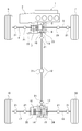
- FIG. 1 shows a drive system configuration of a front-wheel drive-based four-wheel drive vehicle to which the clutch control device of the first embodiment is applied.
- the drive system configuration of the four-wheel drive vehicle will be described with reference to FIG.
- the front wheel drive system of the four-wheel drive vehicle includes a horizontally mounted engine 1 (drive source), a transmission 2, a front differential 3, a left front wheel drive shaft 4, and a right front wheel drive shaft 5. And a left front wheel 6 (main drive wheel) and a right front wheel 7 (main drive wheel). That is, the driving force that has passed through the horizontally mounted engine 1 and the transmission 2 is transmitted to the left and right front wheel drive shafts 4 and 5 via the front differential 3, and always drives the left and right front wheels 6 and 7 while allowing the differential.
- a horizontally mounted engine 1 drive source
- a transmission 2 a transmission 2
- a front differential 3 a left front wheel drive shaft 4
- a right front wheel 7 main drive wheel
- the rear wheel drive system of the four-wheel drive vehicle includes a dog clutch 8 (meshing clutch), a bevel gear 9, an output pinion 10, a rear wheel output shaft 11, and a propeller shaft 12. ing.
- 21 is a universal joint.
- the rotation between the bevel gear 9 and the ring gear 14 of the rear wheel drive system is stopped, so that the friction loss, the oil agitation loss, etc. are suppressed, and the fuel efficiency is improved. Is done.
- the dog clutch 8 is provided at a driving branch position from the left and right front wheels 6, 7 to the left and right rear wheels 19, 20, and a driving force transmission system to the left and right rear wheels 19, 20 is provided to the left and right front wheels 6, 7 by releasing the clutch. This is a meshing clutch that is disconnected from the driving force transmission system.
- the dog clutch 8 is disposed upstream of the bevel gear 9 and the output pinion 10 as a transfer mechanism provided at the drive branch position to the left and right rear wheels 19 and 20. 2 is connected to the differential case 3a of the front differential 3, and the output side engaging member 8b of the dog clutch 8 is connected to the bevel gear 9.
- the dog clutch 8, the bevel gear 9, the output pinion 10, and a part of the rear wheel output shaft 11 are built in a transfer case 23 fixed at a position adjacent to the front differential housing 22.
- a biasing member such as a spring that biases one member of the pair of meshing members 8 a and 8 b (see FIG. 2) as a fixed member and the other as a movable member in the fastening direction between the two members. It is provided that a threaded groove that can be fitted to the solenoid pin is formed on the outer periphery of the movable member.
- the electric control coupling 16 is a friction clutch that is provided downstream of the dog clutch 8 and distributes a part of the driving force from the horizontally placed engine 1 to the left and right rear wheels 19 and 20 in accordance with the clutch engagement capacity.
- This electric control coupling 16 is disposed at the position of the left rear wheel drive shaft 17 from the bevel gear 9 and the output pinion 10 as a transfer mechanism to the left rear wheel 19 via the propeller shaft 12 and the rear differential 15.
- the input clutch plate of the electric control coupling 16 is connected to the left side gear of the rear differential 15, and the output clutch plate is connected to the left rear wheel drive shaft 17.
- the electric control coupling 16 is built in a coupling case 25 fixed at a position adjacent to the rear differential housing 24.
- this electric control coupling 16 for example, a multi-plate friction clutch in which a plurality of input and output plates are alternately arranged, a fixed cam piston (not shown) and a movable cam piston (not shown) having opposing cam surfaces. ) And a cam member (not shown) interposed between opposing cam surfaces.
- the fastening of the electric control coupling 16 is performed by rotating a movable cam piston (not shown) in a predetermined fastening direction by an electric motor (electric control coupling actuator 49 shown in FIG. 2).
- a movable cam piston (not shown) strokes in the clutch fastening direction according to the rotation angle by the cam action that enlarges the piston interval, and the friction fastening force of the multi-plate friction clutch is increased.
- the electric coupling 16 is released by rotating a movable cam piston (not shown) by an electric motor (electric coupling actuator 49 shown in FIG. 2) in the direction opposite to the fastening direction.
- a movable cam piston (not shown) strokes in the clutch release direction according to the rotation angle by a cam action that reduces the piston interval, and reduces the frictional engagement force of the multi-plate friction clutch.
- FIG. 2 shows a control system configuration of a front-wheel drive-based four-wheel drive vehicle to which the clutch control device of the first embodiment is applied.
- the control system configuration of the four-wheel drive vehicle will be described with reference to FIG.
- the control system of the four-wheel drive vehicle includes an engine control module 31, a transmission control module 32, an ABS actuator control unit 33, and a 4WD control unit 34, as shown in FIG. Note that each control module and each control unit 31 to 34 is configured by an arithmetic processing unit such as a so-called computer.
- the engine control module 31 is a control device for the horizontal engine 1 and receives detection signals from an engine speed sensor 35, an accelerator opening sensor 36, and the like as a vehicle state detection device. From the engine control module 31, engine speed information and accelerator opening information (ACC information) are input to the 4WD control unit 34 via the CAN communication line 37.
- ACC information accelerator opening information
- the transmission control module 32 is a control device of the transmission 2 and receives detection signals from a transmission input rotational speed sensor 38, a transmission output rotational speed sensor 39, and the like as a vehicle state detection device.
- Gear ratio information (gear ratio information) is input from the transmission control module 32 to the 4WD control unit 34 via the CAN communication line 37.
- the ABS actuator control unit 33 is a control device of an ABS actuator that controls the brake fluid pressure of each wheel, and includes a yaw rate sensor 40, a lateral G sensor 41, a front / rear G sensor 42, a wheel speed sensor 43, Detection signals from 44, 45, 46, etc. are input. From the ABS actuator control unit 33, yaw rate information, lateral G information, front and rear G information, and wheel speed information of each wheel are input to the 4WD control unit 34 via the CAN communication line 37. In addition to the above information, steering angle information is input from the steering angle sensor 47 to the 4WD control unit 34 via the CAN communication line 37.
- the 4WD control unit (clutch control unit) 34 is an engagement / release control device for the dog clutch 8 and the electric coupling 16, and performs arithmetic processing based on various input information from each sensor as a vehicle state detection device. Then, a drive control command is output to the dog clutch actuator 48 (solenoid) and the electric coupling actuator 49 (electric motor).
- a drive mode selection switch 50 As input information sources other than the CAN communication line 37, a drive mode selection switch 50, a brake switch 51 for detecting presence or absence of a brake operation, a ring gear rotation speed sensor 52, a dog clutch stroke sensor 53, a motor rotation angle sensor 54, A shift position switch 55 is included.
- the drive mode selection switch 50 is a switch that allows the driver to switch between “2WD mode”, “lock mode”, and “auto mode”.
- “2WD mode” the front-wheel drive 2WD state in which the dog clutch 8 and the electric coupling 16 are released is maintained.
- the “lock mode” the complete 4WD state in which the dog clutch 8 and the electric coupling 16 are engaged is maintained.
- the engagement / release of the dog clutch 8 and the electric coupling 16 is automatically controlled according to the vehicle state (vehicle speed VSP, accelerator opening ACC).
- vehicle speed VSP is basically calculated from the wheel speeds of the left and right rear wheels 19 and 20 as auxiliary drive wheels.
- the “auto mode” has options of “eco auto mode” and “sport auto mode”, and the standby two-wheel drive mode in which the dog clutch 8 is engaged and the electric coupling 16 is released differs depending on the selected mode. That is, when the “eco-auto mode” is selected, the electronic control coupling 16 is in a fully released state and waits. However, when the “sports auto mode” is selected, the electronic control coupling 16 is in a released state immediately before fastening and waits. .
- the ring gear rotation speed sensor 52 is a sensor for acquiring the output rotation speed information of the dog clutch 8, and by considering the rear side gear ratio and the front side gear ratio in the calculation for the ring gear rotation speed detection value, The output rotational speed of the dog clutch 8 is calculated. Note that the input rotation speed information of the dog clutch 8 is acquired by the average value of the left and right front wheel speeds.
- FIG. 3 shows a drive mode switching map according to the vehicle speed VSP and the accelerator opening ACC used in the clutch control when the “auto mode” is selected
- FIG. 4 shows the drive mode (disconnect two-wheel drive mode / (2) Transition transition of standby 2-wheel drive mode / connect 4-wheel drive mode).
- a drive mode switching configuration will be described with reference to FIGS. 3 and 4.
- the drive mode switching map includes a differential rotation control area (Disconnect) that is a control area for the disconnect two-wheel drive mode and a standby two-wheel drive according to the vehicle speed VSP and the accelerator opening ACC.
- the differential rotation control area (Stand-by), which is the control area for the mode, and the driving force distribution area (Connect), which is the control area for the connect four-wheel drive mode, are set separately.
- the differential rotation control region (Disconnect) which is a control region for the disconnect two-wheel drive mode, is a vehicle speed axis line and an area division line A where the accelerator opening ACC is equal to or less than the set opening ACC0 and the accelerator opening ACC is zero. And the area surrounded by the area dividing line B.
- the accelerator opening ACC is equal to or less than the set opening ACC0, the frequency of occurrence of differential rotation between the left and right front wheels 6 and 7 and the left and right rear wheels 19 and 20 due to driving slip is extremely small, and slip occurs even when driving slip occurs. It is set in the low 4WD request area.
- the differential rotation control area (Stand-by), which is the control area for the standby two-wheel drive mode, is defined by the area dividing line A and the area dividing line B, with the accelerator opening ACC exceeding the set opening ACC0.
- the area is set. That is, although the accelerator opening ACC exceeds the set opening ACC0 but the vehicle speed VSP is in the high vehicle speed range, the 4WD requirement is low, but the differential rotation between the left and right front wheels 6 and 7 and the left and right rear wheels 19 and 20 is caused by driving slip. When this occurs, it is set in a region where there is a high possibility that the slip will increase rapidly.
- the driving force distribution area which is a control area for the connect four-wheel drive mode, includes an accelerator opening axis line where the vehicle speed VSP is zero, a vehicle speed axis line where the accelerator opening degree ACC is zero, and an area division line A.
- Set to the enclosed area That is, it is set in a region where the 4WD request is high, such as when the vehicle starts or when the vehicle speed VSP is low but the accelerator opening degree ACC is high and the load is high.
- the dog clutch 8 and the electric coupling 16 are both released (WD) traveling (Disconnect).
- the front wheel drive 2WD running (Disconnect) is basically maintained by transmitting the drive force only to the left and right front wheels 6 and 7.
- the driving slip amount (or driving slip ratio) exceeds a threshold value
- the electric coupling 16 is frictionally engaged.
- the dog clutch 8 is engaged and fastened, and the driving force is distributed to the left and right rear wheels 19 and 20, thereby performing differential rotation control for suppressing driving slip.
- 2WD running (Stand-by) in which the dog clutch 8 is engaged and the electric coupling 16 is released as shown in a frame D in FIG. become.
- the front wheel drive 2WD running (Stand-by) is basically maintained by transmitting the driving force only to the left and right front wheels 6 and 7.
- the driving slip amount (or driving slip ratio) exceeds a threshold value
- the dog clutch 8 is meshed and fastened in advance. Only the friction fastening of the ring 16 is performed.
- the differential rotation control for suppressing the driving slip is performed by distributing the driving force to the left and right rear wheels 19, 20 with good response.
- the 4WD running (Connect) is performed in which the dog clutch 8 and the electric coupling 16 are both fastened.
- the optimal driving force distribution according to the road surface condition is basically applied to the left and right front wheels 6 and 7 and the left and right rear wheels 19 and 20 (for example, front and rear wheel distribution control at the time of starting).
- Driving force distribution control is performed.
- the turning state of the vehicle is determined based on information from the steering rudder angle sensor 47, the yaw rate sensor 40, the lateral G sensor 41, and the longitudinal G sensor 42 during 4WD traveling, the fastening capacity of the electric control coupling 16 is increased. Control is performed to reduce the tight corner braking phenomenon.
- the switching transition of 2WD traveling (Disconnect), 2WD traveling (Stand-by), and 4WD traveling (Connect) in FIG. 4 is based on the region dividing line A and region shown in FIG. This is done by a switching request that is output when crossing the dividing line B.
- the transition speed to the drive mode that responds to the 4WD request is determined to have priority over the transition speed to the disconnect two-wheel drive mode that meets the fuel efficiency request. That is, the switching transition speed (arrow F in FIG. 4) of 2WD traveling (Disconnect) ⁇ 2WD traveling (Stand-by) is increased, and the switching transition speed of 2WD traveling (Stand-by) ⁇ 2WD traveling (Disconnect) (FIG. 4).
- Arrow G is delayed. Similarly, the switching transition speed of 2WD traveling (Disconnect) ⁇ 4WD traveling (Connect) (arrow H in FIG. 4) is increased, and the switching transition speed of 4WD traveling (Connect) ⁇ 2WD traveling (Disconnect) (arrow I in FIG. 4). ) On the other hand, the switching transition speed of 2WD traveling (Stand-by) ⁇ 4WD traveling (Connect) (arrow J in FIG. 4) and the switching transition speed of 4WD traveling (Connect) ⁇ 2WD traveling (Stand-by) (FIG. 4). The arrow K) shows the same high speed.
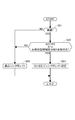
- FIG. 5 shows a flow of processing when the dog clutch 8 is engaged in the clutch control processing executed by the 4WD control unit 34. That is, in the drive mode map of FIG. 3, when the vehicle state transitions from the differential rotation control region (Disconnect) in which the vehicle state is controlled to the disconnect two-wheel drive mode to the driving force distribution region (Connect), and the differential rotation control region (Stand- This is a clutch control process when transitioning to (by). This clutch control process is repeated at a predetermined cycle of about 10 ms to 30 ms.
- step S1 it is determined whether or not there is an engagement request for the dog clutch 8. If there is an engagement request, the process proceeds to step S2, and if there is no engagement request, one process is terminated.
- the engagement request for the dog clutch 8 is made when there is a mode transition request to either the connected four-wheel drive mode or the standby two-wheel drive mode.
- step S2 that proceeds when the dog clutch 8 is requested to be engaged, after the engagement command output of the electric control coupling 16 is performed, the operation proceeds to step S3.
- step S3 the differential rotation ⁇ N between the input / output side meshing members 8a and 8b of the dog clutch 8 is calculated, and then the process proceeds to step S4.
- step S4 it is determined whether or not the differential rotation ⁇ N calculated in step S3 is equal to or less than a preset synchronization determination threshold value ⁇ , that is, whether or not the dog clutch 8 is in a synchronized state. If ⁇ N ⁇ ⁇ (dog clutch synchronization), the process proceeds to step S5. If ⁇ N> ⁇ (dog clutch asynchronous), the process returns to step S2.
- step S5 that proceeds when the dog clutch 8 is determined to be synchronized, the engagement command output of the dog clutch 8 is output, and then the process proceeds to the next step S6.
- the engagement at this time is an engagement for synchronous rotation of the dog clutch 8, and is an engagement with a transmission torque lower than the transmission torque at the time of complete engagement in the connect four-wheel drive mode.
- step S6 it is determined whether or not the dog clutch 8 is completely engaged. When the fastening is completed, the process proceeds to step S7, and when the fastening is not completed, the process returns to step S5.
- the engagement completion determination in step S6 is determined as engagement completion when a stroke exceeding the set amount of the movable member is detected based on detection by the dog clutch stroke sensor 53.
- step S7 that proceeds when the engagement of the dog clutch 8 is completed, it is determined whether or not the drive mode transition based on the drive mode switching map of FIG. 3 is a transition to the connected four-wheel drive mode. In the case of transition to the connected four-wheel drive mode, the process proceeds to step S9, and the electric control coupling 16 is completely fastened, and then one control is finished. In step S7, if it is not the transition to the connected four-wheel drive mode, that is, the transition to the standby two-wheel drive mode, the process proceeds to step S8, and the release command output of the electric control coupling 16 is performed. Then, one control is finished.
- the 4WD control unit 34 includes the synchronous speed control unit 100 as shown in FIG.
- the synchronous speed control unit 100 determines the speed (synchronization) from the start of synchronization to the end of synchronization when the input-side meshing member 8a and the output-side meshing member 8b are rotated synchronously with the engagement of the dog clutch 8. Control.
- the synchronous speed (synchronized) is set to a normal speed (normally synchronized) set in advance during acceleration other than during deceleration and during constant speed travel.
- the synchronous speed (synchronized) is controlled to be lower than the normal speed, and at that time, according to the deceleration, the greater the deceleration is, the lower the speed is controlled.
- step S21 it is determined whether or not the vehicle is in a decelerating state. If the vehicle is in a decelerating state, that is, if the vehicle speed VSP is decreasing, the process proceeds to step S22, and if in a non-decelerating state (accelerated state or constant speed state). The process proceeds to step S24.
- step S24 the sync rate is set to a preset normal sync rate.
- step S23 the synchronization that is the time required for the synchronization of the dog clutch 8 is set to a lower speed (low synchronization) than the normal synchronization.
- step S23 in setting the sync rate, the greater the absolute value of the deceleration, the lower the sync rate (low speed) according to the deceleration when the vehicle state crosses the area division line A in the direction of the arrow C1. Set to).
- the synchronization corresponds to the time required to synchronize the dog clutch 8. The higher the synchronization is, the shorter the time is synchronized, and the lower the synchronization is, the longer the time required for synchronization is set.
- the sync rate is set by the fastening speed of the electric control coupling 16. That is, the lower the synchronization rate, the lower the fastening speed of the electric coupling 16. Conversely, the higher the sync rate, the higher the fastening speed of the electric control coupling 16.
- the fastening command for the electric control coupling 16 is set so that the fastening speed is set fast at the initial stage when the multi-plates are idle, and the fastening speed after the end of the fancy is set according to the deceleration. As shown in FIG. The degree of laying down the fastening command output TETS to the electric coupling 16 is set so that the greater the deceleration, the more laying down.
- FIG. 7 is a time chart showing the operation of a comparative example in which synchronous control of the dog clutch 8 is performed at the same synchronization as that at the time of non-deceleration without performing variable control of the synchronization at the time of deceleration.
- step S2 fastening of the electric control coupling 16 is started (step S2).
- step S2 fastening of the electric control coupling 16 is started (step S2).
- step S2 fastening of the electric control coupling 16.
- the dog clutch 8 When the differential rotation ⁇ N becomes equal to or less than the synchronization determination threshold value ⁇ , the dog clutch 8 is engaged (steps S 2 ⁇ S 3 ⁇ S 4 ⁇ S 5). At this time, in the dog clutch 8, the change in the differential rotation ⁇ N is relatively large, that is, the gradient of the differential rotation ⁇ N is steep as shown in FIG. 7, and when the dog clutch 8 is engaged in this state, the shock at the time of meshing becomes relatively large. Therefore, when the dog clutch 8 is engaged, the acceleration / deceleration G change as shown in the figure occurs. In addition, at this time, the driver is not operating with the foot off the accelerator pedal (not shown), so compared with the time of acceleration when the engine speed increases by depressing the accelerator pedal (not shown). The driver is likely to feel shock.
- the first embodiment it is possible to suppress the occurrence of shock when the dog clutch 8 is engaged.
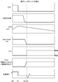
- the operation of the first embodiment will be described based on the time chart of FIG. To do.
- the driver performs the same operation as in FIG. That is, at time t10, the driver depresses an accelerator pedal (not shown) to accelerate the vehicle. After t11, the foot is released from the accelerator pedal (not shown), and the vehicle is in an inertia running state in which the engine brake acts.
- the vehicle speed VSP crosses the set vehicle speed VSP0 that forms the area dividing line A as shown by the arrow C1 in FIG. 3, and the drive mode changes from the disconnect two-wheel drive mode to the connected four-wheel drive. Transition to mode.
- the fastening of the electric control coupling 16 is started (step S2), and in the dog clutch 8, the rotation speed of the output-side meshing member 8b increases.
- the differential rotation ⁇ N between the meshing members 8a and 8b decreases from the time t12 when the fastening of the electric control coupling 16 is started to the time t13.
- the dog clutch 8 is engaged (steps S 2 ⁇ S 3 ⁇ S 4 ⁇ S 5).
- the accelerator opening degree ACC 0 and the vehicle state follows the region dividing line A in the vehicle deceleration state.
- the synchronization is determined according to the deceleration G at that time. In other words, the sync rate is set lower than that during non-deceleration, and the greater the deceleration G, the lower the sync rate.
- the engagement command output TETS of the electric coupling 16 is raised more gently than in the comparative example of FIG. 7, and the decreasing gradient of the differential rotation ⁇ N of the dog clutch 8 becomes gentler than in the comparative example of FIG.
- the fastening command output TETS at this time is the same as during normal running until the actual start of fastening, and then the output corresponding to the stroke amount that actually transmits torque is output. It is suppressed.
- the engagement of the dog clutch 8 is performed in a state where the change in the differential rotation ⁇ N is small, the shock at the time of meshing is suppressed, and the change in the acceleration / deceleration G at that time can be suppressed.
- the time from t12 when the drive mode switching determination is made to t13 when the dog clutch 8 is engaged and the drive mode is actually switched to the connected four-wheel drive mode is as shown in FIG. It becomes longer than the comparative example.
- the reason why the connected four-wheel drive mode is set in the low speed range is to obtain acceleration stability at the time of start-up, and the main purpose of switching to the connect four-wheel drive mode at the time of deceleration is the drive for preparing for the next start-up. Mode switching. Therefore, there is no problem in terms of control even if the engagement timing of the dog clutch 8, that is, the drive mode switching timing is delayed by reducing the synchronization rate.
- the electric coupling 16 when switching from the disconnected two-wheel drive mode to the four-wheel drive mode during acceleration (for example, when the vehicle state transitions as indicated by an arrow C2 in FIG. 3), Set to a normal sync rate higher than when decelerating.
- the sync in this case is, for example, the sync shown in FIG. 7 (rising slope of the engagement command output TETS of the electric control coupling 16). For this reason, it is possible to switch the drive mode with higher control responsiveness than at the time of deceleration, and it is possible to improve acceleration traveling stability at an early stage.
- the driver is depressing the accelerator pedal (not shown), and the engine speed is increased and acceleration G is generated in the vehicle. And it is hard to feel a fastening shock.
- the clutch control device for a four-wheel drive vehicle of the first embodiment is Of the left and right front wheels 6 and 7 and the left and right rear wheels 19 and 20, one is a main drive wheel connected to the engine 1 as a drive source, and the other is a sub drive wheel connected to the engine 1 via a clutch, Of the driving force transmission systems to the left and right rear wheels 19 and 20 as the auxiliary driving wheels, the clutch is divided into a transmission system path on the driving branch side and a transmission system path on the auxiliary driving wheel side with the rear differential 15 interposed therebetween.
- a dog clutch 8 as a meshing clutch and an electric coupling 16 as a friction clutch The dog clutch 8 disconnects the driving force transmission system to the left and right rear wheels 19 and 20 by releasing the clutch from the driving force transmission system to the left and right front wheels 6 and 7, and the electric coupling 16 has a clutch fastening capacity. Accordingly, in a four-wheel drive vehicle that distributes a part of the driving force from the engine 1 to the left and right rear wheels 19 and 20, Engagement / release control of the dog clutch 8 and engagement / release of the electric control coupling 16 according to the vehicle state detected by each of the sensors / switches 35, 36, 38 to 47, 50 to 55 as a vehicle state detection device.
- 4WD control unit 34 is provided as a clutch control unit that can be switched between a disconnect two-wheel drive mode in which both 8 and 16 are released and a connect four-wheel drive mode in which both 8 and 16 are fastened.
- the 4WD control unit 34 shifts from the disconnect two-wheel drive mode to the connect four-wheel drive mode, the synchronization speed that lowers the synchronization speed of the dog clutch 8 when the vehicle is decelerated compared to when the vehicle is not decelerated.
- a control unit 100 is provided.
- the synchronization speed (synchronization) of the dog clutch 8 is set when the vehicle is decelerated compared to when the vehicle is not decelerated. Reduce.
- the change in the differential rotation ⁇ N between the input-side meshing member 8a and the output-side meshing member 8b of the dog clutch 8 can be suppressed as compared with the case where the synchronous speed is not reduced. It is possible to suppress the occurrence of shock during the event. Therefore, adverse effects on the vehicle behavior when the dog clutch 8 is engaged and the sound and vibration of the vehicle can be reduced. Further, by not reducing the synchronous speed except during deceleration, it is possible to ensure drive mode switching control responsiveness during acceleration and the like.
- the clutch control device for the four-wheel drive vehicle of the first embodiment is The 4WD control unit 34 synchronizes the dog clutch 8 at the time of transition from the disconnect two-wheel drive mode to the connect four-wheel drive mode by fastening the electric control coupling 16,
- the synchronization speed control unit 100 is characterized in that the decrease in the synchronization speed is performed by a decrease in the fastening speed of the electric control coupling 16.
- the electric coupling 16 is fastened to transmit the rotation of the left and right rear wheels 19 and 20 as the auxiliary driving wheels to the output side meshing member 8b of the dog clutch 8.
- the dog clutch 8 is synchronized.
- the synchronization speed of the dog clutch 8 can be reduced by lowering the fastening speed of the electric control coupling 16 than the fastening speed at the time of non-deceleration.
- the mechanism can be implemented at a lower cost compared to a mechanism in which the dog clutch 8 is provided with a mechanism and an actuator for adjusting the sync speed to reduce the sync speed.
- the clutch control device for the four-wheel drive vehicle of the first embodiment is The synchronization speed controller 100 reduces the synchronization speed as the vehicle deceleration increases when the synchronization speed decreases.
- the rotational speed change is larger than when the vehicle deceleration is small, so that the shock is likely to increase when the dog clutch 8 is engaged. Therefore, the shock at the time of engagement can be further suppressed by suppressing the change in the differential rotation ⁇ N during synchronization of the dog clutch 8 by decreasing the synchronization speed as the vehicle deceleration is larger. As a result, it is possible to reduce the adverse effects on the vehicle behavior when the dog clutch 8 is engaged and the generation of sound and vibration of the vehicle.
- the clutch control device for the four-wheel drive vehicle of the first embodiment is The 4WD control unit 34 is based on the mode switching map shown in FIG. 3 in which the disconnect two-wheel drive mode and the connect four-wheel drive mode are set according to the accelerator opening ACC and the vehicle speed VSP. Switching between the disconnect two-wheel drive mode and the connect four-wheel drive mode is performed, and a control region for the connect four-wheel drive mode is set in a lower vehicle speed region than the disconnect two-wheel drive mode. And Therefore, when the vehicle decelerates from the disconnect two-wheel drive mode, the mode is switched to the connect four-wheel drive mode, and at this time, the dog clutch 8 is engaged. By reducing the synchronization speed when the dog clutch 8 is engaged, the effect of reducing the shock at the time of engagement can be obtained.
- the clutch control device for a four-wheel drive vehicle of the first embodiment is The dog clutch 8 as the meshing clutch is disposed upstream of the output pinion 10 and the bevel gear 9 as a transfer mechanism provided at the driving branch position to the left and right rear wheels 19 and 20 as auxiliary driving wheels.
- An electric control coupling 16 as a friction clutch includes a bevel gear 9 as a transfer mechanism, an output pinion 10 and a left rear wheel drive shaft 17 from a propeller shaft 12 and a rear differential 15 to a left rear wheel 19 as an auxiliary drive wheel. It is characterized by being arranged at a position. For this reason, in the four-wheel drive vehicle based on the front wheel drive, when the disconnect two-wheel drive mode is selected, friction loss, oil agitation loss, and the like are effectively suppressed, and fuel efficiency can be improved.
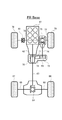
- FIG. 10 shows a drive system configuration of a rear wheel drive-based four-wheel drive vehicle to which the clutch control device is applied.
- the drive system configuration of the four-wheel drive vehicle will be described with reference to FIG.
- the rear wheel drive system of the four-wheel drive vehicle includes a vertical engine 61 (drive source), a transmission 62, a rear propeller shaft 63, a rear differential 64, a left rear wheel drive shaft 65, and a right rear wheel drive.
- a shaft 66, a left rear wheel 67 (main drive wheel), and a right rear wheel 68 (main drive wheel) are provided. That is, the driving force that has passed through the vertical engine 61 and the transmission 62 is transmitted to the left and right rear wheel drive shafts 65 and 66 via the rear propeller shaft 63 and the rear differential 64, and allows the left and right rear wheels 67 while allowing the differential. , 68 are always driven.
- the front wheel drive system of the four-wheel drive vehicle includes an electric control coupling 70 (friction clutch), an input side sprocket 71, an output side sprocket 72, and a chain 73 in a transfer case 69. It is configured. Then, a front propeller shaft 74, a front differential 75, a left front wheel drive shaft 76, a right front wheel drive shaft 77, a left front wheel 78 (sub driving wheel), and a right front wheel 79 (sub driving wheel) connected to the output side sprocket 72. Drive wheel).
- the electric control coupling 70 is disposed in the transfer case 69 at a position upstream of the input side sprocket 71 (position on the main drive system side).
- the drive system rotation rotation of the front propeller shaft 74, etc.
- the electric coupling 70 stops, so that friction loss, oil agitation loss, etc. Suppressed and improved fuel efficiency.
- the dog clutch 8 is arranged on the transmission branch path on the driving branch side with the rear differential 15 interposed therebetween, and the auxiliary driving wheel side In this transmission system, the electric control coupling 16 is arranged separately. For this reason, when there is a fastening request for the dog clutch 8 in the released state, if the fastening control of the electric coupling 16 is performed, the left side gear of the rear differential 15 is restrained by the rotational speed of the left rear wheel 19.
- the rotational speeds of the left and right side gears are constrained, so that the rotational speed of the propeller shaft 12 coupled to the differential case can be reduced. , 20 average rotation speed (driven wheel rotation speed).
- the differential rotation ⁇ N of the dog clutch 8 that has decreased with the passage of time becomes a limit when the differential rotation becomes a certain differential rotation, and thereafter, the differential rotation ⁇ N of the dog clutch 8 increases.
- the differential rotation ⁇ N of the dog clutch 8 increases with the passage of time.
- the electric coupling 70 is arranged on the transmission system path on the driving branch side with the front differential 75 interposed therebetween.
- the dog clutch 80 is arranged separately on the transmission system path on the auxiliary drive wheel side.
- the rotational speed of the right side gear (the right front wheel 79) and the differential case is constrained, so that the rotational speed of the left side gear becomes two rotational speeds. It will be decided by.
- the differential rotation ⁇ N expands in a reverse state. Since other operations are the same as those in the first embodiment, description thereof is omitted.
- the clutch control device for a four-wheel drive vehicle of the second embodiment is The electric coupling 70 as a friction clutch is located upstream of the transfer mechanism (input-side sprocket 71, output-side sprocket 72, chain 73) provided at the driving branch position to the left and right front wheels 78 and 79 as auxiliary driving wheels. Place and The dog clutch 80 as the meshing clutch is disposed at the position of the left front wheel drive shaft 76 from the transfer mechanism to the left front wheel 78 as the auxiliary drive wheel via the propeller shaft and the front differential 75.
- Embodiment 1 shows an example in which the clutch control device of the present invention is applied to a front-wheel drive-based four-wheel drive vehicle (4WD engine vehicle) equipped with an engine as a drive source.
- a front-wheel drive-based four-wheel drive vehicle (4WD engine vehicle) equipped with an engine as a drive source.
- the clutch control device of the present invention is applied to a rear wheel drive-based four-wheel drive vehicle (4WD engine vehicle) whose main drive wheels are left and right rear wheels.
- the present invention can be applied to a four-wheel drive vehicle with a rear wheel drive base in which the disposition relationship between the meshing clutch and the friction clutch is the relationship of the first embodiment.
- the present invention can be applied to a front-wheel drive base four-wheel drive vehicle in which the engagement relationship between the meshing clutch and the friction clutch is the relationship of the second embodiment.
- the clutch control device of the present invention can also be applied to a 4WD hybrid vehicle in which an engine and a motor are mounted as drive sources, and a 4WD electric vehicle in which a motor is mounted as a drive source.
- the two-wheel drive mode is divided into a disconnect two-wheel drive mode and a standby two-wheel drive mode.
- the two-wheel drive mode is a disconnect two-wheel drive mode. You may make it ensure more fuel-consumption as drive mode only.
- the example in which the synchronous speed is variably set according to the deceleration when the synchronous speed is reduced when the vehicle is decelerated is not limited to this.
- the speed is lowered, a constant value may be used.
- the variable setting is made according to the deceleration, as shown in the embodiment, the example in which the setting is made based on the deceleration when crossing the area dividing line is shown, but the present invention is not limited to this. It is not something.
- the deceleration may be read every predetermined control cycle, and the synchronization speed may be changed every moment according to the read deceleration.
- other well-known friction clutches such as a single plate can be used as the friction clutch.
Landscapes
- Engineering & Computer Science (AREA)
- Mechanical Engineering (AREA)
- Transportation (AREA)
- Chemical & Material Sciences (AREA)
- Combustion & Propulsion (AREA)
- General Engineering & Computer Science (AREA)
- Automation & Control Theory (AREA)
- Physics & Mathematics (AREA)
- Mathematical Physics (AREA)
- Fluid Mechanics (AREA)
- Arrangement And Mounting Of Devices That Control Transmission Of Motive Force (AREA)
- Arrangement And Driving Of Transmission Devices (AREA)
Abstract
Description
この4輪駆動車では、2輪駆動モードから4輪駆動モードへの切り替え時には、摩擦クラッチを締結し、噛み合いクラッチの駆動源側と後輪側とを同期させた後、噛み合いクラッチを締結する。また、4輪駆動モードから2輪駆動モードへの切り替え時には、摩擦クラッチを解放した後、噛み合いクラッチを解放する。
また、逆に、常に、同期速度を締結時にショックが生じないように遅くした場合、制御応答性が悪化し、特に、車両挙動を安定させたい加速時における制御応答遅れが問題となる。
駆動源と副駆動輪との間に介在されたクラッチとして、前記副駆動輪への駆動力伝達系のうち、デファレンシャルを挟んだ駆動分岐側の伝達系路と副駆動輪側の伝達系路にそれぞれ分けて配置される噛み合いクラッチと摩擦クラッチとを備え、
噛み合いクラッチ及び摩擦クラッチの締結及び解放を制御するクラッチコントロールユニットに、両クラッチを解放したディスコネクト2輪駆動モードから、両クラッチを締結させた4輪駆動モードへの移行時において、車両減速時は非減速時と比較して、噛み合いクラッチの同期速度を低下させる同期速度制御部を設けたことを特徴とする4輪駆動車のクラッチ制御装置とした。
一方、クラッチコントロールユニットは、非減速時に噛み合いクラッチを締結する場合、減速時と比較して噛み合いクラッチの同期速度を高く制御する。これにより、加速時などの非減速時の噛み合いクラッチの締結タイミングが、減速時と比較して早くなり、制御応答性を高め、車両挙動の安定性向上を図ることが可能となる。
(実施の形態1)
まず、実施の形態1の構成を説明する。
実施の形態1における前輪駆動ベースの4輪駆動車(4輪駆動車の一例)のクラッチ制御装置の構成を、「4輪駆動車の駆動系構成」、「4輪駆動車の制御系構成」、「駆動モード切替構成」、「クラッチ制御構成」に分けて説明する。
図1は、実施の形態1のクラッチ制御装置が適用された前輪駆動ベースの4輪駆動車の駆動系構成を示す。以下、図1に基づき、4輪駆動車の駆動系構成を説明する。
また、図2に示すドグクラッチ8の入力側噛み合い部材8aは、フロントデファレンシャル3のデフケース3aに連結され、ドグクラッチ8の出力側噛み合い部材8bは、ベベルギア9に連結されている。
そして、電制カップリング16の入力側クラッチプレートは、リアデファレンシャル15の左サイドギアに連結され、出力側クラッチプレートは、左後輪ドライブシャフト17に連結されている。
図2は、実施の形態1のクラッチ制御装置が適用された前輪駆動ベースの4輪駆動車の制御系構成を示す。以下、図2に基づき、4輪駆動車の制御系構成を説明する。
「2WDモード」が選択されると、ドグクラッチ8と電制カップリング16を解放した前輪駆動の2WD状態が維持される。
「ロックモード」が選択されると、ドグクラッチ8と電制カップリング16を締結した完全4WD状態が維持される。
図3は、「オートモード」が選択されたときのクラッチ制御で用いられる車速VSPとアクセル開度ACCに応じた駆動モード切替マップを示し、図4は、駆動モード(ディスコネクト2輪駆動モード・スタンバイ2輪駆動モード・コネクト4輪駆動モード)の切り替え遷移を示す。以下、図3および図4に基づき、駆動モード切り替え構成を説明する。
図5は、4WDコントロールユニット34にて実行されるクラッチ制御処理のうち、ドグクラッチ8を締結させる際の処理の流れを示している。すなわち、図3の駆動モードマップにおいて、車両状態がディスコネクト2輪駆動モードに制御する差回転制御領域(Disconnect)から、駆動力配分領域(Connect)に遷移した場合および差回転制御領域(Stand-by)に遷移した場合のクラッチ制御処理である。なお、このクラッチ制御処理は、10ms~30ms程度の所定の周期で繰り返される。
ステップS1では、ドグクラッチ8に対し締結要求があるか否か判定し、この締結要求がある場合はステップS2に進み、締結要求が無い場合は1回の処理を終了する。なお、このドグクラッチ8に対する締結要求は、コネクト4輪駆動モードとスタンバイ2輪駆動モードとのいずれかへのモード遷移要求がある場合に成される。
続くステップS3では、ドグクラッチ8の入出力側噛み合い部材8a,8bの差回転ΔNの演算を行った後、ステップS4に進む。
ステップS6では、ドグクラッチ8の締結が完了したか否か判定する。そして、締結完了の場合はステップS7に進み、締結未完了の場合はステップS5に戻る。なお、ステップS6の締結完了判定は、ドグクラッチストロークセンサ53の検出に基づいて、可動部材の設定量を超えるストロークを検出した場合に締結完了と判定する。
次に、ステップS2において電制カップリングの締結指令出力を行う場合の締結速度制御に基づく、ドグクラッチ8の同期速度の制御について説明する。
すなわち、本実施の形態1では、図2に示すように4WDコントロールユニット34は、同期速度制御部100を備えている。そして、この同期速度制御部100は、ドグクラッチ8の締結に伴い入力側噛み合い部材8aと出力側噛み合い部材8bとを同期回転させる際に、同期開始から同期終了となるまでの速度(シンクロレイト)を制御する。また、この同期速度(シンクロレイト)は、減速時以外の加速時および一定速走行時は、予め設定された通常速度(通常シンクロレイト)とする。一方、車両減速時は、同期速度(シンクロレイト)を、通常速度よりも低速に制御し、かつ、その際、減速度に応じ、減速度が大きいほど低速に制御する。
まず、ステップS21では、車両が減速状態であるか否か判定し、減速状態、すなわち車速VSPが低下している場合はステップS22に進み、非減速状態(加速状態あるいは一定速状態)の場合は、ステップS24に進む。
一方、ステップS23では、ドグクラッチ8の同期に要する時間であるシンクロレイトを、通常シンクロレイトよりも低速(低シンクロレイト)に設定する。さらに、ステップS23では、シンクロレイトを設定するのにあたり、車両状態が領域区分線Aを矢印C1方向に横切った際の減速度に応じ、減速度の絶対値が大きいほど、シンクロレイトを低下(低速に設定)する。
シンクロレイトは、ドグクラッチ8を同期させるのに要する時間に相当し、シンクロレイトが高いほど、短時間に同期させ、シンクロレイトが低いほど、同期に要する時間を長く設定する。
次に、実施の形態1の作用を、図7、図8のタイムチャートに基づいて説明する。
まず、実施の形態1の作用の説明に先立ち、本実施の形態との比較例の作用について説明する。
そして、差回転ΔNが、同期判定閾値α以下となると、ドグクラッチ8の締結が行なわれる(ステップS2→S3→S4→S5)。
このとき、ドグクラッチ8では、差回転ΔNの変化が相対的に大きく、すなわち、図7に示すように差回転ΔNの低下勾配が急であり、この状態でドグクラッチ8を締結すると、噛み合い時のショックが相対的に大きくなる。したがって、ドグクラッチ8の締結時に、図示のような加減速G変化が生じる。加えて、このとき、運転者は図外のアクセルペダルから足を離して操作を行っていない状態であるため、図外のアクセルペダルの踏み込みを行ってエンジン回転数が上昇する加速時と比較して、運転者はショックを感じやすい。
すなわち、t10の時点では、運転者は図外のアクセルペダルを踏み込んで車両を加速させている。そして、t11の時点以降、図外のアクセルペダルから足を離し、車両はエンジンブレーキが作用する惰性走行状態となっている。
そして、差回転ΔNが、同期判定閾値α以下となると、ドグクラッチ8の締結が行なわれる(ステップS2→S3→S4→S5)。
なお、この場合、図示のように、駆動モードの切り替え判定がなされたt12の時点から、ドグクラッチ8が締結されて実際に駆動モードがコネクト4輪駆動モードに切り替えられるt13までの時間は、図7の比較例よりも長くなる。
しかしながら、そもそも、低速域でコネクト4輪駆動モードとしているのは、発進時の加速安定性を得るためであり、減速時にコネクト4輪駆動モードに切り替える主たる目的は、次の発進時に備えるための駆動モードの切り替えである。
よって、シンクロレイトを下げることにより、ドグクラッチ8の締結タイミング、すなわち、駆動モードの切り替えタイミングが遅れても、制御上は問題ない。
このため、減速時よりも高い制御応答性で、駆動モードの切り替えを行うことができ、早期に、加速走行安定性を高めることができる。また、加速時には、運転者は、図外のアクセルペダルを踏み込む操作を行っており、また、エンジン回転も上昇して車両に加速Gが発生した状態であるため、運転者は、減速時と比較して、締結ショックを感じにくい。
以下に、実施の形態1の4輪駆動車のクラッチ制御装置の効果を作用と共に列挙する。
1)実施の形態1の4輪駆動車のクラッチ制御装置は、
左右前輪6,7と左右後輪19,20のうち、一方を駆動源としてのエンジン1に接続される主駆動輪とし、他方を前記エンジン1にクラッチを介して接続される副駆動輪とし、
前記クラッチとして、前記副駆動輪としての左右後輪19,20への駆動力伝達系のうち、リアデファレンシャル15を挟んだ駆動分岐側の伝達系路と副駆動輪側の伝達系路にそれぞれ分けて配置される噛み合いクラッチとしてのドグクラッチ8と摩擦クラッチとしての電制カップリング16とを備え、
前記ドグクラッチ8は、クラッチ解放により前記左右後輪19,20への駆動力伝達系を、前記左右前輪6,7への駆動力伝達系から切り離し、前記電制カップリング16は、クラッチ締結容量に応じて前記エンジン1からの駆動力の一部を前記左右後輪19,20へ配分する4輪駆動車において、
車両状態検出装置としての各センサ・スイッチ類35,36,38~47、50~55が検出する車両状態に応じて、前記ドグクラッチ8の締結/解放制御と前記電制カップリング16の締結/解放制御とを行い、両者8,16を解放したディスコネクト2輪駆動モードと両者8,16を締結したコネクト4輪駆動モードとに切替可能なクラッチコントロールユニットとしての4WDコントロールユニット34を設け、
前記4WDコントロールユニット34に、前記ディスコネクト2輪駆動モードから前記コネクト4輪駆動モードへの移行時において、車両減速時は非減速時と比較して、前記ドグクラッチ8の同期速度を低下させる同期速度制御部100を設けたことを特徴とする。
このように、本実施の形態1では、ディスコネクト2輪駆動モードからコネクト4輪駆動モードに切り替えるのにあたり、車両減速時には、非減速時と比較して、ドグクラッチ8の同期速度(シンクロレート)を低下させる。
したがって、車両減速時には、同期速度の低下を行わない場合と比較して、ドグクラッチ8の入力側噛み合い部材8aと出力側噛み合い部材8bとの差回転ΔNの変化を抑えることができ、これにより、締結の際のショックの発生を抑えることができる。よって、ドグクラッチ8の締結時の車両挙動への悪影響や車両の音・振動を低減させることができる。また、減速時以外は、同期速度の低減を行わないことにより、加速時などにおける駆動モード切替制御応答性を確保することができる。
前記4WDコントロールユニット34は、前記ディスコネクト2輪駆動モードから前記コネクト4輪駆動モードへの移行時の前記ドグクラッチ8の同期は、前記電制カップリング16の締結により行い、
前記同期速度制御部100は、前記同期速度の低下は、前記電制カップリング16の締結速度の低下により実行することを特徴とする。
本実施の形態1では、ドグクラッチ8の締結時には、電制カップリング16を締結させて、副駆動輪である左右後輪19,20の回転を、ドグクラッチ8の出力側噛み合い部材8bに伝達させることにより、ドグクラッチ8の同期を行う。
したがって、電制カップリング16の締結速度を、非減速時の締結速度よりも低下させることにより、ドグクラッチ8の同期速度を低下させることができる。このため、ドグクラッチ8にシンクロ速度を調節する機構やアクチュエータを設けてシンクロ速度を低減させるものと比較して、低コストで実行可能である。
前記同期速度制御部100は、アクセル開度ACCが零での減速時に前記同期速度を低下させることを特徴とする。
車両減速時に同期速度を低下する際の条件に、アクセル開度ACC=0を加えたため、登坂時など、アクセルペダルを踏んだ状態で減速が生じた場合には、同期速度を低下させる制御は行なわない。
これにより、登坂時などアクセルペダルを踏み込んだ状態では、ディスコネクト2輪駆動モードからコネクト4輪駆動モードへの切り替えを高応答性で行なって、走行安定性を確保することができる。
前記同期速度制御部100は、前記同期速度の低下時には、車両減速度が大きいほど、前記同期速度を低下させることを特徴とする。
車両減速度が大きい場合、車両減速度が小さい場合よりも、回転速度変化が大きいため、ドグクラッチ8の締結時にショックが大きくなりやすい。そこで、車両減速度が大きいほど、同期速度を低下させることにより、ドグクラッチ8の同期時の差回転ΔNの変化を抑えることにより、締結時のショックをいっそう抑制することができる。これにより、ドグクラッチ8の締結時の車両挙動への悪影響や、車両の音・振動の発生を低減させることが可能となった。
前記4WDコントロールユニット34は、前記アクセル開度ACCと車速VSPとに応じて前記ディスコネクト2輪駆動モードと前記コネクト4輪駆動モードとが設定された図3に示すモード切替マップに基づいて、前記ディスコネクト2輪駆動モードと前記コネクト4輪駆動モードとの切替を行い、かつ、前記ディスコネクト2輪駆動モードよりも低車速領域に前記コネクト4輪駆動モードへの制御領域を設定したことを特徴とする。
したがって、ディスコネクト2輪駆動モードからの車両減速時には、コネクト4輪駆動モードに切り替えられ、この際に、ドグクラッチ8の締結が実行される。このドグクラッチ8の締結時に、同期速度を低下させることにより、上記の締結時のショックを低減する効果を得ることができる。
噛み合いクラッチとしてのドグクラッチ8は、副駆動輪としての左右後輪19,20への駆動分岐位置に設けたトランスファ機構としてのベベルギア9、出力ピニオン10より上流位置に配置し、
摩擦クラッチとしての電制カップリング16は、トランスファ機構としてのベベルギア9、出力ピニオン10からプロペラシャフト12およびリアデファレンシャル15を経由した副駆動輪としての左後輪19への左後輪ドライブシャフト17の位置に配置したことを特徴とする。
このため、前輪駆動ベースの4輪駆動車において、ディスコネクト2輪駆動モードが選択されているとき、フリクション損失やオイル攪拌損失などが有効に抑えられ、燃費向上を達成することができる。
実施の形態2のクラッチ制御装置は、後輪駆動ベースの4輪駆動車に適用し、デファレンシャルを挟んだ噛み合いクラッチと摩擦クラッチの配置関係を、実施の形態1とは逆の配置関係にした例である。
すなわち、電制カップリング70とドグクラッチ80を共に解放する2輪駆動モード(=ディスコネクト2輪駆動モード)を選択することが可能な駆動系構成としている。この電制カップリング70とドグクラッチ80を解放することにより、電制カップリング70より下流側の駆動系回転(フロントプロペラシャフト74等の回転)が停止することで、フリクション損失やオイル攪拌損失などが抑えられ、燃費向上が達成される。
実施の形態1では、副駆動輪である左右後輪19,20への駆動力伝達系のうち、リアデファレンシャル15を挟んだ駆動分岐側の伝達系路にドグクラッチ8を配置し、副駆動輪側の伝達系路に電制カップリング16にそれぞれ分けて配置した構成としている。
このため、解放状態のドグクラッチ8に対する締結要求があるとき、電制カップリング16の締結制御を行うと、リアデファレンシャル15の左側サイドギアが左後輪19の回転数により拘束される。
しかし、左右前輪6,7がスリップ状態のときは、時間の経過と共に減少していたドグクラッチ8の差回転ΔNが、ある差回転になると限界になり、その後、ドグクラッチ8の差回転ΔNは増加へ移行し、時間の経過と共にドグクラッチ8の差回転ΔNが拡大する。
このため、解放状態のドグクラッチ80に対する締結要求があるとき、電制カップリング70の締結制御を行うと、フロントデファレンシャル75のデフケースがリアプロペラシャフト63の回転数により拘束される。
この結果、左右後輪67,68が非スリップ状態のときは、ドグクラッチ80の差回転ΔNがΔN=0になる。
しかし、左右後輪67,68がスリップ状態のときは、時間の経過と共に減少していたドグクラッチ80の差回転ΔNが、ΔN=0(ゼロ)を跨いで逆転してしまい、その後、ドグクラッチ80の差回転ΔNは逆転した状態で拡大してゆくことになる。なお、他の作用は、実施の形態1と同様であるので、説明を省略する。
実施の形態2の4輪駆動車のクラッチ制御装置にあっては、下記の効果を得ることができる。
2-1) 実施の形態2の4輪駆動車のクラッチ制御装置は、
摩擦クラッチとしての電制カップリング70は、副駆動輪としての左右前輪78,79への駆動分岐位置に設けたトランスファ機構(入力側スプロケット71、出力側スプロケット72、チェーン73)よりも上流位置に配置し、
噛み合いクラッチとしてのドグクラッチ80は、トランスファ機構からプロペラシャフトおよびフロントデファレンシャル75を経由した副駆動輪としての左前輪78への左前輪ドライブシャフト76の位置に配置した。
このため、上記1)~5)の効果に加え、後輪駆動ベースの4輪駆動車において、ディスコネクト2輪駆動モードが選択されているとき、フリクション損失やオイル攪拌損失などが有効に抑えられ、燃費向上を達成することができる。
また、実施の形態1では、2輪駆動モードを、ディスコネクト2輪駆動モードと、スタンバイ2輪駆動モードとに分けたが、2輪駆動モードは、図9に示すように、ディスコネクト2輪駆動モードのみとして、より燃費性を確保するようにしてもよい。
また、実施の形態では、車両減速時に同期速度を低下させるのにあたり、減速度に応じて同期速度を可変設定する例を示したが、これに限定されるものではなく、非減速時よりも同期速度を低くするのであれば、一定値を用いるようにしてもよい。
また、減速度に応じて可変設定する場合にあっても、実施の形態で示したように、領域区分線を横切った際の減速度に基づいて設定する例を示したが、これに限定されるものではない。例えば、所定の制御周期ごとに減速度を読み込んで、その読み込んだ減速度に応じ、同期速度を刻々と変化させるようにしてもよい。
また、摩擦クラッチとしては、実施の形態で示した多板摩擦クラッチ以外にも、単板のものなど、他の周知の摩擦クラッチを用いることができる。
Claims (7)
- 左右前輪と左右後輪のうち、一方を駆動源に接続される主駆動輪とし、他方を前記駆動源にクラッチを介して接続される副駆動輪とし、
前記クラッチとして、前記副駆動輪への駆動力伝達系のうち、デファレンシャルを挟んだ駆動分岐側の伝達系路と副駆動輪側の伝達系路にそれぞれ分けて配置される噛み合いクラッチと摩擦クラッチとを備え、
前記噛み合いクラッチは、クラッチ解放により前記副駆動輪への駆動力伝達系を、前記主駆動輪への駆動力伝達系から切り離し、前記摩擦クラッチは、クラッチ締結容量に応じて前記駆動源からの駆動力の一部を前記副駆動輪へ配分する4輪駆動車において、
車両状態検出装置が検出する車両状態に応じて、前記噛み合いクラッチの締結/解放制御と前記摩擦クラッチの締結/解放制御とを行い、両クラッチを解放したディスコネクト2輪駆動モードと両クラッチを締結した4輪駆動モードとに切替可能なクラッチコントロールユニットを設け、
前記クラッチコントロールユニットに、前記ディスコネクト2輪駆動モードから前記4輪駆動モードへの移行時において、車両減速時は非減速時と比較して、前記噛み合いクラッチの同期速度を低下させる同期速度制御部を設けたことを特徴とする4輪駆動車のクラッチ制御装置。 - 請求項1に記載の4輪駆動車のクラッチ制御装置において、
前記クラッチコントロールユニットは、前記ディスコネクト2輪駆動モードから前記4輪駆動モードへの移行時の前記噛み合いクラッチの同期は、前記摩擦クラッチの締結により行い、
前記同期速度制御部は、前記同期速度の低下は、前記摩擦クラッチの締結速度の低下により実行することを特徴とする4輪駆動車のクラッチ制御装置。 - 請求項1または請求項2に記載の4輪駆動車のクラッチ制御装置において、
前記同期速度制御部は、アクセル開度が零での減速時に前記同期速度を低下させることを特徴とする4輪駆動車のクラッチ制御装置。 - 請求項1~請求項3のいずれか1項に記載の4輪駆動車のクラッチ制御装置において、
前記同期速度制御部は、前記同期速度の低下時には、車両減速度が大きいほど、前記同期速度を低下させることを特徴とする4輪駆動車のクラッチ制御装置。 - 請求項1~請求項4のいずれか1項に記載の4輪駆動車のクラッチ制御装置において、
前記クラッチコントロールユニットは、前記アクセル開度と車速とに応じて前記ディスコネクト2輪駆動モードと前記4輪駆動モードとが設定されたモード切替マップに基づいて、前記ディスコネクト2輪駆動モードと前記4輪駆動モードとの切替を行い、かつ、前記ディスコネクト2輪駆動モードよりも低車速領域に前記4輪駆動モードへの制御領域を設定したことを特徴とする4輪駆動車のクラッチ制御装置。 - 請求項1~請求項5のいずれか一項に記載された4輪駆動車のクラッチ制御装置において、
前記噛み合いクラッチは、前記副駆動輪への駆動分岐位置に設けたトランスファ機構より上流位置に配置し、
前記摩擦クラッチは、前記トランスファ機構からプロペラシャフトおよびデファレンシャルを経由した前記副駆動輪へのドライブシャフトの位置に配置したことを特徴とする4輪駆動車のクラッチ制御装置。 - 請求項1~請求項5のいずれか一項に記載された4輪駆動車のクラッチ制御装置において、
前記摩擦クラッチは、前記副駆動輪への駆動分岐位置に設けたトランスファ機構より上流位置に配置し、
前記噛み合いクラッチは、前記トランスファ機構からプロペラシャフトおよびデファレンシャルを経由した前記副駆動輪へのドライブシャフトの位置に配置したことを特徴とする4輪駆動車のクラッチ制御装置。
Priority Applications (4)
| Application Number | Priority Date | Filing Date | Title |
|---|---|---|---|
| JP2016505232A JP6179661B2 (ja) | 2014-02-28 | 2015-02-24 | 4輪駆動車のクラッチ制御装置 |
| US15/118,148 US9783053B2 (en) | 2014-02-28 | 2015-02-24 | Clutch control device for 4-wheel drive vehicle |
| EP15755987.3A EP3112204B1 (en) | 2014-02-28 | 2015-02-24 | Clutch control device for 4-wheel drive vehicle |
| CN201580010785.3A CN106103174B (zh) | 2014-02-28 | 2015-02-24 | 4轮驱动车的离合器控制装置 |
Applications Claiming Priority (2)
| Application Number | Priority Date | Filing Date | Title |
|---|---|---|---|
| JP2014-038479 | 2014-02-28 | ||
| JP2014038479 | 2014-02-28 |
Publications (1)
| Publication Number | Publication Date |
|---|---|
| WO2015129691A1 true WO2015129691A1 (ja) | 2015-09-03 |
Family
ID=54009009
Family Applications (1)
| Application Number | Title | Priority Date | Filing Date |
|---|---|---|---|
| PCT/JP2015/055246 WO2015129691A1 (ja) | 2014-02-28 | 2015-02-24 | 4輪駆動車のクラッチ制御装置 |
Country Status (5)
| Country | Link |
|---|---|
| US (1) | US9783053B2 (ja) |
| EP (1) | EP3112204B1 (ja) |
| JP (1) | JP6179661B2 (ja) |
| CN (1) | CN106103174B (ja) |
| WO (1) | WO2015129691A1 (ja) |
Cited By (2)
| Publication number | Priority date | Publication date | Assignee | Title |
|---|---|---|---|---|
| EP3192690A1 (de) * | 2016-01-14 | 2017-07-19 | ZF Friedrichshafen AG | Verfahren zum überwachen einer differentialsperre |
| JP2019026151A (ja) * | 2017-08-01 | 2019-02-21 | トヨタ自動車株式会社 | 4輪駆動車両の駆動状態切換装置 |
Families Citing this family (13)
| Publication number | Priority date | Publication date | Assignee | Title |
|---|---|---|---|---|
| GB201319641D0 (en) * | 2013-11-07 | 2013-12-25 | Jaguar Land Rover Ltd | Driveline and method of controlling a driveline |
| CN106232411B (zh) * | 2014-04-11 | 2018-09-28 | 日产自动车株式会社 | 四轮驱动车的离合器控制装置 |
| JP6135634B2 (ja) * | 2014-10-07 | 2017-05-31 | トヨタ自動車株式会社 | 車両用トランスファ |
| CA2917373A1 (en) * | 2016-01-12 | 2017-07-12 | 2Low | Two wheel drive low range devices and systems |
| IL296644B2 (en) * | 2016-06-14 | 2023-12-01 | Polaris Inc | Hybrid vehicle |
| US10150480B2 (en) * | 2016-12-12 | 2018-12-11 | Ford Global Technologies, Llc | Vehicle all-wheel drive control system |
| JP6705372B2 (ja) * | 2016-12-27 | 2020-06-03 | アイシン・エィ・ダブリュ株式会社 | 動力伝達制御装置 |
| RU2719104C1 (ru) | 2017-04-04 | 2020-04-17 | Ниссан Мотор Ко., Лтд. | Способ управления сцеплением транспортного средства с приводом на четыре колеса и устройство управления сцеплением |
| DE102019201945B4 (de) * | 2019-02-14 | 2023-07-20 | Audi Ag | Antriebsvorrichtung für eine Fahrzeugachse eines Fahrzeugs |
| US11370266B2 (en) | 2019-05-16 | 2022-06-28 | Polaris Industries Inc. | Hybrid utility vehicle |
| DE102019133643A1 (de) | 2019-12-10 | 2021-06-10 | Audi Ag | Verfahren zum Betreiben eines Fahrzeugs sowie Fahrzeug |
| DE102020120375A1 (de) | 2020-08-03 | 2022-02-03 | Bayerische Motoren Werke Aktiengesellschaft | Kraftfahrzeugantriebshinterachse |
| US20230399003A1 (en) * | 2022-06-08 | 2023-12-14 | Ford Global Technologies, Llc | Powertrain torque control during shift to four-wheel drive in automated-driving mode |
Citations (4)
| Publication number | Priority date | Publication date | Assignee | Title |
|---|---|---|---|---|
| JPS6030433A (ja) * | 1983-07-29 | 1985-02-16 | Mazda Motor Corp | エンジンの制御装置 |
| JP2002370557A (ja) * | 2001-06-15 | 2002-12-24 | Tochigi Fuji Ind Co Ltd | 4輪駆動システム |
| JP2004009954A (ja) * | 2002-06-10 | 2004-01-15 | Toyota Motor Corp | 四輪駆動車の動力伝達装置 |
| JP2011143790A (ja) * | 2010-01-13 | 2011-07-28 | Jtekt Corp | 駆動力伝達装置及びその制御方法 |
Family Cites Families (10)
| Publication number | Priority date | Publication date | Assignee | Title |
|---|---|---|---|---|
| AU2120997A (en) * | 1996-02-13 | 1997-09-02 | New Venture Gear, Inc. | Full-time transfer case with synchronized gear reduction unit |
| DE102009005378C5 (de) * | 2008-10-13 | 2018-06-21 | Magna powertrain gmbh & co kg | Antriebsstrang für ein Kraftfahrzeug |
| JP2010254058A (ja) | 2009-04-23 | 2010-11-11 | Univance Corp | 4輪駆動車用駆動力伝達装置 |
| JP2011079421A (ja) * | 2009-10-07 | 2011-04-21 | Univance Corp | 4輪駆動車用駆動力伝達装置 |
| CN102189928A (zh) | 2010-03-14 | 2011-09-21 | 贾新成 | 一种节油的汽车四驱系统 |
| US8720633B2 (en) * | 2010-09-28 | 2014-05-13 | Ford Global Technologies, Llc | All wheel drive speed synchronization and connection |
| CN102166947B (zh) | 2011-03-10 | 2013-05-01 | 上海交通大学 | 多模无级变速混合动力驱动系统 |
| JP5849770B2 (ja) | 2012-02-29 | 2016-02-03 | 株式会社ジェイテクト | 四輪駆動車、及び四輪駆動車の制御装置 |
| JP5926113B2 (ja) * | 2012-05-15 | 2016-05-25 | Gknドライブラインジャパン株式会社 | 自動車の駆動系装置 |
| KR20140005402A (ko) | 2012-07-03 | 2014-01-15 | 현대모비스 주식회사 | 4륜 구동 하이브리드 차량의 구동제어방법 |
-
2015
- 2015-02-24 JP JP2016505232A patent/JP6179661B2/ja not_active Expired - Fee Related
- 2015-02-24 EP EP15755987.3A patent/EP3112204B1/en not_active Not-in-force
- 2015-02-24 US US15/118,148 patent/US9783053B2/en active Active
- 2015-02-24 CN CN201580010785.3A patent/CN106103174B/zh not_active Expired - Fee Related
- 2015-02-24 WO PCT/JP2015/055246 patent/WO2015129691A1/ja active Application Filing
Patent Citations (4)
| Publication number | Priority date | Publication date | Assignee | Title |
|---|---|---|---|---|
| JPS6030433A (ja) * | 1983-07-29 | 1985-02-16 | Mazda Motor Corp | エンジンの制御装置 |
| JP2002370557A (ja) * | 2001-06-15 | 2002-12-24 | Tochigi Fuji Ind Co Ltd | 4輪駆動システム |
| JP2004009954A (ja) * | 2002-06-10 | 2004-01-15 | Toyota Motor Corp | 四輪駆動車の動力伝達装置 |
| JP2011143790A (ja) * | 2010-01-13 | 2011-07-28 | Jtekt Corp | 駆動力伝達装置及びその制御方法 |
Non-Patent Citations (1)
| Title |
|---|
| See also references of EP3112204A4 * |
Cited By (2)
| Publication number | Priority date | Publication date | Assignee | Title |
|---|---|---|---|---|
| EP3192690A1 (de) * | 2016-01-14 | 2017-07-19 | ZF Friedrichshafen AG | Verfahren zum überwachen einer differentialsperre |
| JP2019026151A (ja) * | 2017-08-01 | 2019-02-21 | トヨタ自動車株式会社 | 4輪駆動車両の駆動状態切換装置 |
Also Published As
| Publication number | Publication date |
|---|---|
| EP3112204A1 (en) | 2017-01-04 |
| US9783053B2 (en) | 2017-10-10 |
| EP3112204B1 (en) | 2018-07-25 |
| CN106103174B (zh) | 2018-01-09 |
| JP6179661B2 (ja) | 2017-08-16 |
| JPWO2015129691A1 (ja) | 2017-03-30 |
| EP3112204A4 (en) | 2017-05-03 |
| US20170166052A1 (en) | 2017-06-15 |
| CN106103174A (zh) | 2016-11-09 |
Similar Documents
| Publication | Publication Date | Title |
|---|---|---|
| JP6179661B2 (ja) | 4輪駆動車のクラッチ制御装置 | |
| JP6179662B2 (ja) | 4輪駆動車のクラッチ制御装置 | |
| JP6288242B2 (ja) | 4輪駆動車のクラッチ制御装置 | |
| JP6115682B2 (ja) | 4輪駆動車のクラッチ制御装置 | |
| JP6123942B2 (ja) | 4輪駆動車のクラッチ制御装置 | |
| JP6112256B2 (ja) | 4輪駆動車のクラッチ制御装置 | |
| WO2015156161A1 (ja) | 4輪駆動車のクラッチ制御装置 | |
| JP6379691B2 (ja) | 4輪駆動車のクラッチ制御装置 | |
| JP6303822B2 (ja) | 4輪駆動車のクラッチ制御装置 | |
| JP6398360B2 (ja) | 4輪駆動車のクラッチ制御装置 | |
| JP6379685B2 (ja) | 4輪駆動車のクラッチ制御装置 | |
| JP6221830B2 (ja) | 4輪駆動車のクラッチ制御装置 | |
| JP2016034812A (ja) | 4輪駆動車の噛み合いクラッチ | |
| JP2021079779A (ja) | 車両用トルク制御装置 |
Legal Events
| Date | Code | Title | Description |
|---|---|---|---|
| 121 | Ep: the epo has been informed by wipo that ep was designated in this application |
Ref document number: 15755987 Country of ref document: EP Kind code of ref document: A1 |
|
| ENP | Entry into the national phase |
Ref document number: 2016505232 Country of ref document: JP Kind code of ref document: A |
|
| WWE | Wipo information: entry into national phase |
Ref document number: 15118148 Country of ref document: US |
|
| NENP | Non-entry into the national phase |
Ref country code: DE |
|
| REEP | Request for entry into the european phase |
Ref document number: 2015755987 Country of ref document: EP |
|
| WWE | Wipo information: entry into national phase |
Ref document number: 2015755987 Country of ref document: EP |