WO2015122247A1 - ガス供給装置、水素ステーション及びガス供給方法 - Google Patents
ガス供給装置、水素ステーション及びガス供給方法 Download PDFInfo
- Publication number
- WO2015122247A1 WO2015122247A1 PCT/JP2015/051470 JP2015051470W WO2015122247A1 WO 2015122247 A1 WO2015122247 A1 WO 2015122247A1 JP 2015051470 W JP2015051470 W JP 2015051470W WO 2015122247 A1 WO2015122247 A1 WO 2015122247A1
- Authority
- WO
- WIPO (PCT)
- Prior art keywords
- gas
- compressor
- pressure
- accumulator
- gas supply
- Prior art date
Links
Images


Classifications
-
- F—MECHANICAL ENGINEERING; LIGHTING; HEATING; WEAPONS; BLASTING
- F17—STORING OR DISTRIBUTING GASES OR LIQUIDS
- F17C—VESSELS FOR CONTAINING OR STORING COMPRESSED, LIQUEFIED OR SOLIDIFIED GASES; FIXED-CAPACITY GAS-HOLDERS; FILLING VESSELS WITH, OR DISCHARGING FROM VESSELS, COMPRESSED, LIQUEFIED, OR SOLIDIFIED GASES
- F17C5/00—Methods or apparatus for filling containers with liquefied, solidified, or compressed gases under pressures
- F17C5/06—Methods or apparatus for filling containers with liquefied, solidified, or compressed gases under pressures for filling with compressed gases
-
- F—MECHANICAL ENGINEERING; LIGHTING; HEATING; WEAPONS; BLASTING
- F17—STORING OR DISTRIBUTING GASES OR LIQUIDS
- F17C—VESSELS FOR CONTAINING OR STORING COMPRESSED, LIQUEFIED OR SOLIDIFIED GASES; FIXED-CAPACITY GAS-HOLDERS; FILLING VESSELS WITH, OR DISCHARGING FROM VESSELS, COMPRESSED, LIQUEFIED, OR SOLIDIFIED GASES
- F17C13/00—Details of vessels or of the filling or discharging of vessels
- F17C13/04—Arrangement or mounting of valves
-
- F—MECHANICAL ENGINEERING; LIGHTING; HEATING; WEAPONS; BLASTING
- F17—STORING OR DISTRIBUTING GASES OR LIQUIDS
- F17C—VESSELS FOR CONTAINING OR STORING COMPRESSED, LIQUEFIED OR SOLIDIFIED GASES; FIXED-CAPACITY GAS-HOLDERS; FILLING VESSELS WITH, OR DISCHARGING FROM VESSELS, COMPRESSED, LIQUEFIED, OR SOLIDIFIED GASES
- F17C2205/00—Vessel construction, in particular mounting arrangements, attachments or identifications means
- F17C2205/03—Fluid connections, filters, valves, closure means or other attachments
- F17C2205/0302—Fittings, valves, filters, or components in connection with the gas storage device
- F17C2205/0323—Valves
- F17C2205/0326—Valves electrically actuated
-
- F—MECHANICAL ENGINEERING; LIGHTING; HEATING; WEAPONS; BLASTING
- F17—STORING OR DISTRIBUTING GASES OR LIQUIDS
- F17C—VESSELS FOR CONTAINING OR STORING COMPRESSED, LIQUEFIED OR SOLIDIFIED GASES; FIXED-CAPACITY GAS-HOLDERS; FILLING VESSELS WITH, OR DISCHARGING FROM VESSELS, COMPRESSED, LIQUEFIED, OR SOLIDIFIED GASES
- F17C2221/00—Handled fluid, in particular type of fluid
- F17C2221/01—Pure fluids
- F17C2221/012—Hydrogen
-
- F—MECHANICAL ENGINEERING; LIGHTING; HEATING; WEAPONS; BLASTING
- F17—STORING OR DISTRIBUTING GASES OR LIQUIDS
- F17C—VESSELS FOR CONTAINING OR STORING COMPRESSED, LIQUEFIED OR SOLIDIFIED GASES; FIXED-CAPACITY GAS-HOLDERS; FILLING VESSELS WITH, OR DISCHARGING FROM VESSELS, COMPRESSED, LIQUEFIED, OR SOLIDIFIED GASES
- F17C2223/00—Handled fluid before transfer, i.e. state of fluid when stored in the vessel or before transfer from the vessel
- F17C2223/01—Handled fluid before transfer, i.e. state of fluid when stored in the vessel or before transfer from the vessel characterised by the phase
- F17C2223/0107—Single phase
- F17C2223/0123—Single phase gaseous, e.g. CNG, GNC
-
- F—MECHANICAL ENGINEERING; LIGHTING; HEATING; WEAPONS; BLASTING
- F17—STORING OR DISTRIBUTING GASES OR LIQUIDS
- F17C—VESSELS FOR CONTAINING OR STORING COMPRESSED, LIQUEFIED OR SOLIDIFIED GASES; FIXED-CAPACITY GAS-HOLDERS; FILLING VESSELS WITH, OR DISCHARGING FROM VESSELS, COMPRESSED, LIQUEFIED, OR SOLIDIFIED GASES
- F17C2223/00—Handled fluid before transfer, i.e. state of fluid when stored in the vessel or before transfer from the vessel
- F17C2223/03—Handled fluid before transfer, i.e. state of fluid when stored in the vessel or before transfer from the vessel characterised by the pressure level
- F17C2223/036—Very high pressure (>80 bar)
-
- F—MECHANICAL ENGINEERING; LIGHTING; HEATING; WEAPONS; BLASTING
- F17—STORING OR DISTRIBUTING GASES OR LIQUIDS
- F17C—VESSELS FOR CONTAINING OR STORING COMPRESSED, LIQUEFIED OR SOLIDIFIED GASES; FIXED-CAPACITY GAS-HOLDERS; FILLING VESSELS WITH, OR DISCHARGING FROM VESSELS, COMPRESSED, LIQUEFIED, OR SOLIDIFIED GASES
- F17C2225/00—Handled fluid after transfer, i.e. state of fluid after transfer from the vessel
- F17C2225/01—Handled fluid after transfer, i.e. state of fluid after transfer from the vessel characterised by the phase
- F17C2225/0107—Single phase
- F17C2225/0123—Single phase gaseous, e.g. CNG, GNC
-
- F—MECHANICAL ENGINEERING; LIGHTING; HEATING; WEAPONS; BLASTING
- F17—STORING OR DISTRIBUTING GASES OR LIQUIDS
- F17C—VESSELS FOR CONTAINING OR STORING COMPRESSED, LIQUEFIED OR SOLIDIFIED GASES; FIXED-CAPACITY GAS-HOLDERS; FILLING VESSELS WITH, OR DISCHARGING FROM VESSELS, COMPRESSED, LIQUEFIED, OR SOLIDIFIED GASES
- F17C2225/00—Handled fluid after transfer, i.e. state of fluid after transfer from the vessel
- F17C2225/03—Handled fluid after transfer, i.e. state of fluid after transfer from the vessel characterised by the pressure level
- F17C2225/036—Very high pressure, i.e. above 80 bars
-
- F—MECHANICAL ENGINEERING; LIGHTING; HEATING; WEAPONS; BLASTING
- F17—STORING OR DISTRIBUTING GASES OR LIQUIDS
- F17C—VESSELS FOR CONTAINING OR STORING COMPRESSED, LIQUEFIED OR SOLIDIFIED GASES; FIXED-CAPACITY GAS-HOLDERS; FILLING VESSELS WITH, OR DISCHARGING FROM VESSELS, COMPRESSED, LIQUEFIED, OR SOLIDIFIED GASES
- F17C2227/00—Transfer of fluids, i.e. method or means for transferring the fluid; Heat exchange with the fluid
- F17C2227/01—Propulsion of the fluid
- F17C2227/0128—Propulsion of the fluid with pumps or compressors
- F17C2227/0157—Compressors
- F17C2227/0164—Compressors with specified compressor type, e.g. piston or impulsive type
-
- F—MECHANICAL ENGINEERING; LIGHTING; HEATING; WEAPONS; BLASTING
- F17—STORING OR DISTRIBUTING GASES OR LIQUIDS
- F17C—VESSELS FOR CONTAINING OR STORING COMPRESSED, LIQUEFIED OR SOLIDIFIED GASES; FIXED-CAPACITY GAS-HOLDERS; FILLING VESSELS WITH, OR DISCHARGING FROM VESSELS, COMPRESSED, LIQUEFIED, OR SOLIDIFIED GASES
- F17C2227/00—Transfer of fluids, i.e. method or means for transferring the fluid; Heat exchange with the fluid
- F17C2227/01—Propulsion of the fluid
- F17C2227/0128—Propulsion of the fluid with pumps or compressors
- F17C2227/0171—Arrangement
- F17C2227/0185—Arrangement comprising several pumps or compressors
-
- F—MECHANICAL ENGINEERING; LIGHTING; HEATING; WEAPONS; BLASTING
- F17—STORING OR DISTRIBUTING GASES OR LIQUIDS
- F17C—VESSELS FOR CONTAINING OR STORING COMPRESSED, LIQUEFIED OR SOLIDIFIED GASES; FIXED-CAPACITY GAS-HOLDERS; FILLING VESSELS WITH, OR DISCHARGING FROM VESSELS, COMPRESSED, LIQUEFIED, OR SOLIDIFIED GASES
- F17C2250/00—Accessories; Control means; Indicating, measuring or monitoring of parameters
- F17C2250/01—Intermediate tanks
-
- F—MECHANICAL ENGINEERING; LIGHTING; HEATING; WEAPONS; BLASTING
- F17—STORING OR DISTRIBUTING GASES OR LIQUIDS
- F17C—VESSELS FOR CONTAINING OR STORING COMPRESSED, LIQUEFIED OR SOLIDIFIED GASES; FIXED-CAPACITY GAS-HOLDERS; FILLING VESSELS WITH, OR DISCHARGING FROM VESSELS, COMPRESSED, LIQUEFIED, OR SOLIDIFIED GASES
- F17C2260/00—Purposes of gas storage and gas handling
- F17C2260/02—Improving properties related to fluid or fluid transfer
- F17C2260/025—Reducing transfer time
-
- F—MECHANICAL ENGINEERING; LIGHTING; HEATING; WEAPONS; BLASTING
- F17—STORING OR DISTRIBUTING GASES OR LIQUIDS
- F17C—VESSELS FOR CONTAINING OR STORING COMPRESSED, LIQUEFIED OR SOLIDIFIED GASES; FIXED-CAPACITY GAS-HOLDERS; FILLING VESSELS WITH, OR DISCHARGING FROM VESSELS, COMPRESSED, LIQUEFIED, OR SOLIDIFIED GASES
- F17C2265/00—Effects achieved by gas storage or gas handling
- F17C2265/06—Fluid distribution
- F17C2265/063—Fluid distribution for supply of refueling stations
-
- F—MECHANICAL ENGINEERING; LIGHTING; HEATING; WEAPONS; BLASTING
- F17—STORING OR DISTRIBUTING GASES OR LIQUIDS
- F17C—VESSELS FOR CONTAINING OR STORING COMPRESSED, LIQUEFIED OR SOLIDIFIED GASES; FIXED-CAPACITY GAS-HOLDERS; FILLING VESSELS WITH, OR DISCHARGING FROM VESSELS, COMPRESSED, LIQUEFIED, OR SOLIDIFIED GASES
- F17C2265/00—Effects achieved by gas storage or gas handling
- F17C2265/06—Fluid distribution
- F17C2265/065—Fluid distribution for refueling vehicle fuel tanks
-
- F—MECHANICAL ENGINEERING; LIGHTING; HEATING; WEAPONS; BLASTING
- F17—STORING OR DISTRIBUTING GASES OR LIQUIDS
- F17C—VESSELS FOR CONTAINING OR STORING COMPRESSED, LIQUEFIED OR SOLIDIFIED GASES; FIXED-CAPACITY GAS-HOLDERS; FILLING VESSELS WITH, OR DISCHARGING FROM VESSELS, COMPRESSED, LIQUEFIED, OR SOLIDIFIED GASES
- F17C2270/00—Applications
- F17C2270/01—Applications for fluid transport or storage
- F17C2270/0165—Applications for fluid transport or storage on the road
- F17C2270/0168—Applications for fluid transport or storage on the road by vehicles
- F17C2270/0178—Cars
-
- F—MECHANICAL ENGINEERING; LIGHTING; HEATING; WEAPONS; BLASTING
- F17—STORING OR DISTRIBUTING GASES OR LIQUIDS
- F17C—VESSELS FOR CONTAINING OR STORING COMPRESSED, LIQUEFIED OR SOLIDIFIED GASES; FIXED-CAPACITY GAS-HOLDERS; FILLING VESSELS WITH, OR DISCHARGING FROM VESSELS, COMPRESSED, LIQUEFIED, OR SOLIDIFIED GASES
- F17C2270/00—Applications
- F17C2270/01—Applications for fluid transport or storage
- F17C2270/0165—Applications for fluid transport or storage on the road
- F17C2270/0184—Fuel cells
-
- Y—GENERAL TAGGING OF NEW TECHNOLOGICAL DEVELOPMENTS; GENERAL TAGGING OF CROSS-SECTIONAL TECHNOLOGIES SPANNING OVER SEVERAL SECTIONS OF THE IPC; TECHNICAL SUBJECTS COVERED BY FORMER USPC CROSS-REFERENCE ART COLLECTIONS [XRACs] AND DIGESTS
- Y02—TECHNOLOGIES OR APPLICATIONS FOR MITIGATION OR ADAPTATION AGAINST CLIMATE CHANGE
- Y02E—REDUCTION OF GREENHOUSE GAS [GHG] EMISSIONS, RELATED TO ENERGY GENERATION, TRANSMISSION OR DISTRIBUTION
- Y02E60/00—Enabling technologies; Technologies with a potential or indirect contribution to GHG emissions mitigation
- Y02E60/30—Hydrogen technology
- Y02E60/32—Hydrogen storage
-
- Y—GENERAL TAGGING OF NEW TECHNOLOGICAL DEVELOPMENTS; GENERAL TAGGING OF CROSS-SECTIONAL TECHNOLOGIES SPANNING OVER SEVERAL SECTIONS OF THE IPC; TECHNICAL SUBJECTS COVERED BY FORMER USPC CROSS-REFERENCE ART COLLECTIONS [XRACs] AND DIGESTS
- Y02—TECHNOLOGIES OR APPLICATIONS FOR MITIGATION OR ADAPTATION AGAINST CLIMATE CHANGE
- Y02P—CLIMATE CHANGE MITIGATION TECHNOLOGIES IN THE PRODUCTION OR PROCESSING OF GOODS
- Y02P90/00—Enabling technologies with a potential contribution to greenhouse gas [GHG] emissions mitigation
- Y02P90/45—Hydrogen technologies in production processes
Definitions
- the present invention relates to a gas supply device, a hydrogen station, and a gas supply method.
- a gas supply device that temporarily stores a gas supplied from a hydrogen production apparatus and supplies the stored gas to a dispenser.
- a pipe is provided with a hydrogen compressor and a pressure accumulator.
- the gas introduced from the hydrogen production apparatus is compressed by a hydrogen compressor, and the gas compressed by the hydrogen compressor is stored in a pressure accumulator.
- the gas stored in the pressure accumulator is supplied to the dispenser by the differential pressure between the gas pressure of the pressure accumulator and the gas pressure on the dispenser side (differential pressure filling operation). For this reason, during the differential pressure filling operation, the gas pressure in the pressure accumulator gradually decreases. If the gas pressure in the accumulator is low after the differential pressure filling operation, the gas pressure in the accumulator can be recovered by performing the storage operation.
- An object of the present invention is to suppress a decrease in gas pressure in the accumulator.
- a gas supply device includes a compressor that compresses gas, a pressure accumulator that is disposed downstream of the compressor and supplies gas to a filling facility that fills the tank mounting device, and the compressor And a gas flow path connecting the accumulator and the filling equipment.
- the gas flow path includes an introduction line for introducing gas from the compressor to the pressure accumulator, a derivation line for deriving gas from the pressure accumulator to the filling facility, and an introduction side valve provided in the introduction line; A derivation side valve provided in the derivation line.
- the gas supply device further includes a control device that controls opening and closing of the introduction side valve and the derivation side valve. The control device is configured to allow the introduction side valve and the derivation side valve to be simultaneously open.
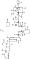
- a gas supply device 10 is provided in a hydrogen station as a hydrogen gas supply stand, for example, and supplies hydrogen to the dispenser 12 side in response to a filling command from a dispenser 12 that is a filling facility.
- Supply gas That is, the hydrogen station includes a gas supply device 10 and a dispenser 12 connected to the outflow end of the gas supply device 10.
- the dispenser 12 fills a tank provided in the vehicle 14 (tank mounting device) with hydrogen gas.
- the vehicle 14 is a fuel cell vehicle, for example.
- the gas supply device 10 includes a first compressor 22, a second compressor 24, a storage tank 26, a pressure accumulator 30, a gas flow path 16, and a controller 58 (control device).
- the gas flow passage 16 includes a main flow path 161 and a short circuit 162.
- the main channel 161 connects the gas supply source 20, the second compressor 24, the first compressor 22, the pressure accumulator 30 and the dispenser 12.
- the short circuit 162 connects the first compressor 22 and the dispenser 12 without going through the pressure accumulator 30.
- An inflow end 16a to which the gas supply source 20 can be connected is provided at the upstream end of the main flow path 161, and an outflow end 16b to which the dispenser 12 can be connected is provided at the downstream end.
- the first compressor 22 is constituted by a reciprocating compressor that reciprocates a piston by rotating a crankshaft (not shown) by driving a motor (not shown).
- a discharge valve (not shown) is opened and hydrogen gas is discharged.
- the 1st compressor 22 is not restricted to a reciprocating compressor, You may be comprised by the compressor of another type.
- the second compressor 24 is disposed on the upstream side of the first compressor 22 in the main flow path 161.
- a small compressor having a smaller compression capacity than the first compressor 22 may be used.
- the storage tank 26 is connected to the gas flow path 16 through a connection path 28 connected to a portion of the main flow path 161 between the second compressor 24 and the first compressor 22.
- the low-pressure hydrogen gas from the gas supply source 20 is compressed by the second compressor 24, and the gas discharged from the second compressor 24 is stored in the storage tank 26. Hydrogen gas in the storage tank 26 is sucked into the first compressor 22.
- various valves (not shown) are provided between the storage tank 26 and the first compressor 22, and between the storage tank 26 and the second compressor 24. The introduction of hydrogen gas and the derivation of hydrogen gas from the storage tank 26 are controlled.
- a pressure accumulator 30 is provided in a portion between the first compressor 22 and the outflow end 16b in the main flow path 161.
- the pressure accumulator 30 is for temporarily storing hydrogen gas, and stores the hydrogen gas compressed by the first compressor 22.
- the accumulator 30 is replenished with hydrogen gas by the first compressor 22 in advance, and the pressure is a set pressure (for example, 82 MPa).
- the number of the pressure accumulators 30 is 1, but may be 2 or more.
- the introduction line 18 a is provided with a check valve 33, an introduction side valve 34 that is an introduction side valve member, and a first on-off valve 41.
- the introduction side valve 34 is configured by an air-driven valve that only switches the opening degree.
- the check valve 33 allows only a flow toward the pressure accumulator 30 and blocks a flow in a direction flowing out from the pressure accumulator 30.
- the introduction side valve 34 may be other than the air drive valve.
- the first on-off valve 41 is disposed between the first compressor 22 and the check valve 33 and the introduction side valve 34.
- the lead-out line 18b is provided with a check valve 37, a lead-out side valve 38 which is a lead-out side valve member, and a second on-off valve 42.
- the derivation side valve 38 is constituted by an air driven valve.
- the check valve 37 allows only the flow in the direction of flowing out from the pressure accumulator 30 and blocks the flow toward the pressure accumulator 30.
- the second on-off valve 42 is disposed between the dispenser 12 and the check valve 37 and the outlet side valve 38.
- the short-circuit path 162 of the gas flow path 16 includes a portion between the first opening / closing valve 41 and the check valve 33 and the introduction side valve 34 in the introduction line 18a, and a second opening / closing valve 42 and the check valve in the outlet line 18b.
- the part between 37 and the outlet side valve 38 is short-circuited.
- a return flow path 45 is connected to the gas flow path 16.
- One end of the return passage 45 is connected to a portion between the discharge portion of the first compressor 22 and the first on-off valve 41, and the other end of the suction passage of the first compressor 22 and the connection passage 28. It is connected to the part between the connection points.
- a return valve 46 is provided in the return channel 45. When the return valve 46 is opened, part or all of the hydrogen gas discharged from the first compressor 22 is returned to the upstream side of the first compressor 22.
- the gas supply device 10 includes a first pressure sensor 48 that is a pressure detection unit.
- the first pressure sensor 48 is disposed in the short circuit 162.
- the pressure of the hydrogen gas measured by the first pressure sensor 48 corresponds to the pressure in the accumulator 30.
- the controller 58 controls the driving of the first compressor 22 and the second compressor 24 and controls the opening and closing of the first on-off valve 41, the second on-off valve 42, the introduction side valve 34, the outlet side valve 38, and the return valve 46. I do.
- the dispenser 12 includes an adapter 51, a supply path 52 that connects the adapter 51 and the outflow end 16 b of the gas flow path 16, a flow control valve 53 provided in the supply path 52, and a second pressure sensor that is a pressure detection unit. 54 is provided.
- the adapter 51 is attached to the gas supply port of the vehicle 14 when hydrogen gas is supplied.
- the flow control valve 53 is configured by an air driven valve. Note that a flow control valve other than the air drive valve may be used.
- the dispenser 12 is provided with a controller (not shown), and the controller controls the opening degree of the flow control valve 53 based on the detection value of the second pressure sensor 54. In the following description, when the downstream area and the vehicle 14 are collectively described with respect to the flow rate control valve 53 of the dispenser 12, they are referred to as “demand section”.
- the first compressor 22 and the pressure accumulator 30 are connected in series in the main flow path 161.
- the introduction side valve 34 and the outlet side valve 38 are opened, the gas supply device 10 is in a state where hydrogen gas can be introduced from the first compressor 22 into the pressure accumulator 30 via the introduction line 18a, and the pressure accumulation The hydrogen gas can be led out from the container 30 to the dispenser 12 through the lead-out line 18b.
- the operation mode of the gas supply device 10 that enables both the introduction of the hydrogen gas into the pressure accumulator 30 and the derivation of the hydrogen gas from the pressure accumulator 30 is referred to as a “series differential pressure filling operation”. That is, the controller 58 can execute an operation mode in which the introduction side valve 34 and the outlet side valve 38 are simultaneously opened, and the hydrogen gas is led out from the pressure accumulator 30 while the hydrogen gas is introduced into the pressure accumulator 30. It has become.
- the gas supply device 10 since the gas supply device 10 is connected to the dispenser 12 via the short circuit 162 (that is, not via the pressure accumulator 30), by closing the inlet side valve 34 and the outlet side valve 38, The total amount of hydrogen gas discharged from the first compressor 22 can be sent directly to the dispenser 12.
- the operation mode of the gas supply apparatus 10 that sends hydrogen gas from the first compressor 22 to the dispenser 12 without the pressure accumulator 30 is referred to as “direct charging operation”. That is, the controller 58 can execute an operation mode in which the first compressor 22 is driven with the introduction side valve 34 and the outlet side valve 38 closed at the same time.
- the gas supply device 10 can also perform an operation of supplying hydrogen gas from the pressure accumulator 30 to the dispenser 12 in a state where the supply of hydrogen gas from the first compressor 22 to the pressure accumulator 30 is stopped.
- this operation mode is referred to as “differential pressure filling operation” in distinction from the above-described series differential pressure filling operation. That is, the controller 58 can execute the operation mode in which the introduction side valve 34 is closed and the derivation side valve 38 is opened.
- the controller 58 of the gas supply device 10 can switch between a series differential pressure filling operation, a direct filling operation, and a differential pressure filling operation.
- FIG. 3 is a diagram illustrating the relationship between hydrogen gas pressure and time in the demand section.
- the straight lines 92 and 93 indicated by the solid lines illustrate the temporal transition of the hydrogen gas pressure in the demand section, and the straight line 91 indicated by the broken lines indicates the temporal transition of the hydrogen gas target pressure.
- the starting time for filling the vehicle 14 with hydrogen is used as the origin.
- the same slopes of the straight lines 91 to 93 are shown as being shifted up and down.
- the pressure of the hydrogen gas in the demand section is controlled to increase according to the target pressure indicated by the straight line 91 in FIG. 3, and the tank of the vehicle 14 has a final pressure Pt (for example, 3 minutes) at a predetermined time ts (for example, 3 minutes). 70 MPa).
- the gas supply method which supplies hydrogen gas to the dispenser 12 is implemented by the gas supply apparatus 10 operating as follows. Note that the operation of storing the hydrogen gas in the storage tank 26 by the second compressor 24 is intermittently performed based on the pressure of the hydrogen gas in the storage tank 26. In the following description, the operation of the equipment downstream of the second compressor 24 and the storage tank 26 of the gas supply device 10 will be noted and described.
- Gas supply to the dispenser 12 is started when a gas supply command is issued from the dispenser 12 to the gas supply device 10.
- the controller 58 first activates the first compressor 22.
- the controller 58 closes the first on-off valve 41 and returns the return valve 46 until the first compressor 22 is in a standby state, that is, until the hydrogen gas can be delivered to the introduction line 18a of the gas flow passage 16. Is released.
- the hydrogen gas circulates between the first compressor 22 and the return channel 45 without being substantially compressed by the first compressor 22.
- the controller 58 of the gas supply device 10 opens the outlet side valve 38 and the second on-off valve 42 to perform the differential pressure filling operation (step ST11).
- the introduction side valve 34 is closed.
- the opening degree of the flow control valve 53 is controlled so that the detection result of the second pressure sensor 54 becomes the target pressure. Therefore, as shown by a straight line 92 in FIG.
- the controller 58 opens the first on-off valve 41 and the introduction side valve 34 of the introduction line 18a, and closes the return valve 46. Thereby, the operation of the gas supply device 10 shifts to the series differential pressure filling operation (step ST12).
- the first compressor 22 delivers hydrogen gas to the introduction line 18 a of the gas flow passage 16.
- the return valve 46 does not need to be completely closed, and the flow rate of the hydrogen gas delivered from the first compressor 22 may be adjusted by adjusting the opening degree.
- the series differential pressure In the filling operation hydrogen gas is supplied to the dispenser 12 due to a pressure difference between the system and the demand unit. Further, the flow rate of the hydrogen gas is controlled by the flow rate control valve 53, whereby the hydrogen gas pressure in the demand section (see the straight line 92 in FIG. 3) gradually increases according to the target pressure.
- the controller 58 is configured so that the pressure of the hydrogen gas in the downstream portion 161a and the accumulator 30 becomes a set pressure (for example, 82 MPa) based on the detection value of the first pressure sensor 48.
- the number of rotations of 22 is controlled.
- Data obtained by processing the detection value of the first pressure sensor 48 may be used for controlling the rotational speed of the first compressor 22.
- the flow rate of hydrogen gas required from the dispenser 12 exceeds the upper limit of the flow rate that can be delivered from the first compressor 22 (hereinafter referred to as “upper limit amount”). Therefore, the difference between the required amount and the upper limit amount is derived from the pressure accumulator 30 to the dispenser 12, and the pressure in the pressure accumulator 30 and the downstream portion 161a decreases.
- the pressure of the hydrogen gas in the accumulator 30 in other words, the amount of hydrogen gas
- the pressure of the hydrogen gas in the accumulator 30 increases to the relationship between the flow rate of the hydrogen gas delivered from the first compressor 22 and the required amount required by the dispenser 12. Increase or decrease.
- step ST13 when the difference ⁇ P (that is, the pressure difference) between the detection value P1 of the first pressure sensor 48 and the detection value P2 of the second pressure sensor 54 becomes equal to or less than the set value A (step ST13), the controller 58 The introduction side valve 34 is closed while the first on-off valve 41 and the second on-off valve 42 are open, and the flow of hydrogen gas into the pressure accumulator 30 is shut off. Thereby, the operation of the gas supply device 10 shifts directly to the filling operation (step ST14). As a result, the entire amount of hydrogen gas is delivered from the first compressor 22 to the dispenser 12 via the short circuit 162. The controller 58 controls the rotation speed of the first compressor 22 so that the detection value of the second pressure sensor 54 becomes the target pressure. Therefore, the pressure of hydrogen gas in the demand section increases according to the target pressure. Note that the data obtained by processing the detection value of the second pressure sensor 54 may be compared with the target pressure, and the rotation speed control of the first compressor 22 may be performed.
- the 1st compressor 22 is connected to the pressure accumulator 30 in series in the main flow path 161.
- hydrogen gas can be introduced from the first compressor 22 to the pressure accumulator 30, and hydrogen gas can be led from the pressure accumulator 30 to the dispenser 12.
- the fall of the pressure in the pressure accumulator 30 during the drive of the gas supply apparatus 10 can be suppressed compared with the gas supply apparatus which performs only differential pressure filling operation.
- the recovery time of the pressure accumulator 30 can be shortened, and the filling of hydrogen gas into the next vehicle 14 can be started quickly.
- the rotation speed of the first compressor 22 is controlled so that the pressure of the hydrogen gas in the downstream portion 161a is maintained at the set pressure based on the detection result of the first pressure sensor 48. For this reason, the fall of the pressure of the hydrogen gas in the downstream part 161a and the pressure accumulator 30 is suppressed more. Furthermore, the pressure of the hydrogen gas by the flow rate control valve 53 (or the flow rate) is facilitated by maintaining the pressures of the downstream portion 161a and the pressure accumulator 30 positioned on the upstream side of the dispenser 12 constant.
- hydrogen gas is sent from the pressure accumulator 30 to the dispenser 12 before the first compressor 22 enters a standby state. Thereby, the hydrogen gas can be quickly filled into the vehicle 14 carried into the hydrogen station.
- the short circuit 162 in the gas flow passage 16 it is possible to easily switch from the series differential pressure filling operation to the direct filling operation.
- the direct charging operation since the rotation speed of the first compressor 22 is controlled based on the detection result of the second pressure sensor 54, the hydrogen gas pressure in the demand section can be increased according to the target pressure.
- the hydrogen gas from the gas supply source 20 is compressed using the second compressor 24, which is a compressor other than the first compressor 22, and the compressed hydrogen gas is stored in the storage tank 26. Is done.
- the compression ratio that is, the pressure ratio between the suction side and the discharge side
- the first compressor 22 can be reduced in size.
- the controller 58 may close the introduction side valve 34 and block the flow of hydrogen gas from the first compressor 22 to the pressure accumulator 30.
- the introduction side valve 34 may be opened and closed based on various calculations. .
- the controller 58 may close the introduction side valve 34 and block the flow of hydrogen gas from the first compressor 22 to the pressure accumulator 30. Further, the controller 58 may open and close the introduction side valve 34 based on whether or not the difference between the target pressure Pm and the detected value P1 has become a set value. The controller 58 may open and close the introduction side valve 34 based on the ratio of the detected value P1 to the target pressure Pm. As described above, if the shift to the direct charging operation is performed based on the change in the detected value of the second pressure sensor 54 with respect to the target pressure Pm, the introduction side valve 34 may be opened and closed based on various calculations.
- the short circuit 162 may be omitted.
- the introduction side valve 34 and the outlet side valve 38 are opened, so that hydrogen gas is introduced into the pressure accumulator 30. And hydrogen gas can be led out from the pressure accumulator 30 to the dispenser 12. As a result, a decrease in pressure in the pressure accumulator 30 during operation of the gas supply device 10 can be suppressed.
- the differential pressure filling operation is not necessarily performed.
- the first pressure sensor 48 may be disposed in the downstream portion 161a of the main flow path 161, more specifically, between the first compressor 22 and the first on-off valve 41. In this case, the pressure corresponding to the pressure of the pressure accumulator 30 is measured by the first pressure sensor 48. Further, the first pressure sensor 48 may be directly attached to the accumulator 30. In this case, the first pressure sensor 48 is configured to detect the pressure in the pressure accumulator 30.
- the introduction line 18 a and the lead-out line 18 b may be configured by a single pipe 18.
- the pipe 18 is provided with a valve member 39 such as an on-off valve.
- the second compressor 24 and the storage tank 26 are provided. However, these are omitted, and hydrogen gas is sent directly from the gas supply source 20 to the first compressor 22. Good.
- the gas supply device 10 may be used for filling hydrogen gas into a tank mounting device other than the vehicle.
- the gas supply device may be used for supplying a gas other than hydrogen gas.
- the compressor is connected in series with the accumulator, so that gas can be introduced into the accumulator and gas can be led out from the accumulator to the filling facility.
- the compressor supplies gas, it is possible to suppress a decrease in pressure in the pressure accumulator during operation of the gas supply device. As a result, the recovery time of the pressure accumulator can be shortened, and the filling of gas into the next tank mounting device can be started promptly.
- the gas supply device may include a pressure detector that detects a pressure in the pressure accumulator or a pressure corresponding thereto.
- the controller rotates the compressor so that the gas pressure is maintained at a predetermined pressure based on the detection result of the pressure detection unit when the compressor sends the gas to the gas flow passage. The number may be controlled.
- the pressure drop in the accumulator can be further suppressed. As a result, supply control of gas from the filling facility to the vehicle becomes easier.
- the gas flow path includes the introduction line and the outlet line, and the main flow path connecting the compressor, the pressure accumulator, and the filling equipment, and the filling from the compressor without passing through the pressure accumulator.
- You may provide the short circuit which short-circuits the said introductory line and the said derivation
- the filling facility may be provided with another pressure detection unit.
- the control device closes the introduction-side valve based on a pressure change between the pressure detection unit and the other pressure detection unit, and based on a detection result of the other pressure detection unit, the compressor The number of rotations may be controlled.
- the gas flow path includes the introduction line and the lead-out line, the main flow path connecting the compressor, the accumulator and the filling equipment, and the filling from the compressor without passing through the accumulator
- the filling facility may be provided with another pressure detection unit.
- the control device closes the introduction-side valve based on a change in the detection value of the other pressure detection unit with respect to the target pressure of the gas in the filling facility, and based on the detection result of the other pressure detection unit. You may control the rotation speed of the said compressor.
- the control device may be configured to be able to close the introduction side valve and open the derivation side valve.
- the gas can be supplied to the filling facility by the differential pressure filling operation.
- the gas supply device may further include another compressor that compresses the gas of the gas supply source, and a storage tank that stores the gas discharged from the other compressor.
- the compressor may suck the gas in the storage tank.
- gas discharged from another compressor is stored in a storage tank, and the stored gas is compressed in the compressor.
- the compression ratio in a compressor can be suppressed. Therefore, the compressor can be reduced in size.
- the embodiment includes the gas supply device and a filling facility connected to an outflow end of the gas supply device, and the tank is installed with the hydrogen gas supplied from the gas supply device by the filling facility. It is a hydrogen station that fills the equipment.
- the embodiment is a gas supply method using a gas supply device, and the gas supply device is disposed downstream of the compressor that compresses the gas and fills the tank mounting device with the gas.
- the compressor is connected in series with the pressure accumulator, so that the gas can be introduced into the accumulator and the gas can be led out from the accumulator to the filling facility.
- the compressor supplies gas, it is possible to suppress a decrease in pressure in the pressure accumulator during operation of the gas supply device. As a result, the recovery time of the pressure accumulator can be shortened, and the filling of gas into the next tank mounting device can be started promptly.
- the gas flow passage may include a pressure detection unit disposed downstream of the compressor.
- the gas pressure is maintained at a predetermined pressure based on the detection result of the pressure detection unit.
- the rotational speed may be controlled.
- the pressure drop in the accumulator can be further suppressed. As a result, supply control of gas from the filling facility to the vehicle becomes easier.
- the gas supply method cuts off a gas flow from the compressor to the accumulator based on a pressure change between the pressure detection unit and another pressure detection unit provided in the filling facility. May be. Moreover, while controlling the rotation speed of the said compressor based on the detection result of the said other pressure detection part, you may send gas from the said compressor to the said filling equipment, without passing through the said accumulator.
- the number of revolutions of the compressor may be controlled based on the detection result of the other pressure detector, and gas may be sent from the compressor to the filling facility without passing through the accumulator.
- gas may be sent from the pressure accumulator to the filling facility before the compressor is ready to send gas to the introduction line.
- gas can be supplied promptly to the filling facility.
- the gas supply method further comprising: another compressor that compresses the gas of the gas supply source; and a storage tank that stores the gas discharged from the other compressor.
- the gas in the storage tank may be sucked.
Abstract
Description
Claims (13)
- ガスを圧縮する圧縮機と、
前記圧縮機の下流に配置され、タンク搭載装置へガスを充填する充填設備へガスを供給する蓄圧器と、
前記圧縮機、前記蓄圧器及び前記充填設備を繋ぐガス流通路と、
を備え、
前記ガス流通路が、
前記圧縮機から前記蓄圧器へガスを導入する導入ラインと、
前記蓄圧器から前記充填設備へガスを導出する導出ラインと、
前記導入ラインに設けられた導入側弁と、
前記導出ラインに設けられた導出側弁と、
を備え、
ガス供給装置は、前記導入側弁及び前記導出側弁の開閉を制御する制御装置をさらに備え、
前記制御装置は、前記導入側弁と前記導出側弁とが同時に開である状態にすることを可能に構成されている、ガス供給装置。 - 前記蓄圧器内の圧力またはこれに相当する圧力を検出する圧力検出部を備え、
前記制御装置は、前記圧縮機が前記ガス流通路へガスを送出する際に、前記圧力検出部の検出結果に基づきガスの圧力が所定圧力に維持されるように前記圧縮機の回転数を制御する、請求項1に記載のガス供給装置。 - 前記ガス流通路が、
前記導入ライン及び前記導出ラインを含み、前記圧縮機、前記蓄圧器及び前記充填設備を繋ぐメイン流路と、
前記蓄圧器を通らずに前記圧縮機から前記充填設備へとガスを送ることが可能となるように、前記導入ラインと前記導出ラインとを短絡する短絡路と、
を備え、
前記充填設備には他の圧力検出部が設けられ、
前記制御装置は、
前記圧力検出部と前記他の圧力検出部との間の圧力変化に基づいて前記導入側弁を閉じるとともに、
前記他の圧力検出部の検出結果に基づき前記圧縮機の回転数を制御する、請求項2に記載のガス供給装置。 - 前記ガス流通路が、
前記導入ライン及び前記導出ラインを含み、前記圧縮機、前記蓄圧器及び前記充填設備を繋ぐメイン流路と、
前記蓄圧器を通らずに前記圧縮機から前記充填設備へとガスを送ることが可能となるように、前記導入ラインと前記導出ラインとを短絡する短絡路と、
を備え、
前記充填設備には他の圧力検出部が設けられ、
前記制御装置は、
前記充填設備におけるガスの目標圧力に対する前記他の圧力検出部の検出値の変化に基づいて前記導入側弁を閉じるとともに、
前記他の圧力検出部の検出結果に基づき前記圧縮機の回転数を制御する、請求項2に記載のガス供給装置。 - 前記制御装置は、前記導入側弁を閉状態とするとともに、前記導出側弁を開状態にすることを可能に構成されている、請求項1に記載のガス供給装置。
- ガス供給源のガスを圧縮する他の圧縮機と、
前記他の圧縮機から吐出されたガスを貯留する貯留タンクと、
をさらに備え、
前記圧縮機が、前記貯留タンクのガスを吸入する請求項1に記載のガス供給装置。 - 請求項1ないし6の何れか1項に記載のガス供給装置と、
前記ガス供給装置の流出端に接続された充填設備と、を備え、
前記充填設備が前記ガス供給装置から供給された水素ガスを前記タンク搭載装置に充填する水素ステーション。 - ガス供給装置によるガス供給方法であって、
前記ガス供給装置が、
ガスを圧縮する圧縮機と、
前記圧縮機の下流に配置され、タンク搭載装置へガスを充填する充填設備へガスを供給する蓄圧器と、
前記圧縮機、前記蓄圧器及び前記充填設備を繋ぐガス流通路と、
を備え、
前記圧縮機から前記蓄圧器にガスを導入すると同時に、前記蓄圧器から前記充填設備にガスを導出する工程を含む、ガス供給方法。 - 前記ガス流通路が前記圧縮機よりも下流に配置される圧力検出部を備え、
前記圧縮機が前記ガス流通路へガスを送出する際に、前記圧力検出部の検出結果に基づきガスの圧力が所定圧力に維持されるように前記圧縮機の回転数を制御する、請求項8に記載のガス供給方法。 - 前記圧力検出部と前記充填設備に設けられた他の圧力検出部との間の圧力変化に基づいて前記圧縮機から前記蓄圧器へのガスの流れを遮断し、
前記他の圧力検出部の検出結果に基づき前記圧縮機の回転数を制御するとともに、前記蓄圧器を介することなく前記圧縮機から前記充填設備へとガスを送る、請求項9に記載のガス供給方法。 - 前記充填設備におけるガスの目標圧力に対する前記充填設備に設けられた他の圧力検出部の検出値の変化に基づいて前記圧縮機から前記蓄圧器へのガスの流れを遮断し、
前記他の圧力検出部の検出結果に基づき前記圧縮機の回転数を制御するとともに、前記蓄圧器を介することなく前記圧縮機から前記充填設備へとガスを送る、請求項9に記載のガス供給方法。 - 前記圧縮機が前記導入ラインにガスを送出可能な状態となる前に、前記蓄圧器から前記充填設備へガスの送出を行う、請求項8に記載のガス供給方法。
- ガス供給源のガスを圧縮する他の圧縮機と、
前記他の圧縮機から吐出されたガスを貯留する貯留タンクと、
をさらに備え、
前記圧縮機が、前記貯留タンクのガスを吸入する、請求項8に記載のガス供給方法。
Priority Applications (7)
| Application Number | Priority Date | Filing Date | Title |
|---|---|---|---|
| CN201580008520.XA CN106030187B (zh) | 2014-02-14 | 2015-01-21 | 气体供给装置、加氢站以及气体供给方法 |
| KR1020167025000A KR101883584B1 (ko) | 2014-02-14 | 2015-01-21 | 가스 공급 장치, 수소 스테이션 및 가스 공급 방법 |
| BR112016018751A BR112016018751A2 (pt) | 2014-02-14 | 2015-01-21 | dispositivo de fornecimento de gás, estação de hidrogênio, e método de fornecimento de gás. |
| US15/118,577 US10563820B2 (en) | 2014-02-14 | 2015-01-21 | Gas supply device, hydrogen station, and gas supply method |
| CA2938391A CA2938391C (en) | 2014-02-14 | 2015-01-21 | Gas supply device, hydrogen station, and gas supply method |
| EP15749478.2A EP3106739B1 (en) | 2014-02-14 | 2015-01-21 | Gas supply device, hydrogen station, and gas supply method |
| US15/959,871 US10883662B2 (en) | 2014-02-14 | 2018-04-23 | Gas supply device, hydrogen station, and gas supply method |
Applications Claiming Priority (2)
| Application Number | Priority Date | Filing Date | Title |
|---|---|---|---|
| JP2014-026433 | 2014-02-14 | ||
| JP2014026433A JP6279340B2 (ja) | 2014-02-14 | 2014-02-14 | ガス供給装置、水素ステーション及びガス供給方法 |
Related Child Applications (2)
| Application Number | Title | Priority Date | Filing Date |
|---|---|---|---|
| US15/118,577 A-371-Of-International US10563820B2 (en) | 2014-02-14 | 2015-01-21 | Gas supply device, hydrogen station, and gas supply method |
| US15/959,871 Division US10883662B2 (en) | 2014-02-14 | 2018-04-23 | Gas supply device, hydrogen station, and gas supply method |
Publications (1)
| Publication Number | Publication Date |
|---|---|
| WO2015122247A1 true WO2015122247A1 (ja) | 2015-08-20 |
Family
ID=53799995
Family Applications (1)
| Application Number | Title | Priority Date | Filing Date |
|---|---|---|---|
| PCT/JP2015/051470 WO2015122247A1 (ja) | 2014-02-14 | 2015-01-21 | ガス供給装置、水素ステーション及びガス供給方法 |
Country Status (8)
| Country | Link |
|---|---|
| US (2) | US10563820B2 (ja) |
| EP (1) | EP3106739B1 (ja) |
| JP (1) | JP6279340B2 (ja) |
| KR (1) | KR101883584B1 (ja) |
| CN (1) | CN106030187B (ja) |
| BR (1) | BR112016018751A2 (ja) |
| CA (1) | CA2938391C (ja) |
| WO (1) | WO2015122247A1 (ja) |
Cited By (1)
| Publication number | Priority date | Publication date | Assignee | Title |
|---|---|---|---|---|
| EP3270033A1 (de) * | 2016-07-13 | 2018-01-17 | Franz Braun | Verfahren zum betanken von insbesondere lastkraftfahrzeugen mit erdgas |
Families Citing this family (27)
| Publication number | Priority date | Publication date | Assignee | Title |
|---|---|---|---|---|
| JP6276120B2 (ja) * | 2014-06-27 | 2018-02-07 | 株式会社神戸製鋼所 | ガス圧縮装置 |
| JP2017075656A (ja) * | 2015-10-15 | 2017-04-20 | 株式会社日立プラントメカニクス | 水素吸蔵合金を用いた貯槽システム |
| KR102173489B1 (ko) * | 2016-02-23 | 2020-11-03 | 토키코 시스템 솔루션즈 가부시키가이샤 | 고압 수소의 팽창 터빈·컴프레서식 충전 시스템 및 그 제어 방법 |
| JP6618842B2 (ja) * | 2016-03-17 | 2019-12-11 | 東京瓦斯株式会社 | 水素ステーション |
| JP2018084329A (ja) * | 2016-11-11 | 2018-05-31 | Jxtgエネルギー株式会社 | 水素燃料の供給方法及び水素供給システム |
| DK3551926T3 (da) * | 2016-12-06 | 2020-11-16 | Air Liquide | Hydrogenoptankningssystem |
| JP7179763B2 (ja) * | 2017-01-17 | 2022-11-29 | アイヴィーズ インコーポレイテッド | 水素ガス分配システム及びその方法 |
| KR102122874B1 (ko) * | 2017-07-28 | 2020-06-15 | 가부시키가이샤 고베 세이코쇼 | 가연성 가스 공급 유닛 및 수소 스테이션 |
| WO2019026126A1 (en) * | 2017-07-31 | 2019-02-07 | Air Liquide Japan Ltd. | HYDROGEN SUPPLY SYSTEM AND HYDROGEN REFUELING METHOD |
| KR102241817B1 (ko) * | 2017-09-08 | 2021-04-16 | 한국조선해양 주식회사 | 가스 처리 시스템 및 이를 포함하는 선박 |
| DK179886B1 (en) | 2018-03-07 | 2019-08-27 | Nel Hydrogen A/S | A HYDROGEN REFUELING STATION AND A METHOD FOR CONTROLLING THE HYDROGEN REFUELING STATION |
| FR3079006B1 (fr) * | 2018-03-14 | 2021-05-28 | Air Liquide | Station de remplissage de reservoir(s) de gaz sous pression et procede d'augmentation de son autonomie |
| CN110939860B (zh) * | 2018-09-21 | 2021-03-16 | 国家能源投资集团有限责任公司 | 加氢站控制系统、方法以及加氢站 |
| FR3086993B1 (fr) * | 2018-10-09 | 2021-11-26 | Air Liquide | Procede et installation de stockage et de distribution d'hydrogene liquefie |
| JP7187251B2 (ja) * | 2018-10-18 | 2022-12-12 | 岩谷産業株式会社 | 車載容器への水素ガス充填方法及び水素ステーション |
| EP3884203A1 (en) | 2018-11-20 | 2021-09-29 | Nel Hydrogen A/S | High volume, fast hydrogen fueling of a heavy-duty vehicle |
| JP7185277B2 (ja) * | 2018-12-25 | 2022-12-07 | サムテック株式会社 | 水素ステーション、及びその水素ステーションの運転方法 |
| FR3098274B1 (fr) * | 2019-07-03 | 2022-01-28 | Air Liquide | Dispositif et procédé de remplissage de réservoirs. |
| EP4008684A1 (en) * | 2019-08-01 | 2022-06-08 | Tatsumi Ryoki Co., Ltd | Load testing device |
| JP7043031B2 (ja) * | 2020-03-03 | 2022-03-29 | 株式会社タツノ | 充填装置 |
| NZ797055A (en) * | 2020-07-13 | 2023-05-26 | Zero Emission Ind Inc | Gaseous fueling system |
| CN115247755A (zh) * | 2021-04-26 | 2022-10-28 | 阜新德尔汽车部件股份有限公司 | 加氢装置以及方法、系统 |
| US20220364679A1 (en) * | 2021-05-17 | 2022-11-17 | Estis Compression, LLC | Methane Retention System |
| CN113623170B (zh) * | 2021-08-13 | 2022-12-27 | 上海氢枫能源技术有限公司 | 压缩机氢气循环方法及系统 |
| US20230137335A1 (en) * | 2021-10-29 | 2023-05-04 | Air Products And Chemicals, Inc. | Hydrogen storage and dispensing apparatus and method |
| JP7141565B1 (ja) | 2022-05-26 | 2022-09-22 | 東京瓦斯株式会社 | 水素ステーション |
| CN116498889B (zh) * | 2023-06-05 | 2023-11-10 | 天津新氢能源发展有限公司 | 氢气充装系统及方法 |
Citations (9)
| Publication number | Priority date | Publication date | Assignee | Title |
|---|---|---|---|---|
| US5385176A (en) * | 1993-07-19 | 1995-01-31 | Price Compressor Company, Inc. | Natural gas dispensing |
| JPH08100888A (ja) * | 1994-09-30 | 1996-04-16 | Tokyo Gas Co Ltd | ガス供給装置 |
| JPH08109999A (ja) * | 1994-10-08 | 1996-04-30 | Kachi Tec:Kk | ボンベへの圧縮燃料ガス充填方法及び装置 |
| JP2003172497A (ja) * | 2001-12-05 | 2003-06-20 | Koatsu Gas Kogyo Co Ltd | 自動車用天然ガス充填設備 |
| JP2011074925A (ja) * | 2009-09-29 | 2011-04-14 | Taiyo Nippon Sanso Corp | 水素ガスの充填方法及び充填装置 |
| JP2013015155A (ja) * | 2011-06-30 | 2013-01-24 | Kobe Steel Ltd | 水素ステーション |
| JP2013130278A (ja) * | 2011-12-22 | 2013-07-04 | Tokiko Techno Kk | ガス供給装置 |
| JP2013130218A (ja) * | 2011-12-20 | 2013-07-04 | Kobe Steel Ltd | ガス供給方法およびガス供給装置 |
| WO2014084243A1 (ja) * | 2012-11-27 | 2014-06-05 | Jx日鉱日石エネルギー株式会社 | 水素ステーション及び水素ステーションにおける蓄圧器への水素充填方法 |
Family Cites Families (13)
| Publication number | Priority date | Publication date | Assignee | Title |
|---|---|---|---|---|
| US4527600A (en) * | 1982-05-05 | 1985-07-09 | Rockwell International Corporation | Compressed natural gas dispensing system |
| DE19650999C1 (de) * | 1996-11-26 | 1998-06-04 | Mannesmann Ag | Verfahren zur Befüllung eines mobilen Gastanks und Zapfanlage |
| US7287558B2 (en) * | 2003-07-03 | 2007-10-30 | Arizona Public Service Company | Hydrogen handling or dispensing system |
| US7892304B2 (en) * | 2004-12-17 | 2011-02-22 | Texaco Inc. | Apparatus and method for controlling compressor motor speed in a hydrogen generator |
| FR2891347B1 (fr) * | 2005-09-28 | 2007-11-02 | Air Liquide | Procede et dispositif de remplissage d'un gaz sous pression dans un reservoir |
| JP5357060B2 (ja) * | 2007-03-02 | 2013-12-04 | エナシー トランスポート エルエルシー | 圧縮流体の格納容器への流し込み及び流し出しのための装置及び方法 |
| US7987877B2 (en) * | 2007-12-14 | 2011-08-02 | Texaco Inc. | Method for managing storage of gaseous hydrogen |
| KR101588173B1 (ko) * | 2011-04-26 | 2016-01-25 | 가부시키가이샤 고베 세이코쇼 | 수소 스테이션 |
| US8899278B2 (en) * | 2011-06-17 | 2014-12-02 | Air Products And Chemicals, Inc. | Pressure cycle management in compressed gas dispensing systems |
| JP5355639B2 (ja) * | 2011-08-16 | 2013-11-27 | 東京瓦斯株式会社 | 水素ステーション |
| US9765930B2 (en) * | 2012-01-31 | 2017-09-19 | J-W Power Company | CNG fueling system |
| US9434598B2 (en) | 2012-03-15 | 2016-09-06 | Ultimate Cng, Llc | Mobile fueling vehicle and method |
| US9360161B2 (en) * | 2013-01-22 | 2016-06-07 | R. Keith Barker | Compressed natural gas storage and dispensing system |
-
2014
- 2014-02-14 JP JP2014026433A patent/JP6279340B2/ja active Active
-
2015
- 2015-01-21 CN CN201580008520.XA patent/CN106030187B/zh active Active
- 2015-01-21 WO PCT/JP2015/051470 patent/WO2015122247A1/ja active Application Filing
- 2015-01-21 US US15/118,577 patent/US10563820B2/en not_active Expired - Fee Related
- 2015-01-21 KR KR1020167025000A patent/KR101883584B1/ko active IP Right Grant
- 2015-01-21 CA CA2938391A patent/CA2938391C/en active Active
- 2015-01-21 EP EP15749478.2A patent/EP3106739B1/en active Active
- 2015-01-21 BR BR112016018751A patent/BR112016018751A2/pt not_active Application Discontinuation
-
2018
- 2018-04-23 US US15/959,871 patent/US10883662B2/en active Active
Patent Citations (9)
| Publication number | Priority date | Publication date | Assignee | Title |
|---|---|---|---|---|
| US5385176A (en) * | 1993-07-19 | 1995-01-31 | Price Compressor Company, Inc. | Natural gas dispensing |
| JPH08100888A (ja) * | 1994-09-30 | 1996-04-16 | Tokyo Gas Co Ltd | ガス供給装置 |
| JPH08109999A (ja) * | 1994-10-08 | 1996-04-30 | Kachi Tec:Kk | ボンベへの圧縮燃料ガス充填方法及び装置 |
| JP2003172497A (ja) * | 2001-12-05 | 2003-06-20 | Koatsu Gas Kogyo Co Ltd | 自動車用天然ガス充填設備 |
| JP2011074925A (ja) * | 2009-09-29 | 2011-04-14 | Taiyo Nippon Sanso Corp | 水素ガスの充填方法及び充填装置 |
| JP2013015155A (ja) * | 2011-06-30 | 2013-01-24 | Kobe Steel Ltd | 水素ステーション |
| JP2013130218A (ja) * | 2011-12-20 | 2013-07-04 | Kobe Steel Ltd | ガス供給方法およびガス供給装置 |
| JP2013130278A (ja) * | 2011-12-22 | 2013-07-04 | Tokiko Techno Kk | ガス供給装置 |
| WO2014084243A1 (ja) * | 2012-11-27 | 2014-06-05 | Jx日鉱日石エネルギー株式会社 | 水素ステーション及び水素ステーションにおける蓄圧器への水素充填方法 |
Non-Patent Citations (1)
| Title |
|---|
| See also references of EP3106739A4 * |
Cited By (1)
| Publication number | Priority date | Publication date | Assignee | Title |
|---|---|---|---|---|
| EP3270033A1 (de) * | 2016-07-13 | 2018-01-17 | Franz Braun | Verfahren zum betanken von insbesondere lastkraftfahrzeugen mit erdgas |
Also Published As
| Publication number | Publication date |
|---|---|
| EP3106739B1 (en) | 2020-12-16 |
| EP3106739A4 (en) | 2017-10-18 |
| US20170051875A1 (en) | 2017-02-23 |
| JP6279340B2 (ja) | 2018-02-14 |
| BR112016018751A2 (pt) | 2017-09-26 |
| US20180238493A1 (en) | 2018-08-23 |
| CN106030187A (zh) | 2016-10-12 |
| CN106030187B (zh) | 2019-03-15 |
| US10883662B2 (en) | 2021-01-05 |
| EP3106739A1 (en) | 2016-12-21 |
| CA2938391A1 (en) | 2015-08-20 |
| KR101883584B1 (ko) | 2018-07-30 |
| JP2015152091A (ja) | 2015-08-24 |
| KR20160120319A (ko) | 2016-10-17 |
| US10563820B2 (en) | 2020-02-18 |
| CA2938391C (en) | 2019-04-23 |
Similar Documents
| Publication | Publication Date | Title |
|---|---|---|
| WO2015122247A1 (ja) | ガス供給装置、水素ステーション及びガス供給方法 | |
| KR101693083B1 (ko) | 가스 충전 장치 및 가스 충전 방법 | |
| WO2012147340A1 (ja) | 水素ステーション | |
| US20150153005A1 (en) | Gas filling apparatus and gas filling method | |
| KR101633568B1 (ko) | 가스 공급 방법 및 가스 공급 장치 | |
| JP5839545B2 (ja) | 水素ステーション | |
| JP2012047234A (ja) | ガス充填装置 | |
| CN102465867B (zh) | 压缩装置及其运转控制方法 | |
| JP6997648B2 (ja) | 圧縮機システム | |
| JP2011112213A (ja) | ガスステーション及びガス充填システム | |
| KR101452726B1 (ko) | 압축기 제어 시스템 | |
| JP4938304B2 (ja) | ポンプの制御方法及び給水装置 | |
| US11053944B2 (en) | Subsea barrier fluid system | |
| JP5325701B2 (ja) | 空気圧縮機の制御方法及び空気圧縮機 | |
| CN106255828A (zh) | 泵送系统中的泵送方法以及真空泵系统 | |
| JP2008169723A (ja) | 圧縮機の運転方法 | |
| JP6429085B2 (ja) | ガス供給装置 | |
| CN105484969A (zh) | 真空泵系统 | |
| JP2019183993A (ja) | ガス供給装置及びその停止制御方法 | |
| US11035520B1 (en) | Method for controlling compression system, compression system, and hydrogen station | |
| JP4549825B2 (ja) | オイルフリー圧縮機の速度制御方法 | |
| KR100956062B1 (ko) | 유체 충전 장치 |
Legal Events
| Date | Code | Title | Description |
|---|---|---|---|
| 121 | Ep: the epo has been informed by wipo that ep was designated in this application |
Ref document number: 15749478 Country of ref document: EP Kind code of ref document: A1 |
|
| ENP | Entry into the national phase |
Ref document number: 2938391 Country of ref document: CA |
|
| REEP | Request for entry into the european phase |
Ref document number: 2015749478 Country of ref document: EP |
|
| WWE | Wipo information: entry into national phase |
Ref document number: 2015749478 Country of ref document: EP |
|
| WWE | Wipo information: entry into national phase |
Ref document number: 15118577 Country of ref document: US |
|
| NENP | Non-entry into the national phase |
Ref country code: DE |
|
| ENP | Entry into the national phase |
Ref document number: 20167025000 Country of ref document: KR Kind code of ref document: A |
|
| REG | Reference to national code |
Ref country code: BR Ref legal event code: B01A Ref document number: 112016018751 Country of ref document: BR |
|
| ENP | Entry into the national phase |
Ref document number: 112016018751 Country of ref document: BR Kind code of ref document: A2 Effective date: 20160815 |