WO2015118937A1 - Composant de blindage électromagnétique et fil électrique avec le composant de blindage électromagnétique - Google Patents
Composant de blindage électromagnétique et fil électrique avec le composant de blindage électromagnétique Download PDFInfo
- Publication number
- WO2015118937A1 WO2015118937A1 PCT/JP2015/051350 JP2015051350W WO2015118937A1 WO 2015118937 A1 WO2015118937 A1 WO 2015118937A1 JP 2015051350 W JP2015051350 W JP 2015051350W WO 2015118937 A1 WO2015118937 A1 WO 2015118937A1
- Authority
- WO
- WIPO (PCT)
- Prior art keywords
- shield
- pipe
- peripheral surface
- electric wire
- electromagnetic shielding
- Prior art date
Links
Images

Classifications
-
- H—ELECTRICITY
- H05—ELECTRIC TECHNIQUES NOT OTHERWISE PROVIDED FOR
- H05K—PRINTED CIRCUITS; CASINGS OR CONSTRUCTIONAL DETAILS OF ELECTRIC APPARATUS; MANUFACTURE OF ASSEMBLAGES OF ELECTRICAL COMPONENTS
- H05K9/00—Screening of apparatus or components against electric or magnetic fields
- H05K9/0073—Shielding materials
- H05K9/0098—Shielding materials for shielding electrical cables
-
- H—ELECTRICITY
- H01—ELECTRIC ELEMENTS
- H01R—ELECTRICALLY-CONDUCTIVE CONNECTIONS; STRUCTURAL ASSOCIATIONS OF A PLURALITY OF MUTUALLY-INSULATED ELECTRICAL CONNECTING ELEMENTS; COUPLING DEVICES; CURRENT COLLECTORS
- H01R13/00—Details of coupling devices of the kinds covered by groups H01R12/70 or H01R24/00 - H01R33/00
- H01R13/648—Protective earth or shield arrangements on coupling devices, e.g. anti-static shielding
- H01R13/658—High frequency shielding arrangements, e.g. against EMI [Electro-Magnetic Interference] or EMP [Electro-Magnetic Pulse]
- H01R13/6591—Specific features or arrangements of connection of shield to conductive members
- H01R13/6592—Specific features or arrangements of connection of shield to conductive members the conductive member being a shielded cable
-
- H—ELECTRICITY
- H02—GENERATION; CONVERSION OR DISTRIBUTION OF ELECTRIC POWER
- H02G—INSTALLATION OF ELECTRIC CABLES OR LINES, OR OF COMBINED OPTICAL AND ELECTRIC CABLES OR LINES
- H02G3/00—Installations of electric cables or lines or protective tubing therefor in or on buildings, equivalent structures or vehicles
- H02G3/02—Details
- H02G3/04—Protective tubing or conduits, e.g. cable ladders or cable troughs
- H02G3/0462—Tubings, i.e. having a closed section
-
- H—ELECTRICITY
- H02—GENERATION; CONVERSION OR DISTRIBUTION OF ELECTRIC POWER
- H02G—INSTALLATION OF ELECTRIC CABLES OR LINES, OR OF COMBINED OPTICAL AND ELECTRIC CABLES OR LINES
- H02G3/00—Installations of electric cables or lines or protective tubing therefor in or on buildings, equivalent structures or vehicles
- H02G3/02—Details
- H02G3/06—Joints for connecting lengths of protective tubing or channels, to each other or to casings, e.g. to distribution boxes; Ensuring electrical continuity in the joint
-
- H—ELECTRICITY
- H05—ELECTRIC TECHNIQUES NOT OTHERWISE PROVIDED FOR
- H05K—PRINTED CIRCUITS; CASINGS OR CONSTRUCTIONAL DETAILS OF ELECTRIC APPARATUS; MANUFACTURE OF ASSEMBLAGES OF ELECTRICAL COMPONENTS
- H05K9/00—Screening of apparatus or components against electric or magnetic fields
- H05K9/0007—Casings
- H05K9/0018—Casings with provisions to reduce aperture leakages in walls, e.g. terminals, connectors, cables
Definitions
- the present invention relates to an electromagnetic shield component including a hard shield pipe and a flexible shield member, and an electric wire with an electromagnetic shield component including the same.
- an electromagnetic shielding part surrounding the wire may be employed.
- the electromagnetic shielding component has a hard metal pipe and a cylindrical braided wire connected thereto.
- the metal pipe performs an electromagnetic shielding function, physically protects the electric wire, and further maintains the electric wire in a shape along a predetermined wiring path.
- the braided wire is a member formed in a cylindrical shape by knitting copper wire, it has flexibility.
- the braided wire having flexibility fulfills an electromagnetic shielding function and enables bending deformation of a portion near the end of the electric wire.
- a metal pipe and a braided wire are usually connected by caulking.
- the metal pipe in the caulking, the metal pipe is fastened from the outer peripheral surface side, and a part of the braided wire covering the outer peripheral surface near the end of the metal pipe is sandwiched between the metal pipe. Thereby, the part near the end of the braided wire stays on the outer peripheral surface side of the part near the end of the metal pipe.
- the braided wire is sandwiched between the outer peripheral surface of the support member inserted into the metal pipe and the inner peripheral surface of the crimped portion (compressed portion) of the metal pipe. Thereby, the part near the end of the braided wire stays on the inner peripheral surface side of the part near the end of the metal pipe.
- the end face of the metal pipe exists inside the braided wire.
- the electric wire passed through the hollow portion of the metal pipe may be damaged by contact with the edge of the end surface of the metal pipe.
- a general electromagnetic shielding component is provided with an edge cover that covers the end of the metal pipe.
- an edge cover that covers the end of the metal pipe.
- the present invention relates to an electromagnetic shield component, and even if the housing density of the electric wire in the hollow portion of the hard pipe is increased, the electric wire is damaged due to contact with the edge of the pipe without requiring an additional component such as a cover at the end of the pipe.
- the purpose is to prevent.
- the electromagnetic shielding component includes a shield pipe, a flexible shield member, and a connecting member.
- the shield pipe is a member that includes a metal material and is formed in a hard cylindrical shape.
- the shield pipe has an enlarged diameter portion formed with a diameter larger than that of a portion where the inner peripheral surface and the outer peripheral surface are adjacent to each other in a part from one end.
- the flexible shield member is a member that includes a metal material and is formed in a flexible cylindrical shape. In the flexible shield member, a part near one end forms an overlapping portion overlapping the inner peripheral surface side of the enlarged diameter portion of the shield pipe.
- the flexible shield member forms a series of hollow portions together with the shield pipe.
- the connecting member is a member that is formed in an annular shape and sandwiches and holds the overlapping portion of the flexible shield member between the inner peripheral surface of the shield pipe.
- the electromagnetic shielding component according to the second aspect is an aspect of the electromagnetic shielding component according to the first aspect.
- the inner peripheral surface of the connecting member is formed to have the same diameter or more as the inner peripheral surface of the portion that is adjacent to the enlarged diameter portion of the shield pipe.
- the electromagnetic shielding component according to the third aspect is one aspect of the electromagnetic shielding component according to the first aspect or the second aspect.
- the shield pipe has a metal pipe and an insulating coating formed on the outer peripheral surface of the metal pipe.
- the electromagnetic shielding component according to the fourth aspect is an aspect of the electromagnetic shielding component according to any one of the first aspect to the third aspect.
- the electromagnetic shielding component according to the fourth aspect further includes a grommet that is a non-conductive cylindrical elastic member. In the natural state, the grommet has a larger inner peripheral surface of the portion near one end surrounding the periphery of a part of the shield pipe than the outer peripheral surface of the portion adjacent to the enlarged diameter portion in the shield pipe, And it is formed with the diameter smaller than the outer peripheral surface of the said enlarged diameter part.
- the electric wire with an electromagnetic shielding component according to the fifth aspect includes an electric wire and an electromagnetic shielding component according to any one of the above aspects.
- the cylindrical electromagnetic shielding component surrounds the periphery of the electric wire.
- an end portion of a hard shield pipe containing a metal material is formed with an enlarged portion formed with a larger diameter than the adjacent portion.
- the flexible shield member is pinched
- a strong flexible shield member containing a metal material is interposed between the electric wire and the end of the shield pipe to prevent the electric wire from being damaged. Therefore, it is not necessary to cover the edge of the shield pipe.
- the step of passing the electric wire through the hollow portion of the electromagnetic shielding component it is not necessary to penetrate the electric wire from the end of the hollow portion of the flexible shield member. As a result, the electric wire can be easily passed through the hollow portion of the electromagnetic shielding component.
- the internal peripheral surface of the connection member inserted in the enlarged diameter part of a shield pipe does not protrude inward from the extension surface of the internal peripheral surface of the part which adjoins the enlarged diameter part in a shield pipe. . Therefore, the accommodation density of the electric wire in the hollow part of a shield pipe (hard pipe) can be raised more. Further, when the electric wire is passed through the hollow portion of the shield pipe, the electric wire is not easily caught by the connecting member.
- the shield pipe has a metal pipe and an insulating coating formed on the outer peripheral surface of the metal pipe.
- the insulating coating prevents electric shock even when a high voltage is generated in the metal pipe.
- the flexible shield member is in contact with the inner peripheral surface of the metal pipe (shield pipe). Therefore, the insulating coating of the shield pipe does not hinder the electrical connection between the metal pipe and the flexible shield member.
- the grommet is a member for preventing liquid from entering the flexible shield part, and a portion near one end of the grommet is covered with the shield pipe in close contact with the outer peripheral surface of the enlarged diameter part. It is a closed part.
- the inner peripheral surface of the closing portion in the grommet is formed with a diameter larger than the outer peripheral surface of the portion adjacent to the enlarged diameter portion in the shield pipe and smaller than the outer peripheral surface of the enlarged diameter portion.
- the closed portion of the grommet is formed with a larger diameter than the outer peripheral surface of the portion that is adjacent to the enlarged diameter portion of the shield pipe. Therefore, in the operation of moving the grommet along the outer peripheral surface of the shield pipe, the grommet can be moved with a very small force except when the closed portion of the grommet passes through the enlarged diameter portion of the shield pipe. As a result, the work of attaching the electromagnetic shielding component including the grommet to the support becomes easy.
- the electric wire with electromagnetic shielding components according to each embodiment is provided as a wire harness mounted on a vehicle such as an automobile.
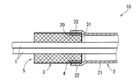
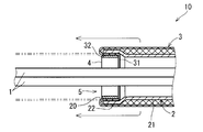
- the electric wire 10 with an electromagnetic shielding component includes an electric wire 1 and a cylindrical electromagnetic shielding component 5 that surrounds the electric wire 1.
- the side surface of the electric wire 1 is shown. 6 and 10 also show the side surfaces of the electric wire 1 in the same manner.
- the electric wire 1 is an insulated wire having a conductive core wire and an insulating coating covering the periphery of the core wire.
- the electromagnetic shield component-equipped electric wire 10 includes a plurality of electric wires 1, and the electromagnetic shield component 5 surrounds the plurality of electric wires 1.
- the electromagnetic shield component 5 includes a shield pipe 2, a flexible shield member 3, and a connecting member 4.
- the shield pipe 2 and the flexible shield member 3 form a series of hollow portions through which the electric wire 1 passes.
- the housing density of the electric wire 1 in the hollow portion of the shield pipe 2 is relatively small, that is, the gap between the inner peripheral surface of the shield pipe 2 and the outer peripheral surface of the electric wire 1 is relatively small. Large state is shown. However, in each embodiment, it is also conceivable that the electric wire 1 is accommodated in the hollow portion of the shield pipe 2 with a higher accommodation density than the illustrated state.
- the electric wire 1 may be a multi-core cable.
- the multi-core cable has a plurality of core wires and an insulation coating that insulates the plurality of core wires and covers the plurality of core wires together.
- the electromagnetic shield component 5 has a structure in which the shield pipe 2 and the flexible shield member 3 are connected by a connecting member 4, thereby forming a series of cylindrical shapes.
- the shield pipe 2 is a member that includes a metal material and is formed in a hard cylindrical shape.
- the shield pipe 2 is a metal pipe whose main component is a metal such as aluminum or stainless steel.
- the shield pipe 2 is a member in which a metal pipe and a non-conductive substance formed on a part of the metal pipe are integrated.
- the shield pipe 2 may be a pipe having a metal pipe and an insulating coating formed on a part of the inner peripheral surface and the outer peripheral surface of the metal pipe.
- the shield pipe 2 has an enlarged diameter portion 22 that forms a part from at least one of both ends thereof, and a base portion 21 that forms the other portion.
- the enlarged diameter portion 22 forms a part from one end of the shield pipe 2 ⁇ / b> A, and has an inner peripheral surface and an outer peripheral surface that are larger in diameter than the adjacent base portion 21.
- the enlarged diameter portion 22 forms a frame of the opening 20 at the end of the shield pipe 2.
- the enlarged diameter portion 22 is a portion formed from one end of the shield pipe 2 and having a larger diameter than the portion (base portion 21) where the inner peripheral surface and the outer peripheral surface are adjacent to each other. That is, the diameter of the inner peripheral surface of the enlarged diameter portion 22 is larger than the diameter of the inner peripheral surface of the base portion 21, and the diameter of the outer peripheral surface of the enlarged diameter portion 22 is larger than the diameter of the outer peripheral surface of the base portion 21.
- the shield pipe 2 is a member obtained by applying a process for expanding the diameter to a part from the end of the pipe having a uniform cross-sectional shape over the entire length. An example of the processing method will be described later.
- the base 21 of the shield pipe 2 includes a portion that is adjacent to the enlarged diameter portion 22.
- the base 21 has a tubular shape with a uniform cross-sectional shape.
- the base 21 is a straight tube or a bent tube.
- the base 21 is cylindrical.
- it cannot be considered that the base 21 is a square pipe shape.
- the enlarged diameter portion 22 of the shield pipe 2 is formed at each end of the shield pipe 2.
- the flexible shield member 3 is a member that includes a metal material and is formed in a flexible cylindrical shape.
- a typical example of the flexible shield member 3 is a braided wire.
- the braided wire is a member having a structure in which a conducting wire is knitted into a cylindrical shape.
- the conducting wire constituting the braided wire includes, for example, a wire material mainly composed of copper and plating formed on the surface of the wire material.
- the conducting wire which comprises a braided wire contains the wire which has aluminum as a main component.
- the flexible shield member 3 may be a member including a metal cloth rolled into a cylindrical shape.
- the metal cloth is a metal thread fabric.
- the metal cloth is, for example, a cloth having a network structure in which metal threads mainly composed of copper are woven so as to intersect in the longitudinal direction and the transverse direction.
- the metal cloth may have a structure in which a flexible film made of a resin material is attached to a metal yarn cloth. The metal cloth has conductivity and flexibility.
- a part near one end portion 31 forms an overlapping portion 32 that covers the inner peripheral surface side of the enlarged diameter portion 22 in the shield pipe 2.
- the flexible shield member 3 forms a series of hollow portions together with the shield pipe 2.
- a series of hollow portions formed by the shield pipe 2 and the flexible shield member 3 are wiring paths of the electric wires 1.
- the connecting member 4 is a member that connects the enlarged diameter portion 22 of the shield pipe 2 and the overlapping portion 32 of the flexible shield member 3 and is formed in an annular shape.
- the connecting member 4 is sandwiched between the overlapping portion 32 of the flexible shield member 3 and the inner peripheral surface of the enlarged diameter portion 22 in the shield pipe 2.
- the inner peripheral surface of the connecting member 4 has an oval (rounded rectangular shape) in addition to the case where the inner peripheral surface of the connecting member 4 has an elliptical shape or a perfect circular shape. ).
- the connecting member 4 is, for example, a member whose main component is iron whose surface is plated or a member whose main component is stainless steel.
- the connecting member 4 in the present embodiment is formed in an annular shape having a contour along the inner peripheral surface of the enlarged diameter portion 22 in the shield pipe 2.
- the connecting member 4 sandwiches the overlapping portion 32 of the flexible shield member 3 with the inner peripheral surface of the enlarged diameter portion 22 in the shield pipe 2.
- the connecting member 4 presses the overlapping portion 32 of the flexible shield member 3 against the inner peripheral surface of the shield pipe 2 in a range over the entire circumference.
- the inner peripheral surface of the connecting member 4 is formed to have the same diameter or more as the inner peripheral surface of the base portion 21 adjacent to the enlarged diameter portion 22 in the shield pipe 2. If it does so, the connection member 4 will not protrude inside in the hollow part of the shield pipe 2, ie, the wiring path of the electric wire 1.
- FIG. 2 it is conceivable that the inner peripheral surface of the connecting member 4 is formed to have the same diameter or more as the inner peripheral surface of the base portion 21 adjacent to the enlarged diameter portion 22 in the shield pipe 2. If it does so, the connection member 4 will not protrude inside in the hollow part of the shield pipe 2, ie, the wiring path of the electric wire 1.
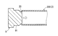
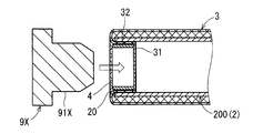
- FIG. 3 is a first longitudinal sectional view (before pipe diameter expansion processing) of the end portion of the shield pipe 2 when the electromagnetic shield component 5 is manufactured by the first method.
- FIG. 4 is a second vertical cross-sectional view (during pipe diameter expansion processing) of the end of the shield pipe when the electromagnetic shield component 5 is manufactured by the first method.
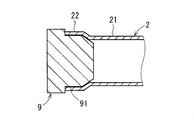
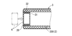
- FIG. 5 is a longitudinal sectional view (before the connecting member 4 is mounted) of the main part of the electromagnetic shielding component 5 when the electromagnetic shielding component 5 is manufactured by the first method.
- the shield pipe 2 can be obtained by subjecting the end portion of the pipe raw material 200 having a uniform cross-sectional shape over the entire length to a process of expanding the diameter.
- this processing is referred to as pipe diameter expansion processing.
- pipe diameter expansion processing is performed by using a molding metal fitting 9 having a diameter expansion molding surface 91 having a diameter larger than the inner peripheral surface of the pipe raw material 200. This is a process of pushing a part from the end of the pipe raw material 200 from the inside by inserting it into the opening 20 at the end of the material 200.
- the outer diameter of the enlarged diameter molding surface 91 is, for example, twice the total of the thickness of the annular connecting member 4 and the thickness of the flexible shield member 3 in the diameter of the inner peripheral surface of the pipe raw material 200. Same as or slightly larger than the combined diameter.
- the shield pipe 2 having the enlarged diameter portion 22 formed at the end portion is obtained by subjecting the pipe raw material 200 to the pipe diameter expansion processing.
- the inner peripheral surface of the enlarged diameter portion 22 is molded into a shape along the enlarged diameter molding surface 91 of the molding metal fitting 9.
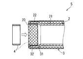
- a connecting member press-fitting step for inserting the connecting member 4 into the enlarged diameter portion 22 of the shield pipe 2 is performed. This step is performed in a state where the flexible shield member 3 is overlapped on the outer peripheral surface side of the pipe raw material 200 and a part from the end portion 31 of the flexible shield member 3 is folded back to the inside of the enlarged diameter portion 22.
- a portion of the flexible shield member 3 that is folded back to the inside of the enlarged diameter portion 22 is the overlapping portion 32.
- the outer diameter of the connecting member 4 is a diameter obtained by subtracting twice the thickness of the flexible shield member 3 from the inner diameter of the enlarged diameter portion 22. Slightly larger than.
- the connecting member 4 is, for example, a metal annular member, and does not have to have a special structure that changes and maintains its diameter.
- the connecting member press-fitting step the connecting member 4 is pushed further into the inside of the enlarged diameter portion 22 of the shield pipe 2 and the overlapping portion 32 of the flexible shield member 3 inside thereof. Thereby, the connecting member 4 is fitted inside the overlapping portion 32 while the outer diameter thereof is slightly contracted. As a result, the connecting member 4 is in a state in which the overlapping portion 32 of the flexible shield member 3 is sandwiched between the inner peripheral surface of the enlarged diameter portion 22 and fastened.
- the electric wire 1 is passed through the hollow portion of the shield pipe 2A.
- the electric wire 1 is passed through the hollow portion of the shield pipe 2A in a state where the flexible shield member 3 is overlapped on the outer peripheral surface side.
- the portion of the flexible shield member 3 that overlaps the outer peripheral surface side of the shield pipe 2A is pulled out in the extending direction of the enlarged diameter portion 22 of the shield pipe 2A. Thereby, the folding of the flexible shield member 3 is released.
- the flexible shield member 3 is pulled out as described above to cover the periphery of the portion of the electric wire 1 extending from the opening 20 of the shield pipe 2A.
- the pipe diameter expansion process is performed such that the flexible shield member 3 is overlapped on the outer peripheral surface side of the pipe raw material 200, and a part from the end portion 31 of the flexible shield member 3 is formed from the opening 20 in the pipe raw material 200. It is performed in a state in which it is folded back to the side surface and the connecting member 4 is further overlapped on the inner side.
- the pipe diameter expansion process of the second method is performed by inserting a molding fitting 9 ⁇ / b> X having a diameter expansion molding surface 91 ⁇ / b> X into the opening 20 at the end of the pipe raw material 200. 4 and a part from the end of the pipe raw material 200 are processed to spread from the inside of the connecting member 4.
- the outer diameter of the diameter-enlarged molding surface 91X is, for example, the same as or slightly larger than the inner circumferential surface of the pipe raw material 200.
- the diameter of the shield pipe 2 having the diameter-expanded portion 22 formed at the end and the overlapping portion 32 of the flexible shield member 3 with the diameter increased are increased.
- the connecting member 4 that is sandwiched between and fastened is obtained at the same time.
- the procedure after the pipe diameter increasing process in the second method is the same as the procedure after the connecting member press-fitting step in the first method (see FIG. 6).
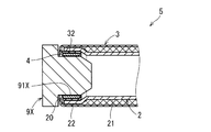
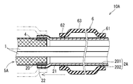
- FIG. 10 is a longitudinal sectional view of the main part of the electric wire with electromagnetic shield part 10A. 10, the same components as those shown in FIGS. 1 to 9 are given the same reference numerals.
- the electromagnetic shielding component-attached electric wire 10 ⁇ / b> A includes a shield pipe 2 ⁇ / b> A with a resin coating instead of the shielding pipe 2 and a grommet 6. The point is different.
- the difference in the electromagnetic shield component-equipped electric wire 10A from the electromagnetic shield component-equipped electric wire 10 will be described.
- the electric wire with electromagnetic shield part 10 ⁇ / b> A is also provided with the electric wire 1 and an electromagnetic shield part 5 ⁇ / b> A surrounding the electric wire 1, similarly to the electric wire with electromagnetic shield part 10.
- the electromagnetic shield component 5 ⁇ / b> A includes a shield pipe 2 ⁇ / b> A, a flexible shield member 3, and a connecting member 4.
- the shield pipe 2 ⁇ / b> A is a pipe having a metal pipe 201 and an insulating coating 202 formed on the outer peripheral surface of the metal pipe 201.
- the metal pipe 201 is a pipe mainly composed of a metal such as aluminum or stainless steel.
- the insulating coating 202 is, for example, a synthetic resin or a coating film of a rubber-based material.
- the shield pipe 2A has the same structure as the shield pipe 2 except that the insulating coating 202 is formed.
- the electric wire with electromagnetic shielding component 10A also includes a grommet 6 that is a non-conductive cylindrical elastic member.
- the grommet 6 is a member whose main component is a rubber material such as rubber or elastomer.
- the grommet 6 is a member for preventing the liquid from entering the flexible shield member 3 when the electric wire with electromagnetic shield part 10A is attached to a support body such as a vehicle body.
- the grommet 6 includes a first closing portion 61 that occupies a portion near one end thereof, a second closing portion 62 that occupies a portion near the other end, and an intermediate portion 63 therebetween.
- the first blocking portion 61 is a portion that is covered with the shield pipe 2A in close contact with the outer peripheral surface of the enlarged diameter portion 22.
- occlusion part 62 is covered with the frame part (not shown) formed around the opening which comprises the path
- the frame portion is formed, for example, around the opening of a housing that houses the device to which the electric wire 1 is connected.
- the inner peripheral surface of the first closing portion 61 has a larger diameter than the outer peripheral surface of the base portion 21 (portion adjacent to the enlarged diameter portion 22) in the shield pipe 2A and the enlarged diameter portion 22. It is formed with a smaller diameter than the outer peripheral surface.
- the natural state grommet means a grommet in a state where no external force is applied.
- the inner peripheral surface of the intermediate portion 63 connected to the first closing portion 61 is formed with a larger diameter than the outer peripheral surface of the enlarged diameter portion 22 in the shield pipe 2A.
- the entire inner peripheral surface of the grommet 6 is formed with a larger diameter than the outer peripheral surface of the base portion 21 of the shield pipe 2A.
- the electromagnetic shield component 5A When the electromagnetic shield component 5A is attached to a support such as a vehicle body, it is necessary to move the grommet 6 along the outer peripheral surface of the shield pipe 2A.
- the frictional resistance between the grommet 6 and the shield pipe 2 ⁇ / b> A is very small except when the first closing portion 61 passes through the enlarged diameter portion 22. Therefore, the grommet 6 can be moved along the shield pipe 2 ⁇ / b> A with a very small force except when the first closing portion 61 passes through the enlarged diameter portion 22.
- the grommet 6 is temporarily fastened to the shield pipe 2 ⁇ / b> A so that the entire grommet 6 surrounds the base 21 of the shield pipe 2 ⁇ / b> A, and then the first closed portion 61 is in close contact with the outer peripheral surface of the enlarged diameter portion 22. Moved to position.
- the temporary fastening state of the grommet 6 to the shield pipe 2 ⁇ / b> A may be a state in which the first closing portion 61 surrounds the base portion 21 and the intermediate portion 63 surrounds the enlarged diameter portion 22.
- the end portions of the hard shield pipes 2 and 2A containing a metal material are formed with an enlarged diameter portion 22 having a larger diameter than the adjacent base portion 21.
- the flexible shield member 3 is inserted
- a strong flexible shield member 3 containing a metal material is interposed between the electric wire 1 and the end portions of the shield pipes 2 and 2A to prevent the electric wire 1 from being damaged. For this reason, it is not necessary to cover the edges of the shield pipes 2 and 2A.
- the electromagnetic shielding components 5 and 5A are employed, even if the gap between the inner peripheral surface of the base 21 (the portion other than the enlarged diameter portion 22) of the shield pipes 2 and 2A and the outer peripheral surface of the electric wire 1 is small. In the enlarged diameter portion 22, it is possible to ensure a gap enough to insert the connecting member 4 that holds the flexible shield member 3. Therefore, even if the accommodation density of the electric wire 1 in the hollow portion of the shield pipes 2 and 2A (hard pipe) is increased, the flexible shield member 3 can be connected to the shield pipes 2 and 2A without any problem.
- the electromagnetic shielding parts 5 and 5A are employed, as shown in FIG. 6, in the step of passing the electric wire 1 through the hollow part of the electromagnetic shielding parts 5 and 5A, the electric wire 1 is inserted into the hollow part of the flexible shielding member 3 There is no need to penetrate from the end. As a result, the electric wire 1 can be easily passed through the hollow portions of the electromagnetic shielding components 5 and 5A.
- the inner peripheral surface of the connecting member 4 is formed with the same diameter or more as the inner peripheral surface of the base portion 21 of the shield pipes 2 and 2A, the enlarged diameter portion of the shield pipes 2 and 2A.
- the inner peripheral surface of the connecting member 4 inserted into 22 does not protrude inward from the extended surface of the inner peripheral surface of the base portion 21 of the shield pipes 2 and 2A. Therefore, the accommodation density of the electric wire 1 in the hollow part of the shield pipes 2 and 2A (hard pipe) can be further increased. Further, when the electric wire 1 is passed through the hollow portions of the shield pipes 2 and 2 ⁇ / b> A, the electric wire 1 is not easily caught by the connecting member 4.
- the insulating coating 202 prevents electric shock even when a high voltage is generated in the metal pipe 201.
- the flexible shield member 3 is in contact with the inner peripheral surface of the metal pipe 201 (shield pipe 2A). Therefore, the insulating coating 202 of the shield pipe 2 ⁇ / b> A does not hinder the electrical connection between the metal pipe 201 and the flexible shield member 3.
- the pipe machining process (pipe diameter machining process) for creating the enlarged diameter portion 22 of the shield pipes 2 and 2A is performed by the connecting member 4. It can also serve as an attachment process. Thereby, the manufacturing process of electromagnetic shielding components 5 and 5A can be simplified.
- the flexible shield member 3 can be fastened to the shield pipes 2 and 2A using a very simple connecting member 4.
- the grommet 6 can be moved with a very small force in the operation of moving the grommet 6 along the outer peripheral surface of the shield pipe 2A. As a result, the work of attaching the electromagnetic shielding component 5A including the grommet 6 to the support becomes easy.
- the electromagnetic shielding component and the electric wire with electromagnetic shielding component according to the present invention can be freely combined with each of the embodiments and application examples described above within the scope of the invention described in each claim, or each embodiment. Further, the present invention can be configured by appropriately modifying or omitting some of the application examples.
Landscapes
- Engineering & Computer Science (AREA)
- Microelectronics & Electronic Packaging (AREA)
- Architecture (AREA)
- Civil Engineering (AREA)
- Structural Engineering (AREA)
- Shielding Devices Or Components To Electric Or Magnetic Fields (AREA)
- Insulated Conductors (AREA)
- Details Of Indoor Wiring (AREA)
Abstract
L'objectif de la présente invention est d'accomplir, dans un composant de blindage électromagnétique, même si la densité de maintien des fils électriques à l'intérieur de la partie creuse d'un tuyau rigide est augmentée, une prévention des dommages à un fil électrique dus à un contact avec un bord du tuyau, sans nécessiter de composant supplémentaire tel qu'un couvercle d'extrémité de tuyau. Au niveau d'une partie de l'une des extrémités, le tuyau de blindage comporte une partie de diamètre élargi dans laquelle une surface périphérique interne et une surface périphérique externe ont été formées avec des diamètres qui sont plus grands que ceux d'une partie adjacente continue. Un élément d'accouplement en forme d'anneau et la surface périphérique interne du tuyau de blindage prennent en sandwich et fixent entre eux une partie de chevauchement d'un élément de blindage souple, qui coïncide avec la partie de diamètre élargi sur le côté de surface périphérique interne de celui-ci.
Priority Applications (3)
| Application Number | Priority Date | Filing Date | Title |
|---|---|---|---|
| DE112015000697.4T DE112015000697T5 (de) | 2014-02-06 | 2015-01-20 | Komponente zur elektromagnetischen Abschirmung und elektrische Leitungsanordnung mit Komponente zur elektromagnetischen Abschirmung |
| US15/116,906 US9743567B2 (en) | 2014-02-06 | 2015-01-20 | Electromagnetic shielding component and electric wire assembly with electromagnetic shielding component |
| CN201580007082.5A CN106030726B (zh) | 2014-02-06 | 2015-01-20 | 电磁屏蔽部件和具有电磁屏蔽部件的电线 |
Applications Claiming Priority (2)
| Application Number | Priority Date | Filing Date | Title |
|---|---|---|---|
| JP2014-021146 | 2014-02-06 | ||
| JP2014021146A JP6191489B2 (ja) | 2014-02-06 | 2014-02-06 | 電磁シールド部品および電磁シールド部品付電線 |
Publications (1)
| Publication Number | Publication Date |
|---|---|
| WO2015118937A1 true WO2015118937A1 (fr) | 2015-08-13 |
Family
ID=53777744
Family Applications (1)
| Application Number | Title | Priority Date | Filing Date |
|---|---|---|---|
| PCT/JP2015/051350 WO2015118937A1 (fr) | 2014-02-06 | 2015-01-20 | Composant de blindage électromagnétique et fil électrique avec le composant de blindage électromagnétique |
Country Status (5)
| Country | Link |
|---|---|
| US (1) | US9743567B2 (fr) |
| JP (1) | JP6191489B2 (fr) |
| CN (1) | CN106030726B (fr) |
| DE (1) | DE112015000697T5 (fr) |
| WO (1) | WO2015118937A1 (fr) |
Cited By (3)
| Publication number | Priority date | Publication date | Assignee | Title |
|---|---|---|---|---|
| WO2017199814A1 (fr) * | 2016-05-20 | 2017-11-23 | 株式会社オートネットワーク技術研究所 | Élément écran électromagnétique, module de câblage et procédé de fabrication d'un élément écran électromagnétique |
| WO2017204036A1 (fr) * | 2016-05-25 | 2017-11-30 | 株式会社オートネットワーク技術研究所 | Élément d'écran électromagnétique, module de câblage et procédé de fabrication d'un élément d'écran électromagnétique |
| US20180233257A1 (en) * | 2017-02-10 | 2018-08-16 | Sumitomo Wiring Systems, Ltd. | Wire harness protection structure and method for producing braided cover-equipped wire harness |
Families Citing this family (8)
| Publication number | Priority date | Publication date | Assignee | Title |
|---|---|---|---|---|
| JP6361544B2 (ja) * | 2015-03-24 | 2018-07-25 | 株式会社オートネットワーク技術研究所 | 電磁シールド部材 |
| JP2018120788A (ja) * | 2017-01-26 | 2018-08-02 | 住友電装株式会社 | ワイヤハーネス及びワイヤハーネスの接続構造 |
| JP6816660B2 (ja) * | 2017-06-15 | 2021-01-20 | 株式会社オートネットワーク技術研究所 | 電磁シールド部品、ワイヤハーネス及び電磁シールド部品の製造方法 |
| US10147216B1 (en) * | 2017-11-01 | 2018-12-04 | Essential Products, Inc. | Intelligent camera |
| US10985538B2 (en) * | 2018-05-25 | 2021-04-20 | Leoni Bordnetz-Systeme Gmbh | System and method for reducing air volume in a splitter |
| JP7256456B2 (ja) * | 2019-08-08 | 2023-04-12 | 株式会社オートネットワーク技術研究所 | ワイヤハーネス |
| JP7385524B2 (ja) * | 2020-04-28 | 2023-11-22 | ニデックインスツルメンツ株式会社 | モータ |
| CN112930102B (zh) * | 2021-01-22 | 2022-10-14 | 西安应用光学研究所 | 柔性气密性电磁屏蔽装置 |
Citations (5)
| Publication number | Priority date | Publication date | Assignee | Title |
|---|---|---|---|---|
| JP2006310516A (ja) * | 2005-04-28 | 2006-11-09 | Auto Network Gijutsu Kenkyusho:Kk | シールド導電路 |
| JP2006311699A (ja) * | 2005-04-28 | 2006-11-09 | Auto Network Gijutsu Kenkyusho:Kk | シールド導電路 |
| JP2008071645A (ja) * | 2006-09-14 | 2008-03-27 | Auto Network Gijutsu Kenkyusho:Kk | 導電体及びその製造方法 |
| JP2008226530A (ja) * | 2007-03-09 | 2008-09-25 | Yazaki Corp | シールドパイプ |
| JP2013114785A (ja) * | 2011-11-25 | 2013-06-10 | Yazaki Corp | ワイヤハーネス |
Family Cites Families (17)
| Publication number | Priority date | Publication date | Assignee | Title |
|---|---|---|---|---|
| JP3409243B2 (ja) * | 1998-03-10 | 2003-05-26 | 住友電装株式会社 | グロメット |
| US6545220B2 (en) * | 2001-08-31 | 2003-04-08 | Hewlett-Packard Company | Shielded cable system for high speed cable termination |
| JP4823561B2 (ja) | 2005-04-28 | 2011-11-24 | 株式会社オートネットワーク技術研究所 | シールド導電路 |
| JP2007012515A (ja) * | 2005-07-01 | 2007-01-18 | Auto Network Gijutsu Kenkyusho:Kk | シールド導電体 |
| JP5002182B2 (ja) | 2006-04-07 | 2012-08-15 | 株式会社オートネットワーク技術研究所 | シールド導電路 |
| JP2009059505A (ja) * | 2007-08-30 | 2009-03-19 | Auto Network Gijutsu Kenkyusho:Kk | シールド導電体 |
| US7692096B2 (en) * | 2007-12-07 | 2010-04-06 | Delphi Technologies, Inc. | Electromagnetically shielded cable |
| JP5566716B2 (ja) * | 2010-02-05 | 2014-08-06 | 矢崎総業株式会社 | ワイヤハーネス |
| JP5607412B2 (ja) * | 2010-04-15 | 2014-10-15 | 矢崎総業株式会社 | ワイヤハーネス |
| JP5350323B2 (ja) * | 2010-06-02 | 2013-11-27 | 矢崎総業株式会社 | 編組シールド部材、編組シールド部材の製造方法、及びワイヤハーネス |
| JP5586335B2 (ja) * | 2010-06-10 | 2014-09-10 | 矢崎総業株式会社 | シールド端末接続構造及び方法 |
| JP5722562B2 (ja) * | 2010-07-21 | 2015-05-20 | 矢崎総業株式会社 | シールド部材、ワイヤハーネス、及びワイヤハーネス製造方法 |
| JP2012178314A (ja) * | 2011-02-28 | 2012-09-13 | Auto Network Gijutsu Kenkyusho:Kk | シールド導電体 |
| JP6062812B2 (ja) * | 2013-06-17 | 2017-01-18 | 矢崎総業株式会社 | シールドユニット |
| JP6086323B2 (ja) * | 2013-10-04 | 2017-03-01 | 住友電装株式会社 | シールドパイプ |
| JP6132206B2 (ja) * | 2014-03-03 | 2017-05-24 | 住友電装株式会社 | シールド導電路 |
| JP6210381B2 (ja) * | 2014-08-22 | 2017-10-11 | 住友電装株式会社 | シールド導電路 |
-
2014
- 2014-02-06 JP JP2014021146A patent/JP6191489B2/ja not_active Expired - Fee Related
-
2015
- 2015-01-20 WO PCT/JP2015/051350 patent/WO2015118937A1/fr active Application Filing
- 2015-01-20 US US15/116,906 patent/US9743567B2/en active Active
- 2015-01-20 DE DE112015000697.4T patent/DE112015000697T5/de not_active Withdrawn
- 2015-01-20 CN CN201580007082.5A patent/CN106030726B/zh not_active Expired - Fee Related
Patent Citations (5)
| Publication number | Priority date | Publication date | Assignee | Title |
|---|---|---|---|---|
| JP2006310516A (ja) * | 2005-04-28 | 2006-11-09 | Auto Network Gijutsu Kenkyusho:Kk | シールド導電路 |
| JP2006311699A (ja) * | 2005-04-28 | 2006-11-09 | Auto Network Gijutsu Kenkyusho:Kk | シールド導電路 |
| JP2008071645A (ja) * | 2006-09-14 | 2008-03-27 | Auto Network Gijutsu Kenkyusho:Kk | 導電体及びその製造方法 |
| JP2008226530A (ja) * | 2007-03-09 | 2008-09-25 | Yazaki Corp | シールドパイプ |
| JP2013114785A (ja) * | 2011-11-25 | 2013-06-10 | Yazaki Corp | ワイヤハーネス |
Cited By (4)
| Publication number | Priority date | Publication date | Assignee | Title |
|---|---|---|---|---|
| WO2017199814A1 (fr) * | 2016-05-20 | 2017-11-23 | 株式会社オートネットワーク技術研究所 | Élément écran électromagnétique, module de câblage et procédé de fabrication d'un élément écran électromagnétique |
| CN109156094A (zh) * | 2016-05-20 | 2019-01-04 | 株式会社自动网络技术研究所 | 电磁屏蔽构件、布线模块以及电磁屏蔽构件的制造方法 |
| WO2017204036A1 (fr) * | 2016-05-25 | 2017-11-30 | 株式会社オートネットワーク技術研究所 | Élément d'écran électromagnétique, module de câblage et procédé de fabrication d'un élément d'écran électromagnétique |
| US20180233257A1 (en) * | 2017-02-10 | 2018-08-16 | Sumitomo Wiring Systems, Ltd. | Wire harness protection structure and method for producing braided cover-equipped wire harness |
Also Published As
| Publication number | Publication date |
|---|---|
| CN106030726A (zh) | 2016-10-12 |
| CN106030726B (zh) | 2017-12-05 |
| JP6191489B2 (ja) | 2017-09-06 |
| DE112015000697T5 (de) | 2016-10-20 |
| US20170181337A1 (en) | 2017-06-22 |
| JP2015149176A (ja) | 2015-08-20 |
| US9743567B2 (en) | 2017-08-22 |
Similar Documents
| Publication | Publication Date | Title |
|---|---|---|
| JP6191489B2 (ja) | 電磁シールド部品および電磁シールド部品付電線 | |
| JP5935787B2 (ja) | ワイヤハーネス及びワイヤハーネス製造方法 | |
| US9718365B2 (en) | Wiring member | |
| US7491071B2 (en) | Shield end processing structure | |
| WO2015093293A1 (fr) | Câble électrique équipé d'un matériau de protection | |
| JP2003115223A (ja) | 電磁波シールド編組 | |
| JP2012113949A (ja) | シールド導電体 | |
| JP2012104727A (ja) | シールド管、シールド管の製造方法、ケーブルスペーサ付シールド管とその敷設方法 | |
| JP6610946B2 (ja) | シールド導電路 | |
| JP6156173B2 (ja) | 電磁シールド部品 | |
| CN109644583B (zh) | 电磁屏蔽部件及导电路径 | |
| JP2006269666A (ja) | シールド構造体 | |
| JP2017204515A (ja) | 電磁シールド部品、電磁シールド部品付き電線、及び電磁シールド部品の製造方法 | |
| WO2019220905A1 (fr) | Faisceau de fils conducteurs | |
| JP2015065783A (ja) | ワイヤハーネス | |
| CN110323635A (zh) | 形状保持的电缆组件 | |
| JP6409672B2 (ja) | 電線モジュール | |
| JP6398255B2 (ja) | 電磁シールド部材 | |
| WO2015159667A1 (fr) | Dispositif de blindage électromagnétique et faisceau de fils | |
| JP6229805B2 (ja) | シールド導電路 | |
| JP2016062675A (ja) | ワイヤーハーネス | |
| JP2013222645A (ja) | 電磁シールド具及びワイヤハーネス | |
| WO2016052103A1 (fr) | Élément de blindage électromagnétique | |
| JP2016072551A (ja) | 電磁シールド部材 | |
| JP2016201297A (ja) | コネクタ付電線及び外装部材 |
Legal Events
| Date | Code | Title | Description |
|---|---|---|---|
| 121 | Ep: the epo has been informed by wipo that ep was designated in this application |
Ref document number: 15746594 Country of ref document: EP Kind code of ref document: A1 |
|
| WWE | Wipo information: entry into national phase |
Ref document number: 15116906 Country of ref document: US |
|
| WWE | Wipo information: entry into national phase |
Ref document number: 112015000697 Country of ref document: DE |
|
| 122 | Ep: pct application non-entry in european phase |
Ref document number: 15746594 Country of ref document: EP Kind code of ref document: A1 |