WO2015118937A1 - Electromagnetic shielding component and electric wire with electromagnetic shielding component - Google Patents
Electromagnetic shielding component and electric wire with electromagnetic shielding component Download PDFInfo
- Publication number
- WO2015118937A1 WO2015118937A1 PCT/JP2015/051350 JP2015051350W WO2015118937A1 WO 2015118937 A1 WO2015118937 A1 WO 2015118937A1 JP 2015051350 W JP2015051350 W JP 2015051350W WO 2015118937 A1 WO2015118937 A1 WO 2015118937A1
- Authority
- WO
- WIPO (PCT)
- Prior art keywords
- shield
- pipe
- peripheral surface
- electric wire
- electromagnetic shielding
- Prior art date
Links
Images

Classifications
-
- H—ELECTRICITY
- H05—ELECTRIC TECHNIQUES NOT OTHERWISE PROVIDED FOR
- H05K—PRINTED CIRCUITS; CASINGS OR CONSTRUCTIONAL DETAILS OF ELECTRIC APPARATUS; MANUFACTURE OF ASSEMBLAGES OF ELECTRICAL COMPONENTS
- H05K9/00—Screening of apparatus or components against electric or magnetic fields
- H05K9/0073—Shielding materials
- H05K9/0098—Shielding materials for shielding electrical cables
-
- H—ELECTRICITY
- H01—ELECTRIC ELEMENTS
- H01R—ELECTRICALLY-CONDUCTIVE CONNECTIONS; STRUCTURAL ASSOCIATIONS OF A PLURALITY OF MUTUALLY-INSULATED ELECTRICAL CONNECTING ELEMENTS; COUPLING DEVICES; CURRENT COLLECTORS
- H01R13/00—Details of coupling devices of the kinds covered by groups H01R12/70 or H01R24/00 - H01R33/00
- H01R13/648—Protective earth or shield arrangements on coupling devices, e.g. anti-static shielding
- H01R13/658—High frequency shielding arrangements, e.g. against EMI [Electro-Magnetic Interference] or EMP [Electro-Magnetic Pulse]
- H01R13/6591—Specific features or arrangements of connection of shield to conductive members
- H01R13/6592—Specific features or arrangements of connection of shield to conductive members the conductive member being a shielded cable
-
- H—ELECTRICITY
- H02—GENERATION; CONVERSION OR DISTRIBUTION OF ELECTRIC POWER
- H02G—INSTALLATION OF ELECTRIC CABLES OR LINES, OR OF COMBINED OPTICAL AND ELECTRIC CABLES OR LINES
- H02G3/00—Installations of electric cables or lines or protective tubing therefor in or on buildings, equivalent structures or vehicles
- H02G3/02—Details
- H02G3/04—Protective tubing or conduits, e.g. cable ladders or cable troughs
- H02G3/0462—Tubings, i.e. having a closed section
-
- H—ELECTRICITY
- H02—GENERATION; CONVERSION OR DISTRIBUTION OF ELECTRIC POWER
- H02G—INSTALLATION OF ELECTRIC CABLES OR LINES, OR OF COMBINED OPTICAL AND ELECTRIC CABLES OR LINES
- H02G3/00—Installations of electric cables or lines or protective tubing therefor in or on buildings, equivalent structures or vehicles
- H02G3/02—Details
- H02G3/06—Joints for connecting lengths of protective tubing or channels, to each other or to casings, e.g. to distribution boxes; Ensuring electrical continuity in the joint
-
- H—ELECTRICITY
- H05—ELECTRIC TECHNIQUES NOT OTHERWISE PROVIDED FOR
- H05K—PRINTED CIRCUITS; CASINGS OR CONSTRUCTIONAL DETAILS OF ELECTRIC APPARATUS; MANUFACTURE OF ASSEMBLAGES OF ELECTRICAL COMPONENTS
- H05K9/00—Screening of apparatus or components against electric or magnetic fields
- H05K9/0007—Casings
- H05K9/0018—Casings with provisions to reduce aperture leakages in walls, e.g. terminals, connectors, cables
Definitions
- the present invention relates to an electromagnetic shield component including a hard shield pipe and a flexible shield member, and an electric wire with an electromagnetic shield component including the same.
- an electromagnetic shielding part surrounding the wire may be employed.
- the electromagnetic shielding component has a hard metal pipe and a cylindrical braided wire connected thereto.
- the metal pipe performs an electromagnetic shielding function, physically protects the electric wire, and further maintains the electric wire in a shape along a predetermined wiring path.
- the braided wire is a member formed in a cylindrical shape by knitting copper wire, it has flexibility.
- the braided wire having flexibility fulfills an electromagnetic shielding function and enables bending deformation of a portion near the end of the electric wire.
- a metal pipe and a braided wire are usually connected by caulking.
- the metal pipe in the caulking, the metal pipe is fastened from the outer peripheral surface side, and a part of the braided wire covering the outer peripheral surface near the end of the metal pipe is sandwiched between the metal pipe. Thereby, the part near the end of the braided wire stays on the outer peripheral surface side of the part near the end of the metal pipe.
- the braided wire is sandwiched between the outer peripheral surface of the support member inserted into the metal pipe and the inner peripheral surface of the crimped portion (compressed portion) of the metal pipe. Thereby, the part near the end of the braided wire stays on the inner peripheral surface side of the part near the end of the metal pipe.
- the end face of the metal pipe exists inside the braided wire.
- the electric wire passed through the hollow portion of the metal pipe may be damaged by contact with the edge of the end surface of the metal pipe.
- a general electromagnetic shielding component is provided with an edge cover that covers the end of the metal pipe.
- an edge cover that covers the end of the metal pipe.
- the present invention relates to an electromagnetic shield component, and even if the housing density of the electric wire in the hollow portion of the hard pipe is increased, the electric wire is damaged due to contact with the edge of the pipe without requiring an additional component such as a cover at the end of the pipe.
- the purpose is to prevent.
- the electromagnetic shielding component includes a shield pipe, a flexible shield member, and a connecting member.
- the shield pipe is a member that includes a metal material and is formed in a hard cylindrical shape.
- the shield pipe has an enlarged diameter portion formed with a diameter larger than that of a portion where the inner peripheral surface and the outer peripheral surface are adjacent to each other in a part from one end.
- the flexible shield member is a member that includes a metal material and is formed in a flexible cylindrical shape. In the flexible shield member, a part near one end forms an overlapping portion overlapping the inner peripheral surface side of the enlarged diameter portion of the shield pipe.
- the flexible shield member forms a series of hollow portions together with the shield pipe.
- the connecting member is a member that is formed in an annular shape and sandwiches and holds the overlapping portion of the flexible shield member between the inner peripheral surface of the shield pipe.
- the electromagnetic shielding component according to the second aspect is an aspect of the electromagnetic shielding component according to the first aspect.
- the inner peripheral surface of the connecting member is formed to have the same diameter or more as the inner peripheral surface of the portion that is adjacent to the enlarged diameter portion of the shield pipe.
- the electromagnetic shielding component according to the third aspect is one aspect of the electromagnetic shielding component according to the first aspect or the second aspect.
- the shield pipe has a metal pipe and an insulating coating formed on the outer peripheral surface of the metal pipe.
- the electromagnetic shielding component according to the fourth aspect is an aspect of the electromagnetic shielding component according to any one of the first aspect to the third aspect.
- the electromagnetic shielding component according to the fourth aspect further includes a grommet that is a non-conductive cylindrical elastic member. In the natural state, the grommet has a larger inner peripheral surface of the portion near one end surrounding the periphery of a part of the shield pipe than the outer peripheral surface of the portion adjacent to the enlarged diameter portion in the shield pipe, And it is formed with the diameter smaller than the outer peripheral surface of the said enlarged diameter part.
- the electric wire with an electromagnetic shielding component according to the fifth aspect includes an electric wire and an electromagnetic shielding component according to any one of the above aspects.
- the cylindrical electromagnetic shielding component surrounds the periphery of the electric wire.
- an end portion of a hard shield pipe containing a metal material is formed with an enlarged portion formed with a larger diameter than the adjacent portion.
- the flexible shield member is pinched
- a strong flexible shield member containing a metal material is interposed between the electric wire and the end of the shield pipe to prevent the electric wire from being damaged. Therefore, it is not necessary to cover the edge of the shield pipe.
- the step of passing the electric wire through the hollow portion of the electromagnetic shielding component it is not necessary to penetrate the electric wire from the end of the hollow portion of the flexible shield member. As a result, the electric wire can be easily passed through the hollow portion of the electromagnetic shielding component.
- the internal peripheral surface of the connection member inserted in the enlarged diameter part of a shield pipe does not protrude inward from the extension surface of the internal peripheral surface of the part which adjoins the enlarged diameter part in a shield pipe. . Therefore, the accommodation density of the electric wire in the hollow part of a shield pipe (hard pipe) can be raised more. Further, when the electric wire is passed through the hollow portion of the shield pipe, the electric wire is not easily caught by the connecting member.
- the shield pipe has a metal pipe and an insulating coating formed on the outer peripheral surface of the metal pipe.
- the insulating coating prevents electric shock even when a high voltage is generated in the metal pipe.
- the flexible shield member is in contact with the inner peripheral surface of the metal pipe (shield pipe). Therefore, the insulating coating of the shield pipe does not hinder the electrical connection between the metal pipe and the flexible shield member.
- the grommet is a member for preventing liquid from entering the flexible shield part, and a portion near one end of the grommet is covered with the shield pipe in close contact with the outer peripheral surface of the enlarged diameter part. It is a closed part.
- the inner peripheral surface of the closing portion in the grommet is formed with a diameter larger than the outer peripheral surface of the portion adjacent to the enlarged diameter portion in the shield pipe and smaller than the outer peripheral surface of the enlarged diameter portion.
- the closed portion of the grommet is formed with a larger diameter than the outer peripheral surface of the portion that is adjacent to the enlarged diameter portion of the shield pipe. Therefore, in the operation of moving the grommet along the outer peripheral surface of the shield pipe, the grommet can be moved with a very small force except when the closed portion of the grommet passes through the enlarged diameter portion of the shield pipe. As a result, the work of attaching the electromagnetic shielding component including the grommet to the support becomes easy.
- the electric wire with electromagnetic shielding components according to each embodiment is provided as a wire harness mounted on a vehicle such as an automobile.
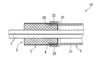
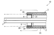
- the electric wire 10 with an electromagnetic shielding component includes an electric wire 1 and a cylindrical electromagnetic shielding component 5 that surrounds the electric wire 1.
- the side surface of the electric wire 1 is shown. 6 and 10 also show the side surfaces of the electric wire 1 in the same manner.
- the electric wire 1 is an insulated wire having a conductive core wire and an insulating coating covering the periphery of the core wire.
- the electromagnetic shield component-equipped electric wire 10 includes a plurality of electric wires 1, and the electromagnetic shield component 5 surrounds the plurality of electric wires 1.
- the electromagnetic shield component 5 includes a shield pipe 2, a flexible shield member 3, and a connecting member 4.
- the shield pipe 2 and the flexible shield member 3 form a series of hollow portions through which the electric wire 1 passes.
- the housing density of the electric wire 1 in the hollow portion of the shield pipe 2 is relatively small, that is, the gap between the inner peripheral surface of the shield pipe 2 and the outer peripheral surface of the electric wire 1 is relatively small. Large state is shown. However, in each embodiment, it is also conceivable that the electric wire 1 is accommodated in the hollow portion of the shield pipe 2 with a higher accommodation density than the illustrated state.
- the electric wire 1 may be a multi-core cable.
- the multi-core cable has a plurality of core wires and an insulation coating that insulates the plurality of core wires and covers the plurality of core wires together.
- the electromagnetic shield component 5 has a structure in which the shield pipe 2 and the flexible shield member 3 are connected by a connecting member 4, thereby forming a series of cylindrical shapes.
- the shield pipe 2 is a member that includes a metal material and is formed in a hard cylindrical shape.
- the shield pipe 2 is a metal pipe whose main component is a metal such as aluminum or stainless steel.
- the shield pipe 2 is a member in which a metal pipe and a non-conductive substance formed on a part of the metal pipe are integrated.
- the shield pipe 2 may be a pipe having a metal pipe and an insulating coating formed on a part of the inner peripheral surface and the outer peripheral surface of the metal pipe.
- the shield pipe 2 has an enlarged diameter portion 22 that forms a part from at least one of both ends thereof, and a base portion 21 that forms the other portion.
- the enlarged diameter portion 22 forms a part from one end of the shield pipe 2 ⁇ / b> A, and has an inner peripheral surface and an outer peripheral surface that are larger in diameter than the adjacent base portion 21.
- the enlarged diameter portion 22 forms a frame of the opening 20 at the end of the shield pipe 2.
- the enlarged diameter portion 22 is a portion formed from one end of the shield pipe 2 and having a larger diameter than the portion (base portion 21) where the inner peripheral surface and the outer peripheral surface are adjacent to each other. That is, the diameter of the inner peripheral surface of the enlarged diameter portion 22 is larger than the diameter of the inner peripheral surface of the base portion 21, and the diameter of the outer peripheral surface of the enlarged diameter portion 22 is larger than the diameter of the outer peripheral surface of the base portion 21.
- the shield pipe 2 is a member obtained by applying a process for expanding the diameter to a part from the end of the pipe having a uniform cross-sectional shape over the entire length. An example of the processing method will be described later.
- the base 21 of the shield pipe 2 includes a portion that is adjacent to the enlarged diameter portion 22.
- the base 21 has a tubular shape with a uniform cross-sectional shape.
- the base 21 is a straight tube or a bent tube.
- the base 21 is cylindrical.
- it cannot be considered that the base 21 is a square pipe shape.
- the enlarged diameter portion 22 of the shield pipe 2 is formed at each end of the shield pipe 2.
- the flexible shield member 3 is a member that includes a metal material and is formed in a flexible cylindrical shape.
- a typical example of the flexible shield member 3 is a braided wire.
- the braided wire is a member having a structure in which a conducting wire is knitted into a cylindrical shape.
- the conducting wire constituting the braided wire includes, for example, a wire material mainly composed of copper and plating formed on the surface of the wire material.
- the conducting wire which comprises a braided wire contains the wire which has aluminum as a main component.
- the flexible shield member 3 may be a member including a metal cloth rolled into a cylindrical shape.
- the metal cloth is a metal thread fabric.
- the metal cloth is, for example, a cloth having a network structure in which metal threads mainly composed of copper are woven so as to intersect in the longitudinal direction and the transverse direction.
- the metal cloth may have a structure in which a flexible film made of a resin material is attached to a metal yarn cloth. The metal cloth has conductivity and flexibility.
- a part near one end portion 31 forms an overlapping portion 32 that covers the inner peripheral surface side of the enlarged diameter portion 22 in the shield pipe 2.
- the flexible shield member 3 forms a series of hollow portions together with the shield pipe 2.
- a series of hollow portions formed by the shield pipe 2 and the flexible shield member 3 are wiring paths of the electric wires 1.
- the connecting member 4 is a member that connects the enlarged diameter portion 22 of the shield pipe 2 and the overlapping portion 32 of the flexible shield member 3 and is formed in an annular shape.
- the connecting member 4 is sandwiched between the overlapping portion 32 of the flexible shield member 3 and the inner peripheral surface of the enlarged diameter portion 22 in the shield pipe 2.
- the inner peripheral surface of the connecting member 4 has an oval (rounded rectangular shape) in addition to the case where the inner peripheral surface of the connecting member 4 has an elliptical shape or a perfect circular shape. ).
- the connecting member 4 is, for example, a member whose main component is iron whose surface is plated or a member whose main component is stainless steel.
- the connecting member 4 in the present embodiment is formed in an annular shape having a contour along the inner peripheral surface of the enlarged diameter portion 22 in the shield pipe 2.
- the connecting member 4 sandwiches the overlapping portion 32 of the flexible shield member 3 with the inner peripheral surface of the enlarged diameter portion 22 in the shield pipe 2.
- the connecting member 4 presses the overlapping portion 32 of the flexible shield member 3 against the inner peripheral surface of the shield pipe 2 in a range over the entire circumference.
- the inner peripheral surface of the connecting member 4 is formed to have the same diameter or more as the inner peripheral surface of the base portion 21 adjacent to the enlarged diameter portion 22 in the shield pipe 2. If it does so, the connection member 4 will not protrude inside in the hollow part of the shield pipe 2, ie, the wiring path of the electric wire 1.
- FIG. 2 it is conceivable that the inner peripheral surface of the connecting member 4 is formed to have the same diameter or more as the inner peripheral surface of the base portion 21 adjacent to the enlarged diameter portion 22 in the shield pipe 2. If it does so, the connection member 4 will not protrude inside in the hollow part of the shield pipe 2, ie, the wiring path of the electric wire 1.
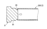
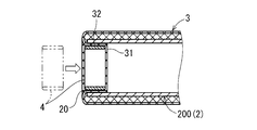
- FIG. 3 is a first longitudinal sectional view (before pipe diameter expansion processing) of the end portion of the shield pipe 2 when the electromagnetic shield component 5 is manufactured by the first method.
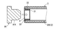
- FIG. 4 is a second vertical cross-sectional view (during pipe diameter expansion processing) of the end of the shield pipe when the electromagnetic shield component 5 is manufactured by the first method.
- FIG. 5 is a longitudinal sectional view (before the connecting member 4 is mounted) of the main part of the electromagnetic shielding component 5 when the electromagnetic shielding component 5 is manufactured by the first method.
- the shield pipe 2 can be obtained by subjecting the end portion of the pipe raw material 200 having a uniform cross-sectional shape over the entire length to a process of expanding the diameter.
- this processing is referred to as pipe diameter expansion processing.
- pipe diameter expansion processing is performed by using a molding metal fitting 9 having a diameter expansion molding surface 91 having a diameter larger than the inner peripheral surface of the pipe raw material 200. This is a process of pushing a part from the end of the pipe raw material 200 from the inside by inserting it into the opening 20 at the end of the material 200.
- the outer diameter of the enlarged diameter molding surface 91 is, for example, twice the total of the thickness of the annular connecting member 4 and the thickness of the flexible shield member 3 in the diameter of the inner peripheral surface of the pipe raw material 200. Same as or slightly larger than the combined diameter.
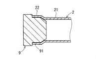
- the shield pipe 2 having the enlarged diameter portion 22 formed at the end portion is obtained by subjecting the pipe raw material 200 to the pipe diameter expansion processing.
- the inner peripheral surface of the enlarged diameter portion 22 is molded into a shape along the enlarged diameter molding surface 91 of the molding metal fitting 9.
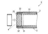
- a connecting member press-fitting step for inserting the connecting member 4 into the enlarged diameter portion 22 of the shield pipe 2 is performed. This step is performed in a state where the flexible shield member 3 is overlapped on the outer peripheral surface side of the pipe raw material 200 and a part from the end portion 31 of the flexible shield member 3 is folded back to the inside of the enlarged diameter portion 22.
- a portion of the flexible shield member 3 that is folded back to the inside of the enlarged diameter portion 22 is the overlapping portion 32.
- the outer diameter of the connecting member 4 is a diameter obtained by subtracting twice the thickness of the flexible shield member 3 from the inner diameter of the enlarged diameter portion 22. Slightly larger than.
- the connecting member 4 is, for example, a metal annular member, and does not have to have a special structure that changes and maintains its diameter.
- the connecting member press-fitting step the connecting member 4 is pushed further into the inside of the enlarged diameter portion 22 of the shield pipe 2 and the overlapping portion 32 of the flexible shield member 3 inside thereof. Thereby, the connecting member 4 is fitted inside the overlapping portion 32 while the outer diameter thereof is slightly contracted. As a result, the connecting member 4 is in a state in which the overlapping portion 32 of the flexible shield member 3 is sandwiched between the inner peripheral surface of the enlarged diameter portion 22 and fastened.
- the electric wire 1 is passed through the hollow portion of the shield pipe 2A.
- the electric wire 1 is passed through the hollow portion of the shield pipe 2A in a state where the flexible shield member 3 is overlapped on the outer peripheral surface side.
- the portion of the flexible shield member 3 that overlaps the outer peripheral surface side of the shield pipe 2A is pulled out in the extending direction of the enlarged diameter portion 22 of the shield pipe 2A. Thereby, the folding of the flexible shield member 3 is released.
- the flexible shield member 3 is pulled out as described above to cover the periphery of the portion of the electric wire 1 extending from the opening 20 of the shield pipe 2A.
- the pipe diameter expansion process is performed such that the flexible shield member 3 is overlapped on the outer peripheral surface side of the pipe raw material 200, and a part from the end portion 31 of the flexible shield member 3 is formed from the opening 20 in the pipe raw material 200. It is performed in a state in which it is folded back to the side surface and the connecting member 4 is further overlapped on the inner side.
- the pipe diameter expansion process of the second method is performed by inserting a molding fitting 9 ⁇ / b> X having a diameter expansion molding surface 91 ⁇ / b> X into the opening 20 at the end of the pipe raw material 200. 4 and a part from the end of the pipe raw material 200 are processed to spread from the inside of the connecting member 4.
- the outer diameter of the diameter-enlarged molding surface 91X is, for example, the same as or slightly larger than the inner circumferential surface of the pipe raw material 200.
- the diameter of the shield pipe 2 having the diameter-expanded portion 22 formed at the end and the overlapping portion 32 of the flexible shield member 3 with the diameter increased are increased.
- the connecting member 4 that is sandwiched between and fastened is obtained at the same time.
- the procedure after the pipe diameter increasing process in the second method is the same as the procedure after the connecting member press-fitting step in the first method (see FIG. 6).
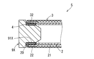
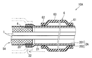
- FIG. 10 is a longitudinal sectional view of the main part of the electric wire with electromagnetic shield part 10A. 10, the same components as those shown in FIGS. 1 to 9 are given the same reference numerals.
- the electromagnetic shielding component-attached electric wire 10 ⁇ / b> A includes a shield pipe 2 ⁇ / b> A with a resin coating instead of the shielding pipe 2 and a grommet 6. The point is different.
- the difference in the electromagnetic shield component-equipped electric wire 10A from the electromagnetic shield component-equipped electric wire 10 will be described.
- the electric wire with electromagnetic shield part 10 ⁇ / b> A is also provided with the electric wire 1 and an electromagnetic shield part 5 ⁇ / b> A surrounding the electric wire 1, similarly to the electric wire with electromagnetic shield part 10.
- the electromagnetic shield component 5 ⁇ / b> A includes a shield pipe 2 ⁇ / b> A, a flexible shield member 3, and a connecting member 4.
- the shield pipe 2 ⁇ / b> A is a pipe having a metal pipe 201 and an insulating coating 202 formed on the outer peripheral surface of the metal pipe 201.
- the metal pipe 201 is a pipe mainly composed of a metal such as aluminum or stainless steel.
- the insulating coating 202 is, for example, a synthetic resin or a coating film of a rubber-based material.
- the shield pipe 2A has the same structure as the shield pipe 2 except that the insulating coating 202 is formed.
- the electric wire with electromagnetic shielding component 10A also includes a grommet 6 that is a non-conductive cylindrical elastic member.
- the grommet 6 is a member whose main component is a rubber material such as rubber or elastomer.
- the grommet 6 is a member for preventing the liquid from entering the flexible shield member 3 when the electric wire with electromagnetic shield part 10A is attached to a support body such as a vehicle body.
- the grommet 6 includes a first closing portion 61 that occupies a portion near one end thereof, a second closing portion 62 that occupies a portion near the other end, and an intermediate portion 63 therebetween.
- the first blocking portion 61 is a portion that is covered with the shield pipe 2A in close contact with the outer peripheral surface of the enlarged diameter portion 22.
- occlusion part 62 is covered with the frame part (not shown) formed around the opening which comprises the path
- the frame portion is formed, for example, around the opening of a housing that houses the device to which the electric wire 1 is connected.
- the inner peripheral surface of the first closing portion 61 has a larger diameter than the outer peripheral surface of the base portion 21 (portion adjacent to the enlarged diameter portion 22) in the shield pipe 2A and the enlarged diameter portion 22. It is formed with a smaller diameter than the outer peripheral surface.
- the natural state grommet means a grommet in a state where no external force is applied.
- the inner peripheral surface of the intermediate portion 63 connected to the first closing portion 61 is formed with a larger diameter than the outer peripheral surface of the enlarged diameter portion 22 in the shield pipe 2A.
- the entire inner peripheral surface of the grommet 6 is formed with a larger diameter than the outer peripheral surface of the base portion 21 of the shield pipe 2A.
- the electromagnetic shield component 5A When the electromagnetic shield component 5A is attached to a support such as a vehicle body, it is necessary to move the grommet 6 along the outer peripheral surface of the shield pipe 2A.
- the frictional resistance between the grommet 6 and the shield pipe 2 ⁇ / b> A is very small except when the first closing portion 61 passes through the enlarged diameter portion 22. Therefore, the grommet 6 can be moved along the shield pipe 2 ⁇ / b> A with a very small force except when the first closing portion 61 passes through the enlarged diameter portion 22.
- the grommet 6 is temporarily fastened to the shield pipe 2 ⁇ / b> A so that the entire grommet 6 surrounds the base 21 of the shield pipe 2 ⁇ / b> A, and then the first closed portion 61 is in close contact with the outer peripheral surface of the enlarged diameter portion 22. Moved to position.
- the temporary fastening state of the grommet 6 to the shield pipe 2 ⁇ / b> A may be a state in which the first closing portion 61 surrounds the base portion 21 and the intermediate portion 63 surrounds the enlarged diameter portion 22.
- the end portions of the hard shield pipes 2 and 2A containing a metal material are formed with an enlarged diameter portion 22 having a larger diameter than the adjacent base portion 21.
- the flexible shield member 3 is inserted
- a strong flexible shield member 3 containing a metal material is interposed between the electric wire 1 and the end portions of the shield pipes 2 and 2A to prevent the electric wire 1 from being damaged. For this reason, it is not necessary to cover the edges of the shield pipes 2 and 2A.
- the electromagnetic shielding components 5 and 5A are employed, even if the gap between the inner peripheral surface of the base 21 (the portion other than the enlarged diameter portion 22) of the shield pipes 2 and 2A and the outer peripheral surface of the electric wire 1 is small. In the enlarged diameter portion 22, it is possible to ensure a gap enough to insert the connecting member 4 that holds the flexible shield member 3. Therefore, even if the accommodation density of the electric wire 1 in the hollow portion of the shield pipes 2 and 2A (hard pipe) is increased, the flexible shield member 3 can be connected to the shield pipes 2 and 2A without any problem.
- the electromagnetic shielding parts 5 and 5A are employed, as shown in FIG. 6, in the step of passing the electric wire 1 through the hollow part of the electromagnetic shielding parts 5 and 5A, the electric wire 1 is inserted into the hollow part of the flexible shielding member 3 There is no need to penetrate from the end. As a result, the electric wire 1 can be easily passed through the hollow portions of the electromagnetic shielding components 5 and 5A.
- the inner peripheral surface of the connecting member 4 is formed with the same diameter or more as the inner peripheral surface of the base portion 21 of the shield pipes 2 and 2A, the enlarged diameter portion of the shield pipes 2 and 2A.
- the inner peripheral surface of the connecting member 4 inserted into 22 does not protrude inward from the extended surface of the inner peripheral surface of the base portion 21 of the shield pipes 2 and 2A. Therefore, the accommodation density of the electric wire 1 in the hollow part of the shield pipes 2 and 2A (hard pipe) can be further increased. Further, when the electric wire 1 is passed through the hollow portions of the shield pipes 2 and 2 ⁇ / b> A, the electric wire 1 is not easily caught by the connecting member 4.
- the insulating coating 202 prevents electric shock even when a high voltage is generated in the metal pipe 201.
- the flexible shield member 3 is in contact with the inner peripheral surface of the metal pipe 201 (shield pipe 2A). Therefore, the insulating coating 202 of the shield pipe 2 ⁇ / b> A does not hinder the electrical connection between the metal pipe 201 and the flexible shield member 3.
- the pipe machining process (pipe diameter machining process) for creating the enlarged diameter portion 22 of the shield pipes 2 and 2A is performed by the connecting member 4. It can also serve as an attachment process. Thereby, the manufacturing process of electromagnetic shielding components 5 and 5A can be simplified.
- the flexible shield member 3 can be fastened to the shield pipes 2 and 2A using a very simple connecting member 4.
- the grommet 6 can be moved with a very small force in the operation of moving the grommet 6 along the outer peripheral surface of the shield pipe 2A. As a result, the work of attaching the electromagnetic shielding component 5A including the grommet 6 to the support becomes easy.
- the electromagnetic shielding component and the electric wire with electromagnetic shielding component according to the present invention can be freely combined with each of the embodiments and application examples described above within the scope of the invention described in each claim, or each embodiment. Further, the present invention can be configured by appropriately modifying or omitting some of the application examples.
Abstract
The objective is to achieve, in an electromagnetic shielding component, even if the holding density of electric wires inside the hollow portion of a rigid pipe is raised, the prevention of damage to an electric wire due to contact with an edge of the pipe without requiring an additional component such as a pipe end cover. At a portion from one of the extremities, the shielding pipe has an enlarged diameter portion wherein an internal peripheral surface and an external peripheral surface have been formed with diameters that are larger than those of a continuously adjacent portion. A ring-shaped coupling member and the internal peripheral surface of the shielding pipe sandwich and fasten therebetween an overlapping portion from a flexible shielding member, which is overlapping with the enlarged diameter portion on the internal peripheral surface side thereof.
Description
本発明は、硬質のシールドパイプと柔軟シールド部材とを含む電磁シールド部品およびそれを備える電磁シールド部品付電線に関する。
The present invention relates to an electromagnetic shield component including a hard shield pipe and a flexible shield member, and an electric wire with an electromagnetic shield component including the same.
自動車などの車両に搭載されるワイヤハーネスにおいて、電線の周囲を囲む電磁シールド部品が採用される場合がある。例えば、電磁シールド部品は、硬質の金属パイプとこれに連結された筒状の編組線とを有する。
In a wire harness mounted on a vehicle such as an automobile, an electromagnetic shielding part surrounding the wire may be employed. For example, the electromagnetic shielding component has a hard metal pipe and a cylindrical braided wire connected thereto.
電磁シールド部品において、金属パイプは、電磁シールド機能を果たすとともに、電線を物理的に保護し、さらに、電線を予め定められた配線経路に沿う形状に維持する。
In the electromagnetic shielding component, the metal pipe performs an electromagnetic shielding function, physically protects the electric wire, and further maintains the electric wire in a shape along a predetermined wiring path.
一方、編組線は、銅線が編み込まれて筒状に形成された部材であるため、柔軟性を有する。柔軟性を有する編組線は、電磁シールド機能を果たすとともに、電線の末端寄りの部分の曲げ変形を可能にする。
On the other hand, since the braided wire is a member formed in a cylindrical shape by knitting copper wire, it has flexibility. The braided wire having flexibility fulfills an electromagnetic shielding function and enables bending deformation of a portion near the end of the electric wire.
特許文献1に示されるように、通常、金属パイプと編組線とは、カシメリングによって連結される。この場合、カシメリングは、金属パイプをその外周面側から締め付け、金属パイプにおける端部寄りの外周面に被さった編組線の一部を金属パイプとの間に挟み込む。これにより、編組線の端部寄りの部分が、金属パイプの端部寄りの部分の外周面側に留まる。
As shown in Patent Document 1, a metal pipe and a braided wire are usually connected by caulking. In this case, in the caulking, the metal pipe is fastened from the outer peripheral surface side, and a part of the braided wire covering the outer peripheral surface near the end of the metal pipe is sandwiched between the metal pipe. Thereby, the part near the end of the braided wire stays on the outer peripheral surface side of the part near the end of the metal pipe.
一方、特許文献2が示すシールド導電路において、編組線は、金属パイプ内に挿入された支持部材の外周面と金属パイプにおけるカシメ部(圧縮部)の内周面との間に挟み込まれる。これにより、編組線の端部寄りの部分が、金属パイプの端部寄りの部分の内周面側に留まる。
On the other hand, in the shield conductive path shown in Patent Document 2, the braided wire is sandwiched between the outer peripheral surface of the support member inserted into the metal pipe and the inner peripheral surface of the crimped portion (compressed portion) of the metal pipe. Thereby, the part near the end of the braided wire stays on the inner peripheral surface side of the part near the end of the metal pipe.
ところで、従来の一般的な電磁シールド部品においては、金属パイプの端面が、編組線の内側に存在する。この場合、金属パイプの中空部に通された電線が金属パイプの端面のエッジに接触することによる電線の損傷が懸念される。
By the way, in the conventional general electromagnetic shielding component, the end face of the metal pipe exists inside the braided wire. In this case, there is a concern that the electric wire passed through the hollow portion of the metal pipe may be damaged by contact with the edge of the end surface of the metal pipe.
そこで、一般的な電磁シールド部品は、金属パイプの端部を覆うエッジカバーを備えている。しかしながら、昨今、部品管理の工数低減の要請から、エッジカバーを用いずに電線の損傷を防止できることが望まれている。
Therefore, a general electromagnetic shielding component is provided with an edge cover that covers the end of the metal pipe. However, recently, due to the demand for reducing man-hours for parts management, it is desired that the damage of the electric wire can be prevented without using the edge cover.
一方、特許文献2が示すシールド導電路においては、編組線が、電線と金属パイプの端部との間に介在して電線の損傷を防ぐ。そのため、エッジカバーは不要である。
On the other hand, in the shield conductive path shown in Patent Document 2, the braided wire is interposed between the electric wire and the end of the metal pipe to prevent the electric wire from being damaged. Therefore, an edge cover is not necessary.
特許文献2が示すシールド導電路において、金属パイプの内周面と電線束の外周面との間に、編組線を留める支持部材を挿入できるだけの隙間が必要である。
In the shield conductive path shown in Patent Document 2, a gap is required between the inner peripheral surface of the metal pipe and the outer peripheral surface of the wire bundle so that a support member for fastening the braided wire can be inserted.
しかしながら、より細い金属パイプの採用が必要な場合、金属パイプの中空部における電線の収容密度を高めることが必要となり、金属パイプ内に支持部材を挿入できるだけの隙間を確保することが難しくなる。
However, when it is necessary to use a thinner metal pipe, it is necessary to increase the accommodation density of the electric wire in the hollow portion of the metal pipe, and it becomes difficult to secure a gap enough to insert the support member into the metal pipe.
本発明は、電磁シールド部品において、硬質のパイプの中空部における電線の収容密度を高めても、パイプ端部のカバーなどの追加部品を要することなく、パイプのエッジに接触することによる電線の損傷を防止することを目的とする。
The present invention relates to an electromagnetic shield component, and even if the housing density of the electric wire in the hollow portion of the hard pipe is increased, the electric wire is damaged due to contact with the edge of the pipe without requiring an additional component such as a cover at the end of the pipe. The purpose is to prevent.
第1態様に係る電磁シールド部品は、シールドパイプと柔軟シールド部材と連結部材とを備える。
(1)上記シールドパイプは、金属材料を含み硬質の筒状に形成された部材である。上記シールドパイプは、一端からの一部において内周面および外周面が隣に連なる部分のそれよりも大きな径で形成された拡径部を有する。
(2)上記柔軟シールド部材は、金属材料を含み柔軟な筒状に形成された部材である。上記柔軟シールド部材において、一端寄りの一部が上記シールドパイプにおける上記拡径部の内周面側に重なった重なり部を成している。上記柔軟シールド部材は、上記シールドパイプとともに一連の中空部を形成している。
(3)上記連結部材は、環状に形成され、上記柔軟シールド部材の上記重なり部を上記シールドパイプの内周面との間に挟み込んで留めている部材である。 The electromagnetic shielding component according to the first aspect includes a shield pipe, a flexible shield member, and a connecting member.
(1) The shield pipe is a member that includes a metal material and is formed in a hard cylindrical shape. The shield pipe has an enlarged diameter portion formed with a diameter larger than that of a portion where the inner peripheral surface and the outer peripheral surface are adjacent to each other in a part from one end.
(2) The flexible shield member is a member that includes a metal material and is formed in a flexible cylindrical shape. In the flexible shield member, a part near one end forms an overlapping portion overlapping the inner peripheral surface side of the enlarged diameter portion of the shield pipe. The flexible shield member forms a series of hollow portions together with the shield pipe.
(3) The connecting member is a member that is formed in an annular shape and sandwiches and holds the overlapping portion of the flexible shield member between the inner peripheral surface of the shield pipe.
第2態様に係る電磁シールド部品は、第1態様に係る電磁シールド部品の一態様である。第2態様に係る電磁シールド部品において、上記連結部材の内周面は上記シールドパイプにおける上記拡径部の隣に連なる部分の内周面と同じ径以上で形成されている。
The electromagnetic shielding component according to the second aspect is an aspect of the electromagnetic shielding component according to the first aspect. In the electromagnetic shield component according to the second aspect, the inner peripheral surface of the connecting member is formed to have the same diameter or more as the inner peripheral surface of the portion that is adjacent to the enlarged diameter portion of the shield pipe.
第3態様に係る電磁シールド部品は、第1態様または第2態様に係る電磁シールド部品の一態様である。第3態様に係る電磁シールド部品において、上記シールドパイプは、金属パイプと上記金属パイプの外周面に形成された絶縁被膜とを有する。
The electromagnetic shielding component according to the third aspect is one aspect of the electromagnetic shielding component according to the first aspect or the second aspect. In the electromagnetic shielding component according to the third aspect, the shield pipe has a metal pipe and an insulating coating formed on the outer peripheral surface of the metal pipe.
第4態様に係る電磁シールド部品は、第1態様から第3態様のいずれか1つに係る電磁シールド部品の一態様である。第4態様に係る電磁シールド部品は、非導電性の筒状の弾性部材であるグロメットをさらに備える。上記グロメットは、自然状態において、上記シールドパイプの一部の周囲を囲む一端寄りの部分の内周面が、上記シールドパイプにおける前記拡径部の隣に連なる部分の外周面よりも大きな径で、かつ、上記拡径部の外周面よりも小さな径で形成されている。
The electromagnetic shielding component according to the fourth aspect is an aspect of the electromagnetic shielding component according to any one of the first aspect to the third aspect. The electromagnetic shielding component according to the fourth aspect further includes a grommet that is a non-conductive cylindrical elastic member. In the natural state, the grommet has a larger inner peripheral surface of the portion near one end surrounding the periphery of a part of the shield pipe than the outer peripheral surface of the portion adjacent to the enlarged diameter portion in the shield pipe, And it is formed with the diameter smaller than the outer peripheral surface of the said enlarged diameter part.
第5態様に係る電磁シールド部品付電線は、電線と上記の各態様のいずれか1つに係る電磁シールド部品とを備える。この場合、筒状の電磁シールド部品は、電線の周囲を囲む。
The electric wire with an electromagnetic shielding component according to the fifth aspect includes an electric wire and an electromagnetic shielding component according to any one of the above aspects. In this case, the cylindrical electromagnetic shielding component surrounds the periphery of the electric wire.
上記の各態様において、金属材料を含む硬質のシールドパイプの端部には、隣に連なる部分よりも大きな径で形成された拡径部が形成されている。そして、柔軟シールド部材は、シールドパイプの拡径部の内側面とその内側の連結部材との間に挟み込まれている。
In each of the above embodiments, an end portion of a hard shield pipe containing a metal material is formed with an enlarged portion formed with a larger diameter than the adjacent portion. And the flexible shield member is pinched | interposed between the inner surface of the enlarged diameter part of a shield pipe, and the connection member of the inner side.
従って、上記の各態様によれば、金属材料を含む丈夫な柔軟シールド部材が、電線とシールドパイプの端部との間に介在して電線の損傷を防ぐ。そのため、シールドパイプのエッジのカバーは不要である。
Therefore, according to each aspect described above, a strong flexible shield member containing a metal material is interposed between the electric wire and the end of the shield pipe to prevent the electric wire from being damaged. Therefore, it is not necessary to cover the edge of the shield pipe.
また、上記の各態様によれば、シールドパイプにおける拡径部以外の部分の内周面と電線の外周面との間の隙間が小さくても、拡径部において、柔軟シールド部材を留める連結部材を挿入できるだけの隙間を確保することができる。そのため、シールドパイプ(硬質パイプ)の中空部における電線の収容密度を高めても、柔軟シールド部材をシールドパイプに問題なく連結できる。
Moreover, according to each aspect described above, the connecting member that holds the flexible shield member in the enlarged diameter portion even if the gap between the inner peripheral surface of the portion other than the enlarged diameter portion in the shield pipe and the outer peripheral surface of the electric wire is small. It is possible to secure a gap enough to insert the. Therefore, the flexible shield member can be connected to the shield pipe without any problem even if the accommodation density of the electric wire in the hollow portion of the shield pipe (hard pipe) is increased.
また、上記の各態様によれば、後述するように、電磁シールド部品の中空部に電線を通す工程において、柔軟シールド部材の中空部に電線をその端から貫通させる必要がない。その結果、電磁シールド部品の中空部に電線を容易に通すことが可能になる。
Moreover, according to each aspect described above, as described later, in the step of passing the electric wire through the hollow portion of the electromagnetic shielding component, it is not necessary to penetrate the electric wire from the end of the hollow portion of the flexible shield member. As a result, the electric wire can be easily passed through the hollow portion of the electromagnetic shielding component.
また、第2態様によれば、シールドパイプの拡径部内に挿入された連結部材の内周面が、シールドパイプにおける拡径部の隣に連なる部分の内周面の延長面から内側へ突出しない。そのため、シールドパイプ(硬質パイプ)の中空部における電線の収容密度をより高めることができる。また、電線がシールドパイプの中空部に通される際に、電線が連結部材に引っ掛かりにくい。
Moreover, according to the 2nd aspect, the internal peripheral surface of the connection member inserted in the enlarged diameter part of a shield pipe does not protrude inward from the extension surface of the internal peripheral surface of the part which adjoins the enlarged diameter part in a shield pipe. . Therefore, the accommodation density of the electric wire in the hollow part of a shield pipe (hard pipe) can be raised more. Further, when the electric wire is passed through the hollow portion of the shield pipe, the electric wire is not easily caught by the connecting member.
また、第3態様において、シールドパイプは、金属パイプと金属パイプの外周面に形成された絶縁被膜とを有する。絶縁被膜は、金属パイプに高電圧が生じた場合でも感電を防ぐ。また、柔軟シールド部材は、金属パイプ(シールドパイプ)の内周面に接する。そのため、シールドパイプの絶縁被膜が金属パイプと柔軟シールド部材との電気的な接続を阻害することもない。
Further, in the third aspect, the shield pipe has a metal pipe and an insulating coating formed on the outer peripheral surface of the metal pipe. The insulating coating prevents electric shock even when a high voltage is generated in the metal pipe. Further, the flexible shield member is in contact with the inner peripheral surface of the metal pipe (shield pipe). Therefore, the insulating coating of the shield pipe does not hinder the electrical connection between the metal pipe and the flexible shield member.
また、第4態様において、グロメットは、柔軟シールド部への液体の浸入を防ぐための部材であり、その一端寄りの部分はシールドパイプに対してその拡径部の外周面に密接する状態で被せられる閉塞部である。グロメットにおける閉塞部の内周面は、シールドパイプにおける拡径部の隣に連なる部分の外周面よりも大きな径で、かつ、拡径部の外周面よりも小さな径で形成されている。
In the fourth aspect, the grommet is a member for preventing liquid from entering the flexible shield part, and a portion near one end of the grommet is covered with the shield pipe in close contact with the outer peripheral surface of the enlarged diameter part. It is a closed part. The inner peripheral surface of the closing portion in the grommet is formed with a diameter larger than the outer peripheral surface of the portion adjacent to the enlarged diameter portion in the shield pipe and smaller than the outer peripheral surface of the enlarged diameter portion.
グロメットを含む電磁シールド部品が車両のボディなどの支持体に取り付けられる際、グロメットをシールドパイプの外周面に沿って移動させることが必要になる。閉塞部がシールドパイプの外周面に密接した状態のまま、摩擦係数の大きなグロメットをシールドパイプの外周面に沿って摺動させるためには、大きな力が必要である。
¡When an electromagnetic shield part including a grommet is attached to a support such as a vehicle body, it is necessary to move the grommet along the outer peripheral surface of the shield pipe. In order for the grommet having a large friction coefficient to slide along the outer peripheral surface of the shield pipe while keeping the closed portion in close contact with the outer peripheral surface of the shield pipe, a large force is required.
第4態様においては、グロメットの閉塞部は、シールドパイプの拡径部の隣に連なる部分の外周面よりも大きな径で形成されている。そのため、グロメットをシールドパイプの外周面に沿って移動させる作業において、グロメットの閉塞部がシールドパイプの拡径部を通るとき以外は、ごく小さな力でグロメットを移動させることができる。その結果、グロメットを含む電磁シールド部品を支持体に取り付ける作業が容易となる。
In the fourth aspect, the closed portion of the grommet is formed with a larger diameter than the outer peripheral surface of the portion that is adjacent to the enlarged diameter portion of the shield pipe. Therefore, in the operation of moving the grommet along the outer peripheral surface of the shield pipe, the grommet can be moved with a very small force except when the closed portion of the grommet passes through the enlarged diameter portion of the shield pipe. As a result, the work of attaching the electromagnetic shielding component including the grommet to the support becomes easy.
以下、添付の図面を参照しながら、実施形態について説明する。以下の実施形態は、本発明を具体化した一例であり、本発明の技術的範囲を限定する事例ではない。各実施形態に係る電磁シールド部品付電線は、例えば自動車などの車両に搭載されるワイヤハーネスとして提供される。
Hereinafter, embodiments will be described with reference to the accompanying drawings. The following embodiment is an example embodying the present invention, and is not an example of limiting the technical scope of the present invention. The electric wire with electromagnetic shielding components according to each embodiment is provided as a wire harness mounted on a vehicle such as an automobile.
<第1実施形態>
まず、図1,2を参照しつつ、第1実施形態に係る電磁シールド部品付電線10の構成について説明する。図1が示すように、電磁シールド部品付電線10は、電線1と電線1の周囲を囲む筒状の電磁シールド部品5とを備えている。なお、図2の断面図において、電線1については側面が示されている。図6,10の断面図においても、同様に電線1については側面が示されている。 <First Embodiment>
First, the configuration of the electromagnetic shield component-attachedelectric wire 10 according to the first embodiment will be described with reference to FIGS. As shown in FIG. 1, the electric wire 10 with an electromagnetic shielding component includes an electric wire 1 and a cylindrical electromagnetic shielding component 5 that surrounds the electric wire 1. In the cross-sectional view of FIG. 2, the side surface of the electric wire 1 is shown. 6 and 10 also show the side surfaces of the electric wire 1 in the same manner.
まず、図1,2を参照しつつ、第1実施形態に係る電磁シールド部品付電線10の構成について説明する。図1が示すように、電磁シールド部品付電線10は、電線1と電線1の周囲を囲む筒状の電磁シールド部品5とを備えている。なお、図2の断面図において、電線1については側面が示されている。図6,10の断面図においても、同様に電線1については側面が示されている。 <First Embodiment>
First, the configuration of the electromagnetic shield component-attached
<電線>
電線1は、導電性の芯線とその芯線の周囲を覆う絶縁被覆とを有する絶縁電線である。図1が示す例では、電磁シールド部品付電線10は複数の電線1を備え、電磁シールド部品5はそれら複数の電線1を囲んでいる。 <Wire>
The electric wire 1 is an insulated wire having a conductive core wire and an insulating coating covering the periphery of the core wire. In the example shown in FIG. 1, the electromagnetic shield component-equippedelectric wire 10 includes a plurality of electric wires 1, and the electromagnetic shield component 5 surrounds the plurality of electric wires 1.
電線1は、導電性の芯線とその芯線の周囲を覆う絶縁被覆とを有する絶縁電線である。図1が示す例では、電磁シールド部品付電線10は複数の電線1を備え、電磁シールド部品5はそれら複数の電線1を囲んでいる。 <Wire>
The electric wire 1 is an insulated wire having a conductive core wire and an insulating coating covering the periphery of the core wire. In the example shown in FIG. 1, the electromagnetic shield component-equipped
電磁シールド部品5は、シールドパイプ2と柔軟シールド部材3と連結部材4とを備えている。シールドパイプ2および柔軟シールド部材3は、電線1が通る一連の中空部を形成している。
The electromagnetic shield component 5 includes a shield pipe 2, a flexible shield member 3, and a connecting member 4. The shield pipe 2 and the flexible shield member 3 form a series of hollow portions through which the electric wire 1 passes.
なお、便宜上、図1,2等において、シールドパイプ2の中空部における電線1の収容密度が比較的小さい状態、即ち、シールドパイプ2の内周面と電線1の外周面との隙間が比較的大きい状態が示されている。しかしながら、各実施形態において、電線1が、図示される状態よりも高い収容密度でシールドパイプ2の中空部に収容されていることも考えられる。
For convenience, in FIGS. 1 and 2 and the like, the housing density of the electric wire 1 in the hollow portion of the shield pipe 2 is relatively small, that is, the gap between the inner peripheral surface of the shield pipe 2 and the outer peripheral surface of the electric wire 1 is relatively small. Large state is shown. However, in each embodiment, it is also conceivable that the electric wire 1 is accommodated in the hollow portion of the shield pipe 2 with a higher accommodation density than the illustrated state.
なお、電線1が、複芯のケーブルであることも考えられる。複芯のケーブルは、複数の芯線と、それら複数の芯線の相互間を絶縁するとともにそれら複数の芯線を一括して覆う絶縁被覆とを有する。
Note that the electric wire 1 may be a multi-core cable. The multi-core cable has a plurality of core wires and an insulation coating that insulates the plurality of core wires and covers the plurality of core wires together.
続いて第1実施形態に係る電磁シールド部品5について説明する。電磁シールド部品5は、シールドパイプ2と柔軟シールド部材3とが連結部材4によって連結され、これにより一連の筒状に形成された構造を有している。
Subsequently, the electromagnetic shielding component 5 according to the first embodiment will be described. The electromagnetic shield component 5 has a structure in which the shield pipe 2 and the flexible shield member 3 are connected by a connecting member 4, thereby forming a series of cylindrical shapes.
<シールドパイプ>
シールドパイプ2は、金属材料を含み硬質の筒状に形成された部材である。本実施形態では、シールドパイプ2はアルミニウムまたはステンレスなどの金属を主成分とする金属パイプである。 <Shield pipe>
Theshield pipe 2 is a member that includes a metal material and is formed in a hard cylindrical shape. In the present embodiment, the shield pipe 2 is a metal pipe whose main component is a metal such as aluminum or stainless steel.
シールドパイプ2は、金属材料を含み硬質の筒状に形成された部材である。本実施形態では、シールドパイプ2はアルミニウムまたはステンレスなどの金属を主成分とする金属パイプである。 <Shield pipe>
The
なお、シールドパイプ2が、金属パイプと金属パイプの一部に形成された非導電性の物質とが一体になった部材であることも考えられる。例えば、シールドパイプ2が、金属パイプとその金属パイプの内周面および外周面の一部に形成された絶縁被膜とを有するパイプであることなどが考えられる。
Note that it is also conceivable that the shield pipe 2 is a member in which a metal pipe and a non-conductive substance formed on a part of the metal pipe are integrated. For example, the shield pipe 2 may be a pipe having a metal pipe and an insulating coating formed on a part of the inner peripheral surface and the outer peripheral surface of the metal pipe.
シールドパイプ2は、その両端のうちの少なくとも一方からの一部を成す拡径部22とその他の部分を成す基部21とを有している。拡径部22は、シールドパイプ2Aにおける一端からの一部を成し、その内周面および外周面が隣に連なる基部21よりも大きな径で形成されている。拡径部22は、シールドパイプ2の端の開口20の枠を形成している。
The shield pipe 2 has an enlarged diameter portion 22 that forms a part from at least one of both ends thereof, and a base portion 21 that forms the other portion. The enlarged diameter portion 22 forms a part from one end of the shield pipe 2 </ b> A, and has an inner peripheral surface and an outer peripheral surface that are larger in diameter than the adjacent base portion 21. The enlarged diameter portion 22 forms a frame of the opening 20 at the end of the shield pipe 2.
拡径部22は、シールドパイプ2における一端からの一部を成し、その内周面および外周面が隣に連なる部分(基部21)よりも大きな径で形成された部分である。即ち、拡径部22の内周面の径は基部21の内周面の径よりも大きく、拡径部22の外周面の径は基部21の外周面の径よりも大きい。
The enlarged diameter portion 22 is a portion formed from one end of the shield pipe 2 and having a larger diameter than the portion (base portion 21) where the inner peripheral surface and the outer peripheral surface are adjacent to each other. That is, the diameter of the inner peripheral surface of the enlarged diameter portion 22 is larger than the diameter of the inner peripheral surface of the base portion 21, and the diameter of the outer peripheral surface of the enlarged diameter portion 22 is larger than the diameter of the outer peripheral surface of the base portion 21.
シールドパイプ2は、全長に亘って横断面形状が一様なパイプにおける端からの一部分に対して径を拡げる加工が施されることによって得られた部材である。その加工方法の一例については後述する。
The shield pipe 2 is a member obtained by applying a process for expanding the diameter to a part from the end of the pipe having a uniform cross-sectional shape over the entire length. An example of the processing method will be described later.
シールドパイプ2の基部21は、拡径部22の隣に連なる部分を含む。例えば、基部21は、横断面形状が一様な管状である。基部21は、直管状または曲がった管状である。図1が示す例では、基部21は円筒状である。なお、基部21が角パイプ状であることも考えられなくはない。
The base 21 of the shield pipe 2 includes a portion that is adjacent to the enlarged diameter portion 22. For example, the base 21 has a tubular shape with a uniform cross-sectional shape. The base 21 is a straight tube or a bent tube. In the example shown in FIG. 1, the base 21 is cylindrical. In addition, it cannot be considered that the base 21 is a square pipe shape.
例えば、シールドパイプ2の拡径部22は、シールドパイプ2の両端部各々に形成されている。
For example, the enlarged diameter portion 22 of the shield pipe 2 is formed at each end of the shield pipe 2.
<柔軟シールド部材>
柔軟シールド部材3は、金属材料を含み柔軟な筒状に形成された部材である。柔軟シールド部材3の典型例は編組線である。編組線は、導線が筒状に編み込まれた構造を有する部材である。編組線を構成する導線は、例えば、銅を主成分とする線材とその線材の表面に形成されたメッキとを含む。なお、編組線を構成する導線が、アルミニウムを主成分とする線材を含むことも考えられる。 <Flexible shield member>
Theflexible shield member 3 is a member that includes a metal material and is formed in a flexible cylindrical shape. A typical example of the flexible shield member 3 is a braided wire. The braided wire is a member having a structure in which a conducting wire is knitted into a cylindrical shape. The conducting wire constituting the braided wire includes, for example, a wire material mainly composed of copper and plating formed on the surface of the wire material. In addition, it is possible that the conducting wire which comprises a braided wire contains the wire which has aluminum as a main component.
柔軟シールド部材3は、金属材料を含み柔軟な筒状に形成された部材である。柔軟シールド部材3の典型例は編組線である。編組線は、導線が筒状に編み込まれた構造を有する部材である。編組線を構成する導線は、例えば、銅を主成分とする線材とその線材の表面に形成されたメッキとを含む。なお、編組線を構成する導線が、アルミニウムを主成分とする線材を含むことも考えられる。 <Flexible shield member>
The
なお、柔軟シールド部材3が、筒状に丸められた金属布を含む部材であることも考えられる。金属布は、金属糸の織物である。金属布は、例えば銅を主成分とする金属の糸が縦方向および横方向に交差して織られた網目構造を有する生地である。また、金属布は、金属糸の生地に樹脂材料からなる柔軟性を有するフィルムが貼り付けられた構造を有する場合もある。金属布は、導電性および柔軟性を有する。
Note that the flexible shield member 3 may be a member including a metal cloth rolled into a cylindrical shape. The metal cloth is a metal thread fabric. The metal cloth is, for example, a cloth having a network structure in which metal threads mainly composed of copper are woven so as to intersect in the longitudinal direction and the transverse direction. In addition, the metal cloth may have a structure in which a flexible film made of a resin material is attached to a metal yarn cloth. The metal cloth has conductivity and flexibility.
柔軟シールド部材3において、一方の端部31寄りの一部がシールドパイプ2における拡径部22の内周面側に被さった重なり部32を成している。これにより、柔軟シールド部材3は、シールドパイプ2とともに一連の中空部を形成している。シールドパイプ2および柔軟シールド部材3が形成する一連の中空部は、電線1の配線路である。
In the flexible shield member 3, a part near one end portion 31 forms an overlapping portion 32 that covers the inner peripheral surface side of the enlarged diameter portion 22 in the shield pipe 2. Thereby, the flexible shield member 3 forms a series of hollow portions together with the shield pipe 2. A series of hollow portions formed by the shield pipe 2 and the flexible shield member 3 are wiring paths of the electric wires 1.
<連結部材>
連結部材4は、シールドパイプ2の拡径部22と柔軟シールド部材3の重なり部32とを連結する部材であり、環状に形成されている。連結部材4は、柔軟シールド部材3の重なり部32をシールドパイプ2における拡径部22の内周面との間に挟み込んで留めている。なお、連結部材4が環状である例として、連結部材4の内周面の輪郭が楕円状または真円状である場合の他、連結部材4の内周面の輪郭が長円形(角丸長方形)である場合なども考えられる。 <Connecting member>
The connectingmember 4 is a member that connects the enlarged diameter portion 22 of the shield pipe 2 and the overlapping portion 32 of the flexible shield member 3 and is formed in an annular shape. The connecting member 4 is sandwiched between the overlapping portion 32 of the flexible shield member 3 and the inner peripheral surface of the enlarged diameter portion 22 in the shield pipe 2. As an example in which the connecting member 4 has an annular shape, the inner peripheral surface of the connecting member 4 has an oval (rounded rectangular shape) in addition to the case where the inner peripheral surface of the connecting member 4 has an elliptical shape or a perfect circular shape. ).
連結部材4は、シールドパイプ2の拡径部22と柔軟シールド部材3の重なり部32とを連結する部材であり、環状に形成されている。連結部材4は、柔軟シールド部材3の重なり部32をシールドパイプ2における拡径部22の内周面との間に挟み込んで留めている。なお、連結部材4が環状である例として、連結部材4の内周面の輪郭が楕円状または真円状である場合の他、連結部材4の内周面の輪郭が長円形(角丸長方形)である場合なども考えられる。 <Connecting member>
The connecting
連結部材4は、例えば、表面にメッキが形成された鉄を主成分とする部材、またはステンレスを主成分とする部材である。
The connecting member 4 is, for example, a member whose main component is iron whose surface is plated or a member whose main component is stainless steel.
本実施形態における連結部材4は、シールドパイプ2における拡径部22の内周面に沿う輪郭の環状に形成されている。連結部材4は、柔軟シールド部材3の重なり部32をシールドパイプ2における拡径部22の内周面との間に挟み込んでいる。例えば、連結部材4は、柔軟シールド部材3の重ね部32をシールドパイプ2の内周面に対してその全周に亘る範囲で押し付けている。
The connecting member 4 in the present embodiment is formed in an annular shape having a contour along the inner peripheral surface of the enlarged diameter portion 22 in the shield pipe 2. The connecting member 4 sandwiches the overlapping portion 32 of the flexible shield member 3 with the inner peripheral surface of the enlarged diameter portion 22 in the shield pipe 2. For example, the connecting member 4 presses the overlapping portion 32 of the flexible shield member 3 against the inner peripheral surface of the shield pipe 2 in a range over the entire circumference.
図2が示すように、連結部材4の内周面が、シールドパイプ2における拡径部22の隣に連なる基部21の内周面と同じ径以上で形成されていることが考えられる。そうすれば、連結部材4がシールドパイプ2の中空部、即ち、電線1の配線路において内側へ出っ張らない。
As shown in FIG. 2, it is conceivable that the inner peripheral surface of the connecting member 4 is formed to have the same diameter or more as the inner peripheral surface of the base portion 21 adjacent to the enlarged diameter portion 22 in the shield pipe 2. If it does so, the connection member 4 will not protrude inside in the hollow part of the shield pipe 2, ie, the wiring path of the electric wire 1. FIG.
<電磁シールド部品付電線の製造手順の一例(第1の方法)>
次に、図3~5を参照しつつ、電磁シールド部品5および電磁シールド部品付電線10の製造手順の一例(第1の方法)について説明する。 <Example of manufacturing procedure of electric wire with electromagnetic shielding component (first method)>
Next, an example (first method) of manufacturing procedures of theelectromagnetic shielding component 5 and the electric wire 10 with electromagnetic shielding component will be described with reference to FIGS.
次に、図3~5を参照しつつ、電磁シールド部品5および電磁シールド部品付電線10の製造手順の一例(第1の方法)について説明する。 <Example of manufacturing procedure of electric wire with electromagnetic shielding component (first method)>
Next, an example (first method) of manufacturing procedures of the
図3は、電磁シールド部品5が第1の方法で製造される場合におけるシールドパイプ2の端部の第1縦断面図(パイプ拡径加工前)である。図4は、電磁シールド部品5が第1の方法で製造される場合におけるシールドパイプの端部の第2縦断面図(パイプ拡径加工中)である。図5は、電磁シールド部品5が第1の方法で製造される場合における電磁シールド部品5の主要部の縦断面図(連結部材4装着前)である。
FIG. 3 is a first longitudinal sectional view (before pipe diameter expansion processing) of the end portion of the shield pipe 2 when the electromagnetic shield component 5 is manufactured by the first method. FIG. 4 is a second vertical cross-sectional view (during pipe diameter expansion processing) of the end of the shield pipe when the electromagnetic shield component 5 is manufactured by the first method. FIG. 5 is a longitudinal sectional view (before the connecting member 4 is mounted) of the main part of the electromagnetic shielding component 5 when the electromagnetic shielding component 5 is manufactured by the first method.
シールドパイプ2は、全長に亘って横断面形状が一様なパイプ原材200の端部に対してその径を拡げる加工が施されることによって得られる。以下、その加工のことをパイプ拡径加工と称する。
The shield pipe 2 can be obtained by subjecting the end portion of the pipe raw material 200 having a uniform cross-sectional shape over the entire length to a process of expanding the diameter. Hereinafter, this processing is referred to as pipe diameter expansion processing.
第1の方法において、パイプ拡径加工は、図3,4が示すように、パイプ原材200の内周面よりも大きな径の拡径成形面91が形成された成形用金具9をパイプ原材200の端の開口20に挿入することによってパイプ原材200の端からの一部を内側から押し広げる加工である。
In the first method, as shown in FIGS. 3 and 4, pipe diameter expansion processing is performed by using a molding metal fitting 9 having a diameter expansion molding surface 91 having a diameter larger than the inner peripheral surface of the pipe raw material 200. This is a process of pushing a part from the end of the pipe raw material 200 from the inside by inserting it into the opening 20 at the end of the material 200.
成形用金具9において、拡径成形面91の外径は、例えば、パイプ原材200の内周面の径に、環状の連結部材4の厚みおよび柔軟シールド部材3の厚みの合計の2倍の寸法を加算した径と同じかそれよりも若干大きい。
In the metal fitting 9 for molding, the outer diameter of the enlarged diameter molding surface 91 is, for example, twice the total of the thickness of the annular connecting member 4 and the thickness of the flexible shield member 3 in the diameter of the inner peripheral surface of the pipe raw material 200. Same as or slightly larger than the combined diameter.
パイプ拡径加工がパイプ原材200に施されることにより、端部に拡径部22が形成されたシールドパイプ2が得られる。拡径部22の内周面は、成形用金具9の拡径成形面91に沿う形状に成形される。
The shield pipe 2 having the enlarged diameter portion 22 formed at the end portion is obtained by subjecting the pipe raw material 200 to the pipe diameter expansion processing. The inner peripheral surface of the enlarged diameter portion 22 is molded into a shape along the enlarged diameter molding surface 91 of the molding metal fitting 9.
さらに、図5が示すように、連結部材4をシールドパイプ2の拡径部22内に挿入する連結部材圧入工程が行われる。本工程は、柔軟シールド部材3がパイプ原材200の外周面側に重ねられ、さらに柔軟シールド部材3における端部31からの一部が拡径部22の内側へ折り返された状態で行われる。
Furthermore, as shown in FIG. 5, a connecting member press-fitting step for inserting the connecting member 4 into the enlarged diameter portion 22 of the shield pipe 2 is performed. This step is performed in a state where the flexible shield member 3 is overlapped on the outer peripheral surface side of the pipe raw material 200 and a part from the end portion 31 of the flexible shield member 3 is folded back to the inside of the enlarged diameter portion 22.
なお、柔軟シールド部材3における拡径部22の内側へ折り返された部分が重ね部32である。
Note that a portion of the flexible shield member 3 that is folded back to the inside of the enlarged diameter portion 22 is the overlapping portion 32.
連結部材4がシールドパイプ2の拡径部22内に挿入される前の状態において、連結部材4の外径は、拡径部22の内径から柔軟シールド部材3の厚みの2倍を差し引いた径よりも若干大きい。連結部材4は、例えば金属の環状部材であり、その径を変化させて維持する特別な構造を有していなくてよい。
Before the connecting member 4 is inserted into the enlarged diameter portion 22 of the shield pipe 2, the outer diameter of the connecting member 4 is a diameter obtained by subtracting twice the thickness of the flexible shield member 3 from the inner diameter of the enlarged diameter portion 22. Slightly larger than. The connecting member 4 is, for example, a metal annular member, and does not have to have a special structure that changes and maintains its diameter.
連結部材圧入工程において、連結部材4は、シールドパイプ2の拡径部22およびその内側の柔軟シールド部材3の重ね部32のさらに内側へ押し込まれる。これにより、連結部材4は、その外径が若干収縮しつつ重ね部32の内側に嵌り込む。その結果、連結部材4は、柔軟シールド部材3の重ね部32を拡径部22の内周面との間に挟み込んで留める状態となる。
In the connecting member press-fitting step, the connecting member 4 is pushed further into the inside of the enlarged diameter portion 22 of the shield pipe 2 and the overlapping portion 32 of the flexible shield member 3 inside thereof. Thereby, the connecting member 4 is fitted inside the overlapping portion 32 while the outer diameter thereof is slightly contracted. As a result, the connecting member 4 is in a state in which the overlapping portion 32 of the flexible shield member 3 is sandwiched between the inner peripheral surface of the enlarged diameter portion 22 and fastened.
連結部材圧入工程の後、電線1が、シールドパイプ2Aの中空部に通される。例えば、図6が示すように、電線1は、柔軟シールド部材3が外周面側に重なった状態のシールドパイプ2Aの中空部に通される。この場合、柔軟シールド部材3におけるシールドパイプ2Aの外周面側に重なった部分がシールドパイプ2Aにおける拡径部22の延長方向へ引き出される。これにより、柔軟シールド部材3の折り返しは解除される。
After the connecting member press-fitting step, the electric wire 1 is passed through the hollow portion of the shield pipe 2A. For example, as FIG. 6 shows, the electric wire 1 is passed through the hollow portion of the shield pipe 2A in a state where the flexible shield member 3 is overlapped on the outer peripheral surface side. In this case, the portion of the flexible shield member 3 that overlaps the outer peripheral surface side of the shield pipe 2A is pulled out in the extending direction of the enlarged diameter portion 22 of the shield pipe 2A. Thereby, the folding of the flexible shield member 3 is released.
柔軟シールド部材3は、上記のように引き出されることにより、電線1におけるシールドパイプ2Aの開口20から延び出た部分の周囲を覆う状態となる。
The flexible shield member 3 is pulled out as described above to cover the periphery of the portion of the electric wire 1 extending from the opening 20 of the shield pipe 2A.
以上に示された手順によれば、電磁シールド部品5Aの中空部に電線1を通す工程において、柔軟シールド部材3の中空部に電線1をその端から貫通させる必要がない。
According to the procedure shown above, in the step of passing the electric wire 1 through the hollow portion of the electromagnetic shielding component 5A, it is not necessary to penetrate the hollow portion of the flexible shield member 3 from the end thereof.
なお、図6が示す手順以外の手順が採用されることも考えられる。例えば、柔軟シールド部材3が上記のように引き出された後に、電線1がシールドパイプ2およびそれに連結された柔軟シールド部材3の中空部に通されることも考えられる。
It should be noted that a procedure other than the procedure shown in FIG. 6 may be adopted. For example, it is also conceivable that after the flexible shield member 3 is pulled out as described above, the electric wire 1 is passed through the shield pipe 2 and the hollow portion of the flexible shield member 3 connected thereto.
<電磁シールド部品付電線の製造手順の一例(第2の方法)>
次に、図7~9を参照しつつ、電磁シールド部品5および電磁シールド部品付電線10の製造手順の一例(第2の方法)について説明する。 <Example of manufacturing procedure of electric wire with electromagnetic shielding component (second method)>
Next, an example (second method) of manufacturing procedures of theelectromagnetic shielding component 5 and the electric wire with electromagnetic shielding component 10 will be described with reference to FIGS.
次に、図7~9を参照しつつ、電磁シールド部品5および電磁シールド部品付電線10の製造手順の一例(第2の方法)について説明する。 <Example of manufacturing procedure of electric wire with electromagnetic shielding component (second method)>
Next, an example (second method) of manufacturing procedures of the
第2の方法において、パイプ拡径加工は、柔軟シールド部材3がパイプ原材200の外周面側に重ねられ、柔軟シールド部材3の端部31からの一部分がパイプ原材200における開口20から内側面側へ折り返され、さらに連結部材4がその内側に重ねられた状態で行われる。
In the second method, the pipe diameter expansion process is performed such that the flexible shield member 3 is overlapped on the outer peripheral surface side of the pipe raw material 200, and a part from the end portion 31 of the flexible shield member 3 is formed from the opening 20 in the pipe raw material 200. It is performed in a state in which it is folded back to the side surface and the connecting member 4 is further overlapped on the inner side.
第2の方法のパイプ拡径加工は、図8,9が示すように、拡径成形面91Xが形成された成形用金具9Xをパイプ原材200の端の開口20に挿入することによって連結部材4とパイプ原材200の端からの一部とを連結部材4の内側から押し広げる加工である。
As shown in FIGS. 8 and 9, the pipe diameter expansion process of the second method is performed by inserting a molding fitting 9 </ b> X having a diameter expansion molding surface 91 </ b> X into the opening 20 at the end of the pipe raw material 200. 4 and a part from the end of the pipe raw material 200 are processed to spread from the inside of the connecting member 4.
成形用金具9Xにおいて、拡径成形面91Xの外径は、例えば、パイプ原材200の内周面の径と同じかそれよりも若干大きい。
In the molding metal fitting 9X, the outer diameter of the diameter-enlarged molding surface 91X is, for example, the same as or slightly larger than the inner circumferential surface of the pipe raw material 200.
パイプ拡径加工がパイプ原材200に施されることにより、端部に拡径部22が形成されたシールドパイプ2と、径が拡大して柔軟シールド部材3の重ね部32を拡径部22との間に挟み込んで留める連結部材4とが同時に得られる。
By subjecting the pipe raw material 200 to pipe diameter expansion processing, the diameter of the shield pipe 2 having the diameter-expanded portion 22 formed at the end and the overlapping portion 32 of the flexible shield member 3 with the diameter increased are increased. The connecting member 4 that is sandwiched between and fastened is obtained at the same time.
第2方法におけるパイプ拡径加工の後の手順は、第1の方法における連結部材圧入工程の後の手順と同様である(図6参照)。
The procedure after the pipe diameter increasing process in the second method is the same as the procedure after the connecting member press-fitting step in the first method (see FIG. 6).
<第2実施形態>
次に、図10を参照しつつ、第2実施形態に係る電磁シールド部品付電線10Aについて説明する。図10は、電磁シールド部品付電線10Aの主要部の縦断面図である。図10において、図1~9に示される構成要素と同じ構成要素は、同じ参照符号が付されている。 Second Embodiment
Next, an electromagnetic shield component-attachedelectric wire 10A according to a second embodiment will be described with reference to FIG. FIG. 10 is a longitudinal sectional view of the main part of the electric wire with electromagnetic shield part 10A. 10, the same components as those shown in FIGS. 1 to 9 are given the same reference numerals.
次に、図10を参照しつつ、第2実施形態に係る電磁シールド部品付電線10Aについて説明する。図10は、電磁シールド部品付電線10Aの主要部の縦断面図である。図10において、図1~9に示される構成要素と同じ構成要素は、同じ参照符号が付されている。 Second Embodiment
Next, an electromagnetic shield component-attached
電磁シールド部品付電線10Aは、図1,2が示す電磁シールド部品付電線10と比較して、シールドパイプ2の代わりに樹脂被膜付のシールドパイプ2Aを備える点、およびグロメット6が追加されている点が異なる。以下、電磁シールド部品付電線10Aにおける電磁シールド部品付電線10と異なる点について説明する。
Compared with the electric wire 10 with electromagnetic shielding components shown in FIGS. 1 and 2, the electromagnetic shielding component-attached electric wire 10 </ b> A includes a shield pipe 2 </ b> A with a resin coating instead of the shielding pipe 2 and a grommet 6. The point is different. Hereinafter, the difference in the electromagnetic shield component-equipped electric wire 10A from the electromagnetic shield component-equipped electric wire 10 will be described.
電磁シールド部品付電線10Aも、電磁シールド部品付電線10と同様に、電線1とその電線1の周囲を囲む電磁シールド部品5Aとを備えている。電磁シールド部品5Aは、シールドパイプ2Aと柔軟シールド部材3と連結部材4とを備えている。
The electric wire with electromagnetic shield part 10 </ b> A is also provided with the electric wire 1 and an electromagnetic shield part 5 </ b> A surrounding the electric wire 1, similarly to the electric wire with electromagnetic shield part 10. The electromagnetic shield component 5 </ b> A includes a shield pipe 2 </ b> A, a flexible shield member 3, and a connecting member 4.
シールドパイプ2Aは、金属パイプ201とその金属パイプ201の外周面に形成された絶縁被膜202とを有するパイプである。金属パイプ201は、例えばアルミニウムまたはステンレスなどの金属を主成分とするパイプである。また、絶縁被膜202は、例えば、合成樹脂またはゴム系材料の塗装膜などである。
The shield pipe 2 </ b> A is a pipe having a metal pipe 201 and an insulating coating 202 formed on the outer peripheral surface of the metal pipe 201. The metal pipe 201 is a pipe mainly composed of a metal such as aluminum or stainless steel. Further, the insulating coating 202 is, for example, a synthetic resin or a coating film of a rubber-based material.
シールドパイプ2Aは、絶縁被膜202が形成されていること以外はシールドパイプ2と同じ構造を有している。
The shield pipe 2A has the same structure as the shield pipe 2 except that the insulating coating 202 is formed.
さらに、電磁シールド部品付電線10Aは、非導電性の筒状の弾性部材であるグロメット6も備えている。例えば、グロメット6は、ゴムまたはエラストマーなどのゴム系材料を主成分とする部材である。
Furthermore, the electric wire with electromagnetic shielding component 10A also includes a grommet 6 that is a non-conductive cylindrical elastic member. For example, the grommet 6 is a member whose main component is a rubber material such as rubber or elastomer.
グロメット6は、電磁シールド部品付電線10Aが車両のボディなどの支持体に取り付けられた際に、柔軟シールド部材3への液体の浸入を防ぐための部材である。グロメット6は、その一端寄りの部分を占める第一閉塞部61と他端寄りの部分を占める第二閉塞部62とそれらの間の中間部63とを有している。
The grommet 6 is a member for preventing the liquid from entering the flexible shield member 3 when the electric wire with electromagnetic shield part 10A is attached to a support body such as a vehicle body. The grommet 6 includes a first closing portion 61 that occupies a portion near one end thereof, a second closing portion 62 that occupies a portion near the other end, and an intermediate portion 63 therebetween.
第一閉塞部61は、シールドパイプ2Aに対してその拡径部22の外周面に密接する状態で被せられる部分である。一方、第二閉塞部62は、例えば、支持体における電線1の通路を成す開口の周囲に形成された枠部(不図示)に被せられる。その枠部は、例えば、電線1の接続先の機器を収容する筐体の開口の周囲に形成されている。
The first blocking portion 61 is a portion that is covered with the shield pipe 2A in close contact with the outer peripheral surface of the enlarged diameter portion 22. On the other hand, the 2nd obstruction | occlusion part 62 is covered with the frame part (not shown) formed around the opening which comprises the path | route of the electric wire 1 in a support body, for example. The frame portion is formed, for example, around the opening of a housing that houses the device to which the electric wire 1 is connected.
自然状態のグロメット6において、第一閉塞部61の内周面は、シールドパイプ2Aにおける基部21(拡径部22の隣に連なる部分)の外周面よりも大きな径で、かつ、拡径部22の外周面よりも小さな径で形成されている。なお、自然状態のグロメットとは、外力が加わっていない状態のグロメットを意味する。
In the grommet 6 in the natural state, the inner peripheral surface of the first closing portion 61 has a larger diameter than the outer peripheral surface of the base portion 21 (portion adjacent to the enlarged diameter portion 22) in the shield pipe 2A and the enlarged diameter portion 22. It is formed with a smaller diameter than the outer peripheral surface. The natural state grommet means a grommet in a state where no external force is applied.
また、図10が示す例では、第一閉塞部61に連なる中間部63の内周面は、シールドパイプ2Aにおける拡径部22の外周面よりも大きな径で形成されている。なお、図10が示す例では、グロメット6の内周面全体がシールドパイプ2Aの基部21の外周面よりも大きな径で形成されている。
Further, in the example shown in FIG. 10, the inner peripheral surface of the intermediate portion 63 connected to the first closing portion 61 is formed with a larger diameter than the outer peripheral surface of the enlarged diameter portion 22 in the shield pipe 2A. In the example shown in FIG. 10, the entire inner peripheral surface of the grommet 6 is formed with a larger diameter than the outer peripheral surface of the base portion 21 of the shield pipe 2A.
電磁シールド部品5Aが車両のボディなどの支持体に取り付けられる際、グロメット6をシールドパイプ2Aの外周面に沿って移動させることが必要になる。グロメット6をシールドパイプ2Aの外周面に沿って移動させる作業において、グロメット6とシールドパイプ2Aとの間の摩擦抵抗は、第一閉塞部61が拡径部22を通るとき以外はごく小さい。そのため、第一閉塞部61が拡径部22を通るとき以外はごく小さな力でグロメット6をシールドパイプ2Aに沿って移動させることができる。
When the electromagnetic shield component 5A is attached to a support such as a vehicle body, it is necessary to move the grommet 6 along the outer peripheral surface of the shield pipe 2A. In the operation of moving the grommet 6 along the outer peripheral surface of the shield pipe 2 </ b> A, the frictional resistance between the grommet 6 and the shield pipe 2 </ b> A is very small except when the first closing portion 61 passes through the enlarged diameter portion 22. Therefore, the grommet 6 can be moved along the shield pipe 2 </ b> A with a very small force except when the first closing portion 61 passes through the enlarged diameter portion 22.
図10が示す例では、グロメット6は、その全体がシールドパイプ2Aの基部21を囲む状態でシールドパイプ2Aに仮留めされ、その後、第一閉塞部61が拡径部22の外周面に密接する位置まで移動される。
In the example shown in FIG. 10, the grommet 6 is temporarily fastened to the shield pipe 2 </ b> A so that the entire grommet 6 surrounds the base 21 of the shield pipe 2 </ b> A, and then the first closed portion 61 is in close contact with the outer peripheral surface of the enlarged diameter portion 22. Moved to position.
しかしながら、シールドパイプ2Aへのグロメット6の仮留め状態が、第一閉塞部61が基部21を囲むとともに中間部63が拡径部22を囲む状態であることも考えられる。
However, the temporary fastening state of the grommet 6 to the shield pipe 2 </ b> A may be a state in which the first closing portion 61 surrounds the base portion 21 and the intermediate portion 63 surrounds the enlarged diameter portion 22.
<効果>
電磁シールド部品5,5Aにおいて、金属材料を含む硬質のシールドパイプ2,2Aの端部には、隣に連なる基部21よりも大きな径で形成された拡径部22が形成されている。そして、柔軟シールド部材3は、シールドパイプ2,2Aの拡径部22の内側面とその内側の連結部材4との間に挟み込まれている。 <Effect>
In the electromagnetic shield parts 5 and 5A, the end portions of the hard shield pipes 2 and 2A containing a metal material are formed with an enlarged diameter portion 22 having a larger diameter than the adjacent base portion 21. And the flexible shield member 3 is inserted | pinched between the inner surface of the enlarged diameter part 22 of the shield pipes 2 and 2A, and the connection member 4 of the inner side.
電磁シールド部品5,5Aにおいて、金属材料を含む硬質のシールドパイプ2,2Aの端部には、隣に連なる基部21よりも大きな径で形成された拡径部22が形成されている。そして、柔軟シールド部材3は、シールドパイプ2,2Aの拡径部22の内側面とその内側の連結部材4との間に挟み込まれている。 <Effect>
In the
電磁シールド部品5,5Aが採用されれば、金属材料を含む丈夫な柔軟シールド部材3が、電線1とシールドパイプ2,2Aの端部との間に介在して電線1の損傷を防ぐ。そのため、シールドパイプ2,2Aのエッジのカバーは不要である。
If the electromagnetic shield parts 5 and 5A are employed, a strong flexible shield member 3 containing a metal material is interposed between the electric wire 1 and the end portions of the shield pipes 2 and 2A to prevent the electric wire 1 from being damaged. For this reason, it is not necessary to cover the edges of the shield pipes 2 and 2A.
また、電磁シールド部品5,5Aが採用されれば、シールドパイプ2,2Aの基部21(拡径部22以外の部分)の内周面と電線1の外周面との間の隙間が小さくても、拡径部22において、柔軟シールド部材3を留める連結部材4を挿入できるだけの隙間を確保することができる。そのため、シールドパイプ2,2A(硬質パイプ)の中空部における電線1の収容密度を高めても、柔軟シールド部材3をシールドパイプ2,2Aに問題なく連結できる。
Moreover, if the electromagnetic shielding components 5 and 5A are employed, even if the gap between the inner peripheral surface of the base 21 (the portion other than the enlarged diameter portion 22) of the shield pipes 2 and 2A and the outer peripheral surface of the electric wire 1 is small. In the enlarged diameter portion 22, it is possible to ensure a gap enough to insert the connecting member 4 that holds the flexible shield member 3. Therefore, even if the accommodation density of the electric wire 1 in the hollow portion of the shield pipes 2 and 2A (hard pipe) is increased, the flexible shield member 3 can be connected to the shield pipes 2 and 2A without any problem.
ところで、電線1がその端から編組線などの柔軟シールド部材3の中空部に通される場合、電線1が柔軟シールド部材3に引っ掛かりやすい。
By the way, when the electric wire 1 is passed through the hollow portion of the flexible shield member 3 such as a braided wire from the end, the electric wire 1 is easily caught on the flexible shield member 3.
一方、電磁シールド部品5,5Aが採用されれば、図6が示すように、電磁シールド部品5,5Aの中空部に電線1を通す工程において、柔軟シールド部材3の中空部に電線1をその端から貫通させる必要がない。その結果、電磁シールド部品5,5Aの中空部に電線1を容易に通すことが可能になる。
On the other hand, if the electromagnetic shielding parts 5 and 5A are employed, as shown in FIG. 6, in the step of passing the electric wire 1 through the hollow part of the electromagnetic shielding parts 5 and 5A, the electric wire 1 is inserted into the hollow part of the flexible shielding member 3 There is no need to penetrate from the end. As a result, the electric wire 1 can be easily passed through the hollow portions of the electromagnetic shielding components 5 and 5A.
また、電磁シールド部品5,5Aにおいて、連結部材4の内周面がシールドパイプ2,2Aの基部21の内周面と同じ径以上で形成されていれば、シールドパイプ2,2Aの拡径部22内に挿入された連結部材4の内周面が、シールドパイプ2,2Aの基部21の内周面の延長面から内側へ突出しない。そのため、シールドパイプ2,2A(硬質パイプ)の中空部における電線1の収容密度をより高めることができる。また、電線1がシールドパイプ2,2Aの中空部に通される際に、電線1が連結部材4に引っ掛かりにくい。
Further, in the electromagnetic shield parts 5 and 5A, if the inner peripheral surface of the connecting member 4 is formed with the same diameter or more as the inner peripheral surface of the base portion 21 of the shield pipes 2 and 2A, the enlarged diameter portion of the shield pipes 2 and 2A. The inner peripheral surface of the connecting member 4 inserted into 22 does not protrude inward from the extended surface of the inner peripheral surface of the base portion 21 of the shield pipes 2 and 2A. Therefore, the accommodation density of the electric wire 1 in the hollow part of the shield pipes 2 and 2A (hard pipe) can be further increased. Further, when the electric wire 1 is passed through the hollow portions of the shield pipes 2 and 2 </ b> A, the electric wire 1 is not easily caught by the connecting member 4.
また、電磁シールド部品5Aのシールドパイプ2Aが採用されれば、絶縁被膜202が、金属パイプ201に高電圧が生じた場合でも感電を防ぐ。また、柔軟シールド部材3は、金属パイプ201(シールドパイプ2A)の内周面に接する。そのため、シールドパイプ2Aの絶縁被膜202が金属パイプ201と柔軟シールド部材3との電気的な接続を阻害することもない。
If the shield pipe 2A of the electromagnetic shield component 5A is employed, the insulating coating 202 prevents electric shock even when a high voltage is generated in the metal pipe 201. The flexible shield member 3 is in contact with the inner peripheral surface of the metal pipe 201 (shield pipe 2A). Therefore, the insulating coating 202 of the shield pipe 2 </ b> A does not hinder the electrical connection between the metal pipe 201 and the flexible shield member 3.
また、電磁シールド部品5,5Aが採用されれば、図8,9が示すように、シールドパイプ2,2Aの拡径部22を作るパイプ加工工程(パイプ拡径加工工程)が、連結部材4の取付工程を兼ねることができる。これにより電磁シールド部品5,5Aの製造工程を簡素化できる。しかも、ごくシンプルな連結部材4を用いて柔軟シールド部材3をシールドパイプ2,2Aに留めることができる。
If the electromagnetic shielding parts 5 and 5A are employed, as shown in FIGS. 8 and 9, the pipe machining process (pipe diameter machining process) for creating the enlarged diameter portion 22 of the shield pipes 2 and 2A is performed by the connecting member 4. It can also serve as an attachment process. Thereby, the manufacturing process of electromagnetic shielding components 5 and 5A can be simplified. In addition, the flexible shield member 3 can be fastened to the shield pipes 2 and 2A using a very simple connecting member 4.
また、電磁シールド部品5Aが採用されれば、グロメット6をシールドパイプ2Aの外周面に沿って移動させる作業において、ごく小さな力でグロメット6を移動させることができる。その結果、グロメット6を含む電磁シールド部品5Aを支持体に取り付ける作業が容易となる。
If the electromagnetic shielding component 5A is employed, the grommet 6 can be moved with a very small force in the operation of moving the grommet 6 along the outer peripheral surface of the shield pipe 2A. As a result, the work of attaching the electromagnetic shielding component 5A including the grommet 6 to the support becomes easy.
<応用例>
シールドパイプ2Aが電磁シールド部品5に適用されることも考えられる。また、グロメット6が電磁シールド部品5に適用されることも考えられる。 <Application example>
It is conceivable that theshield pipe 2 </ b> A is applied to the electromagnetic shield component 5. It is also conceivable that the grommet 6 is applied to the electromagnetic shield component 5.
シールドパイプ2Aが電磁シールド部品5に適用されることも考えられる。また、グロメット6が電磁シールド部品5に適用されることも考えられる。 <Application example>
It is conceivable that the
なお、本発明に係る電磁シールド部品および電磁シールド部品付電線は、各請求項に記載された発明の範囲において、以上に示された各実施形態および応用例を自由に組み合わせること、或いは各実施形態および応用例を適宜、変形するまたは一部を省略することによって構成されることも可能である。
The electromagnetic shielding component and the electric wire with electromagnetic shielding component according to the present invention can be freely combined with each of the embodiments and application examples described above within the scope of the invention described in each claim, or each embodiment. Further, the present invention can be configured by appropriately modifying or omitting some of the application examples.
10,10A 電磁シールド部品付電線
1 電線
2,2A シールドパイプ
20 シールドパイプの開口
200 パイプ原材
201 金属パイプ
202 絶縁被膜
21 シールドパイプの基部
22 シールドパイプの拡径部
3 柔軟シールド部材
31 柔軟シールド部材の端部
32 柔軟シールド部材の重ね部
4 連結部材
5,5A 電磁シールド部品
6 グロメット
61 第一閉塞部
62 第二閉塞部
63 中間部
9,9X 成形用金具
91,91X 拡径成形面 10, 10A Electric shield with electromagnetic shield part 1 Electric wire 2, 2A Shield pipe 20 Shield pipe opening 200 Pipe raw material 201 Metal pipe 202 Insulation coating
DESCRIPTION OFSYMBOLS 21 Base part of a shield pipe 22 Expanded part of a shield pipe 3 Flexible shield member 31 End part of a flexible shield member 32 Overlap part of a flexible shield member 4 Connecting member 5, 5A Electromagnetic shield part 6 Grommet 61 First closing part 62 Second closing Part 63 Intermediate part 9, 9X Molding bracket 91, 91X Expanded molding surface
1 電線
2,2A シールドパイプ
20 シールドパイプの開口
200 パイプ原材
201 金属パイプ
202 絶縁被膜
21 シールドパイプの基部
22 シールドパイプの拡径部
3 柔軟シールド部材
31 柔軟シールド部材の端部
32 柔軟シールド部材の重ね部
4 連結部材
5,5A 電磁シールド部品
6 グロメット
61 第一閉塞部
62 第二閉塞部
63 中間部
9,9X 成形用金具
91,91X 拡径成形面 10, 10A Electric shield with electromagnetic shield part 1
DESCRIPTION OF
Claims (5)
- 金属材料を含み硬質の筒状に形成され、一端からの一部において内周面および外周面が隣に連なる部分のそれよりも大きな径で形成された拡径部を有するシールドパイプと、
金属材料を含み柔軟な筒状に形成され、一端寄りの一部が前記シールドパイプにおける前記拡径部の内周面側に重なった重なり部を成し、前記シールドパイプとともに一連の中空部を形成している柔軟シールド部材と、
環状に形成され、前記柔軟シールド部材の前記重なり部を前記シールドパイプの内周面との間に挟み込んで留めている連結部材と、を備える電磁シールド部品。 A shield pipe having a diameter-enlarged portion formed with a larger diameter than that of the portion where the inner peripheral surface and the outer peripheral surface are adjacent to each other in a part from one end;
It is formed in a flexible cylindrical shape containing a metal material, and a part near one end forms an overlapping portion overlapping the inner peripheral surface side of the enlarged diameter portion in the shield pipe, and forms a series of hollow portions together with the shield pipe A flexible shield member,
An electromagnetic shield component comprising: a connecting member formed in an annular shape and sandwiching and holding the overlapping portion of the flexible shield member between the inner peripheral surface of the shield pipe. - 前記連結部材の内周面は前記シールドパイプにおける前記拡径部の隣に連なる部分の内周面と同じ径以上で形成されている、請求項1に記載の電磁シールド部品。 2. The electromagnetic shielding component according to claim 1, wherein an inner circumferential surface of the connecting member is formed to have a diameter equal to or larger than an inner circumferential surface of a portion connected to the enlarged diameter portion of the shield pipe.
- 前記シールドパイプは、金属パイプと前記金属パイプの外周面に形成された絶縁被膜とを有する、請求項1または請求項2に記載の電磁シールド部品。 The electromagnetic shield component according to claim 1 or 2, wherein the shield pipe has a metal pipe and an insulating coating formed on an outer peripheral surface of the metal pipe.
- 非導電性の筒状の弾性部材であり、自然状態において、前記シールドパイプの一部の周囲を囲む一端寄りの部分の内周面が、前記シールドパイプにおける前記拡径部の隣に連なる部分の外周面よりも大きな径で、かつ、前記拡径部の外周面よりも小さな径で形成されたグロメットをさらに備える、請求項1から請求項3のいずれか1項に記載の電磁シールド部品。 Non-conductive cylindrical elastic member, and in the natural state, the inner peripheral surface of the portion near one end surrounding the periphery of a portion of the shield pipe is a portion of the shield pipe that is adjacent to the enlarged diameter portion. The electromagnetic shielding component according to any one of claims 1 to 3, further comprising a grommet formed with a diameter larger than an outer peripheral surface and smaller than an outer peripheral surface of the enlarged diameter portion.
- 電線と、前記電線の周囲を囲む筒状の電磁シールド部品と、を備え、
前記電磁シールド部品は、
金属材料を含み硬質の筒状に形成され、一端からの一部において内周面および外周面が隣に連なる部分よりも大きな径で形成された拡径部を有するシールドパイプと、
金属材料を含み柔軟な筒状に形成され、一端寄りの一部が前記シールドパイプにおける前記拡径部の内周面側に重なった重なり部を成し、前記シールドパイプとともに前記電線が通る一連の中空部を形成している柔軟シールド部材と、
環状に形成され、前記柔軟シールド部材の前記重なり部を前記シールドパイプの内周面との間に挟み込んで留めている連結部材と、を備える電磁シールド部品付電線。 An electric wire and a cylindrical electromagnetic shielding component surrounding the electric wire;
The electromagnetic shielding component is
A shield pipe that includes a metal material and is formed in a hard cylindrical shape, and has a diameter-expanded portion formed with a larger diameter than a portion where the inner peripheral surface and the outer peripheral surface are adjacent to each other in a part from one end;
It is formed in a flexible cylindrical shape including a metal material, and a part near one end forms an overlapping portion overlapping the inner peripheral surface side of the enlarged diameter portion in the shield pipe, and a series of the electric wire passes along with the shield pipe A flexible shield member forming a hollow portion;
A connecting member that is formed in an annular shape and includes a connecting member that sandwiches and holds the overlapping portion of the flexible shield member between the inner peripheral surface of the shield pipe.
Priority Applications (3)
| Application Number | Priority Date | Filing Date | Title |
|---|---|---|---|
| DE112015000697.4T DE112015000697T5 (en) | 2014-02-06 | 2015-01-20 | Electromagnetic shielding component and electrical conduit assembly with electromagnetic shielding component |
| CN201580007082.5A CN106030726B (en) | 2014-02-06 | 2015-01-20 | Electromagnetic shielding component and the electric wire with electromagnetic shielding component |
| US15/116,906 US9743567B2 (en) | 2014-02-06 | 2015-01-20 | Electromagnetic shielding component and electric wire assembly with electromagnetic shielding component |
Applications Claiming Priority (2)
| Application Number | Priority Date | Filing Date | Title |
|---|---|---|---|
| JP2014-021146 | 2014-02-06 | ||
| JP2014021146A JP6191489B2 (en) | 2014-02-06 | 2014-02-06 | Electromagnetic shield parts and electric wires with electromagnetic shield parts |
Publications (1)
| Publication Number | Publication Date |
|---|---|
| WO2015118937A1 true WO2015118937A1 (en) | 2015-08-13 |
Family
ID=53777744
Family Applications (1)
| Application Number | Title | Priority Date | Filing Date |
|---|---|---|---|
| PCT/JP2015/051350 WO2015118937A1 (en) | 2014-02-06 | 2015-01-20 | Electromagnetic shielding component and electric wire with electromagnetic shielding component |
Country Status (5)
| Country | Link |
|---|---|
| US (1) | US9743567B2 (en) |
| JP (1) | JP6191489B2 (en) |
| CN (1) | CN106030726B (en) |
| DE (1) | DE112015000697T5 (en) |
| WO (1) | WO2015118937A1 (en) |
Cited By (3)
| Publication number | Priority date | Publication date | Assignee | Title |
|---|---|---|---|---|
| WO2017199814A1 (en) * | 2016-05-20 | 2017-11-23 | 株式会社オートネットワーク技術研究所 | Electromagnetic shield member, wiring module, and method for manufacturing electromagnetic shield member |
| WO2017204036A1 (en) * | 2016-05-25 | 2017-11-30 | 株式会社オートネットワーク技術研究所 | Electromagnetic shield member, wiring module, and method for manufacturing electromagnetic shield member |
| US20180233257A1 (en) * | 2017-02-10 | 2018-08-16 | Sumitomo Wiring Systems, Ltd. | Wire harness protection structure and method for producing braided cover-equipped wire harness |
Families Citing this family (8)
| Publication number | Priority date | Publication date | Assignee | Title |
|---|---|---|---|---|
| JP6361544B2 (en) * | 2015-03-24 | 2018-07-25 | 株式会社オートネットワーク技術研究所 | Electromagnetic shield member |
| JP2018120788A (en) * | 2017-01-26 | 2018-08-02 | 住友電装株式会社 | Wire harness and connection structure of wire harness |
| JP6816660B2 (en) * | 2017-06-15 | 2021-01-20 | 株式会社オートネットワーク技術研究所 | Manufacturing method of electromagnetic shield parts, wire harnesses and electromagnetic shield parts |
| US10147216B1 (en) * | 2017-11-01 | 2018-12-04 | Essential Products, Inc. | Intelligent camera |
| US10985538B2 (en) * | 2018-05-25 | 2021-04-20 | Leoni Bordnetz-Systeme Gmbh | System and method for reducing air volume in a splitter |
| JP7256456B2 (en) * | 2019-08-08 | 2023-04-12 | 株式会社オートネットワーク技術研究所 | wire harness |
| JP7385524B2 (en) * | 2020-04-28 | 2023-11-22 | ニデックインスツルメンツ株式会社 | motor |
| CN112930102B (en) * | 2021-01-22 | 2022-10-14 | 西安应用光学研究所 | Flexible air-tight electromagnetic shielding device |
Citations (5)
| Publication number | Priority date | Publication date | Assignee | Title |
|---|---|---|---|---|
| JP2006311699A (en) * | 2005-04-28 | 2006-11-09 | Auto Network Gijutsu Kenkyusho:Kk | Shield conductive path |
| JP2006310516A (en) * | 2005-04-28 | 2006-11-09 | Auto Network Gijutsu Kenkyusho:Kk | Shielded conductive path |
| JP2008071645A (en) * | 2006-09-14 | 2008-03-27 | Auto Network Gijutsu Kenkyusho:Kk | Conductor and its manufacturing method |
| JP2008226530A (en) * | 2007-03-09 | 2008-09-25 | Yazaki Corp | Shield pipe |
| JP2013114785A (en) * | 2011-11-25 | 2013-06-10 | Yazaki Corp | Wire harness |
Family Cites Families (17)
| Publication number | Priority date | Publication date | Assignee | Title |
|---|---|---|---|---|
| JP3409243B2 (en) * | 1998-03-10 | 2003-05-26 | 住友電装株式会社 | Grommet |
| US6545220B2 (en) * | 2001-08-31 | 2003-04-08 | Hewlett-Packard Company | Shielded cable system for high speed cable termination |
| JP4823561B2 (en) | 2005-04-28 | 2011-11-24 | 株式会社オートネットワーク技術研究所 | Shield conductive path |
| JP2007012515A (en) * | 2005-07-01 | 2007-01-18 | Auto Network Gijutsu Kenkyusho:Kk | Shield conductor |
| JP5002182B2 (en) | 2006-04-07 | 2012-08-15 | 株式会社オートネットワーク技術研究所 | Shield conductive path |
| JP2009059505A (en) * | 2007-08-30 | 2009-03-19 | Auto Network Gijutsu Kenkyusho:Kk | Shield conductor |
| US7692096B2 (en) * | 2007-12-07 | 2010-04-06 | Delphi Technologies, Inc. | Electromagnetically shielded cable |
| JP5566716B2 (en) * | 2010-02-05 | 2014-08-06 | 矢崎総業株式会社 | Wire harness |
| JP5607412B2 (en) * | 2010-04-15 | 2014-10-15 | 矢崎総業株式会社 | Wire harness |
| JP5350323B2 (en) * | 2010-06-02 | 2013-11-27 | 矢崎総業株式会社 | Braided shield member, method for manufacturing braided shield member, and wire harness |
| JP5586335B2 (en) * | 2010-06-10 | 2014-09-10 | 矢崎総業株式会社 | Shield terminal connection structure and method |
| JP5722562B2 (en) * | 2010-07-21 | 2015-05-20 | 矢崎総業株式会社 | Shield member, wire harness, and wire harness manufacturing method |
| JP2012178314A (en) * | 2011-02-28 | 2012-09-13 | Auto Network Gijutsu Kenkyusho:Kk | Shield conductor |
| JP6062812B2 (en) * | 2013-06-17 | 2017-01-18 | 矢崎総業株式会社 | Shield unit |
| JP6086323B2 (en) * | 2013-10-04 | 2017-03-01 | 住友電装株式会社 | Shield pipe |
| JP6132206B2 (en) * | 2014-03-03 | 2017-05-24 | 住友電装株式会社 | Shield conductive path |
| JP6210381B2 (en) * | 2014-08-22 | 2017-10-11 | 住友電装株式会社 | Shield conductive path |
-
2014
- 2014-02-06 JP JP2014021146A patent/JP6191489B2/en not_active Expired - Fee Related
-
2015
- 2015-01-20 US US15/116,906 patent/US9743567B2/en active Active
- 2015-01-20 DE DE112015000697.4T patent/DE112015000697T5/en not_active Withdrawn
- 2015-01-20 CN CN201580007082.5A patent/CN106030726B/en not_active Expired - Fee Related
- 2015-01-20 WO PCT/JP2015/051350 patent/WO2015118937A1/en active Application Filing
Patent Citations (5)
| Publication number | Priority date | Publication date | Assignee | Title |
|---|---|---|---|---|
| JP2006311699A (en) * | 2005-04-28 | 2006-11-09 | Auto Network Gijutsu Kenkyusho:Kk | Shield conductive path |
| JP2006310516A (en) * | 2005-04-28 | 2006-11-09 | Auto Network Gijutsu Kenkyusho:Kk | Shielded conductive path |
| JP2008071645A (en) * | 2006-09-14 | 2008-03-27 | Auto Network Gijutsu Kenkyusho:Kk | Conductor and its manufacturing method |
| JP2008226530A (en) * | 2007-03-09 | 2008-09-25 | Yazaki Corp | Shield pipe |
| JP2013114785A (en) * | 2011-11-25 | 2013-06-10 | Yazaki Corp | Wire harness |
Cited By (4)
| Publication number | Priority date | Publication date | Assignee | Title |
|---|---|---|---|---|
| WO2017199814A1 (en) * | 2016-05-20 | 2017-11-23 | 株式会社オートネットワーク技術研究所 | Electromagnetic shield member, wiring module, and method for manufacturing electromagnetic shield member |
| CN109156094A (en) * | 2016-05-20 | 2019-01-04 | 株式会社自动网络技术研究所 | The manufacturing method of electromagnetic shielding member, interconnection module and electromagnetic shielding member |
| WO2017204036A1 (en) * | 2016-05-25 | 2017-11-30 | 株式会社オートネットワーク技術研究所 | Electromagnetic shield member, wiring module, and method for manufacturing electromagnetic shield member |
| US20180233257A1 (en) * | 2017-02-10 | 2018-08-16 | Sumitomo Wiring Systems, Ltd. | Wire harness protection structure and method for producing braided cover-equipped wire harness |
Also Published As
| Publication number | Publication date |
|---|---|
| CN106030726A (en) | 2016-10-12 |
| JP2015149176A (en) | 2015-08-20 |
| JP6191489B2 (en) | 2017-09-06 |
| CN106030726B (en) | 2017-12-05 |
| DE112015000697T5 (en) | 2016-10-20 |
| US9743567B2 (en) | 2017-08-22 |
| US20170181337A1 (en) | 2017-06-22 |
Similar Documents
| Publication | Publication Date | Title |
|---|---|---|
| JP6191489B2 (en) | Electromagnetic shield parts and electric wires with electromagnetic shield parts | |
| JP5935787B2 (en) | Wire harness and wire harness manufacturing method | |
| US9718365B2 (en) | Wiring member | |
| US7491071B2 (en) | Shield end processing structure | |
| WO2015093293A1 (en) | Protection material-attached electric cable | |
| JP2003115223A (en) | Electromagnetic wave shield braid | |
| JP2012113949A (en) | Shielded conductor | |
| JP2012104727A (en) | Shield pipe, manufacturing method of shield pipe, shield pipe with cable spacer, and laying method of shield pipe with cable spacer | |
| JP6610946B2 (en) | Shield conductive path | |
| JP6156173B2 (en) | Electromagnetic shield parts | |
| CN109644583B (en) | Electromagnetic shielding member and conductive path | |
| JP2006269666A (en) | Shield structure | |
| JP2017204515A (en) | Electromagnetic shield component, wire with electromagnetic shield component, and manufacturing method of electromagnetic shield component | |
| WO2019220905A1 (en) | Wire harness | |
| JP2015065783A (en) | Wire harness | |
| CN110323635A (en) | The CA cable assembly that shape is kept | |
| JP6409672B2 (en) | Electric wire module | |
| JP6398255B2 (en) | Electromagnetic shield member | |
| WO2015159667A1 (en) | Electromagnetic shielding member and wire harness | |
| JP6229805B2 (en) | Shield conductive path | |
| JP2016062675A (en) | Wire Harness | |
| WO2016052103A1 (en) | Electromagnetic shield member | |
| JP2016072551A (en) | Electromagnetic shield member | |
| JP2016201297A (en) | Wire with connector and exterior member |
Legal Events
| Date | Code | Title | Description |
|---|---|---|---|
| 121 | Ep: the epo has been informed by wipo that ep was designated in this application |
Ref document number: 15746594 Country of ref document: EP Kind code of ref document: A1 |
|
| WWE | Wipo information: entry into national phase |
Ref document number: 15116906 Country of ref document: US |
|
| WWE | Wipo information: entry into national phase |
Ref document number: 112015000697 Country of ref document: DE |
|
| 122 | Ep: pct application non-entry in european phase |
Ref document number: 15746594 Country of ref document: EP Kind code of ref document: A1 |