JP5607412B2 - Wire harness - Google Patents
Wire harness Download PDFInfo
- Publication number
- JP5607412B2 JP5607412B2 JP2010093608A JP2010093608A JP5607412B2 JP 5607412 B2 JP5607412 B2 JP 5607412B2 JP 2010093608 A JP2010093608 A JP 2010093608A JP 2010093608 A JP2010093608 A JP 2010093608A JP 5607412 B2 JP5607412 B2 JP 5607412B2
- Authority
- JP
- Japan
- Prior art keywords
- wire
- voltage
- harness
- wires
- range
- Prior art date
- Legal status (The legal status is an assumption and is not a legal conclusion. Google has not performed a legal analysis and makes no representation as to the accuracy of the status listed.)
- Expired - Fee Related
Links
- 230000001681 protective effect Effects 0.000 claims description 6
- 230000035939 shock Effects 0.000 claims description 6
- 238000004804 winding Methods 0.000 description 8
- 239000004020 conductor Substances 0.000 description 7
- 229910052751 metal Inorganic materials 0.000 description 7
- 239000002184 metal Substances 0.000 description 7
- 239000011888 foil Substances 0.000 description 5
- 230000015572 biosynthetic process Effects 0.000 description 4
- 238000010586 diagram Methods 0.000 description 4
- 230000000694 effects Effects 0.000 description 4
- 238000004519 manufacturing process Methods 0.000 description 4
- QTBSBXVTEAMEQO-UHFFFAOYSA-M Acetate Chemical compound CC([O-])=O QTBSBXVTEAMEQO-UHFFFAOYSA-M 0.000 description 3
- 230000002159 abnormal effect Effects 0.000 description 3
- 230000006870 function Effects 0.000 description 3
- 238000000034 method Methods 0.000 description 3
- RYGMFSIKBFXOCR-UHFFFAOYSA-N Copper Chemical compound [Cu] RYGMFSIKBFXOCR-UHFFFAOYSA-N 0.000 description 2
- 229910052782 aluminium Inorganic materials 0.000 description 2
- XAGFODPZIPBFFR-UHFFFAOYSA-N aluminium Chemical compound [Al] XAGFODPZIPBFFR-UHFFFAOYSA-N 0.000 description 2
- 229910052802 copper Inorganic materials 0.000 description 2
- 239000010949 copper Substances 0.000 description 2
- 230000009993 protective function Effects 0.000 description 2
- 238000010521 absorption reaction Methods 0.000 description 1
- 239000004744 fabric Substances 0.000 description 1
- 238000009940 knitting Methods 0.000 description 1
- 238000012423 maintenance Methods 0.000 description 1
- 239000011347 resin Substances 0.000 description 1
- 229920005989 resin Polymers 0.000 description 1
Images


Classifications
-
- H—ELECTRICITY
- H02—GENERATION; CONVERSION OR DISTRIBUTION OF ELECTRIC POWER
- H02G—INSTALLATION OF ELECTRIC CABLES OR LINES, OR OF COMBINED OPTICAL AND ELECTRIC CABLES OR LINES
- H02G3/00—Installations of electric cables or lines or protective tubing therefor in or on buildings, equivalent structures or vehicles
- H02G3/02—Details
- H02G3/04—Protective tubing or conduits, e.g. cable ladders or cable troughs
- H02G3/0462—Tubings, i.e. having a closed section
- H02G3/0487—Tubings, i.e. having a closed section with a non-circular cross-section
-
- B—PERFORMING OPERATIONS; TRANSPORTING
- B60—VEHICLES IN GENERAL
- B60R—VEHICLES, VEHICLE FITTINGS, OR VEHICLE PARTS, NOT OTHERWISE PROVIDED FOR
- B60R16/00—Electric or fluid circuits specially adapted for vehicles and not otherwise provided for; Arrangement of elements of electric or fluid circuits specially adapted for vehicles and not otherwise provided for
- B60R16/02—Electric or fluid circuits specially adapted for vehicles and not otherwise provided for; Arrangement of elements of electric or fluid circuits specially adapted for vehicles and not otherwise provided for electric constitutive elements
- B60R16/0207—Wire harnesses
-
- H—ELECTRICITY
- H05—ELECTRIC TECHNIQUES NOT OTHERWISE PROVIDED FOR
- H05K—PRINTED CIRCUITS; CASINGS OR CONSTRUCTIONAL DETAILS OF ELECTRIC APPARATUS; MANUFACTURE OF ASSEMBLAGES OF ELECTRICAL COMPONENTS
- H05K9/00—Screening of apparatus or components against electric or magnetic fields
- H05K9/0073—Shielding materials
- H05K9/0098—Shielding materials for shielding electrical cables
Landscapes
- Engineering & Computer Science (AREA)
- Mechanical Engineering (AREA)
- Architecture (AREA)
- Civil Engineering (AREA)
- Structural Engineering (AREA)
- Microelectronics & Electronic Packaging (AREA)
- Details Of Indoor Wiring (AREA)
- Insulated Conductors (AREA)
- Vibration Prevention Devices (AREA)
Description
本発明は、複数本の高圧電線を含むワイヤハーネスに関する。 The present invention relates to a wire harness including a plurality of high-voltage electric wires.
電気自動車やハイブリッド自動車は、動力源となるモーターと、このモーターの駆動に必要な3相交流を発生させるインバータと、これらモーター及びインバータを接続するワイヤハーネスとを備えている。 An electric vehicle and a hybrid vehicle include a motor that is a power source, an inverter that generates a three-phase alternating current necessary for driving the motor, and a wire harness that connects the motor and the inverter.
下記特許文献1に開示されたワイヤハーネスは所謂モータケーブル装置であって、このモーターケーブル装置は、複数本の高圧電線を含むハーネス本体と、このハーネス本体の一端に設けられてモーターの接続部分となるモーター側接続部と、ハーネス本体の他端に設けられてインバータの接続部分となるインバータ側接続部と、ハーネス本体の中間に設けられてこの中間部分を車体に固定するためのハーネス固定具とを備えて構成されている。
The wire harness disclosed in the following
ハーネス固定具は、専用の取付台及び固定金具を用いて車体に固定されるようになっている。ハーネス固定具や専用の取付台及び固定金具は、車体に対する固定部分であって、これらは車両に生じる振動や衝撃に起因したハーネス本体の振れを規制するために備えられている。 The harness fixture is fixed to the vehicle body using a dedicated mounting base and fixture. A harness fixture, a dedicated mounting base, and a fixture are fixing portions for the vehicle body, and are provided for restricting the vibration of the harness body caused by vibrations and impacts generated in the vehicle.
上記従来技術にあっては、次のような問題点を有している。すなわち、モーターは動力源であるとともに振動発生源でもあることから、発生した振動がハーネス本体を介して固定部分にまで伝わり、仮に固定部分において構造上のガタ等が大きい場合には、固定部分での異音や破損等を引き起こしてしまうという問題点を有している。 The above prior art has the following problems. In other words, since the motor is a power source as well as a vibration source, the generated vibration is transmitted to the fixed part via the harness body. It has the problem of causing abnormal noise and damage.
そこで本願発明者は、モーターからの振動や車両に生じる振動及び衝撃をケーブル本体に積極的に伝え、これによりケーブル本体を振らせ、そして、この振れにより振動等を吸収して上記問題点を解消することを考えている。 Therefore, the inventor of the present application positively transmits the vibration from the motor and the vibration and impact generated in the vehicle to the cable main body, thereby causing the cable main body to be shaken, and this vibration absorbs vibration and the like to solve the above problems. I'm thinking about doing that.
本発明は、上記した事情に鑑みてなされたもので、ケーブル本体を有効に振らせることが可能なワイヤハーネスを提供することを課題とする。 This invention is made | formed in view of an above-described situation, and makes it a subject to provide the wire harness which can shake a cable main body effectively.
上記課題を解決するためになされた請求項1記載の本発明のワイヤハーネスは、複数本の高圧電線からなるハーネス本体を備え、車両走行時に生じる振動の発生源となる機器に一端が接続される車両用のワイヤハーネスにおいて、
前記ハーネス本体は、前記機器に接続される端末部と,該端末部に連続する中間部と,からなり、
前記中間部には、
前記振動の発生源となる機器を駆動させたときに生じる振動又は外部からの物理的衝撃を前記複数本の高圧電線に伝達して該複数本の高圧電線の振れを許容する範囲を設け、
前記振れを許容する範囲には、
前記振動の発生源となる機器側に配置され、隣り合う前記高圧電線同士が互いに接触しないように所定の間隔をあけて配索してなる電線・個別振れ範囲を設け、
前記複数本の高圧電線は、
前記電線・個別振れ範囲においては、前記振動又は前記物理的衝撃が伝達されたときに、それぞれの高圧電線が互いに自由な方向に振れ可能となるように配索したことを特徴とする。
The wire harness of the present invention according to
The harness body includes a terminal part connected to the device, and an intermediate part continuous to the terminal part,
In the intermediate part,
The range that allows to transmit the physical impact from the vibration or external occurs when to drive the device as a source of the vibration to the high-voltage wire of the plurality of deflection of the high-voltage wire of the plurality of provided,
The range that allows the shake is as follows:
Provided on the device side that is the generation source of the vibration, provided an electric wire and individual run-out range that is arranged with a predetermined interval so that the adjacent high-voltage electric wires do not contact each other,
The plurality of high-voltage wires are
In the electric wire / individual shake range , the high-voltage electric wires are routed so as to be able to swing in free directions when the vibration or the physical shock is transmitted .
このような特徴を有する本発明によれば、外部からの振動や衝撃(例えばモーターからの振動や車両に生じる振動及び衝撃)をハーネス本体の中間における複数本の高圧電線に積極的に伝えて高圧電線を振らせ、そして、この振れにより振動等の吸収を可能にする。高圧電線は比較的腰のある電線であるが、高圧電線を個別に振らせることが可能に配線することで、振動等は有効に吸収される。 According to the present invention having such characteristics, external vibrations and shocks (for example, vibrations from motors and vibrations and shocks generated in vehicles) are actively transmitted to a plurality of high-voltage wires in the middle of the harness body. The electric wire is shaken, and vibration can be absorbed by this shake. Although the high-voltage electric wire is a relatively loose electric wire, vibrations and the like are effectively absorbed by wiring the high-voltage electric wires so that they can be individually swung.
請求項2記載の本発明のワイヤハーネスは、請求項1に記載のワイヤハーネスにおいて、前記複数本の高圧電線として複数本のシールド電線を用いることを特徴とする。 A wire harness according to a second aspect of the present invention is the wire harness according to the first aspect, wherein a plurality of shielded electric wires are used as the plurality of high-voltage electric wires.
このような特徴を有する本発明によれば、複数本のシールド電線を含むハーネス本体になる。シールド電線は、電線自体の構成にシールド部材を含むことから、ワイヤハーネスとして少ない構成で電磁シールド対策を施すことが可能になる。 According to the present invention having such characteristics, a harness body including a plurality of shielded electric wires is obtained. Since the shielded wire includes a shield member in the configuration of the wire itself, it is possible to take electromagnetic shielding measures with a small configuration as a wire harness.
請求項3記載の本発明のワイヤハーネスは、請求項1に記載のワイヤハーネスにおいて、前記複数本の高圧電線として複数本の非シールド電線を用いる一方、前記ハーネス本体として前記複数本の非シールド電線を一括して覆うシールド部材を含むことを特徴とする。 A wire harness according to a third aspect of the present invention is the wire harness according to the first aspect, wherein a plurality of unshielded electric wires are used as the plurality of high voltage electric wires, while the plurality of unshielded electric wires are used as the harness body. Including a shield member that collectively covers the.
このような特徴を有する本発明によれば、非シールド電線を用いることで、電線自体の構成を簡素化することが可能になる。本発明におけるハーネス本体は、複数本の非シールド電線と、これを一括して覆うシールド部材とを含む構成になる。 According to the present invention having such features, the configuration of the electric wire itself can be simplified by using the unshielded electric wire. The harness main body in the present invention includes a plurality of non-shielded electric wires and a shield member that collectively covers them.
請求項4記載の本発明のワイヤハーネスは、請求項1ないし請求項3いずれか記載のワイヤハーネスにおいて、 前記ハーネス本体は前記個別に振れ可能な状態を保ちつつ前記複数本の高圧電線を覆う保護部材を含むことを特徴とする。 The wire harness according to a fourth aspect of the present invention is the wire harness according to any one of the first to third aspects, wherein the harness body covers the plurality of high-voltage wires while maintaining the individually swingable state. It is characterized by including a member.
このような特徴を有する本発明によれば、高圧電線を個別に振らせる範囲において、保護部材は恰も「ブカブカ」の状態で複数本の高圧電線を覆う。保護部材は、個別の振れに対して影響を来さないように保護機能を発揮する。 According to the present invention having such a feature, the protection member covers a plurality of high-voltage wires in a state of being “buzzy” within a range in which the high-voltage wires are individually shaken. The protective member exhibits a protective function so as not to affect individual vibrations.
請求項1に記載された本発明によれば、外部からの振動や衝撃を積極的にハーネス本体の中間に伝えることから、また、複数本の高圧電線を個別に振らせることが可能であることから、有効に振動等の吸収をすることができるという効果を奏する。本発明のように、振動等の吸収をすることができれば、異音や破損等の発生も防止することができるという効果を奏する。本発明によれば、ケーブル本体を有効に振らせることが可能なワイヤハーネスを提供することができるという効果を奏する。 According to the first aspect of the present invention, since vibrations and impacts from the outside are actively transmitted to the middle of the harness body, it is possible to swing a plurality of high-voltage wires individually. Therefore, there is an effect that vibration and the like can be effectively absorbed. If the vibration can be absorbed as in the present invention, it is possible to prevent the occurrence of abnormal noise or breakage. According to the present invention, it is possible to provide a wire harness capable of effectively swinging a cable body.
請求項2、3に記載されたそれぞれの本発明によれば、ハーネス本体としてのより良い一例を提供することができるという効果を奏する。
According to each of the present inventions described in
請求項4に記載された本発明によれば、保護部材にて複数本の高圧電線を保護することができるという効果を奏する。
According to the present invention described in
ワイヤハーネスは、複数本の高圧電線を含むハーネス本体を備え、ハーネス本体の中間は複数本の高圧電線の振れを許容する範囲を有する。この範囲では、複数本の高圧電線を個別に振れ可能とするように配線をする。 The wire harness includes a harness main body including a plurality of high-voltage electric wires, and the middle of the harness main body has a range that allows the plurality of high-voltage electric wires to swing. In this range, wiring is performed so that a plurality of high-voltage electric wires can swing individually.
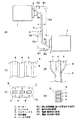
以下、図面を参照しながら実施例を説明する。図1は本発明のワイヤハーネスを示す図である。また、図2は高圧電線の状態に係る図、図3はハーネス本体の構成に係る図、図4はワイヤハーネスの製造に係る図である。 Hereinafter, embodiments will be described with reference to the drawings. FIG. 1 is a view showing a wire harness of the present invention. Moreover, FIG. 2 is a figure which concerns on the state of a high voltage electric wire, FIG. 3 is a figure which concerns on the structure of a harness main body, FIG. 4 is a figure which concerns on manufacture of a wire harness.
本実施例のワイヤハーネスは、特に限定するものでないが、ハイブリッド自動車又は電気自動車に配索されるものを対象にしている。具体的には、高圧用のものであって、モーターとインバータとを繋ぐように配索されるワイヤハーネスや、インバータとバッテリーとを繋ぐように配索されるワイヤハーネス、或いは機器間(例えば電気接続箱などの機器を含む)を繋ぐように配索されるワイヤハーネスを対象にしている。以下では、モーターとインバータとを繋ぐワイヤハーネスを例を挙げて説明をする。 Although the wire harness of a present Example is not specifically limited, It is intended for what is wired to a hybrid vehicle or an electric vehicle. Specifically, it is for high voltage, and is wired to connect the motor and the inverter, wired to connect the inverter and the battery, or between devices (for example, electric (Including devices such as connection boxes). Below, the wire harness which connects a motor and an inverter is mentioned as an example, and is demonstrated.
図1において、電気自動車やハイブリッド自動車におけるモーター1及びインバータ2は、ワイヤハーネス3(モーターケーブルともいう)により電気的に接続されている。ワイヤハーネス3は、複数本の高圧電線4を含むハーネス本体5と、ハーネス本体5の一端(端末部)に設けられるモーター側接続部6と、ハーネス本体5の他端(端末部)に設けられるインバータ側接続部7とを含んで構成されている。
In FIG. 1, a
ワイヤハーネス3は、ハーネス本体5における複数本の高圧電線4の所定範囲に、モーター1からの振動や車両からの衝撃等を積極的に伝え、これにより図中矢印方向に振れを生じさせることができるようになっている。そして、この振れにより振動等を吸収することができるようになっている。ワイヤハーネス3は、上記のような振動吸収構造を有するように構成されている。以下、ワイヤハーネス3の各構成について説明をする。
The
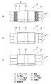
図1及び図2において、上記ハーネス本体5は、複数本の高圧電線4と、これらを一括して覆う保護部材8とを含んで構成されている。複数本の高圧電線4には、モーター1からの振動や衝撃を積極的に伝えて振れが生じるようにする振れ許容範囲R1を有している。振れ許容範囲R1は、ハーネス本体5の中間における複数本の高圧電線4の振れを許容する範囲として設定されている。振れ許容範囲R1は、本実施例においてハーネス本体5の中間5aの全部が該当するようになっている。すなわち、本実施例においては、ハーネス本体5の両方の端末部5bを除く範囲が振れ許容範囲R1として設定されている。尚、ハーネス本体5の中間5aに固定点(例えば特許文献1のハーネス固定具など)を設けるような場合には、この固定点の振動発生源側に振れ許容範囲R1が設定されるものとする。
1 and 2, the
本実施例において、振れ許容範囲R1の両側は、端末部5bの形成範囲に対応する端末部形成範囲R2として設定されている。また、振れ許容範囲R1においては、電線・個別振れ範囲R3と電線・束状振れ範囲R4とで構成されるように設定されている(この構成に限らず、電線・個別振れ範囲R3のみであってもよいものとする)。電線・個別振れ範囲R3と電線・束状振れ範囲R4は連続しており、電線・個別振れ範囲R3が振動発生源側に配置されている。これら電線・個別振れ範囲R3及び電線・束状振れ範囲R4の詳細に関しては後述する。
In the present embodiment, both sides of the allowable shake range R1 are set as the terminal portion formation range R2 corresponding to the formation range of the
高圧電線4は、高圧用の電線(高圧ケーブル)であって、本実施例では3本用いられている。3本の高圧電線4は、全て同じものが用いられている。高圧電線4は、導体部と、この導体部を被覆する被覆部とを含んで構成されている。導体部は、特に限定するものでないが、銅やアルミニウムからなる撚り線導体にて形成されている。或いは、同じく銅やアルミニウムからなる平角導体や丸導体にて形成されている。尚、図中においては、平角導体を含む高圧電線4として示されている(一例であるものとする)。本実施例における高圧電線4は、非シールド電線の構成になっている(シールド電線の構成にする場合については後述する)。
The high-
高圧電線4は、モーター1及びインバータ2の距離に相当する長さと、図1矢印方向の振れに必要な長さとを合計した長さにて形成されている。言い換えれば、本実施例の場合、振れ許容範囲R1と端末部形成範囲R2とに対応する長さを少なくとも確保して形成されている。
The high-voltage
振れ許容範囲R1における電線・個別振れ範囲R3において、複数本の高圧電線4は、各高圧電線4が個別に振れ可能となるような状態に配線されている。具体的な一例としては、隣り合う高圧電線4同士が所定の間隔をあけて個別に振れ可能となるような状態に配線されている。尚、個別に振れ可能であれば、上記所定の間隔をあけることは任意であるものとする。
In the electric wire / individual shake range R3 in the shake allowable range R1, the plurality of high-
振れ許容範囲R1における電線・束状振れ範囲R4において、高圧電線4同士は、これらが接し合いの状態になるように配線されている。もう少し具体的に説明すると、電線・個別振れ範囲R3と電線・束状振れ範囲R4との境界あたりでは、個別に振れ可能な状態である複数本の高圧電線4の間隔が次第に狭まり、これにより接し合いの状態になるようになっている。接し合いの状態は、高圧電線4同士を図2(a)に示す如く上下に重ねたり、図2(b)に示す如く横に並べたりすることにより形成されている。高圧電線4同士を接し合いの状態にすると、細くなり、配索スペース面での配慮をすることができるという利点を有している。高圧電線4同士を接し合いの状態にすると、束状になるようになっている。
In the electric wire / bundle runout range R4 in the runout allowable range R1, the high-
引用符号Tで示す電線・個別振れ範囲R3と電線・束状振れ範囲R4との境界部分は、図中の場合、高さ方向が狭くなるようになっている(低背化されている)。また、引用符号Wで示す上下に重なる部分は、幅方向が狭くなるようになっている(狭小化されている)。 The boundary portion between the electric wire / individual run-out range R3 and the electric wire / bundle run-out range R4 indicated by the reference sign T is narrowed in the height direction in the drawing (lowered). In addition, a portion overlapping the upper and lower sides indicated by the reference sign W is narrowed (narrowed) in the width direction.
尚、接し合いの状態を維持するためには、図2(c)に示す如くの整列維持部材9を用いてもよいものとする。整列維持部材9は、例えば樹脂製であって、略U字状に形成されている。整列維持部材9は、この内側に高圧電線4を挿入すると、接し合いの状態や整列状態を維持したまま保持をすることができるように形成されている。
In order to maintain the contact state, an alignment maintaining member 9 as shown in FIG. 2C may be used. The alignment maintaining member 9 is made of resin, for example, and is formed in a substantially U shape. The alignment maintaining member 9 is formed such that when the high voltage
図1、図2、及び図3(a)において、保護部材8は、上記の如く複数本の高圧電線4を一括して覆う部材であって、高圧電線4が本実施例では非シールド電線であることから、電線保護機能と電磁シールド機能とを発揮することができるように構成されている。
1, 2, and 3 (a), the
保護部材8の構成に関して図3(a)を参照しながら具体的に説明をすると、保護部材8は、シールド部材としての機能を有する編組10と、この編組10の外側に設けられる外装部材11と、外装部材11のバラケを防止するテープ巻き12とを含んで構成されている。このような構成の保護部材8は、図1(b)〜(e)、及び図2(a)に示す如く設けられている。具体的には、振れ許容範囲R1における電線・個別振れ範囲R3において、個別に振れ可能な状態を保ちつつ複数本の高圧電線4を覆うように、言い換えれば複数本の高圧電線4を「ブカブカ」に覆うように設けられている。また、電線・束状振れ範囲R4においては、束状になった複数本の高圧電線4に対し「きっちりと付く」ように設けられている。尚、「きっちりと付く」ように設けるには、テープ巻き12をきつく巻くことや密に巻くことが有効である。
The configuration of the
電線個別振れ範囲R3に対応する保護部材8の内部空間13(図1(c)参照)においては、矢印に示す如く高圧電線4が個別に振れる(自由に振れる)ことができるような状態になっている。
In the internal space 13 (see FIG. 1C) of the
編組10は、導電性を有する極細の素線を筒状に編んで形成されている。編組10の内側には、複数本の高圧電線4が一括して挿通されるようになっている。編組10は、電線・個別振れ範囲R3に対応する部分が径方向に引き伸ばされ、電線・束状振れ範囲R4に対応する部分は高圧電線4に対し密着する(外装部材11を設けた時に密着するような状態になればよい)ような使用形態、或いは上記引き伸ばしをする必要のないサイズのものが用いられ、電線・束状振れ範囲R4に対応する部分は窄められて高圧電線4に対し密着するような使用形態になっている。尚、編組10は上記に限らず、シート状のものを巻いて筒状に形成してもよいものとする。
The
外装部材11は、外部に対して保護機能を発揮させる部材として設けられている。外装部材11は、本実施例において耐摩耗性があり柔軟性を有するシート状のものが用いられている。外装部材11は、編組10の外側に巻き付けられるようになっている。外装部材11としては、例えばツイストチューブが一例として挙げられるものとし、所定の位置でテープ巻き12が施されるようになっている。外装部材11は、この全長が編組10よりも若干短く、このため編組10が露出するようになっている。編組10が露出する境界部分は、例えばアセテートクロスからなるテープが巻き付けられてアセテートチューブ(図示省略)が形成されている。
The
保護部材8に関し、編組10の替わりに金属箔14(図3(b)参照)を用い、この金属箔14の外側に外装部材11を巻き付けるようにしてもよいものとする。また、高圧電線4が非シールド電線でなくシールド電線4′の場合には、編組10や金属箔14を設けずに外装部材11を直接高圧電線4に巻き付けるようにしてもよいものとする(図3(c)参照)。
Regarding the
保護部材8は、モーター側接続部6及びインバータ側接続部7(図1(a)参照)に跨るような長さに形成されている。
The
モーター側接続部6は、高圧電線4の各端末に設けられる端子金具(図示省略)と、この端子金具を各々収容固定するための絶縁性のハウジング(図示省略)と、モーター1側でアースされるアース部(図示省略)と、編組10の一端をアース部に接続固定するための金属シェル(図示省略)とを備えて構成されている。モーター側接続部6は、公知の構造が採用されている(公知の構造であることから、ここでの詳細な説明は省略するものとする)。
The motor-
インバータ側接続部7は、上記モーター側接続部6と同じに構成されている。すなわち、インバータ側接続部7は、高圧電線4の各端末に設けられる端子金具(図示省略)と、この端子金具を各々収容固定するための絶縁性のハウジング(図示省略)と、インバータ2側でアースされるアース部(図示省略)と、編組10の他端をアース部に接続固定するための金属シェル(図示省略)とを備えて構成されている。インバータ側接続部7は、公知の構造が採用されている(公知の構造であることから、ここでの詳細な説明は省略するものとする)。
The inverter
モーター側接続部6及びインバータ側接続部7は、ワイヤハーネス3における接続部として設けられており、ワイヤハーネス3の使用形態(配索)に応じて構成等が変わるものとする。
The motor
次に、上記構成及び構造に基づき、ワイヤハーネス3の製造について説明をする。
Next, the manufacture of the
図4において、ワイヤハーネス3は、複数本の高圧電線4に振れ許容範囲R1を設定するとともに、この振れ許容範囲R1に電線・個別振れ範囲R3と電線・束状振れ範囲R4とを設定してなるものであり、図4(a)に示す如く電線・個別振れ範囲R3を設定する範囲では、個別に振れ可能な状態を形成するためとして、例えば高圧電線4同士の間にダミーの電線15を介在させる作業を先ず行う(ダミーの電線15に限らず、単なる棒であってもよいものとする。本実施例においては、高圧電線4同士の間をあけるようにしてダミーの電線15を設けているが、個別に振れ可能な状態を形成できればよいことから、単なる棒を1本抱き合わせるようにすることでも有効であるものとする)。一方、電線・束状振れ範囲R4を設定する範囲では、高圧電線4同士を接し合いの状態にする作業を行う。
In FIG. 4, the
次に、ダミーの電線15を介在させた状態の複数本の高圧電線4に編組10(図3(a)参照)を挿通する作業を行う(編組10に対し挿通するようにしてもよいものとする)。
Next, an operation of inserting the braid 10 (see FIG. 3A) through the plurality of high-voltage
続いて、編組10の外側にシート状の外装部材11を巻き付けるとともに、所望の位置にテープ巻き12を施す作業を行う。外装部材11の巻き付けは、電線・個別振れ範囲R3において、個別に振れ可能な状態を保つように、言い換えれば「ブカブカ」の状態を保つように行われる。また、電線・束状振れ範囲R4においては、「きっちりと付く」ように行われる。
Subsequently, the sheet-shaped
続いて、図4(b)及び(c)に示す如くダミーの電線15を引き抜く作業を行う。ダミーの電線15を完全に引き抜くと、複数本の高圧電線4は個別に振れ可能な状態になる。
Subsequently, as shown in FIGS. 4B and 4C, an operation of pulling out the dummy
続いて、特に図示しないが、各高圧電線4の端末にモーター側接続部6やインバータ側接続部7を設ける作業を行う。また、編組10の端部をアース部に接続固定する作業や、上記アセテートチューブ(図示省略)を形成する作業を行う。以上によりワイヤハーネス3の製造が完了する。
Subsequently, although not particularly illustrated, an operation of providing the motor
続いて、上記構成及び構造に基づき、ワイヤハーネス3の作用について説明をする。
Then, based on the said structure and structure, the effect | action of the
図1(a)において、モーター1とインバータ2とをワイヤハーネス3により電気的に接続し、この接続状態でモーター1を駆動させたり車両を走行させたりすると、ワイヤハーネス3にはモーター1又は外部からの振動や衝撃が伝わり、これによって振れ許容範囲R1に対応する部分(特に電線・個別振れ範囲R3)に矢印方向の振れが生じる。この振れは上記振動等の吸収に寄与する。従って、上記の振れが生じても、インバータ側接続部7に影響を与えるような振れの力が加わることはない。
In FIG. 1A, when the
以上、図1ないし図4を参照しながら説明してきたように、本発明のワイヤハーネス3によれば、ハーネス本体5における複数本の高圧電線4に設定した振れ許容範囲R1(電線・個別振れ範囲R3と電線・束状振れ範囲R4)に対し、モーター1等からの振動や衝撃を積極的に伝えることから、振動等の吸収を図ることができる。本発明のワイヤハーネス3のように、振動等の吸収をすることができれば、異音や破損等の発生も防止することができる。また、本発明のワイヤハーネス3によれば、電線・個別振れ範囲R3における複数本の高圧電線4を個別に振れ可能な状態に配線することから、高圧電線4を有効に振らせることができる。
As described above with reference to FIGS. 1 to 4, according to the
この他、本発明のワイヤハーネス3によれば、特に電線・束状振れ範囲R4において低背化を図ることが可能であることから、配索スペースの面において配慮することができる。
In addition, according to the
本発明は本発明の主旨を変えない範囲で種々変更実施可能なことは勿論である。 It goes without saying that the present invention can be variously modified without departing from the spirit of the present invention.
1…モーター
2…インバータ
3…ワイヤハーネス
4…高圧電線
4′…シールド電線
5…ハーネス本体
5a…中間
5b…端末部
6…モーター側接続部
7…インバータ側接続部
8…保護部材
9…整列維持部材
10…編組(シールド部材)
11…外装部材
12…テープ巻き
13…内部空間
14…金属箔
15…ダミーの電線
R1…振れ許容範囲(振れを許容する範囲)
R2…端末部形成範囲
R3…電線・個別振れ範囲
R4…電線・束状振れ範囲
DESCRIPTION OF
DESCRIPTION OF
R2 ... Terminal part formation range R3 ... Wire / individual runout range R4 ... Wire / bundle runout range
Claims (4)
前記ハーネス本体は、前記機器に接続される端末部と,該端末部に連続する中間部と,からなり、
前記中間部には、
前記振動の発生源となる機器を駆動させたときに生じる振動又は外部からの物理的衝撃を前記複数本の高圧電線に伝達して該複数本の高圧電線の振れを許容する範囲を設け、
前記振れを許容する範囲には、
前記振動の発生源となる機器側に配置され、隣り合う前記高圧電線同士が互いに接触しないように所定の間隔をあけて配索してなる電線・個別振れ範囲を設け、
前記複数本の高圧電線は、
前記電線・個別振れ範囲においては、前記振動又は前記物理的衝撃が伝達されたときに、それぞれの高圧電線が互いに自由な方向に振れ可能となるように配索した
ことを特徴とするワイヤハーネス。 In a vehicle wiring harness comprising a harness body composed of a plurality of high-voltage electric wires , one end of which is connected to a device that is a source of vibration generated during vehicle travel ,
The harness body includes a terminal part connected to the device, and an intermediate part continuous to the terminal part,
In the intermediate part,
The range that allows to transmit the physical impact from the vibration or external occurs when to drive the device as a source of the vibration to the high-voltage wire of the plurality of deflection of the high-voltage wire of the plurality of provided,
The range that allows the shake is as follows:
Provided on the device side that is the generation source of the vibration, provided an electric wire and individual run-out range that is arranged with a predetermined interval so that the adjacent high-voltage electric wires do not contact each other,
The plurality of high-voltage wires are
In the electric wire / individual vibration range , the high-voltage electric wires are routed so that they can be swung in free directions when the vibration or the physical shock is transmitted .
前記複数本の高圧電線として複数本のシールド電線を用いる
ことを特徴とするワイヤハーネス。 The wire harness according to claim 1,
A wire harness, wherein a plurality of shielded wires are used as the plurality of high-voltage wires.
前記複数本の高圧電線として複数本の非シールド電線を用いる一方、前記ハーネス本体として前記複数本の非シールド電線を一括して覆うシールド部材を含む
ことを特徴とするワイヤハーネス。 The wire harness according to claim 1,
A wire harness comprising: a shield member that collectively covers the plurality of non-shielded wires as the harness body while using the plurality of unshielded wires as the plurality of high-voltage wires.
前記ハーネス本体は前記個別に振れ可能な状態を保ちつつ前記複数本の高圧電線を覆う保護部材を含む
ことを特徴とするワイヤハーネス。 In the wire harness in any one of Claims 1 thru | or 3,
The harness body includes a protective member that covers the plurality of high-voltage electric wires while maintaining the individually swingable state.
Priority Applications (5)
| Application Number | Priority Date | Filing Date | Title |
|---|---|---|---|
| JP2010093608A JP5607412B2 (en) | 2010-04-15 | 2010-04-15 | Wire harness |
| CN201180018978.5A CN102859819B (en) | 2010-04-15 | 2011-02-02 | wiring harness |
| PCT/JP2011/052131 WO2011129137A1 (en) | 2010-04-15 | 2011-02-02 | Wire harness |
| US13/634,413 US9083162B2 (en) | 2010-04-15 | 2011-02-02 | Wiring harness |
| EP11768659.2A EP2560257B1 (en) | 2010-04-15 | 2011-02-02 | Wire harness |
Applications Claiming Priority (1)
| Application Number | Priority Date | Filing Date | Title |
|---|---|---|---|
| JP2010093608A JP5607412B2 (en) | 2010-04-15 | 2010-04-15 | Wire harness |
Publications (2)
| Publication Number | Publication Date |
|---|---|
| JP2011229196A JP2011229196A (en) | 2011-11-10 |
| JP5607412B2 true JP5607412B2 (en) | 2014-10-15 |
Family
ID=44798518
Family Applications (1)
| Application Number | Title | Priority Date | Filing Date |
|---|---|---|---|
| JP2010093608A Expired - Fee Related JP5607412B2 (en) | 2010-04-15 | 2010-04-15 | Wire harness |
Country Status (5)
| Country | Link |
|---|---|
| US (1) | US9083162B2 (en) |
| EP (1) | EP2560257B1 (en) |
| JP (1) | JP5607412B2 (en) |
| CN (1) | CN102859819B (en) |
| WO (1) | WO2011129137A1 (en) |
Families Citing this family (7)
| Publication number | Priority date | Publication date | Assignee | Title |
|---|---|---|---|---|
| JP6191489B2 (en) * | 2014-02-06 | 2017-09-06 | 株式会社オートネットワーク技術研究所 | Electromagnetic shield parts and electric wires with electromagnetic shield parts |
| JP6256308B2 (en) * | 2014-11-06 | 2018-01-10 | 住友電装株式会社 | Wire harness shield structure |
| JP6610082B2 (en) * | 2015-08-24 | 2019-11-27 | 富士ゼロックス株式会社 | Relay device and relay processing program |
| DE102016107453A1 (en) * | 2016-04-22 | 2017-10-26 | Robert Bosch Automotive Steering Gmbh | Ground connection of a shield of an electrical line and method for ground connection of a shield of an electrical line |
| JP6651276B2 (en) * | 2017-04-21 | 2020-02-19 | 三菱電機株式会社 | Connection structure of power converter |
| JP6974146B2 (en) * | 2017-12-06 | 2021-12-01 | 矢崎総業株式会社 | Connection structure of wiring material |
| DE102023127635A1 (en) * | 2023-10-10 | 2025-04-10 | Bayerische Motoren Werke Aktiengesellschaft | Noise reduction element, arrangement of a noise reduction element on an electrically operated motor vehicle and method |
Family Cites Families (5)
| Publication number | Priority date | Publication date | Assignee | Title |
|---|---|---|---|---|
| JP4081889B2 (en) * | 1998-11-11 | 2008-04-30 | 日産自動車株式会社 | High-voltage harness wiring structure for electric vehicles |
| JP2004224156A (en) * | 2003-01-22 | 2004-08-12 | Honda Motor Co Ltd | Vehicle power cable retention structure |
| JP4015120B2 (en) * | 2004-01-28 | 2007-11-28 | 本田技研工業株式会社 | Power cable holding structure for vehicle and method for assembling power cable assembly for vehicle |
| JP2008178266A (en) | 2007-01-22 | 2008-07-31 | Yazaki Corp | Power supply device |
| JP2008253017A (en) | 2007-03-29 | 2008-10-16 | Toyota Motor Corp | Cable fixture |
-
2010
- 2010-04-15 JP JP2010093608A patent/JP5607412B2/en not_active Expired - Fee Related
-
2011
- 2011-02-02 CN CN201180018978.5A patent/CN102859819B/en not_active Expired - Fee Related
- 2011-02-02 US US13/634,413 patent/US9083162B2/en not_active Expired - Fee Related
- 2011-02-02 WO PCT/JP2011/052131 patent/WO2011129137A1/en not_active Ceased
- 2011-02-02 EP EP11768659.2A patent/EP2560257B1/en not_active Not-in-force
Also Published As
| Publication number | Publication date |
|---|---|
| US20130026826A1 (en) | 2013-01-31 |
| WO2011129137A1 (en) | 2011-10-20 |
| US9083162B2 (en) | 2015-07-14 |
| JP2011229196A (en) | 2011-11-10 |
| EP2560257B1 (en) | 2016-04-20 |
| CN102859819B (en) | 2018-06-19 |
| CN102859819A (en) | 2013-01-02 |
| EP2560257A1 (en) | 2013-02-20 |
| EP2560257A4 (en) | 2014-01-22 |
Similar Documents
| Publication | Publication Date | Title |
|---|---|---|
| JP5425507B2 (en) | Motor cable device and resin parts used for motor cable device | |
| JP5425508B2 (en) | Motor cable device and cable body manufacturing method of motor cable device | |
| JP5607412B2 (en) | Wire harness | |
| JP5431045B2 (en) | Motor cable equipment | |
| JP5350323B2 (en) | Braided shield member, method for manufacturing braided shield member, and wire harness | |
| JP5491224B2 (en) | Wire harness | |
| JP5386126B2 (en) | Wire harness | |
| JP6149535B2 (en) | Wire harness | |
| JP5927692B2 (en) | Wire harness | |
| JP6174628B2 (en) | Wire harness and wire holding member | |
| JP6239882B2 (en) | Wire harness | |
| JP5835893B2 (en) | Wire harness | |
| CN107464617B (en) | wiring harness | |
| JP6162757B2 (en) | Wire harness | |
| JP6163699B2 (en) | Wire harness | |
| JP6127312B2 (en) | Wire harness | |
| JP2013093144A (en) | Wire harness | |
| JP2016159856A (en) | Cable structure | |
| WO2016021026A1 (en) | Wire harness |
Legal Events
| Date | Code | Title | Description |
|---|---|---|---|
| A621 | Written request for application examination |
Free format text: JAPANESE INTERMEDIATE CODE: A621 Effective date: 20130313 |
|
| A131 | Notification of reasons for refusal |
Free format text: JAPANESE INTERMEDIATE CODE: A131 Effective date: 20130820 |
|
| A02 | Decision of refusal |
Free format text: JAPANESE INTERMEDIATE CODE: A02 Effective date: 20140311 |
|
| A521 | Request for written amendment filed |
Free format text: JAPANESE INTERMEDIATE CODE: A523 Effective date: 20140610 |
|
| A911 | Transfer to examiner for re-examination before appeal (zenchi) |
Free format text: JAPANESE INTERMEDIATE CODE: A911 Effective date: 20140617 |
|
| TRDD | Decision of grant or rejection written | ||
| A01 | Written decision to grant a patent or to grant a registration (utility model) |
Free format text: JAPANESE INTERMEDIATE CODE: A01 Effective date: 20140819 |
|
| A61 | First payment of annual fees (during grant procedure) |
Free format text: JAPANESE INTERMEDIATE CODE: A61 Effective date: 20140828 |
|
| R150 | Certificate of patent or registration of utility model |
Ref document number: 5607412 Country of ref document: JP Free format text: JAPANESE INTERMEDIATE CODE: R150 |
|
| R250 | Receipt of annual fees |
Free format text: JAPANESE INTERMEDIATE CODE: R250 |
|
| R250 | Receipt of annual fees |
Free format text: JAPANESE INTERMEDIATE CODE: R250 |
|
| R250 | Receipt of annual fees |
Free format text: JAPANESE INTERMEDIATE CODE: R250 |
|
| R250 | Receipt of annual fees |
Free format text: JAPANESE INTERMEDIATE CODE: R250 |
|
| R250 | Receipt of annual fees |
Free format text: JAPANESE INTERMEDIATE CODE: R250 |
|
| R250 | Receipt of annual fees |
Free format text: JAPANESE INTERMEDIATE CODE: R250 |
|
| LAPS | Cancellation because of no payment of annual fees |