WO2015111391A1 - 圧力式流量制御装置及びその流量制御開始時のオーバーシュート防止方法 - Google Patents
圧力式流量制御装置及びその流量制御開始時のオーバーシュート防止方法 Download PDFInfo
- Publication number
- WO2015111391A1 WO2015111391A1 PCT/JP2015/000154 JP2015000154W WO2015111391A1 WO 2015111391 A1 WO2015111391 A1 WO 2015111391A1 JP 2015000154 W JP2015000154 W JP 2015000154W WO 2015111391 A1 WO2015111391 A1 WO 2015111391A1
- Authority
- WO
- WIPO (PCT)
- Prior art keywords
- valve
- pressure
- control device
- fluid
- exhaust
- Prior art date
Links
- 238000000034 method Methods 0.000 title claims description 11
- 239000012530 fluid Substances 0.000 claims abstract description 93
- 238000011144 upstream manufacturing Methods 0.000 claims abstract description 12
- 239000002184 metal Substances 0.000 claims description 5
- 230000002265 prevention Effects 0.000 claims description 3
- 239000007789 gas Substances 0.000 description 28
- 238000010586 diagram Methods 0.000 description 10
- 239000002994 raw material Substances 0.000 description 4
- 239000004065 semiconductor Substances 0.000 description 4
- 238000004519 manufacturing process Methods 0.000 description 3
- 230000007246 mechanism Effects 0.000 description 3
- 230000008569 process Effects 0.000 description 2
- 230000000630 rising effect Effects 0.000 description 2
- 230000009897 systematic effect Effects 0.000 description 2
- 230000008859 change Effects 0.000 description 1
- 239000000470 constituent Substances 0.000 description 1
- 230000000694 effects Effects 0.000 description 1
- 230000006872 improvement Effects 0.000 description 1
- 238000007689 inspection Methods 0.000 description 1
- 230000004044 response Effects 0.000 description 1
- 230000004043 responsiveness Effects 0.000 description 1
- 239000000126 substance Substances 0.000 description 1
Images


Classifications
-
- G—PHYSICS
- G05—CONTROLLING; REGULATING
- G05D—SYSTEMS FOR CONTROLLING OR REGULATING NON-ELECTRIC VARIABLES
- G05D7/00—Control of flow
- G05D7/06—Control of flow characterised by the use of electric means
- G05D7/0617—Control of flow characterised by the use of electric means specially adapted for fluid materials
- G05D7/0629—Control of flow characterised by the use of electric means specially adapted for fluid materials characterised by the type of regulator means
- G05D7/0635—Control of flow characterised by the use of electric means specially adapted for fluid materials characterised by the type of regulator means by action on throttling means
- G05D7/0641—Control of flow characterised by the use of electric means specially adapted for fluid materials characterised by the type of regulator means by action on throttling means using a plurality of throttling means
-
- F—MECHANICAL ENGINEERING; LIGHTING; HEATING; WEAPONS; BLASTING
- F16—ENGINEERING ELEMENTS AND UNITS; GENERAL MEASURES FOR PRODUCING AND MAINTAINING EFFECTIVE FUNCTIONING OF MACHINES OR INSTALLATIONS; THERMAL INSULATION IN GENERAL
- F16K—VALVES; TAPS; COCKS; ACTUATING-FLOATS; DEVICES FOR VENTING OR AERATING
- F16K31/00—Actuating devices; Operating means; Releasing devices
- F16K31/004—Actuating devices; Operating means; Releasing devices actuated by piezoelectric means
-
- F—MECHANICAL ENGINEERING; LIGHTING; HEATING; WEAPONS; BLASTING
- F16—ENGINEERING ELEMENTS AND UNITS; GENERAL MEASURES FOR PRODUCING AND MAINTAINING EFFECTIVE FUNCTIONING OF MACHINES OR INSTALLATIONS; THERMAL INSULATION IN GENERAL
- F16K—VALVES; TAPS; COCKS; ACTUATING-FLOATS; DEVICES FOR VENTING OR AERATING
- F16K31/00—Actuating devices; Operating means; Releasing devices
- F16K31/02—Actuating devices; Operating means; Releasing devices electric; magnetic
- F16K31/06—Actuating devices; Operating means; Releasing devices electric; magnetic using a magnet, e.g. diaphragm valves, cutting off by means of a liquid
-
- F—MECHANICAL ENGINEERING; LIGHTING; HEATING; WEAPONS; BLASTING
- F16—ENGINEERING ELEMENTS AND UNITS; GENERAL MEASURES FOR PRODUCING AND MAINTAINING EFFECTIVE FUNCTIONING OF MACHINES OR INSTALLATIONS; THERMAL INSULATION IN GENERAL
- F16K—VALVES; TAPS; COCKS; ACTUATING-FLOATS; DEVICES FOR VENTING OR AERATING
- F16K31/00—Actuating devices; Operating means; Releasing devices
- F16K31/12—Actuating devices; Operating means; Releasing devices actuated by fluid
-
- F—MECHANICAL ENGINEERING; LIGHTING; HEATING; WEAPONS; BLASTING
- F16—ENGINEERING ELEMENTS AND UNITS; GENERAL MEASURES FOR PRODUCING AND MAINTAINING EFFECTIVE FUNCTIONING OF MACHINES OR INSTALLATIONS; THERMAL INSULATION IN GENERAL
- F16K—VALVES; TAPS; COCKS; ACTUATING-FLOATS; DEVICES FOR VENTING OR AERATING
- F16K7/00—Diaphragm valves or cut-off apparatus, e.g. with a member deformed, but not moved bodily, to close the passage ; Pinch valves
- F16K7/12—Diaphragm valves or cut-off apparatus, e.g. with a member deformed, but not moved bodily, to close the passage ; Pinch valves with flat, dished, or bowl-shaped diaphragm
- F16K7/14—Diaphragm valves or cut-off apparatus, e.g. with a member deformed, but not moved bodily, to close the passage ; Pinch valves with flat, dished, or bowl-shaped diaphragm arranged to be deformed against a flat seat
- F16K7/16—Diaphragm valves or cut-off apparatus, e.g. with a member deformed, but not moved bodily, to close the passage ; Pinch valves with flat, dished, or bowl-shaped diaphragm arranged to be deformed against a flat seat the diaphragm being mechanically actuated, e.g. by screw-spindle or cam
-
- H—ELECTRICITY
- H01—ELECTRIC ELEMENTS
- H01L—SEMICONDUCTOR DEVICES NOT COVERED BY CLASS H10
- H01L21/00—Processes or apparatus adapted for the manufacture or treatment of semiconductor or solid state devices or of parts thereof
- H01L21/67—Apparatus specially adapted for handling semiconductor or electric solid state devices during manufacture or treatment thereof; Apparatus specially adapted for handling wafers during manufacture or treatment of semiconductor or electric solid state devices or components ; Apparatus not specifically provided for elsewhere
- H01L21/67005—Apparatus not specifically provided for elsewhere
- H01L21/67242—Apparatus for monitoring, sorting or marking
- H01L21/67253—Process monitoring, e.g. flow or thickness monitoring
Definitions
- the present invention relates to an improvement of a pressure-type flow rate control device, and improves the followability of flow rate control and improves the response at the time of flow rate rise and flow rate fall, thereby improving the raw material gas supply device for semiconductor manufacturing equipment and the like.
- the present invention relates to a pressure-type flow rate control device capable of significantly improving the operation performance and a method for preventing overshoot at the start of the flow rate control.
- the latter pressure type flow control device FCS is composed of a control valve CV, a temperature detector T, a pressure detector P, an orifice OL, an arithmetic control unit CD and the like as shown in FIG. It has excellent flow characteristics such that stable flow control can be performed even when the pressure fluctuates greatly.
- the calculation control unit CD is composed of a temperature correction / flow rate calculation circuit CDa, a comparison circuit CDb, an input / output circuit CDc, an output circuit CDd, and the like.
- the detected values from the pressure detector P and the temperature detector T are input to the temperature correction / flow rate calculation circuit CDa, where the temperature correction of the detected pressure and the flow rate calculation are performed, and the flow rate calculation value Qt is supplied to the comparison circuit CDb. Entered.
- An input signal Q S corresponding to the set flow rate is input from the terminal In and input to the comparison circuit CDb via the input / output circuit CDc, where it is compared with the flow rate calculation value Qt from the temperature correction / flow rate calculation circuit CDa. Is done.
- the control signal Pd is output to the drive portion of the control valve CV, thereby driving the control valve CV and the set flow rate input signal. Automatic adjustment is performed so that the difference (Qs ⁇ Qt) between Qs and the calculated flow rate value Qt becomes zero.
- FCS-WR type A pressure type flow rate control device that calculates as m (P 1 -P 2 ) n (where K, m, and n are constants) is called an FCS-WR type.
- the FCS-N type orifice is an orifice having a structure in which a plurality of orifices OL connected in parallel are arbitrarily selected by a switching valve, and the flow rate control is performed.
- FCS-SN type FCS-SN type
- FCS-SWR type FCS-WR type orifice
- FIG. 6 shows the FCS-N type (JP-A-8-338546, etc.), FCS-SN type (JP-A-2006-330851, etc.), FCS-WR type (JP-A-2003-195948, etc.) and FCS-SWR.
- FIG. 5 is a system configuration diagram of a mold (Japanese Patent Application No. 2010-512916, etc.), and since its configuration and operating principle are already known, detailed description thereof is omitted here.
- P 1 and P 2 are pressure sensors
- CV is a control valve
- OL is an orifice
- OL 1 is a small orifice
- OL 2 is a large orifice
- ORV is an orifice switching valve.
- FCS pressure type flow rate control device
- FIG. 7 is a configuration system diagram of the pressure-type flow rate control device capable of performing the pulse control described above, and good rising and falling characteristics can be obtained by minimizing the internal volume between the orifice OL and the on-off valve Vp. Therefore, highly accurate pulse control can be performed.
- the main object of the present invention is to provide a pressure type flow rate control device capable of pulse flow rate control and an overshoot prevention method at the start of the flow rate control.
- an on-off valve is provided on the downstream side of the orifice of the conventional pressure type flow control device, and it is possible to perform pulse flow control by controlling the opening and closing of this, but in the state where the flow control is not performed, the control valve
- the fluid passage internal pressure becomes high due to the minute leak of the raw material gas, so that the fluid passage internal pressure at the start of the flow rate control becomes larger than the set value and overshoot occurs.
- the present invention is intended to solve the above-described problem of overshoot at the start of flow control, and provides a pressure-type flow control device capable of pulse flow control and a method for preventing overshoot at the start of the flow control. This is a major issue.
- the present invention provides an on-off valve on the downstream side of an orifice of a conventional pressure type flow rate control device, and in the pressure type flow rate control device capable of controlling the pulse flow rate by opening and closing the on-off valve, an overshoot occurs at the start of the flow rate control.
- a vent line is provided on the upstream side of the orifice, and before starting the flow control, the exhaust passage is exhausted in advance to reduce the pressure on the downstream side of the orifice, thereby overloading at the start of the flow control. Prevent shoots.
- the pressure type flow rate control device is provided with a fluid passage communicating between the fluid inlet and the fluid outlet, and an exhaust passage branched from the fluid passage and communicating between the fluid passage and the exhaust outlet.
- a main body a pressure control valve that is fixed to the fluid inlet side of the main body and opens and closes the upstream side of the fluid passage, and a first pressure that detects the internal pressure of the fluid passage downstream of the pressure control valve.
- the basic configuration includes a valve. Before starting the fluid flow control by the pressure flow control device, the pressure control valve and the exhaust valve are actuated to forcibly exhaust the fluid passage space between the pressure control control valve and the open / close valve. It is possible to prevent overshoot at the start of control.
- Pulse control of the flow rate can be performed by opening and closing the on-off valve during flow rate control.
- the on-off valve may be provided on the downstream side of the orifice.
- the exhaust valve may be a control valve.
- the main body may be provided with a second pressure sensor for detecting the fluid passage internal pressure downstream of the orifice.
- the second pressure sensor may be a sensor that detects an internal pressure of the fluid passage between the orifice and the on-off valve.
- the orifice and the on-off valve may be a valve with a built-in orifice having a configuration in which the orifice and the on-off valve are integrally assembled and fixed.
- a plurality of the orifices may be connected in parallel, and a fluid may be circulated through at least one of the orifices by a switching valve.
- a plurality of the orifices may be connected in parallel, and a fluid may be provided to the at least one orifice by a switching valve, and a pressure sensor may be provided to detect the pressure in the fluid passage on the downstream side of the orifice.
- the pressure control valve and the exhaust valve may be piezo element driven metal diaphragm type control valves.
- the on-off valve may be a pneumatically driven valve or an electromagnetically driven valve.
- the exhaust passage is forcibly exhausted by a vacuum pump connected to the exhaust outlet.
- the method of the present invention also includes a main body provided with a fluid passage communicating between the fluid inlet and the fluid outlet, an exhaust passage branched from the fluid passage and communicating between the fluid passage and the exhaust outlet, A pressure control valve that is fixed to the fluid inlet side and opens and closes the upstream side of the fluid passage; a first pressure sensor that detects a fluid passage internal pressure downstream of the pressure control control valve; A pressure-type flow rate control device comprising: an orifice provided in the fluid passage downstream from a branch location; an on-off valve that opens and closes the fluid passage downstream of the orifice; and an exhaust valve that opens and closes the exhaust passage.
- An overshoot prevention method wherein the fluid passage between the pressure control control valve and the orifice is operated by operating the exhaust valve before starting the flow control by the pressure type flow control device. By forcing evacuating the while, which is the method of preventing overshoot at the flow control started.
- the pressure type flow rate control device includes a main body provided with a fluid passage communicating between the fluid inlet and the fluid outlet, an exhaust passage communicating between the fluid passage and the exhaust outlet, and a fluid inlet side of the main body.
- a pressure control valve that is fixed to the fluid passage and opens and closes the upstream side of the fluid passage, a first pressure sensor that detects a fluid passage internal pressure downstream of the pressure control control valve, and a downstream portion from the branch point of the exhaust passage
- An orifice provided in the fluid passage, an on-off valve for opening and closing the fluid passage on the downstream side of the first pressure sensor, and an exhaust valve for opening and closing the exhaust passage.
- the pressure control control valve and the exhaust valve are operated to forcibly exhaust the fluid passage space between the pressure control control valve and the on-off valve. As a result, overshoot at the start of flow control can be prevented.
- the control responsiveness at the time of fluctuation of the control flow rate is enhanced, and not only can the start time and the fall time of the flow rate control be greatly reduced, but also the time adjustment is easy Therefore, it is possible to improve the so-called gas replacement property of the pressure type flow rate control device, improve the equipment operation rate, improve the quality of semiconductor products, and the like.
- the on-off valve provided in the fluid supply passage is an on-off valve with a built-in orifice, so that the pressure type flow control device can be further reduced in size, and the exhaust valve is closed, so that a normal pressure type flow control device is provided. It can also be applied.
- FIG. 6 is a basic configuration diagram of a conventional pressure type flow rate control device (FCS-N type).
- FCS-N type FCS-N type
- FCS-WR type pressure type flow control device
- FCS-SN type FCS-SN type
- D shows the FCS-SWR type
- FIG. 1 is a system diagram showing the basic configuration of the pressure type flow control device of the present invention
- FIG. 2 is a longitudinal sectional view showing the basic configuration of the pressure type flow control device according to the present invention
- FIG. 3 shows the pressure according to the present invention. It is the top view (a) and front view (b) of a type flow control device, and the partial expanded sectional view (c) of an on-off valve with a built-in orifice.
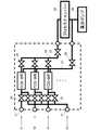
- FIG. 4 is a system diagram showing a configuration of a gas supply box using the pressure type flow rate control device according to the present invention.
- a pressure type flow control device 1 includes a main body 2, a pressure control control valve 6, an exhaust valve 7, a pneumatically driven on-off valve 8, a first pressure sensor P. 1 and a second pressure sensor P 2 , an orifice OL, and the like. Further, in the embodiment of FIG. 2, and one orifice OL and FCS-WR pressure type flow rate control apparatus using a first pressure sensor P 1 and the second pressure sensor P 2 off valve 8 of the pneumatic type Thus, regardless of whether the fluid flowing through the orifice OL is in a critical state or a non-critical state, the flow rate can be controlled by adjusting the pressure using the pressure control control valve 6.
- valve seat 3 is an inlet side block
- 4 is a main body block
- 5 is an outlet side block
- 8 is a pneumatically driven on-off valve
- 8a is a pneumatic valve driving unit
- 9 is a fluid.
- An inlet, 10a is a fluid passage
- 10b is an exhaust passage
- 11 is a fluid outlet
- 12 is an exhaust outlet
- 13 is a gasket
- 14 is a control panel control board
- 15 is a casing
- 16 is a connector for connection.
- the main body 2 is formed by assembling and integrating an inlet side block 3, a main body block 4 and an outlet side block 5 with fixing bolts (not shown), a pressure control control valve 6, an exhaust valve 7,
- the first pressure sensor P 1 and the second pressure sensor P 2 are screwed and fixed to the main body 2 respectively.
- the second pressure sensor P 2 is placed in the lower part of the inner surface of the outlet side block 5, it is communicated with the fluid passage 10a so as to avoid the intersection of the exhaust passage 10b.
- the pressure control control valve 6 is an on-off valve using a piezo drive element 6a having a known metal diaphragm as a valve body 20.
- the piezo drive element 6a is expanded by energizing the piezo drive element 6a, and the cylindrical body 17 is elastic.
- the valve body presser 19 is moved upward by pushing it upward against the elastic force of 18, and the valve body 20 is separated from the valve seat 2a by the self-elastic force of the diaphragm valve body 20 to open the valve.
- the valve opening is adjusted by changing the voltage applied to the piezo drive element 6a.
- the structure and operation of the exhaust valve 7 can be the same as those of the pressure control control valve 6, and the valve opening degree can be controlled by adjusting the extension amount of the piezo drive element 7a.
- the exhaust valve 7 may be a known pneumatically driven or electromagnetically driven opening / closing control valve instead of the piezo-driven metal diaphragm type opening / closing valve. It is also possible to use a valve. Further, it is possible to control all the operations of the pressure control control valve 6, the exhaust valve 7, the on-off valve 8, etc. automatically via the panel control board 14. It is the same as the case of.
- the orifice OL and the on-off valve 8 are integrally assembled in order to reduce the size of the device and reduce the fluid passage volume.
- a type on-off valve is used. Since the structure of the orifice built-in on-off valve 8 itself is known (Patent Document 6, Japanese Patent Laid-Open No. 2000-213667, etc.), detailed description thereof is omitted here, but as shown in FIG.
- a hole 34 for accommodating the valve mechanism is provided on the upper surface of the outlet side block 5, and an orifice OL, a valve seat ring 30, a valve body (metal diaphragm) 20, a presser cylinder 33, a valve body presser 19, a stem 31,
- the constituent members of the valve mechanism such as the spring 32 are arranged, and the on-off valve 8 is fixed on the outlet side block 5 constituting the main body 2.
- the orifice built-in type on-off valve By using the orifice built-in type on-off valve, the internal volume between the orifice and the valve element can be minimized, and the rising and falling characteristics of the flow rate when the valve is opened and closed are improved.
- the orifice built-in type on-off valve has an orifice on the upstream side and a valve body on the downstream side. In this case, the fall characteristics are affected only by the operation of the on-off valve, and the internal volume is minimal. Therefore, the influence of the internal volume on the rise characteristic is small.
- the valve body By reversing the mounting direction of the opening / closing valve with built-in orifice, the valve body is provided on the upstream side and the orifice is provided on the downstream side. In this case, the rise characteristic is affected only by the operation of the open / close valve, and the fall characteristic The effect of the internal volume is small.
- FIG. 4 is a system diagram showing the configuration of the gas supply box using the pressure type flow rate control device according to the present invention, and the three kinds of real gases G 1 to G 3 and G 2 are used individually or appropriately. These gas species are mixed at a predetermined ratio and supplied to the process chamber 29.
- the FCS-N internal space gas is forcibly exhausted (vacuum exhausted) by the vacuum pump 28 through the outlet side opening / closing valve 24 of the exhaust line 27 via the exhaust valve 7 (not shown). It is.
- 21 is a gas supply port
- 22 is a supply side switching valve
- 23 is an outlet side switching valve
- 26 is a mixed gas supply line.
- FCS-WR type pressure type flow control device using the orifice built-in on-off valve 8 shown in FIG.
- FCS-N type, FCS-SN type, and FCS-SWR type may be used as the flow rate control device, and any of the previous types of pressure flow control devices shown in FIG. Can also be applied to the practice of the present invention.
- the highly accurate pulse flow rate control can be performed with a pulse interval of several tens to several hundreds msec. Since the operating principle and configuration of the pressure type flow rate control device are already known, detailed description thereof is omitted here.
- the present invention can be applied not only to gas supply facilities and gas supply devices for semiconductor manufacturing apparatuses, but also to flow control devices for various gas supply facilities such as the chemical industry and the food industry.
Abstract
Description
介して比較回路CDbへ入力され、ここで前記温度補正・流量演算回路CDaからの流量演算値Qtと比較される。比較の結果、設定流量入力信号Qsと流量演算値Qtとの間に差異があると、コントロール弁CVの駆動部へ制御信号Pdが出力され、これによりコントロール弁CVが駆動され、設定流量入力信号Qsと演算流量値Qtとの差(Qs-Qt)が零となるように自動調整される。
尚、上記ガス流量QをQ=KP1(但しKは定数)として演算する方式の圧力式流量制御装置は、一般にFCS-N型と呼ばれており、また、ガス流量QをQ=KP2 m(P1-P2)n(但しK、m、nは定数)として演算する方式の圧力式流量制御装置は、FCS-WR型と呼ばれている。
尚、図6において、P1,P2は圧力センサ、CVはコントロール弁、OLはオリフィ
ス、OL1は小口径オリフィス、OL2は大口径オリフィス、ORVはオリフィス切換弁であ
る。
本発明は、流量制御開始時の上記オーバーシュートの問題を解決せんとするものであり、パルス流量制御可能な圧力式流量制御装置及びその流量制御開始時のオーバーシュート防止方法の提供を発明の主要な課題とするものである。
即ち、本発明に係る圧力式流量制御装置は、流体入口と流体出口との間を連通する流体通路及び該流体通路から分岐して該流体通路と排気出口との間を連通する排気通路を設けた本体と、該本体の前記流体入口側に固定されて前記流体通路の上流側を開閉する圧力制御用コントロール弁と、該圧力制御用コントロール弁の下流側の前記流体通路内圧を検出する第1圧力センサと、前記排気通路の分岐箇所より下流の前記流体通路内に設けたオリフィスと、前記第1圧力センサの下流側の前記流体通路を開閉する開閉弁と、前記排気通路を開閉する排気用弁と、を備えることを基本構成とする。当該圧力式流量制御装置による流体流量の制御開始前に圧力制御用コントロール弁と排気用弁を作動して圧力制御用コントロール弁と開閉弁の間の流体通路空間内を強制排気することにより、流量制御開始時のオーバーシュートを防止すること可能にする。
図1は本発明の圧力式流量制御装置の基本構成を示す系統図であり、図2は本発明に係る圧力式流量制御装置の基本構成を示す縦断面図、図3は本発明に係る圧力式流量制御装置の平面図(a)と正面図(b)及びオリフィス内蔵型開閉弁の部分拡大断面図(c)であ
る。
また、図4は、本発明に係る圧力式流量制御装置を用いたガス供給ボックスの構成を示す系統図である。
面の下部に配置されており、排気通路10bとの交差を避けて流体通路10aへ連通されている。
また、排気用弁7の構造及び作動は、圧力制御用コントロール弁6の場合と同一とすることができ、ピエゾ駆動素子7aの伸長量調節により、弁開度制御が行なうことができる。
尚、排気用弁7には、上記ピエゾ駆動式金属ダイヤフラム型開閉弁に代えて、公知の空気圧駆動式や電磁駆動式の開閉制御弁を用いることも可能であり、また、コントロール弁ではなく開閉弁を用いることも可能である。
更に、前記圧力制御用コントロール弁6、排気用弁7及び開閉弁8等の作動制御は、パネルコントロールボード14を介して全て自動的に行なわれ得ることは、従前のこの種圧力式流量制御装置の場合と同様である。
なお、オリフィス内蔵型開閉弁については、上流側にオリフィスが下流側に弁体が設けられているが、この場合、立下り特性は、開閉弁の動作のみの影響を受け、また内容積が極小であるため、立上り特性における内容積の影響が小さい。オリフィス内蔵型開閉弁の取付け方向を反対にすることで、上流側に弁体が、下流側にオリフィスが設けられるが、この場合は立上り特性は開閉弁の動作のみの影響を受け、立下り特性における内容積の影響が小さい。
尚、図4において、21はガス供給口、22は供給側切換弁、23は出口側切換弁、26は混合ガス供給ラインである。
尚、圧力式流量制御装置の作動原理や構成は既に公知であるため、ここではその詳細な説明を省略する。
2 本体
2a 弁座
3 入口側ブロック
4 本体ブロック
5 出口側ブロック
6 圧力制御用コントロール弁
6a ピエゾ駆動素子
7 排気用弁
7a ピエゾ駆動素子
8 空気圧駆動型の開閉弁
8a 空気圧型弁駆動部
9 流体入口
10a 流体通路
10b 排気通路
10c 漏洩検査用通路
11 流体出口
12 排気出口
13 ガスケット
14 パネルコントロールボード
15 ケーシング
16 接続用コネクタ
17 円筒体
18 弾性体
19 弁体押さえ
20 弁体
21 ガス供給口
22 供給側切換弁
23 出口側開閉弁
24 出口側開閉弁
26 混合ガス供給ライン
27 真空排気ライン
28 真空ポンプ
29 プロセスチャンバ
30 弁座用リング
31 ステム
32 スプリング
33 押え筒体
34 孔部
P1 第1圧力センサ
P2 第2圧力センサ
OL オリフィス
G1~G3 実ガス
Claims (13)
- 流体入口と流体出口との間を連通する流体通路と、該流体通路から分岐して該流体通路と排気出口との間を連通する排気通路とを設けた本体と、
前記本体の前記流体入口側に固定されて前記流体通路の上流側を開閉する圧力制御用コントロール弁と、
前記圧力制御用コントロール弁の下流側の流体通路内圧を検出する第1圧力センサと、
前記排気通路の分岐箇所より下流の前記流体通路内に設けたオリフィスと、
前記第1圧力センサの下流側の前記流体通路を開閉する開閉弁と、
前記排気通路を開閉する排気用弁と、を備えることを特徴とする圧力式流量制御装置。 - 流量制御時に前記開閉弁を開閉することにより流量のパルス制御がなされる請求項1に記載の圧力式流量制御装置。
- 前記開閉弁が前記オリフィスの下流側に設けられる請求項1に記載の圧力式流量制御装置。
- 前記排気用弁を制御弁とした請求項1に記載の圧力式流量制御装置
- 前記本体に、オリフィス下流側の前記流体通路内圧を検出する第2圧力センサを設けた請求項1に記載の圧力式流量制御装置。
- 前記第2圧力センサは、前記開閉弁の下流側の前記流体通路内圧を検出するセンサである請求項3に記載の圧力式流量制御装置。
- 前記オリフィス及び前記開閉弁は、オリフィスと開閉弁を一体的に組み付け固定した構成のオリフィス内蔵型弁である請求項1に記載の圧力式流量制御装置。
- 複数のオリフィスを並列状に連結し、切換弁により少なくとも一つのオリフィスに流体を流通させるように構成した請求項1に記載の圧力式流量制御装置。
- 複数のオリフィスを並列状に連結し、切換弁により少なくとも一つのオリフィスに流体を流通させると共に、オリフィス下流側の流体通路内圧を検出する圧力センサを備える請求項1に記載の圧力式流量制御装置。
- 前記圧力制御用コントロール弁が、ピエゾ素子駆動型の金属ダイヤフラム式制御弁である請求項1に記載の圧力式流量制御装置。
- 前記開閉弁は、空気圧駆動弁又は電磁駆動弁である請求項1に記載の圧力式流量制御装置。
- 前記排気出口に接続した真空ポンプにより前記排気通路内を強制排気する構成とした請求項1に記載の圧力式流量制御装置。
- 流体入口と流体出口との間を連通する流体通路及び該流体通路から分岐して該流体通路と排気出口との間を連通する排気通路とを設けた本体と、前記本体の流体入口側に固定されて前記流体通路の上流側を開閉する圧力制御用コントロール弁と、該圧力制御用コントロール弁の下流側の流体通路内圧を検出する第1圧力センサと、前記排気通路の分岐箇所より下流の流体通路内に設けたオリフィスと、前記第1圧力センサの下流側の前記流体通路を開閉する開閉弁と、前記排気通路を開閉する排気用弁と、を備える圧力式流量制御装置のオーバーシュート防止方法であって、前記圧力式流量制御装置による流量制御開始前に前記排気用弁を作動して前記圧力制御用コントロール弁と開閉弁間の流体通路空間内を強制排気することにより、流量制御開始時のオーバーシュートを防止する前記方法。
Priority Applications (3)
| Application Number | Priority Date | Filing Date | Title |
|---|---|---|---|
| US15/110,208 US9841770B2 (en) | 2014-01-21 | 2015-01-15 | Pressure-type flow control device and method for preventing overshooting at start of flow control performed by said device |
| CN201580002126.5A CN105940357B (zh) | 2014-01-21 | 2015-01-15 | 压力式流量控制装置及其流量控制开始时的超量防止方法 |
| KR1020167005843A KR101887364B1 (ko) | 2014-01-21 | 2015-01-15 | 압력식 유량 제어 장치 및 그 유량 제어 개시 시의 오버슈트 방지 방법 |
Applications Claiming Priority (2)
| Application Number | Priority Date | Filing Date | Title |
|---|---|---|---|
| JP2014008831A JP6321972B2 (ja) | 2014-01-21 | 2014-01-21 | 圧力式流量制御装置及びその流量制御開始時のオーバーシュート防止方法 |
| JP2014-008831 | 2014-01-21 |
Publications (1)
| Publication Number | Publication Date |
|---|---|
| WO2015111391A1 true WO2015111391A1 (ja) | 2015-07-30 |
Family
ID=53681205
Family Applications (1)
| Application Number | Title | Priority Date | Filing Date |
|---|---|---|---|
| PCT/JP2015/000154 WO2015111391A1 (ja) | 2014-01-21 | 2015-01-15 | 圧力式流量制御装置及びその流量制御開始時のオーバーシュート防止方法 |
Country Status (6)
| Country | Link |
|---|---|
| US (1) | US9841770B2 (ja) |
| JP (1) | JP6321972B2 (ja) |
| KR (1) | KR101887364B1 (ja) |
| CN (1) | CN105940357B (ja) |
| TW (1) | TWI537696B (ja) |
| WO (1) | WO2015111391A1 (ja) |
Cited By (3)
| Publication number | Priority date | Publication date | Assignee | Title |
|---|---|---|---|---|
| KR20180006856A (ko) * | 2016-07-11 | 2018-01-19 | 도쿄엘렉트론가부시키가이샤 | 가스 공급 시스템, 기판 처리 시스템 및 가스 공급 방법 |
| JP2018098208A (ja) * | 2016-12-15 | 2018-06-21 | サーモ フィッシャー サイエンティフィック (ブレーメン) ゲーエムベーハー | 改善されたガス流量制御 |
| WO2023182105A1 (ja) * | 2022-03-22 | 2023-09-28 | 株式会社フジキン | 流量制御装置の排気構造、排気方法及びそれを備えたガス供給システム及びガス供給方法 |
Families Citing this family (18)
| Publication number | Priority date | Publication date | Assignee | Title |
|---|---|---|---|---|
| JP6372998B2 (ja) * | 2013-12-05 | 2018-08-15 | 株式会社フジキン | 圧力式流量制御装置 |
| JP6539482B2 (ja) * | 2015-04-15 | 2019-07-03 | 株式会社フジキン | 遮断開放器 |
| CN109074104B (zh) * | 2016-04-28 | 2021-07-16 | 株式会社富士金 | 流体控制系统以及流体控制装置的控制方法 |
| US11144075B2 (en) | 2016-06-30 | 2021-10-12 | Ichor Systems, Inc. | Flow control system, method, and apparatus |
| US10679880B2 (en) | 2016-09-27 | 2020-06-09 | Ichor Systems, Inc. | Method of achieving improved transient response in apparatus for controlling flow and system for accomplishing same |
| US10665430B2 (en) * | 2016-07-11 | 2020-05-26 | Tokyo Electron Limited | Gas supply system, substrate processing system and gas supply method |
| JP6786096B2 (ja) * | 2016-07-28 | 2020-11-18 | 株式会社フジキン | 圧力式流量制御装置 |
| JP7245600B2 (ja) * | 2016-12-15 | 2023-03-24 | 株式会社堀場エステック | 流量制御装置、及び、流量制御装置用プログラム |
| JP7107648B2 (ja) * | 2017-07-11 | 2022-07-27 | 株式会社堀場エステック | 流体制御装置、流体制御システム、流体制御方法、及び、流体制御装置用プログラム |
| JP7157476B2 (ja) * | 2018-04-27 | 2022-10-20 | 株式会社フジキン | 流量制御方法および流量制御装置 |
| DE102018004341A1 (de) * | 2018-05-31 | 2019-12-05 | Drägerwerk AG & Co. KGaA | Beatmungsgerät und Verfahren zum Betrieb eines Beatmungsgeräts |
| KR102421587B1 (ko) | 2018-06-26 | 2022-07-15 | 가부시키가이샤 후지킨 | 유량 제어 방법 및 유량 제어 장치 |
| CN112888893A (zh) | 2018-10-26 | 2021-06-01 | 株式会社富士金 | 流体供给系统、流体控制装置以及半导体制造装置 |
| WO2021019922A1 (ja) * | 2019-07-31 | 2021-02-04 | 株式会社フジキン | バルブ装置、流体制御装置及びバルブ装置の製造方法 |
| JP7045738B1 (ja) * | 2021-03-23 | 2022-04-01 | 株式会社リンテック | 常時閉型流量制御バルブ |
| US20220372997A1 (en) * | 2021-05-24 | 2022-11-24 | Festo Se & Co. Kg | Fluid control system |
| KR20230000975A (ko) * | 2021-06-25 | 2023-01-03 | 가부시키가이샤 호리바 에스텍 | 유체 제어 장치, 유체 제어 시스템, 유체 제어 장치용 프로그램 및 유체 제어 방법 |
| WO2023053724A1 (ja) * | 2021-09-30 | 2023-04-06 | 株式会社フジキン | オリフィス内蔵バルブおよび流量制御装置 |
Citations (7)
| Publication number | Priority date | Publication date | Assignee | Title |
|---|---|---|---|---|
| JPS6328875A (ja) * | 1986-07-23 | 1988-02-06 | Anelva Corp | ガス導入方法 |
| JPH08338546A (ja) * | 1995-06-12 | 1996-12-24 | Fujikin:Kk | 圧力式流量制御装置 |
| JPH109996A (ja) * | 1996-06-21 | 1998-01-16 | Mitsubishi Heavy Ind Ltd | 流量制御装置 |
| JPH1055218A (ja) * | 1996-08-12 | 1998-02-24 | Tadahiro Omi | 圧力式流量制御装置 |
| JP2003195948A (ja) * | 2001-12-28 | 2003-07-11 | Tadahiro Omi | 改良型圧力式流量制御装置 |
| JP2006330851A (ja) * | 2005-05-23 | 2006-12-07 | Fujikin Inc | 改良型圧力式流量制御装置 |
| WO2009141947A1 (ja) * | 2008-05-21 | 2009-11-26 | 株式会社フジキン | 圧力式流量制御装置を用いた流体の非連続式流量切替制御方法 |
Family Cites Families (6)
| Publication number | Priority date | Publication date | Assignee | Title |
|---|---|---|---|---|
| US4550747A (en) * | 1983-10-05 | 1985-11-05 | Digital Hydraulics, Inc. | Digital fluid pressure flow rate and position control system |
| US5739429A (en) * | 1995-07-13 | 1998-04-14 | Nordson Corporation | Powder coating system incorporating improved method and apparatus for monitoring flow rate of entrained particulate flow |
| US5865205A (en) * | 1997-04-17 | 1999-02-02 | Applied Materials, Inc. | Dynamic gas flow controller |
| JP4137267B2 (ja) | 1999-01-28 | 2008-08-20 | 忠弘 大見 | オリフィス内蔵弁 |
| JP4648098B2 (ja) * | 2005-06-06 | 2011-03-09 | シーケーディ株式会社 | 流量制御機器絶対流量検定システム |
| CN101563023B (zh) | 2006-12-20 | 2012-09-05 | 皇家飞利浦电子股份有限公司 | 用于影响和/或检测作用区域中的磁性粒子的布置和方法 |
-
2014
- 2014-01-21 JP JP2014008831A patent/JP6321972B2/ja active Active
-
2015
- 2015-01-15 WO PCT/JP2015/000154 patent/WO2015111391A1/ja active Application Filing
- 2015-01-15 KR KR1020167005843A patent/KR101887364B1/ko active IP Right Grant
- 2015-01-15 US US15/110,208 patent/US9841770B2/en active Active
- 2015-01-15 CN CN201580002126.5A patent/CN105940357B/zh not_active Expired - Fee Related
- 2015-01-20 TW TW104101810A patent/TWI537696B/zh active
Patent Citations (7)
| Publication number | Priority date | Publication date | Assignee | Title |
|---|---|---|---|---|
| JPS6328875A (ja) * | 1986-07-23 | 1988-02-06 | Anelva Corp | ガス導入方法 |
| JPH08338546A (ja) * | 1995-06-12 | 1996-12-24 | Fujikin:Kk | 圧力式流量制御装置 |
| JPH109996A (ja) * | 1996-06-21 | 1998-01-16 | Mitsubishi Heavy Ind Ltd | 流量制御装置 |
| JPH1055218A (ja) * | 1996-08-12 | 1998-02-24 | Tadahiro Omi | 圧力式流量制御装置 |
| JP2003195948A (ja) * | 2001-12-28 | 2003-07-11 | Tadahiro Omi | 改良型圧力式流量制御装置 |
| JP2006330851A (ja) * | 2005-05-23 | 2006-12-07 | Fujikin Inc | 改良型圧力式流量制御装置 |
| WO2009141947A1 (ja) * | 2008-05-21 | 2009-11-26 | 株式会社フジキン | 圧力式流量制御装置を用いた流体の非連続式流量切替制御方法 |
Cited By (8)
| Publication number | Priority date | Publication date | Assignee | Title |
|---|---|---|---|---|
| KR20180006856A (ko) * | 2016-07-11 | 2018-01-19 | 도쿄엘렉트론가부시키가이샤 | 가스 공급 시스템, 기판 처리 시스템 및 가스 공급 방법 |
| JP2018014479A (ja) * | 2016-07-11 | 2018-01-25 | 東京エレクトロン株式会社 | ガス供給システム、基板処理システム及びガス供給方法 |
| KR102313423B1 (ko) | 2016-07-11 | 2021-10-18 | 도쿄엘렉트론가부시키가이샤 | 가스 공급 시스템, 기판 처리 시스템 및 가스 공급 방법 |
| KR20210125971A (ko) * | 2016-07-11 | 2021-10-19 | 도쿄엘렉트론가부시키가이샤 | 가스 공급 시스템, 기판 처리 시스템 및 가스 공급 방법 |
| KR102358828B1 (ko) | 2016-07-11 | 2022-02-08 | 도쿄엘렉트론가부시키가이샤 | 가스 공급 시스템, 기판 처리 시스템 및 가스 공급 방법 |
| JP2018098208A (ja) * | 2016-12-15 | 2018-06-21 | サーモ フィッシャー サイエンティフィック (ブレーメン) ゲーエムベーハー | 改善されたガス流量制御 |
| US10388498B2 (en) | 2016-12-15 | 2019-08-20 | Thermo Fisher Scientific (Bremen) Gmbh | Gas flow control |
| WO2023182105A1 (ja) * | 2022-03-22 | 2023-09-28 | 株式会社フジキン | 流量制御装置の排気構造、排気方法及びそれを備えたガス供給システム及びガス供給方法 |
Also Published As
| Publication number | Publication date |
|---|---|
| KR20160040285A (ko) | 2016-04-12 |
| US20160327963A1 (en) | 2016-11-10 |
| CN105940357B (zh) | 2019-05-14 |
| TWI537696B (zh) | 2016-06-11 |
| CN105940357A (zh) | 2016-09-14 |
| TW201541214A (zh) | 2015-11-01 |
| JP6321972B2 (ja) | 2018-05-09 |
| US9841770B2 (en) | 2017-12-12 |
| KR101887364B1 (ko) | 2018-08-10 |
| JP2015138338A (ja) | 2015-07-30 |
Similar Documents
| Publication | Publication Date | Title |
|---|---|---|
| WO2015111391A1 (ja) | 圧力式流量制御装置及びその流量制御開始時のオーバーシュート防止方法 | |
| JP2015138338A5 (ja) | ||
| JP6216389B2 (ja) | 圧力式流量制御装置 | |
| CN108027618B (zh) | 压力式流量控制装置及其异常检测方法 | |
| JP6193679B2 (ja) | ガス分流供給装置及びガス分流供給方法 | |
| US8033801B2 (en) | Liquid chemical supply system and liquid chemical supply control device | |
| TWI770130B (zh) | 真空閥的優化壓力調節 | |
| KR101677971B1 (ko) | 반도체 제조 장치의 가스 분류 공급 장치 | |
| JP2005196788A (ja) | 流体の流量を制御する装置、方法及びシステム | |
| US20090292399A1 (en) | Method for detecting malfunction of valve on the downstream side of throttle mechanism of pressure type flow control apparatus | |
| WO2018021327A1 (ja) | 圧力式流量制御装置 | |
| JP2008234027A (ja) | ガス供給ユニット | |
| JP7197897B2 (ja) | コントロール弁のシートリーク検知方法 | |
| JP4986125B2 (ja) | 質量流量制御装置及びガス供給ユニット | |
| JP7232506B2 (ja) | 流量圧力制御装置 | |
| KR20150113507A (ko) | 유체의 제어 방법 | |
| JP2001306153A (ja) | 質量流量制御装置 |
Legal Events
| Date | Code | Title | Description |
|---|---|---|---|
| 121 | Ep: the epo has been informed by wipo that ep was designated in this application |
Ref document number: 15740590 Country of ref document: EP Kind code of ref document: A1 |
|
| ENP | Entry into the national phase |
Ref document number: 20167005843 Country of ref document: KR Kind code of ref document: A |
|
| WWE | Wipo information: entry into national phase |
Ref document number: 15110208 Country of ref document: US |
|
| NENP | Non-entry into the national phase |
Ref country code: DE |
|
| 122 | Ep: pct application non-entry in european phase |
Ref document number: 15740590 Country of ref document: EP Kind code of ref document: A1 |