WO2021019922A1 - バルブ装置、流体制御装置及びバルブ装置の製造方法 - Google Patents
バルブ装置、流体制御装置及びバルブ装置の製造方法 Download PDFInfo
- Publication number
- WO2021019922A1 WO2021019922A1 PCT/JP2020/022873 JP2020022873W WO2021019922A1 WO 2021019922 A1 WO2021019922 A1 WO 2021019922A1 JP 2020022873 W JP2020022873 W JP 2020022873W WO 2021019922 A1 WO2021019922 A1 WO 2021019922A1
- Authority
- WO
- WIPO (PCT)
- Prior art keywords
- flow path
- diaphragm
- valve device
- bonnet
- female screw
- Prior art date
Links
Images


Classifications
-
- F—MECHANICAL ENGINEERING; LIGHTING; HEATING; WEAPONS; BLASTING
- F16—ENGINEERING ELEMENTS AND UNITS; GENERAL MEASURES FOR PRODUCING AND MAINTAINING EFFECTIVE FUNCTIONING OF MACHINES OR INSTALLATIONS; THERMAL INSULATION IN GENERAL
- F16K—VALVES; TAPS; COCKS; ACTUATING-FLOATS; DEVICES FOR VENTING OR AERATING
- F16K7/00—Diaphragm valves or cut-off apparatus, e.g. with a member deformed, but not moved bodily, to close the passage ; Pinch valves
- F16K7/12—Diaphragm valves or cut-off apparatus, e.g. with a member deformed, but not moved bodily, to close the passage ; Pinch valves with flat, dished, or bowl-shaped diaphragm
- F16K7/14—Diaphragm valves or cut-off apparatus, e.g. with a member deformed, but not moved bodily, to close the passage ; Pinch valves with flat, dished, or bowl-shaped diaphragm arranged to be deformed against a flat seat
- F16K7/16—Diaphragm valves or cut-off apparatus, e.g. with a member deformed, but not moved bodily, to close the passage ; Pinch valves with flat, dished, or bowl-shaped diaphragm arranged to be deformed against a flat seat the diaphragm being mechanically actuated, e.g. by screw-spindle or cam
-
- F—MECHANICAL ENGINEERING; LIGHTING; HEATING; WEAPONS; BLASTING
- F16—ENGINEERING ELEMENTS AND UNITS; GENERAL MEASURES FOR PRODUCING AND MAINTAINING EFFECTIVE FUNCTIONING OF MACHINES OR INSTALLATIONS; THERMAL INSULATION IN GENERAL
- F16K—VALVES; TAPS; COCKS; ACTUATING-FLOATS; DEVICES FOR VENTING OR AERATING
- F16K7/00—Diaphragm valves or cut-off apparatus, e.g. with a member deformed, but not moved bodily, to close the passage ; Pinch valves
- F16K7/12—Diaphragm valves or cut-off apparatus, e.g. with a member deformed, but not moved bodily, to close the passage ; Pinch valves with flat, dished, or bowl-shaped diaphragm
- F16K7/14—Diaphragm valves or cut-off apparatus, e.g. with a member deformed, but not moved bodily, to close the passage ; Pinch valves with flat, dished, or bowl-shaped diaphragm arranged to be deformed against a flat seat
- F16K7/17—Diaphragm valves or cut-off apparatus, e.g. with a member deformed, but not moved bodily, to close the passage ; Pinch valves with flat, dished, or bowl-shaped diaphragm arranged to be deformed against a flat seat the diaphragm being actuated by fluid pressure
-
- F—MECHANICAL ENGINEERING; LIGHTING; HEATING; WEAPONS; BLASTING
- F16—ENGINEERING ELEMENTS AND UNITS; GENERAL MEASURES FOR PRODUCING AND MAINTAINING EFFECTIVE FUNCTIONING OF MACHINES OR INSTALLATIONS; THERMAL INSULATION IN GENERAL
- F16K—VALVES; TAPS; COCKS; ACTUATING-FLOATS; DEVICES FOR VENTING OR AERATING
- F16K31/00—Actuating devices; Operating means; Releasing devices
- F16K31/12—Actuating devices; Operating means; Releasing devices actuated by fluid
- F16K31/122—Actuating devices; Operating means; Releasing devices actuated by fluid the fluid acting on a piston
- F16K31/1221—Actuating devices; Operating means; Releasing devices actuated by fluid the fluid acting on a piston one side of the piston being spring-loaded
-
- F—MECHANICAL ENGINEERING; LIGHTING; HEATING; WEAPONS; BLASTING
- F16—ENGINEERING ELEMENTS AND UNITS; GENERAL MEASURES FOR PRODUCING AND MAINTAINING EFFECTIVE FUNCTIONING OF MACHINES OR INSTALLATIONS; THERMAL INSULATION IN GENERAL
- F16K—VALVES; TAPS; COCKS; ACTUATING-FLOATS; DEVICES FOR VENTING OR AERATING
- F16K31/00—Actuating devices; Operating means; Releasing devices
- F16K31/12—Actuating devices; Operating means; Releasing devices actuated by fluid
- F16K31/122—Actuating devices; Operating means; Releasing devices actuated by fluid the fluid acting on a piston
- F16K31/1225—Actuating devices; Operating means; Releasing devices actuated by fluid the fluid acting on a piston with a plurality of pistons
-
- F—MECHANICAL ENGINEERING; LIGHTING; HEATING; WEAPONS; BLASTING
- F16—ENGINEERING ELEMENTS AND UNITS; GENERAL MEASURES FOR PRODUCING AND MAINTAINING EFFECTIVE FUNCTIONING OF MACHINES OR INSTALLATIONS; THERMAL INSULATION IN GENERAL
- F16K—VALVES; TAPS; COCKS; ACTUATING-FLOATS; DEVICES FOR VENTING OR AERATING
- F16K31/00—Actuating devices; Operating means; Releasing devices
- F16K31/44—Mechanical actuating means
- F16K31/50—Mechanical actuating means with screw-spindle or internally threaded actuating means
-
- F—MECHANICAL ENGINEERING; LIGHTING; HEATING; WEAPONS; BLASTING
- F16—ENGINEERING ELEMENTS AND UNITS; GENERAL MEASURES FOR PRODUCING AND MAINTAINING EFFECTIVE FUNCTIONING OF MACHINES OR INSTALLATIONS; THERMAL INSULATION IN GENERAL
- F16L—PIPES; JOINTS OR FITTINGS FOR PIPES; SUPPORTS FOR PIPES, CABLES OR PROTECTIVE TUBING; MEANS FOR THERMAL INSULATION IN GENERAL
- F16L41/00—Branching pipes; Joining pipes to walls
- F16L41/02—Branch units, e.g. made in one piece, welded, riveted
Definitions
- the present invention relates to a valve device, a fluid control device, and a method for manufacturing a valve device.
- JP2016-161022A includes a flow path block in which a flow path is formed, a diaphragm that opens and closes the flow path, an actuator that pushes the diaphragm via a diaphragm retainer, and a bonnet that connects the flow path block and the actuator.
- the valve device provided is disclosed.
- the valve device of JP2016-161022A has a problem that the flow rate of the fluid flowing through the flow path varies when the diaphragm is fully opened due to the variation in the dimensions of each member constituting the valve device. Therefore, it is required to adjust the Cv value related to this flow rate when assembling the valve device.
- the Cv value is a flow rate value expressed in US gallons / min when water is flowed at 60 degrees Fahrenheit with a pressure difference of 1 Psi in a specific operating range.
- the present invention has been made in view of the above circumstances, and an object of the present invention is to provide a valve device, a fluid control device, and a method for manufacturing a valve device capable of adjusting a Cv value at the time of assembly.
- the flow path block in which the flow path is formed the diaphragm that opens and closes the flow path, the diaphragm retainer that presses the diaphragm, and the diaphragm that presses the diaphragm via the diaphragm retainer.
- a female screw is formed on the inner peripheral surface of the actuator, and the tubular bonnet connecting the flow path block and the actuator is screwed into the female screw and abuts on the diaphragm retainer to open the diaphragm.
- a valve device comprising a tubular position adjusting member for adjusting the valve position and an annular lock nut for locking the position adjusting member by being screwed into the female screw.
- a method for manufacturing a valve device for manufacturing a valve device which comprises a diaphragm installation step of installing a diaphragm for opening and closing the flow path in a flow path block in which the flow path is formed.
- a method for manufacturing a valve device includes a locking step of locking the valve device and an actuator mounting step of attaching an actuator for pressing the diaphragm to the bonnet via the diaphragm retainer.
- the Cv value can be adjusted at the time of assembly.
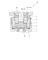
- FIG. 1 is a cross-sectional view showing a valve device according to an embodiment of the present invention.
- FIG. 2 is a top view showing the adjusting screw and the first rotating jig for rotating the adjusting screw.
- FIG. 3 is a top view showing the lock nut.
- FIG. 4 is a schematic view showing a second rotating jig for rotating the lock nut, (a) a schematic top view of the second rotating jig, and (b) a schematic cross-sectional view of the second rotating jig. ..
- FIG. 5 is a flowchart showing a manufacturing method of a valve device for manufacturing a valve device.
- FIG. 1 is a cross-sectional view showing a valve device according to an embodiment of the present invention.
- FIG. 2 is a top view showing the adjusting screw and the first rotating jig for rotating the adjusting screw.
- FIG. 3 is a top view showing the lock nut.
- FIG. 4 is a schematic view showing a second rotating
- FIG. 6 is a schematic view showing a state in which the adjusting screw is locked by screwing the lock nut with the second rotating jig in a state where the rotation of the adjusting screw is regulated by the first rotating jig.
- FIG. 7 is a perspective view showing an example of a fluid control device to which the valve device is applied.
- FIG. 8 is a cross-sectional view showing a main part of the valve device according to the first modification.
- FIG. 9 is a schematic cross-sectional view showing a main part of the valve device according to the second modification.
- valve device 1 First, the valve device 1 according to the present embodiment will be described with reference to FIGS. 1 to 4.
- FIG. 1 is a cross-sectional view showing the valve device 1.
- FIG. 2 is a top view showing the adjusting screw 8 and the first rotating jig 10 for rotating the adjusting screw 8.
- FIG. 3 is a top view showing the lock nut 9.
- FIG. 4 is a schematic view showing a second rotating jig 11 for rotating the lock nut 9, (a) a schematic top view of the second rotating jig 11, and (b) a schematic view of the second rotating jig 11. It is a sectional view.
- the valve device 1 is provided in a fluid control device (not shown) used for manufacturing a semiconductor.
- the fluid control device is used in a thin film forming step of forming a predetermined thin film on a substrate such as a semiconductor wafer by an ALD (Atomic Layer Deposition / that is, atomic layer deposition) method.
- ALD atomic layer deposition
- the valve device 1 includes a flow path block 2, a diaphragm 3, a diaphragm retainer 4, an actuator 5 as a drive unit, a bonnet 6, a spacer 7, an adjusting screw 8 as a position adjusting member, and a lock nut 9. Be prepared.
- the valve device 1 is an air operated valve that opens the diaphragm 3 by introducing drive air as a drive fluid into the actuator 5.
- the flow path block 2 has a fluid inflow flow path 21, a fluid outflow flow path 22, and a recess 23 in which the bonnet 6 is housed as a flow path.
- An annular valve seat 24 is provided on the peripheral edge of one end of the fluid inflow flow path 21.
- the flow path block 2 includes a peripheral wall 231 forming the recess 23.
- a female screw 232 screwed into the bonnet 6 is formed in the recess 23.
- the diaphragm 3 is a valve body for opening and closing the fluid inflow flow path 21 separated from the valve seat 24 or pressed by the valve seat 24.
- the diaphragm 3 is a diaphragm member that separates the flow path side and the actuator 5 side. Further, the diaphragm 3 is formed in an arc shape that rises toward the actuator 5 side (upper side in FIG. 1) in a natural state, and is made of, for example, a nickel alloy thin plate or the like. Normally, the diaphragm 3 is pressed by the diaphragm retainer 4 to the valve seat 24.
- the diaphragm retainer 4 is a retainer member for pressing the diaphragm 3 against the valve seat 24.
- the diaphragm retainer 4 is housed in the bonnet 6. Further, the diaphragm retainer 4 has a disk-shaped pressing body 41 as a guided portion, and a disk-shaped upper body that protrudes from the pressing body 41 toward the actuator 5 (upper side in FIG. 1) and has a smaller diameter than the pressing body 41.
- a disc shape as an insertion portion that protrudes from the protrusion 42 and the holding body 41 to the flow path block 2 side (lower side in FIG. 1) and has a smaller diameter than the holding body 41 and a larger diameter than the upper protrusion 42. It has a lower protrusion 43 and.
- the pressing body 41, the upper protrusion 42, and the lower protrusion 43 are formed coaxially.
- the presser body 41 is formed with an upper surface 411 as a contact surface and a lower surface 412 as a movement control surface opposite to the upper surface 411.
- the upper surface 411 is formed so as to be located outside the upper protrusion 42 and to face the end surface (lower end surface in FIG. 1) of the adjusting screw 8 on the flow path block 2 side.
- the lower surface 412 is formed so as to be located outside the lower protrusion 43 and to face the end surface (upper end surface in FIG. 1) of the spacer 7 on the actuator 5 side.
- the lower protrusion 43 is provided on the pressing body 41 by fitting, but the present invention is not limited to this, and for example, the lower protrusion 43 may be integrally molded with the pressing body 41.
- the actuator 5 blocks or communicates the fluid inflow flow path 21 and the fluid outflow flow path 22 by pressing or separating the diaphragm 3 from the valve seat 24 via the diaphragm retainer 4 housed in the bonnet 6.
- the actuator 5 includes a case 51 provided above the bonnet 6, a piston 52 slidably housed in the case 51, a coil spring 53 as an urging member for pressing the piston 52 toward the flow path block 2, and a piston. It has a stem 54 that moves in the axial direction (vertical direction in FIG. 1) in conjunction with the 52.
- the case 51 is a frame member for accommodating the piston 52 and the coil spring 53.
- the case 51 has a bottomed cylindrical first case 511 as an upper case and a second case 512 as a lower case connected to the first case 511 by screwing.
- the piston 52 is slidably accommodated in the accommodating space 513 formed by connecting the first case 511 and the second case 512.
- a coil spring 53 is housed above the piston 52.
- the first case 511 has a cylindrical peripheral wall 511a and a cylindrical top wall 511b provided at one end (upper end of FIG. 1) of the peripheral wall 511a.
- a female screw 511c screwed into the second case 512 is formed on the inner peripheral surface of the other end (lower end of FIG. 1) of the peripheral wall 511a.
- a stem guide hole 511d that penetrates the stem 54 in the axial direction (vertical direction in FIG. 1) is formed.
- the drive air is introduced into the actuator 5 from the drive air supply control unit (not shown) via the stem guide hole 511d.
- An annular groove 511e is formed on the top wall 511b as a spring accommodating chamber for accommodating the coil spring 53 so as to surround the stem guide hole 511d.
- the coil spring 53 is compressed so that one end (upper end of FIG. 1) abuts on the bottom of the annular groove 511e and the other end (lower end of FIG. 1) abuts on the first piston 521 described later of the piston 52. It is housed in the annular groove 511e.
- the peripheral wall 511a is formed with a through hole 511f and a through hole 511g for bleeding air that penetrate in the radial direction so as not to interfere with the female screw 511c.
- the through hole 511g is located below the through hole 511f.
- the top wall 511b is formed with a pair of engaging holes 511h to which a third rotating jig that rotates the actuator 5 is engaged so as not to interfere with the stem guide hole 511d.
- the second case 512 includes a cylindrical peripheral wall 512a, a disk-shaped bottom wall 512b provided at one end (lower end of FIG. 1) of the peripheral wall 512a, and a flow path block 2 side (lower side of FIG. 1) from the bottom wall 512b. ), It has a cylindrical stretched portion 514.
- a male screw 512c screwed into the female screw 511c is formed on the outer peripheral surface of the peripheral wall 512a.
- the peripheral wall 512a is formed with a through hole 512d for bleeding air that penetrates in the radial direction so as not to interfere with the male screw 512c.
- the through hole 511g of the first case 511 and the through hole 512d of the second case 512 communicate with each other.
- Through holes 512e through which the stem 54 is inserted are formed in the bottom wall 512b and the extension portion 514.
- a male screw 515 screwed into the bonnet 6 is provided on the outer peripheral surface of the stretched portion 514.
- the bottom wall 512b is formed with an annular flat contact surface 512f located on the outer peripheral side of the extending portion 514 and facing the bonnet 6.
- the piston 52 has a first piston 521 as an upper piston and a second piston 522 as a lower piston located below the first piston 521 in FIG. 1.
- a counter plate 55 located between the first piston 521 and the second piston 522 is fixed to the inner peripheral surface of the first case 511.
- a through hole through which the stem 54 is inserted is formed in the center of the counter plate 55.
- a first air introduction chamber 56 is formed between the second piston 522 and the second case 512.
- a second air introduction chamber 57 is formed between the first piston 521 and the counter plate 55.
- the stem 54 is formed with an axial flow path 54a, a first radial flow path 54b, and a second radial flow path 54c for introducing drive air into the first air introduction chamber 56 and the second air introduction chamber 57.
- the stem 54 is formed separately from the first shaft portion extending upward from the central portion of the first piston 521 and the first shaft portion, and is formed in the vertical direction from the central portion of the second piston 522. It has a second shaft portion that extends to, but is not limited to this, and for example, even if it has a shaft portion in which the first shaft portion and the second shaft portion are integrally formed. Good.
- the axial flow path 54a communicates with the stem guide hole 511d.
- the first radial flow path 54b is formed at the tip of the axial flow path 54a (lower end in FIG. 1) and communicates the axial flow path 54a with the first air introduction chamber 56.
- the second radial flow path 54c is formed near the center of the axial flow path 54a, and communicates the axial flow path 54a with the second air introduction chamber 57.
- a first communication chamber 58 is formed between the first piston 521 and the first case 511.
- the first communication chamber 58 communicates with the outside through the through hole 511f.
- a second communication chamber 59 is formed between the second piston 522 and the counter plate 55. The second communication chamber 59 communicates with the outside through the through hole 511g and the through hole 512d.
- An O-ring 12 is interposed between the stem guide hole 511d and one end of the stem 54.
- An O-ring 13 is interposed between the first piston 521 and the first case 511.
- An O-ring 14 is interposed between the counter plate 55 and the first case 511.
- An O-ring 15 is interposed between the counter plate 55 and the stem 54.
- An O-ring 16 is interposed between the second piston 522 and the second case 512.
- An O-ring 17 is interposed between the stem 54 and the through hole 512e.
- the bonnet 6 is a cylindrical connecting member that connects the flow path block 2 and the actuator 5.
- the diaphragm retainer 4, the adjusting screw 8, and the lock nut 9 are housed in the bonnet 6.
- a male screw 61 screwed into the female screw 232 of the recess 23 of the flow path block 2 is formed on the outer peripheral surface of the bonnet 6.
- the bonnet 6 is attached to the flow path block 2 by screwing the female screw 232 and the male screw 61.
- a hexagonal protrusion 62 that can be engaged with a monkey or the like is provided on the outer peripheral surface of the bonnet 6. The hexagonal protrusion 62 is located on the actuator 5 side (that is, above the male screw 61) with respect to the male screw 61.
- a female screw 63 is formed on the inner peripheral surface of the bonnet 6 located on the actuator 5 (upper side of FIG. 1) side.
- the adjusting screw 8, the lock nut 9, and the extension portion 514 of the actuator 5 are screwed into the female screw 63 in this order.
- An annular flat positioning surface 64 facing the contact surface 512f of the actuator 5 is formed at the upper end of the bonnet 6. Then, by screwing the male screw 515 of the stretched portion 514 and the female screw 63 of the bonnet 6, the stretched portion 514 of the actuator 5 can be screwed into the inner peripheral surface of the bonnet 6 until the contact surface 512f and the positioning surface 64 come into contact with each other. it can. As a result, the actuator 5 is positioned by the contact between the contact surface 512f and the positioning surface 64.
- An annular annular portion 65 having an inner diameter smaller than the inner diameter of the female screw 63 is formed at the lower end of the bonnet 6 as an end located on the flow path block 2 (lower side of FIG. 1). Then, the holding body 41 of the diaphragm holding 4 is guided in the vertical direction by the inner peripheral surface of the annular portion 65.
- the bonnet 6 is formed so that the female screw 63 and the annular portion 65 do not overlap in the vertical direction.
- An annular spacer 7 having an inner diameter smaller than the inner diameter of the annular portion 65 is provided between the lower end of the bonnet 6 and the bottom surface of the recess 23 of the flow path block 2.
- the outer peripheral edge of the diaphragm 3 is held between the spacer 7 and the bottom surface of the recess 23, and is fixed by screwing the bonnet 6 into the female screw 232 of the recess 23.
- the lower protrusion 43 of the diaphragm retainer 4 in contact with the diaphragm 3 is inserted into the inner peripheral side of the spacer 7.
- the adjusting screw 8 is a cylindrical position adjusting member for adjusting the valve opening position of the diaphragm 3 via the diaphragm retainer 4 according to the screwing amount of the bonnet 6 with respect to the female screw 63.
- the valve opening position of the diaphragm 3 refers to the position of the apex of the diaphragm 3.
- the adjusting screw 8 is provided between the lock nut 9 and the diaphragm retainer 4 along the vertical direction.
- the stem 54 of the actuator 5 and the upper protrusion 42 of the diaphragm retainer 4 are inserted so as to abut on the inner peripheral side of the adjusting screw 8, but the present invention is not limited to this. For example, either one of the stem 54 and the upper protrusion 42 may be inserted.
- the adjusting screw 8 is located on the flow path block 2 (lower side of FIG. 1) side of the large diameter portion 81 having a cylindrical shape as a screw portion to be screwed into the female screw 63, and the large diameter portion 81. It has a cylindrical small diameter portion 82 having an outer diameter smaller than the outer diameter of the above.
- the large diameter portion 81 and the small diameter portion 82 are formed coaxially.
- a male screw 811 screwed into the female screw 63 of the bonnet 6 is formed on the outer peripheral surface of the large diameter portion 81.
- the end surface (upper end surface in FIG. 1) of the large diameter portion 81 on the actuator 5 side comes into contact with the lock nut 9.
- the small diameter portion 82 is provided so that its tip (lower end in FIG. 1) is inserted into the annular portion 65 of the bonnet 6.
- the end surface (lower end surface in FIG. 1) of the small diameter portion 82 on the flow path block 2 side abuts on the upper surface 411 as the contact surface of the pressing body 41 of the diaphragm retainer 4.
- a first engaging portion 83 with which the first rotating jig 10 for rotating the adjusting screw 8 is engaged is formed on the inner peripheral surface of the adjusting screw 8.
- the first engaging portion 83 is composed of six semicircular concave grooves 831 formed on the inner peripheral surface of the adjusting screw 8 at predetermined intervals in a top view.
- the first rotating jig 10 is made of a hexagon wrench. The corners of the first rotating jig 10 can be accommodated in each of the six concave grooves 831.
- the concave groove 831 is provided so as to penetrate the large diameter portion 81 along the vertical direction and extend to the small diameter portion 82, but the present invention is not limited to this, and for example, the vertical direction. It may be provided so as to penetrate only the large diameter portion 81 along the vertical direction, or may be provided only in a part of the large diameter portion 81 along the vertical direction.
- the adjusting screw 8 is rotated in one direction (for example, clockwise) by the first rotating jig 10 and moves to the flow path block 2 (lower side in FIG. 1) while being screwed into the female screw 63 of the bonnet 6. To do.
- the diaphragm retainer 4 moves to the flow path block 2 (lower side in FIG. 1) side together with the adjusting screw 8.
- the diaphragm 3 is pressed toward the flow path block 2 (lower side in FIG. 1) by the movement of the diaphragm retainer 4, so that a gap (that is, Cv value) formed between the apex of the diaphragm 3 and the valve seat 24 is formed. ) Becomes smaller.
- the adjusting screw 8 is rotated in another direction (for example, counterclockwise direction) by the first rotating jig 10, and is loosened with respect to the female screw 63 of the bonnet 6 on the actuator 5 (upper side of FIG. 1) side.
- the diaphragm retainer 4 moves toward the actuator 5 (upper in FIG. 1) due to the restoring force of the diaphragm 3, thereby forming a gap (that is, a Cv value) between the apex of the diaphragm 3 and the valve seat 24. )
- a gap that is, a Cv value
- the adjusting screw 8 adjusts the Cv value at the time of assembling the valve device 1 by adjusting the valve opening position of the diaphragm 3 via the diaphragm retainer 4 according to the screwing amount of the bonnet 6 with respect to the female screw 63. can do. Therefore, it is possible to suppress the flow rate variation of the fluid flowing through the fluid inflow flow path 21 and the fluid outflow flow path 22 when fully opened.
- the movement of the diaphragm retainer 4 toward the flow path block 2 is restricted by the contact between the lower surface 412 as the movement restricting surface of the presser body 41 and the upper surface of the spacer 7.
- the gap that is, Cv value
- the adjusting screw 8 is excessively screwed into the female screw 63, and the diaphragm retainer 4 is released when the valve is closed. It is possible to suppress both the excessive pressing of the diaphragm 3 against the valve seat 24.
- the lock nut 9 is an annular lock member for locking the adjusting screw 8 after the valve opening position of the diaphragm 3 is adjusted. Further, the lock nut 9 is provided between the extension portion 514 of the actuator 5 and the adjusting screw 8 along the vertical direction.
- the stem 54 of the actuator 5 is inserted through the inner peripheral side of the lock nut 9, but the present invention is not limited to this, and for example, the upper protrusion 42 of the diaphragm retainer 4 is inserted. Alternatively, the stem 54 and the upper protrusion 42 may be inserted so as to be in contact with each other.
- a male screw 91 screwed into the female screw 63 of the bonnet 6 is formed on the outer peripheral surface of the lock nut 9.
- the end surface of the lock nut 9 on the flow path block 2 side comes into contact with the end surface of the large diameter portion 81 of the adjusting screw 8.
- a second rotating jig 11 for rotating the lock nut 9 is engaged with the end surface (upper end surface of FIG. 1) of the lock nut 9 on the actuator 5 side.
- the engaging portion 92 is formed.
- the second engaging portion 92 includes a pair of engaging holes 921.
- the second rotating jig 11 includes a cylindrical jig main body 111, a hexagonal protruding portion 112 provided on the outer peripheral surface of one end of the jig main body 111 and capable of engaging with a hexagon wrench. It has a pair of protrusions 113 that protrude from the other end of the jig body 111 and can be engaged with the pair of engagement holes 921. Since the jig body 111 of the second rotation jig 11 is formed with a through hole through which the first rotation jig 10 can be inserted, the first rotation jig 10 is inserted into the jig body 111 of the second rotation jig 11. It can be used by inserting it on the inner circumference side of.
- the lock nut 9 is screwed into the female screw 63 of the bonnet 6 by being rotated in one direction (for example, in the clockwise direction) by the second rotating jig 11.
- the lock nut 9 can lock the adjusting screw 8, so that the fluctuation of the Cv value due to the loosening of the adjusting screw 8 can be suppressed. Therefore, it is possible to further suppress the flow rate variation of the fluid flowing through the fluid inflow flow path 21 and the fluid outflow flow path 22 when fully opened.
- a first engaging portion 83 with which the first rotating jig 10 engages is formed in the region of the adjusting screw 8 which does not overlap with the lock nut 9 in the top view, and the lock nut 9 overlaps with the adjusting screw 8 in the top view.
- a second engaging portion 92 with which the second rotating jig 11 engages is formed in the region of.
- the first engaging portion 83 of the adjusting screw 8 is located on the inner diameter side of the second engaging portion 92 of the lock nut 9.
- the first rotating jig 10 inserts the inner peripheral side of the lock nut 9 between the pair of engaging holes 921, and the first engaging portion located on the inner diameter side of the second engaging portion 92. It can be engaged with 83 (see FIG. 6).
- the first rotating jig 10 and the second rotating jig 11 can be used by being engaged with the first engaging portion 83 and the second engaging portion 92 at the same time without interfering with each other.
- the first engaging portion 83 and the second engaging portion 92 are located in the region of the adjusting screw 8 that does not overlap the lock nut 9 in the top view and the region of the lock nut 9 that overlaps the adjusting screw 8 in the top view, respectively. It is formed.
- the first engaging portion 83 and the second engaging portion 92 are not limited to this, and for example, the region of the adjusting screw 8 overlapping the lock nut 9 in the top view and the adjusting screw 8 in the top view, respectively. It may be formed in the area of the overlapping lock nuts 9.
- valve device 1 for manufacturing the valve device 1 will be described with reference to FIGS. 5 and 6.
- FIG. 5 is a flowchart showing a manufacturing method of the valve device 1 for manufacturing the valve device 1.
- FIG. 6 is a schematic view showing a state in which the adjusting screw 8 is locked by screwing the lock nut 9 by the second rotating jig 11 in a state where the rotation of the adjusting screw 8 is regulated by the first rotating jig 10. ..
- step S1 the diaphragm 3 is installed in the flow path block 2. Specifically, in step S1, the diaphragm 3 is installed on the bottom surface of the recess 23 of the flow path block 2 so as to cover both the fluid inflow flow path 21 and the fluid outflow flow path 22.
- step S2 the bonnet 6 is attached to the flow path block 2.
- step S2 includes a spacer mounting step of mounting the spacer 7 on the diaphragm 3 so as to cover the outer peripheral edge of the diaphragm 3, and a spacer by screwing the bonnet 6 into the recess 23 of the flow path block 2.
- the bonnet screwing step of fixing the outer peripheral edge of the 7 and the diaphragm 3 is included.
- step S3 the diaphragm retainer 4 is installed on the bonnet 6 so as to come into contact with the diaphragm 3.
- step S4 the adjusting screw 8 is screwed into the female screw 63 of the bonnet 6 by the first rotating jig 10, and the valve opening position of the diaphragm 3 is adjusted via the diaphragm retainer 4.
- the Cv value can be adjusted when the valve device 1 is assembled.
- step S5 the adjusting screw 8 is locked by screwing the lock nut 9 into the female screw 63 of the bonnet 6 by the second rotating jig 11.
- step S5 as shown in FIG. 6, the lock nut 9 is screwed in by the second rotating jig 11 in a state where the rotation of the adjusting screw 8 is regulated by the first rotating jig 10. Securely tighten the screw 8 to lock it.
- step S6 the actuator 5 is attached to the bonnet 6. Specifically, in step S6, by screwing the extended portion 514 of the actuator 5 in the assembled state into the female screw 63 of the bonnet 6, the contact surface 512f of the actuator 5 and the positioning surface 64 of the bonnet 6 come into contact with each other, and the actuator 5 Can be positioned.
- valve device 1 Next, the operation of the valve device 1 will be described.
- the drive air supply control unit supplies the drive air to the actuator 5 of the valve device 1 via the stem guide hole 511d
- the drive air is the first via the axial flow path 54a and the first radial flow path 54b. It is introduced into the air introduction chamber 56, and is also introduced into the second air introduction chamber 57 via the axial flow path 54a and the second radial flow path 54c.
- the piston 52 moves upward in FIG. 1 integrally with the stem 54 against the urging force of the coil spring 53 so that the volumes of the first air introduction chamber 56 and the second air introduction chamber 57 increase. ..
- the diaphragm 3 is separated from the valve seat 24 by rising together with the diaphragm retainer 4 by its own restoring force. That is, the diaphragm 3 opens the fluid inflow flow path 21 by raising the piston 52 and the stem 54. Therefore, a fluid such as a process gas is supplied from the fluid inflow flow path 21 to the fluid outflow flow path 22 via a gap formed between the valve seat 24 and the diaphragm 3.
- the piston 52 is integrated with the stem 54 by the urging force of the coil spring 53 and is moved downward in FIG. Moving. Then, the diaphragm 3 is pressed against the valve seat 24 via the diaphragm retainer 4 by the downward movement of the stem 54. That is, the diaphragm 3 closes the fluid inflow flow path 21 by the movement of the piston 52, the stem 54, and the diaphragm retainer 4. Therefore, the vaporized process gas or other fluid is not supplied from the fluid inflow channel 21 to the fluid outflow channel 22.
- the volumes of the first air introduction chamber 56 and the second air introduction chamber 57 are reduced by the movement of the piston 52 and the stem 54.
- the air in the first air introduction chamber 56 is led out to the drive air supply control unit via the first radial flow path 54b, the axial flow path 54a, and the stem guide hole 511d, and the second air is introduced.
- the air in the chamber 57 is led out to the drive air supply control unit via the second radial flow path 54c, the axial flow path 54a, and the stem guide hole 511d.
- the drive air supply control unit can switch the opening and closing of the diaphragm 3 with respect to the valve seat 24 by controlling the supply of drive air to the actuator 5 of the valve device 1. Therefore, according to such a valve device 1, it is possible to control the fluid supply from the fluid inflow flow path 21 to the fluid outflow flow path 22.
- the valve device 1 is composed of a valve device that is always closed (normally closed), but is not limited to this, for example, from a valve device that is always open (normally open). You may become.
- FIG. 7 is a perspective view showing an example of a fluid control device to which the valve device 1 is applied.
- the fluid control device shown in FIG. 7 is provided with a metal base plate BS arranged along the width directions W1 and W2 and extending in the longitudinal directions G1 and G2.
- W1 indicates the front side
- W2 indicates the back side
- G1 indicates the upstream side
- G2 indicates the downstream side.
- Various fluid devices 991A to 991E are installed in the base plate BS via a plurality of flow path blocks 992, and a flow path (not shown) in which a fluid flows from the upstream side G1 to the downstream side G2 by the plurality of flow path blocks 992. Are formed respectively.
- the "fluid device” is a device used for a fluid control device that controls the flow of a fluid, includes a body that defines a fluid flow path, and at least two flow path ports that open on the surface of the body. It is a device having. Specific examples include, but are not limited to, an on-off valve (two-way valve) 991A, a regulator 991B, a pressure gauge 991C, an on-off valve (three-way valve) 991D, and a mass flow controller 991E.
- the introduction pipe 993 is connected to a flow path port on the upstream side of the above-mentioned flow path (not shown).
- the valve device 1 according to the present embodiment can be applied to various valve devices such as the on-off valves 991A and 991D and the regulator 991B described above.
- the valve device 1 includes a flow path block 2 in which the fluid inflow flow path 21 is formed, a diaphragm 3 for opening and closing the fluid inflow flow path 21, a diaphragm retainer 4 for pressing the diaphragm 3, and a diaphragm retainer 4.
- An actuator 5 that pushes the diaphragm 3 through the diaphragm 3 and a female screw 63 are formed on the inner peripheral surface, and the cylindrical bonnet 6 that connects the flow path block 2 and the actuator 5 is screwed into the female screw 63 to hold the diaphragm. It is provided with a cylindrical adjusting screw 8 that adjusts the valve opening position of the diaphragm 3 by contacting with 4, and an annular lock nut 9 that locks the adjusting screw 8 by being screwed into the female screw 63.
- the fluid control device is a fluid control device in which a plurality of fluid devices are arranged from the upstream side to the downstream side, and the plurality of fluid devices include the valve device 1 described above.
- the manufacturing method of the valve device 1 for manufacturing the valve device 1 according to the present embodiment is a diaphragm installation step of installing a diaphragm 3 for opening and closing the fluid inflow flow path 21 in the flow path block 2 in which the fluid inflow flow path 21 is formed.
- the adjusting screw 8 adjusts the valve opening position of the diaphragm 3 via the diaphragm retainer 4 according to the screwing amount of the bonnet 6 with respect to the female screw 63, so that the Cv value at the time of assembling the valve device 1 Can be adjusted. Further, since the adjusting screw 8 can be tightened and locked by screwing the lock nut 9, it is possible to suppress the fluctuation of the Cv value due to the loosening of the adjusting screw 8. Therefore, it is possible to further suppress the flow rate variation of the fluid flowing through the fluid inflow flow path 21 and the fluid outflow flow path 22 when fully opened.
- the first engaging portion 83 with which the first rotating jig 10 engages is formed in the region of the adjusting screw 8 that does not overlap with the lock nut 9, and the lock nut 9 is subjected to the second rotation.
- a second engaging portion 92 with which the jig 11 engages is formed.
- the first rotating jig 10 engages with the first engaging portion 83 of the adjusting screw 8 without interfering with the lock nut 9, and at the same time, the second rotating jig 11 engages with the lock nut 9. Can be engaged with the second engaging portion 92 of.
- the first engaging portion 83 is located on the inner diameter side of the second engaging portion 92.
- the first rotating jig 10 is located on the inner diameter side of the second engaging portion 92 by inserting the inner peripheral side of the lock nut 9 between the pair of engaging holes 921. It can be engaged with the engaging portion 83.
- the actuator 5 has a case 51, and the case 51 is provided so as to extend toward the flow path block 2 side, and a male screw 515 screwed into the female screw 63 is formed on the outer peripheral surface.
- the bonnet 6 has an annular contact surface 512f located on the outer peripheral side of the stretched portion 514 and facing the bonnet 6, and the bonnet 6 has an annular contact surface 512f facing the contact surface 512f.
- a positioning surface 64 is formed, and a clearance is formed between the extension portion 514 and the lock nut 9 in a state where the contact surface 512f and the positioning surface 64 are in contact with each other by screwing the male screw 515 and the female screw 63. ..
- the contact between the extension portion 514 and the lock nut 9 can be avoided, so that the positioning of the actuator 5 can be made accurate by the contact between the contact surface 512f and the positioning surface 64. Further, the dimensions of the valve device 1 in the vertical direction can be made constant.
- annular portion 65 having an inner diameter smaller than the inner diameter of the female screw 63 is formed at the lower end of the bonnet 6 located on the flow path block 2 side, and between the lower end and the flow path block 2.
- An annular spacer 7 having an inner diameter smaller than the inner diameter of the annular portion 65 is provided, and the diaphragm retainer 4 has a lower surface 412 facing the spacer 7, a retainer body 41 guided by the annular portion 65, and a spacer. It has a lower protrusion 43 that is inserted into the inner peripheral side of 7 and is located closer to the flow path block 2 than the pressing body 41, and the movement of the diaphragm retainer 4 to the flow path block 2 side is the lower surface of the pressing body 41. It is regulated by the contact between the 412 and the spacer 7.
- the adjusting screw 8 in the locking process, is locked by screwing the lock nut 9 into the female screw 63 in a state where the rotation of the adjusting screw 8 is restricted.
- the rotation (co-rotation) of the adjusting screw 8 due to the screwing of the lock nut 9 can be suppressed, so that the change in the Cv value once adjusted can be eliminated. Therefore, it is possible to further suppress the flow rate variation of the fluid flowing through the fluid inflow flow path 21 and the fluid outflow flow path 22 when fully opened.
- FIG. 8 is a cross-sectional view showing a main part of the valve device 1a according to the first modification.
- the screwing amount of the adjusting screw 8 is regulated by the contact between the lower surface 412 of the holding body 41 and the spacer 7, but the screwing amount is not limited to this, and is not limited to this, for example, as shown in FIG.
- the adjustment screw 8 may be regulated by the contact between the medium diameter portion 84 and the annular portion 65 as the screwing amount regulating portion.
- the adjusting screw 8 has an outer diameter smaller than the outer diameter of the large diameter portion 81 and larger than the outer diameter of the small diameter portion 82 in addition to the large diameter portion 81 and the small diameter portion 82. It has an annular middle diameter portion 84 having a diameter.
- the medium diameter portion 84 is provided between the large diameter portion 81 and the small diameter portion 82 along the vertical direction so as to face the annular portion 65 of the bonnet 6.
- the valve device 1a According to the valve device 1a according to the present modification, it is possible to prevent the adjusting screw 8 from being excessively screwed into the female screw 63 as in the above-described embodiment.
- the inner diameter of the annular spacer 7 can be made the same size as the inner diameter of the annular portion 65, and the lower protrusion 43 of the diaphragm retainer 4 in the above-described embodiment is abolished to form the structure of the diaphragm retainer 4. It can be simplified (see FIG. 8).
- valve device 1b according to the second modification will be described with reference to FIG.
- the same points as those in the above-described embodiment will be omitted, and the points different from the above-described embodiment will be mainly described.
- FIG. 9 is a cross-sectional view showing a main part of the valve device 1b according to the second modification.
- the adjusting screw 8 and the lock nut 9 are provided so as not to overlap in the vertical direction, but the present invention is not limited to this, and for example, as shown in FIG. 9, the vertical direction It may be provided so as to overlap along the above.
- the first engaging portion 83 is composed of a pair of engaging holes 831a formed on the end surface of the adjusting screw 8 on the actuator 5 side.
- the second engaging portion 92 is composed of six semicircular concave grooves 921a formed on the inner peripheral surface of the lock nut 9 at predetermined intervals when viewed from above.
- the first engaging portion 83 and the second engaging portion 92 are not necessarily composed of six semicircular concave grooves 831 and a pair of engaging holes 921, respectively.
- the adjusting screw 8 and the lock nut 9 are provided so as to overlap each other in the vertical direction, so that the dimension of the bonnet 6 accommodating the adjusting screw 8 and the lock nut 9 in the vertical direction is provided. Can be made smaller. Therefore, the valve device 1 can be miniaturized.
Landscapes
- Engineering & Computer Science (AREA)
- General Engineering & Computer Science (AREA)
- Mechanical Engineering (AREA)
- Physics & Mathematics (AREA)
- Fluid Mechanics (AREA)
- Fluid-Driven Valves (AREA)
- Valve Housings (AREA)
Abstract
Description
次に、図8を参照しながら第1変形例に係るバルブ装置1aについて説明する。なお、本変形例では、上述した実施形態と同様の点については説明を省略し、主に上述した実施形態と異なる点について説明する。
次に、図9を参照しながら第2変形例に係るバルブ装置1bについて説明する。なお、本変形例では、上述した実施形態と同様の点については説明を省略し、主に上述した実施形態と異なる点について説明する。
Claims (9)
- 流路が形成される流路ブロックと、
前記流路を開閉するダイヤフラムと、
前記ダイヤフラムを押さえるダイヤフラム押さえと、
前記ダイヤフラム押さえを介して前記ダイヤフラムを押下するアクチュエータと、
内周面に雌ねじが形成されるとともに、前記流路ブロックと前記アクチュエータとを連結する筒状のボンネットと、
前記雌ねじに螺合され、前記ダイヤフラム押さえに当接することで前記ダイヤフラムの開弁位置を調整する筒状の位置調整部材と、
前記雌ねじにねじ込まれることで前記位置調整部材をロックする環状のロックナットと、を備える、バルブ装置。 - 前記ロックナットと重ならない前記位置調整部材の領域には、第1回転治具が係合する第1係合部が形成され、
前記ロックナットには、第2回転治具が係合する第2係合部が形成される、請求項1に記載のバルブ装置。 - 前記第1係合部は、前記第2係合部よりも内径側に位置する、請求項2に記載のバルブ装置。
- 前記アクチュエータは、ケースを有し、
前記ケースは、
前記流路ブロック側に延伸するように設けられ、外周面に前記雌ねじに螺合する雄ねじが形成される筒状の延伸部と、
前記延伸部よりも外周側に位置し前記ボンネットに対向する環状の当接面と、を有し、
前記ボンネットには、前記当接面に対向する環状の位置決め面が形成され、
前記当接面と前記位置決め面とが、前記雄ねじと前記雌ねじとの螺合によって当接した状態において、前記延伸部と前記ロックナットとの間にクリアランスが形成される、請求項1から3のいずれか1項に記載のバルブ装置。 - 前記ボンネットの前記流路ブロック側に位置する端部には、前記雌ねじの内径よりも小さい内径を有する環状部が形成され、
前記端部と前記流路ブロックとの間には、前記環状部の内径よりも小さい内径を有する環状のスペーサが設けられ、
前記ダイヤフラム押さえは、
前記スペーサに対向する移動規制面を有するとともに、前記環状部によってガイドされる被ガイド部と、
前記スペーサの内周側に挿入され前記被ガイド部よりも前記流路ブロック側に位置する挿入部と、を有し、
前記ダイヤフラム押さえの前記流路ブロック側への移動は、前記被ガイド部の前記移動規制面と前記スペーサとの当接によって規制される、請求項1から4のいずれか1項に記載のバルブ装置。 - 前記ボンネットの前記流路ブロック側に位置する端部には、前記雌ねじの内径よりも小さい内径を有する環状部が形成され、
前記位置調整部材は、
前記雌ねじに螺合する螺合部と、
前記環状部に対向するように前記螺合部よりも前記流路ブロック側に位置するねじ込み量規制部と、を有し、
前記位置調整部材のねじ込み量は、前記ねじ込み量規制部と前記環状部との当接によって規制される、請求項1から4のいずれか1項に記載のバルブ装置。 - 上流側から下流側に向かって複数の流体機器が配列される流体制御装置であって、
複数の前記流体機器は、請求項1から6のいずれか1項に記載のバルブ装置を含む、流体制御装置。 - バルブ装置を製造するバルブ装置の製造方法であって、
流路が形成される流路ブロックに、前記流路を開閉するダイヤフラムを設置するダイヤフラム設置工程と、
内周面に雌ねじが形成される筒状のボンネットを、前記流路ブロックに取り付けるボンネット取付工程と、
ダイヤフラム押さえを前記ダイヤフラムに当接するように前記ボンネットに設置するダイヤフラム押さえ設置工程と、
筒状の位置調整部材を前記雌ねじに螺合させることで前記ダイヤフラム押さえを介して前記ダイヤフラムの開弁位置を調整する開弁位置調整工程と、
環状のロックナットを前記雌ねじにねじ込むことで前記位置調整部材をロックするロック工程と、
前記ダイヤフラム押さえを介して前記ダイヤフラムを押下するためのアクチュエータを、前記ボンネットに取り付けるアクチュエータ取付工程と、を含む、バルブ装置の製造方法。 - 前記ロック工程において、前記位置調整部材の回転が規制された状態において、前記ロックナットを前記雌ねじにねじ込むことで前記位置調整部材をロックする、請求項8に記載のバルブ装置の製造方法。
Priority Applications (3)
| Application Number | Priority Date | Filing Date | Title |
|---|---|---|---|
| US17/630,400 US11859733B2 (en) | 2019-07-31 | 2020-06-10 | Valve device, fluid control device, and manufacturing method of valve device |
| JP2021536647A JP7402544B2 (ja) | 2019-07-31 | 2020-06-10 | バルブ装置、流体制御装置及びバルブ装置の製造方法 |
| KR1020227000534A KR102613338B1 (ko) | 2019-07-31 | 2020-06-10 | 밸브 장치, 유체 제어 장치 및 밸브 장치의 제조 방법 |
Applications Claiming Priority (2)
| Application Number | Priority Date | Filing Date | Title |
|---|---|---|---|
| JP2019-141073 | 2019-07-31 | ||
| JP2019141073 | 2019-07-31 |
Publications (1)
| Publication Number | Publication Date |
|---|---|
| WO2021019922A1 true WO2021019922A1 (ja) | 2021-02-04 |
Family
ID=74230602
Family Applications (1)
| Application Number | Title | Priority Date | Filing Date |
|---|---|---|---|
| PCT/JP2020/022873 WO2021019922A1 (ja) | 2019-07-31 | 2020-06-10 | バルブ装置、流体制御装置及びバルブ装置の製造方法 |
Country Status (5)
| Country | Link |
|---|---|
| US (1) | US11859733B2 (ja) |
| JP (1) | JP7402544B2 (ja) |
| KR (1) | KR102613338B1 (ja) |
| TW (1) | TWI739516B (ja) |
| WO (1) | WO2021019922A1 (ja) |
Citations (4)
| Publication number | Priority date | Publication date | Assignee | Title |
|---|---|---|---|---|
| JPH08159308A (ja) * | 1994-12-09 | 1996-06-21 | Benkan Corp | ダイヤフラム式自動弁 |
| WO2011067891A1 (ja) * | 2009-12-01 | 2011-06-09 | 株式会社フジキン | 圧電駆動式バルブ及び圧電駆動式流量制御装置 |
| JP2016161022A (ja) * | 2015-02-27 | 2016-09-05 | 株式会社フジキン | 流体制御器 |
| JP2019100525A (ja) * | 2017-12-08 | 2019-06-24 | 株式会社キッツエスシーティー | 流体制御バルブと流体制御バルブの組み立て方法 |
Family Cites Families (6)
| Publication number | Priority date | Publication date | Assignee | Title |
|---|---|---|---|---|
| JP3372091B2 (ja) * | 1993-11-15 | 2003-01-27 | 株式会社本山製作所 | ダイヤフラム弁構造 |
| US5823509A (en) * | 1997-07-11 | 1998-10-20 | Amcast Industrial Corporation | Diaphragm valve with means for adjustably setting the maxium valve opening |
| JP5775110B2 (ja) * | 2013-03-26 | 2015-09-09 | 株式会社フジキン | 流量制御装置用の流量制御弁 |
| JP6072648B2 (ja) * | 2013-08-12 | 2017-02-01 | 株式会社フジキン | ダイヤフラム弁 |
| JP6321972B2 (ja) * | 2014-01-21 | 2018-05-09 | 株式会社フジキン | 圧力式流量制御装置及びその流量制御開始時のオーバーシュート防止方法 |
| JP6336345B2 (ja) * | 2014-06-30 | 2018-06-06 | 株式会社フジキン | ダイヤフラム弁、流体制御装置、半導体製造装置および半導体製造方法 |
-
2020
- 2020-06-10 JP JP2021536647A patent/JP7402544B2/ja active Active
- 2020-06-10 WO PCT/JP2020/022873 patent/WO2021019922A1/ja active Application Filing
- 2020-06-10 US US17/630,400 patent/US11859733B2/en active Active
- 2020-06-10 KR KR1020227000534A patent/KR102613338B1/ko active IP Right Grant
- 2020-07-15 TW TW109123974A patent/TWI739516B/zh active
Patent Citations (4)
| Publication number | Priority date | Publication date | Assignee | Title |
|---|---|---|---|---|
| JPH08159308A (ja) * | 1994-12-09 | 1996-06-21 | Benkan Corp | ダイヤフラム式自動弁 |
| WO2011067891A1 (ja) * | 2009-12-01 | 2011-06-09 | 株式会社フジキン | 圧電駆動式バルブ及び圧電駆動式流量制御装置 |
| JP2016161022A (ja) * | 2015-02-27 | 2016-09-05 | 株式会社フジキン | 流体制御器 |
| JP2019100525A (ja) * | 2017-12-08 | 2019-06-24 | 株式会社キッツエスシーティー | 流体制御バルブと流体制御バルブの組み立て方法 |
Also Published As
| Publication number | Publication date |
|---|---|
| US11859733B2 (en) | 2024-01-02 |
| US20220290764A1 (en) | 2022-09-15 |
| TW202106997A (zh) | 2021-02-16 |
| JP7402544B2 (ja) | 2023-12-21 |
| KR102613338B1 (ko) | 2023-12-14 |
| KR20220018030A (ko) | 2022-02-14 |
| TWI739516B (zh) | 2021-09-11 |
| JPWO2021019922A1 (ja) | 2021-02-04 |
Similar Documents
| Publication | Publication Date | Title |
|---|---|---|
| EP2629169B1 (en) | Balanced valve cartridge | |
| USRE44537E1 (en) | Dual gas pressure regulator for a household appliance | |
| US10883615B2 (en) | Metal diaphragm valve | |
| JP4996990B2 (ja) | 逃がし弁 | |
| JP2004308717A (ja) | 流体作動弁 | |
| WO2019107123A1 (ja) | バルブ装置、このバルブ装置を用いた流体制御装置および半導体製造装置 | |
| JP2009526315A (ja) | ドームロード型圧力調整器 | |
| WO2020026579A1 (ja) | バルブ装置 | |
| WO2019107139A1 (ja) | バルブ装置、このバルブ装置を用いた流体制御装置および半導体製造装置 | |
| JP4222821B2 (ja) | 定流量弁 | |
| US20200041007A1 (en) | Actuator and valve device using the same | |
| CA2469418C (en) | Pneumatic pressure regulator assembly | |
| WO2021019922A1 (ja) | バルブ装置、流体制御装置及びバルブ装置の製造方法 | |
| JP5384303B2 (ja) | 減圧弁 | |
| JP7207761B2 (ja) | バルブ装置および流体制御装置 | |
| WO2020021911A1 (ja) | バルブ装置、流体制御装置、流体制御方法、半導体製造装置及び半導体製造方法 | |
| US20210388914A1 (en) | Valve device and gas supply system | |
| JP4549981B2 (ja) | 流体制御機器 | |
| JP7065531B2 (ja) | バルブ装置および流体制御装置 | |
| JP7448368B2 (ja) | 手動用ダイヤフラムバルブ | |
| US20210388919A1 (en) | Valve device and gas supply systems | |
| JP7016465B2 (ja) | 流体制御装置 | |
| JP2021055783A (ja) | バルブ装置及び流体供給ユニット |
Legal Events
| Date | Code | Title | Description |
|---|---|---|---|
| 121 | Ep: the epo has been informed by wipo that ep was designated in this application |
Ref document number: 20847419 Country of ref document: EP Kind code of ref document: A1 |
|
| ENP | Entry into the national phase |
Ref document number: 20227000534 Country of ref document: KR Kind code of ref document: A |
|
| ENP | Entry into the national phase |
Ref document number: 2021536647 Country of ref document: JP Kind code of ref document: A |
|
| NENP | Non-entry into the national phase |
Ref country code: DE |
|
| 122 | Ep: pct application non-entry in european phase |
Ref document number: 20847419 Country of ref document: EP Kind code of ref document: A1 |