WO2015099117A1 - コネクタ - Google Patents
コネクタ Download PDFInfo
- Publication number
- WO2015099117A1 WO2015099117A1 PCT/JP2014/084491 JP2014084491W WO2015099117A1 WO 2015099117 A1 WO2015099117 A1 WO 2015099117A1 JP 2014084491 W JP2014084491 W JP 2014084491W WO 2015099117 A1 WO2015099117 A1 WO 2015099117A1
- Authority
- WO
- WIPO (PCT)
- Prior art keywords
- actuator
- housing
- lower beam
- temporary fixing
- connector
- Prior art date
- Legal status (The legal status is an assumption and is not a legal conclusion. Google has not performed a legal analysis and makes no representation as to the accuracy of the status listed.)
- Ceased
Links
Images





Classifications
-
- H—ELECTRICITY
- H01—ELECTRIC ELEMENTS
- H01R—ELECTRICALLY-CONDUCTIVE CONNECTIONS; STRUCTURAL ASSOCIATIONS OF A PLURALITY OF MUTUALLY-INSULATED ELECTRICAL CONNECTING ELEMENTS; COUPLING DEVICES; CURRENT COLLECTORS
- H01R12/00—Structural associations of a plurality of mutually-insulated electrical connecting elements, specially adapted for printed circuits, e.g. printed circuit boards [PCB], flat or ribbon cables, or like generally planar structures, e.g. terminal strips, terminal blocks; Coupling devices specially adapted for printed circuits, flat or ribbon cables, or like generally planar structures; Terminals specially adapted for contact with, or insertion into, printed circuits, flat or ribbon cables, or like generally planar structures
- H01R12/70—Coupling devices
- H01R12/77—Coupling devices for flexible printed circuits, flat or ribbon cables or like structures
-
- H—ELECTRICITY
- H01—ELECTRIC ELEMENTS
- H01R—ELECTRICALLY-CONDUCTIVE CONNECTIONS; STRUCTURAL ASSOCIATIONS OF A PLURALITY OF MUTUALLY-INSULATED ELECTRICAL CONNECTING ELEMENTS; COUPLING DEVICES; CURRENT COLLECTORS
- H01R12/00—Structural associations of a plurality of mutually-insulated electrical connecting elements, specially adapted for printed circuits, e.g. printed circuit boards [PCB], flat or ribbon cables, or like generally planar structures, e.g. terminal strips, terminal blocks; Coupling devices specially adapted for printed circuits, flat or ribbon cables, or like generally planar structures; Terminals specially adapted for contact with, or insertion into, printed circuits, flat or ribbon cables, or like generally planar structures
-
- H—ELECTRICITY
- H01—ELECTRIC ELEMENTS
- H01R—ELECTRICALLY-CONDUCTIVE CONNECTIONS; STRUCTURAL ASSOCIATIONS OF A PLURALITY OF MUTUALLY-INSULATED ELECTRICAL CONNECTING ELEMENTS; COUPLING DEVICES; CURRENT COLLECTORS
- H01R12/00—Structural associations of a plurality of mutually-insulated electrical connecting elements, specially adapted for printed circuits, e.g. printed circuit boards [PCB], flat or ribbon cables, or like generally planar structures, e.g. terminal strips, terminal blocks; Coupling devices specially adapted for printed circuits, flat or ribbon cables, or like generally planar structures; Terminals specially adapted for contact with, or insertion into, printed circuits, flat or ribbon cables, or like generally planar structures
- H01R12/70—Coupling devices
- H01R12/82—Coupling devices connected with low or zero insertion force
- H01R12/85—Coupling devices connected with low or zero insertion force contact pressure producing means, contacts activated after insertion of printed circuits or like structures
- H01R12/88—Coupling devices connected with low or zero insertion force contact pressure producing means, contacts activated after insertion of printed circuits or like structures acting manually by rotating or pivoting connector housing parts
-
- H—ELECTRICITY
- H01—ELECTRIC ELEMENTS
- H01R—ELECTRICALLY-CONDUCTIVE CONNECTIONS; STRUCTURAL ASSOCIATIONS OF A PLURALITY OF MUTUALLY-INSULATED ELECTRICAL CONNECTING ELEMENTS; COUPLING DEVICES; CURRENT COLLECTORS
- H01R13/00—Details of coupling devices of the kinds covered by groups H01R12/70 or H01R24/00 - H01R33/00
- H01R13/62—Means for facilitating engagement or disengagement of coupling parts or for holding them in engagement
-
- H—ELECTRICITY
- H01—ELECTRIC ELEMENTS
- H01R—ELECTRICALLY-CONDUCTIVE CONNECTIONS; STRUCTURAL ASSOCIATIONS OF A PLURALITY OF MUTUALLY-INSULATED ELECTRICAL CONNECTING ELEMENTS; COUPLING DEVICES; CURRENT COLLECTORS
- H01R13/00—Details of coupling devices of the kinds covered by groups H01R12/70 or H01R24/00 - H01R33/00
- H01R13/62—Means for facilitating engagement or disengagement of coupling parts or for holding them in engagement
- H01R13/639—Additional means for holding or locking coupling parts together, after engagement, e.g. separate keylock, retainer strap
Definitions
- the present invention relates to a connector.
- the connector includes a housing, a terminal housed in the housing, and an actuator for moving the terminal so that the terminal is pressed against the flat electric wire.
- the terminal has a base portion extending in the vertical direction, a front upper beam and a front lower beam extending forward of the base portion, and a rear upper beam and a rear lower beam extending rearward of the base portion. Between the rear upper beam and the rear lower beam, a cam portion of the actuator is disposed.
- Patent Document 1 discloses a configuration in which the rear upper beam is pushed up by rotating the cam portion between the rear upper beam and the rear lower beam.
- the front upper beam is elastically inclined downward with the base as a fulcrum, and the distance between the front upper beam and the front lower beam is narrowed.
- the front upper beam is pressed against the surface of the flat electric wire, and the flat electric wire is fixed while being sandwiched between the front upper beam and the front lower beam.
- the present invention has been made in view of such circumstances, and a first object is to stably connect a flat wire and a terminal of a connector.
- the second object of the present invention is to provide a connector that can easily form a structure for preventing the actuator from being detached from the housing and the terminal in the process of assembling the actuator to the housing and the terminal.
- the third object of the present invention is to regulate the removal of the actuator from the terminal after the actuator is assembled to the terminal with a simple configuration.
- the connector according to the present invention is a connector having a terminal, an actuator, and a housing for housing the terminal, into which a flat electric wire can be inserted.
- the terminal includes a base extending in the vertical direction, and an upper end of the base.
- a rear upper beam extending rearward from the upper end, a front upper beam extending forward from the upper end of the base, which is tilted downward and comes into contact with the flat electric wire when the rear upper beam is pushed upward, and a lower end of the base
- a rear lower beam extending rearward and a front lower beam extending forward from a lower end of the base, and the actuator is disposed between the rear lower beam and the rear upper beam and moves the rear upper beam upward
- the rear lower beam includes a fixing portion for fixing the rear lower beam to an external circuit board at a rear end of the rear lower beam, and the front lower beam includes the flat electric wire.
- the front lower beam and the rear lower beam are curved upward with the front end of the lower surface of the front lower beam and the fixed portion as fulcrums as the rear upper beam is pushed upward. To do.
- the contact pressure with respect to the flat wire can be maintained as compared with the connector not having this configuration, the flat wire and the connector terminal can be stably connected.
- the connector according to the present invention is the connector according to (1), wherein the rear upper end of the housing is positioned above the front end of the bottom of the housing as the rear upper beam is pushed upward.
- a gap may be provided between the rear upper surface of the bottom of the housing and the rear lower beam so as to allow the housing to be inclined.
- the gap may extend at least from the rear end of the bottom of the housing to the lower end of the cam and the base.
- the gap may be constituted by a concave upper surface of the bottom of the housing.
- the connector of the present invention includes a housing, a terminal accommodated in the housing, and an actuator, and the housing accommodates the terminal, and includes side walls constituting left and right side surfaces of the housing.
- a storage portion having a top plate constituting an upper surface of the housing; and left and right actuator holding portions respectively extending from the left and right side walls to the rear of the storage portion, and the terminal includes a rear upper beam extending rearward.
- a cam portion disposed between a beam and the upper rear beam, and left and right first temporary fixing portions protruding toward the left and right actuator holding portions;
- the actuator holding portion includes a second temporary fixing portion that protrudes toward the actuator, and the second temporary fixing portion includes the first temporary fixing portion in front of the second temporary fixing portion.
- the movement of the cam portion in the rear direction when the cam portion of the actuator is located between the stopper of the terminal and the rear upper beam is restricted as compared with the connector not having this configuration.
- the structure for preventing the actuator from being detached from the housing and the terminal in the process of assembling the actuator to the housing and the terminal can be easily formed.
- the connector according to the present invention includes a housing, a terminal accommodated in the housing, and an actuator, and the housing includes left and right side walls constituting the left and right side surfaces of the housing that accommodate the terminal. And a storage portion having a top plate constituting the upper surface of the housing, and left and right actuator holding portions extending from the left and right side walls to the rear of the storage portion, respectively, and the terminal is a rear upper beam extending rearward And a rear lower beam having a convex stopper protruding upward and positioned rearwardly below the rear upper beam, and the actuator is provided between the rear lower beam and the rear upper beam. Including a cam portion disposed in front of the stopper, and disposed between the left and right actuator holding portions, by the actuator holding portion.
- Movement is restricted, and wherein the.
- parts for holding the actuator so as not to be detached from the terminal are unnecessary, and therefore, after the actuator is assembled to the terminal, the actuator is detached from the terminal. It can be regulated by a simple configuration.
- the connector of the present invention is the connector according to (7), wherein the actuator includes a first protrusion protruding toward the actuator holding portion, and the actuator holding portion protrudes toward the actuator.
- the upward movement of the actuator may be regulated by engaging the first convex portion with the second convex portion.
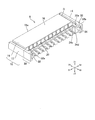
- FIG. 1 is a perspective view showing a connector of the present invention.
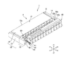
- FIG. 2 is a perspective view showing the housing shown in FIG.
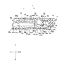
- FIG. 3 is a perspective view showing the actuator shown in FIG. 4 is a cross-sectional view of the connector shown in FIG. 1 taken along the line IV-IV.
- FIG. 5 is a cross-sectional view showing a state where the actuator of the connector shown in FIG. 4 is rotated.
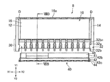
- FIG. 6 is a perspective view of the step of attaching the actuator to the housing as seen from the same direction as in FIG. 7A is a plan view of the housing and the actuator shown in FIG. 6 as viewed from above.
- 7B is a cross-sectional view of the housing and actuator shown in FIG. 7A taken along the line VIIB-VIIB.
- FIG. 1 is a perspective view showing a connector of the present invention.
- FIG. 2 is a perspective view showing the housing shown in FIG.
- FIG. 3 is a perspective view showing the actuator shown in FIG. 4 is a
- FIG. 8A is a plan view of the step of attaching the actuator to the housing as seen from the same direction as FIG. 7A.
- 8B is a cross-sectional view of the housing and the actuator shown in FIG. 8A taken along the line VIIIB-VIIIB.
- FIG. 9 is a partially enlarged view of the IX region of the actuator shown in FIG.
- FIG. 1 is a perspective view showing a connector 1 of the present invention
- FIG. 2 is a perspective view showing a housing 8 shown in FIG. 1
- FIG. 3 is a perspective view showing an actuator 40 shown in FIG. 4 is a cross-sectional view taken along the line IV-IV of the connector 1 shown in FIG. 1
- FIG. 5 is a cross-sectional view showing a state where the actuator 40 of the connector 1 shown in FIG. 4 is rotated.
- the connector 1 in the present embodiment is a connector into which a flat wire such as FPC or FFC can be inserted.
- the connector 1 includes a terminal 60, an actuator 40, and a housing 8 that houses the terminal 60. Details of each of these components will be described below.
- the direction in which the side surface of the housing 8 (side walls 12 and 14 of the storage unit 10 described later) is arranged in FIG. 1 is the left-right direction (X1, X2 direction), and the upper surface of the housing 8 (described later).
- the direction in which the top plate 16) is arranged is the upper direction (Z1 direction), the opposite side is the lower direction (Z2 direction), the direction in which the actuator 40 is arranged is the rear (Y2 direction), and the opposite side is the front (Y1 direction).
- the Y (Y1, Y2) direction and the X (X1, X2) direction are orthogonal to each other in plan view (angle viewed from the Z1 direction).
- the housing 8 is formed of an insulating material such as resin, and has a storage portion 10 for storing the terminal 60 and a left and right actuator holding portion 30 as shown in FIG.
- the storage unit 10 includes side walls 12 and 14 that form side surfaces of the housing 8 in the left-right direction (X1 and X2 directions), a top plate 16 that forms the top surface of the housing 8, and a housing 8 and a bottom portion 18 constituting the lower surface of 8.
- the housing 8 has left and right actuator holding portions 30 that extend from the left and right side walls 12 and 14 to the rear (Y2 direction) of the storage portion 10.
- the actuator holding unit 30 is a part that holds the actuator 40 between the left and right actuator holding units 30. As shown in FIG. 2, the actuator holding part 30 has a second temporary fixing part 32 and a second convex part 34 protruding to the actuator 40 side, and the detailed configuration thereof will be described. This will be described later for convenience.
- the housing 8 is provided with an opening 20 into which the terminal 60 is inserted in the rear (Y2 direction), and an opening 22 into which a flat electric wire (not shown) is inserted in the front (Y1 direction). Is provided.
- the actuator 40 is a member that elastically deforms the terminal 60, and is made of, for example, resin. As shown in FIGS. 2 and 4, the actuator 40 is disposed between the left and right actuator holding portions 30.
- the actuator 40 includes a cam portion 46, an operation portion 48, a hole portion 50 penetrating in the front-rear direction (Y1, Y2 direction), and the actuator holding portion 30 side (X1, X2 direction side). ) Projecting first temporary fixing portion 42 and first convex portion 44.
- first temporary fixing portion 42 and first convex portion 44 Projecting first temporary fixing portion 42 and first convex portion 44.
- the terminal 60 includes a base 62 extending in the vertical direction (Z1 and Z2 directions), a rod-shaped rear upper beam 64 extending rearward (Y2 direction) from the upper end 62a of the base 62, and the upper end of the base 62.
- a rod-shaped front upper beam 68 extending forward (Y1 direction) from 62a
- a rod-shaped rear lower beam 74 extending rearward (Y2 direction) from the lower end 62b of the base portion 62
- forward (Y1 direction) from the lower end 62b of the base portion 62 and forward (Y1 direction) from the lower end 62b of the base portion 62.
- a rod-like front and lower beam 78 extending.
- the base portion 62 is a portion that connects the upper beam (the rear upper beam 64 and the front upper beam 68) and the lower beam (the rear lower beam 74 and the front lower beam 78).
- the boundary between the base 62 and the upper beam (upper rear beam 64, front upper beam 68) (the upper end of the portion extending in the vertical direction of the base 62) is the upper end 62a, and the base 62 and the lower beam (rear lower beam 74).
- the lower boundary 62b (the lower end of the portion extending in the vertical direction of the base 62) is defined as the lower end 62b.
- a claw portion 63 protruding upward (Z1 direction) is formed above the base portion 62.
- the terminal 60 is fixed to the housing 8 by the claw 63 being hooked on the top plate 16 of the housing 8 as shown in FIG.
- the rear upper beam 64 is a portion pushed upward (Z1 direction) by the cam portion 46 of the actuator 40.
- the rear upper beam 64 is fitted in a hole 50 provided in the actuator 40.
- the rear lower beam 74 is positioned below the rear upper beam 64 (Z2 direction) and faces the rear upper beam 64 in the vertical direction (Z1, Z2 direction).
- the rear lower beam 74 includes a straight portion 74a, a lower surface 74b extending straight in the front-rear direction (Y1, Y2 direction), a convex stopper 75 protruding upward (Z1 direction), and an external not shown. And a fixing portion 76 fixed to the circuit board.
- the stopper 75 is provided behind the straight portion 74a (Y2 direction).
- the stopper 75 is positioned behind (in the Y2 direction) the cam portion 46 of the actuator 40, and the rear end (lower end) 46a of the cam portion 46 is positioned on the front surface 75a of the stopper 75.
- the fixing portion 76 is provided behind the stopper 75 (Y2 direction).
- the fixing portion 76 has a shape curved downward (Z2 direction) from the rear end 74a1 of the straight portion 74a, and the fixing portion 76 is located rearward (Y2 direction) with respect to the rear end 18b of the bottom portion 18 of the housing 8. Yes.
- the lower surface 76a of the fixed portion 76 is located below (Z2 direction) below the lower surface 18d of the bottom portion 18.
- the front surface 76b of the fixing portion 76 is located behind the rear end 18b of the bottom portion 18 (Y2 direction), and restricts the movement of the terminal portion 60 in the front direction (Y1 direction).
- the lower surface 76a of the fixing portion 76 is fixed on a circuit board (not shown) by solder.
- a gap C is preferably provided between the rear lower beam 74 and the upper surface 18 a of the bottom portion 18 of the housing 8. Specifically, if the lower surface of the rear lower beam 74 is the lower surface 74b and the upper surface of the bottom portion 18 below the rear lower beam 74 is the upper surface 18a1, the upper surface 18a1 of the bottom portion 18 and the lower surface of the rear lower beam 74 74b is separated. The size and position of the gap C will be described later for convenience of explanation.
- a cam portion 46 of the actuator 40 is disposed between the rear lower beam 74 and the rear upper beam 64.
- the cam portion 46 is a portion that pushes up the rear upper beam 64 upward (Z1 direction) by rotating between the rear upper beam 64 and the rear lower beam 74.
- action by rotation of the cam part 46 is mentioned later for convenience of explanation.
- the front upper beam 68 is a beam that inclines downward (Z2 direction) and contacts the flat electric wire when the rear upper beam 64 is pushed upward (Z1 direction).
- the front upper beam 68 has a contact point 68a protruding downward (Z2 direction).
- the contact point 68a comes into contact with the upper surface of the flat electric wire when a flat electric wire (not shown) is inserted into the housing 8 and the cam 46 pushes the rear upper beam 64 upward.
- the front lower beam 78 is a beam that sandwiches a flat electric wire between the front upper beam 68.
- the front lower beam 78 has a contact point 78a protruding upward (Z1 direction).
- the contact point 78 a comes into contact with the lower surface of the flat electric wire when a flat electric wire (not shown) is inserted into the housing 8.
- the lower surface 78b of the front lower beam 78 is in contact with the upper surface 18a of the bottom 18 of the housing 8.
- the front end of the lower surface 78b is a front end 78b1 and the front end of the front lower beam 78 is a front end 78c
- the front end 78b1 is located on the rear side (Y2 direction) with respect to the front end 78c, and the contact point 78a is behind the front end 78b1 (Y2). (Direction) side.
- the “front end 78b1” in the present embodiment indicates a front end of a portion of the lower surface 78b of the front lower beam 78 that is in contact with the upper surface 18a of the bottom portion 18. That is, the front end 78 b 1 is a boundary between a portion where the lower surface 78 b is in contact with the upper surface 18 a of the bottom portion 18 and a portion where the lower surface 78 b is separated from the upper surface 18 a of the bottom portion 18.
- the width from the rear end 46 a to the front end 46 b of the cam portion 46 is larger than the interval between the rear upper beam 64 and the rear lower beam 74. Therefore, when the cam portion 46 rotates with the rear end 46a as a fulcrum, the front end 46b moves upward (Z1 direction) and pushes the rear upper beam 64 upward (Z1 direction).
- the force that pushes the rear upper beam 64 upward is transmitted to the rear lower beam 74 via the base 62.
- the force that lifts the rear lower beam 74 upward (Z1 direction) is ahead of the fixing portion 76 (Y1 direction). ) Acts on the part.
- the rear lower beam 74 warps upward (Z1 direction) with the lower end 62b of the base portion 62 as an action point in a state where the lower surface 76a of the fixing portion 76 is fixed as a fulcrum.
- the rear upper beam 64 is pushed upward (Z1 direction) by the cam portion 46, whereby a counterclockwise moment (counterclockwise in FIGS. 4 and 5) is applied to the entire terminal 60.
- a counterclockwise moment counterclockwise in FIGS. 4 and 5
- the fixing portion 76 is fixed to a circuit board (not shown)
- the base portion 62 is inclined backward (Y2 direction).
- the front lower beam 78 and the rear lower beam 74 are bent (warped) upward (Z1 direction).
- the front (Y1) side of the front lower beam 78 is pushed downward (Z2 direction), and the front lower beam 78 has the front end 78b1 of the lower surface 78b as a fulcrum and the lower end 62b side of the base 62 is upward (Z1 direction). ) Is curved.
- the rear upper beam 64 is pushed upward (in the Z1 direction) by the cam portion 46, whereby the lower surface 62c of the lower end 62b of the base portion 62 is changed to the lower surface 78b of the front lower beam 78.
- the front end 78b1 and the rear lower beam 74 are curved so as to be positioned above the lower surface 76a of the fixing portion 76 (Z1 direction).
- the beam below the terminal 60 (the rear lower beam 74 and the front lower beam 78) is directed upward (Z1) with the front end 78b1 of the lower surface 78b of the front lower beam 78 and the fixing portion 76 of the rear lower beam 74 as fulcrums. To curve.
- the position of the portion of the rear lower beam 74 between the front end 78 b 1 of the lower surface 78 b and the fixing portion 76 of the rear lower beam 74 is higher than in the connector not having this configuration (in the Z1 direction).
- Side since the contact point 78a of the front lower beam 78 is located on the rear (Y2) side of the front end 78b1, this curvature causes the position of the contact point 78a to be on the upper side (Z1 direction) compared to the connector not having this configuration. It becomes.
- the distance between the contact point 78a of the front lower beam 78 of the connector 1 and the contact point 68a of the front upper beam 68 is smaller than that of the connector not having this configuration. For this reason, the contact pressure by the front upper beam 68 and the front lower beam 78 to the flat wire is increased, and the flat wire can be stably fixed by the connector 1.
- the connector 1 according to the present embodiment has such a configuration, so that the contact pressure to the flat electric wire can be maintained even if the connector 1 is downsized. For this reason, size reduction of the connector 1 is realizable.
- the lower surface 76 a of the fixing portion 76 of the rear lower beam 74 is fixed to a circuit board (not shown), and the connector 60 is fixed to the housing 8 by a claw portion 63. . Therefore, when the rear upper beam 64 is pushed upward (Z1 direction) and a counterclockwise moment (counterclockwise in FIGS. 4 and 5) acts on the entire terminal 60, this moment is applied to the claw portion 63 or the vicinity thereof. In the housing 8.
- the rear end 18b of the bottom portion 18 of the housing 8 is inclined so as to be located above (the Z1 direction) the front end 18c of the bottom portion 18 of the housing.
- the gap C is provided between the rear lower beam 74 and the upper surface 18a of the bottom portion 18 of the housing 8. Therefore, the inclination of the housing 8 is allowed by the gap C.
- the rear end of the gap C is a portion between the rear end 74a1 of the straight portion 74a of the rear lower beam 74 and the upper surface 18a1 of the bottom portion 18.
- the gap C has a curved portion of the rear lower beam 74. (A curved portion between the front surface 76b of the fixed portion 76 and the rear end 74a1 of the straight portion 74a) is not included. Therefore, the gap C is formed from the rear end 74a1 of the straight portion 74a to the front (Y1 direction side).
- the gap C only needs to be provided at least between the rear end 74a1 of the straight portion 74a and the upper surface 18a1 of the bottom portion 18.
- the force acting on the rear lower beam 74 and the front lower beam 78 via the base portion 62 is also increased. Furthermore, by providing the gap C, the restriction of the rear lower beam 74 to the curvature due to the rear end 74a1 of the rear lower beam 74 being in contact with the upper surface 18a1 of the bottom portion 18 is relaxed.
- the difference in height between the lower surface 62c of the lower end 62b of the base portion 62, the front end 78b1 of the lower surface 78b of the front lower beam 78, and the lower surface 76a of the fixing portion 76 of the rear lower beam 74 does not have this configuration. It becomes larger than the case of. That is, the front lower beam 78 and the rear lower beam 74 are greatly curved.
- the distance between the contact point 78a of the front lower beam 78 and the contact point 68a of the front upper beam 68 of the connector 1 is made smaller than that of the connector not having this configuration. be able to. For this reason, the flat electric wire can be stably fixed by the connector 1 and the connector 1 can be downsized.
- the gap C preferably extends at least from the front of the rear end 18 b of the bottom portion 18 of the housing to between the cam portion 46 and the lower end 62 b of the base portion 62. Since the gap C extends with such a length, the restriction on the inclination of the housing 8 is easily relaxed.
- the inclination of the housing 8 can be increased, and the curvature of the front upper beam 68, the rear upper beam 64, the front lower beam 78, and the rear lower beam 74 can be increased.
- the flat electric wire can be stably fixed by the connector 1 and the connector 1 can be downsized.
- the rear lower beam 74 extends rearward (Y2 direction) and downward (Z2 direction) from the base 62.
- the gap C is located behind the lower end 62b of the base portion 62 (Y2 direction). It is preferable to extend to the side.
- the front end of the gap C is located rearward (Y2 direction) with respect to the lower end 62b of the base 62 and closer to the lower end 62b.
- the inclination of the housing 8 can be maximized, and the curvature of the front upper beam 68, the rear upper beam 64, the front lower beam 78, and the rear lower beam 74 can be increased.
- the length of the gap C in the front-rear direction (Y1, Y2 direction) and the depth in the downward direction (Z2 direction) may be appropriately determined from the balance between the strength of the housing 8 and the desired bending width of each beam.
- each beam (the front lower beam 78 and the rear lower beam 74) is easily bent uniformly.
- the clearance gap C is comprised when the upper surface 18a of the bottom part 18 of the housing 8 is dented, as shown in FIG.
- the gap C is preferably configured by recessing the upper surface 18a of the bottom portion 18, but may be configured by recessing the lower surface 74b of the rear lower beam 74 upward (Z1 direction). .
- FIG. 6 is a perspective view of the step of attaching (assembling) the actuator 40 to the housing 8 as seen from the same direction as in FIG. 1, and FIG. 7A shows the housing 8 and the actuator 40 shown in FIG. 7B is a cross-sectional view taken along the line VIIB-VIIB of the housing 8 and the actuator 40 shown in FIG. 7A.
- FIG. 8A shows a process of attaching the actuator 40 to the housing 8 as shown in FIG. 7A.
- FIG. 8B is a cross-sectional view taken along the line VIIIB-VIIIB of the housing 8 and the actuator 40 shown in FIG. 8A
- FIG. 9 is a sectional view of the IX region of the actuator 40 shown in FIG. It is a partial enlarged view.
- the process of assembling the actuator 40 to the housing 8 includes the process of arranging the actuator 40 so that the cam portion 46 can pass between the stopper 75 and the rear upper beam 64, and the actuator 40 is moved forward (Y1 direction). And a step of causing. Further, by moving the actuator 40 moved forward (Y1 direction) downward (Z2 direction), the actuator 40 is fitted to the terminal 60 as shown in FIGS.
- action of each structure in each process are demonstrated one by one.
- a first temporary fixing portion 42 and a first convex portion 44 that protrude toward the actuator holding portion 30 side are provided. Is provided.
- the first temporary fixing portion 42 has a convex configuration that protrudes from the side surface 41 of the actuator 40 toward the actuator holding portion 30 (X1 direction side in FIG. 9).
- the first temporary fixing portion 42 is engaged with the second temporary fixing portion 32 of the actuator holding portion 30 in the process of assembling the actuator 40, thereby restricting the movement of the actuator 40 in the rear direction (Y2 direction).
- the angle formed by the front surface 42b and the side surface 41 is as follows.
- the angle formed by the rear surface 42a and the side surface 41 is preferably smaller.
- the angle formed by the front surface 42b and the side surface 41 is an acute angle.
- the first convex portion 44 is provided below (the Z2 direction) side of the first temporary fixing portion 42.
- the first convex portion 44 is a portion that engages with the second convex portion 34 of the actuator holding portion 30.
- the first convex portion 44 has a convex configuration that protrudes from the side surface 41 of the actuator 40 toward the actuator holding portion 30.
- the surface 44c on the actuator holding portion 30 side of the first convex portion 44 (the surface on the X1 direction side in FIG. 9) is more than the surface 42c on the actuator holding portion 30 side of the first temporary fixing portion 42. Located on the side.
- the angle between the upper surface 44d and the surface 42c of the first temporary fixing portion 42 is preferably closer to the vertical.
- the actuator holding portion 30 has a side surface on the actuator 40 side that includes a second temporary fixing portion 32 that protrudes toward the actuator 40 and a second convex portion 34. Is provided.
- the second temporary fixing portion 32 has a convex configuration protruding from the actuator holding portion 30 toward the actuator 40.
- the second temporary fixing portion 32 restricts the movement of the actuator 40 in the rear direction (Y2 direction) by hooking on the first temporary fixing portion 42 of the actuator 40 in the process of assembling the actuator 40 to the connector. Part.
- the front end of the second temporary fixing portion 32 on the Y1 direction side is a front end (front surface) 32a, and the side surface behind (Y2 direction) the front end 32a is a slope 32b, the slope 32b And the side walls 12 and 14 are preferably acute when the housing 8 is viewed from above (Z1 direction).
- the actuator 40 is moved in the direction of the arrow (Y1 direction).
- the rear end (rear surface) 42 a of the first temporary fixing part 42 is arranged in front of the front end (front surface) 32 a of the second temporary fixing part 32 (Y1 direction).
- the cam portion 46 is disposed forward (Y1 direction) and above (Z1 direction) and below the rear upper beam 64 (Z2 direction) with respect to the stopper 75 of the terminal 60.
- the interval between the inclined surfaces 32b of the left and right second temporary fixing portions 32 is smaller than the interval between the left and right surfaces 42c of the first temporary fixing portion 42.
- the inclined surface 32b of the temporary fixing part 32 and the front surface 42b of the first temporary fixing part 42 are in contact with each other (a state in which contact pressure is maintained).
- the actuator 40 has the first temporary fixing portion 42. 42 enters the inclined surface 32b of the second temporary fixing portion 32. During this movement, the actuator 40 may be bent by applying a contact pressure between the second temporary fixing portion 32 and the first temporary fixing portion 42.
- the rear end 42a of the first temporary fixing portion 42 moves forward (Y1 direction) relative to the front end 32a of the second temporary fixing portion 32, so that the second Since the inclined surface 32b of the temporary fixing portion 32 and the front surface 42b of the first temporary fixing portion 42 are separated, the contact pressure applied to the actuator 40 is lost.
- the width in the left-right direction (X1, X2 direction) of the actuator 40 returns to the width before the contact pressure is applied, and the surface 42c on the actuator holding portion 30 side of the first temporary fixing portion 42 is It is on the outer side (X1, X2 direction side) than the rear end 32b1 of the inclined surface 32b of the temporary fixing portion 32.
- the rear end 42a of the first temporary fixing portion 42 and the front end 32a of the second temporary fixing portion 32 are in the front-rear direction (Y1, the plane viewed from the Z1 direction).
- Y2 direction is at least partially overlapped, and movement of the first temporary fixing portion 42 in the rear (Y2 direction) is restricted.
- the connector 1 according to the present embodiment is located behind the first temporary fixing portion 42 (Y2) when the first temporary fixing portion 42 is in front of the second temporary fixing portion 32 (Y1 direction). Directional movement is restricted.
- the connector 1 in the present embodiment is located in front of the second temporary fixing portion 32 (Y1 direction) from the front end 16a of the top plate 16 to the front end of the second temporary fixing portion 32.
- a groove D extending in the front-rear direction (Y1, Y2 direction) up to 32a is formed.
- the groove D is a recess provided when the second temporary fixing portion 32 is formed.
- the second temporary fixing part 32 is formed by arranging a mold (not shown) in accordance with a desired position of the front end 32a of the second temporary fixing part 32 when the housing 8 is molded. At this time, since the rear end of the mold (the end on the Y2 direction side in the drawing) is arranged in accordance with the position of the front end 32a, the molded top plate 16 has a top plate corresponding to the position of the mold. A groove D extending in the front-rear direction from the front end 16 a of 16 to the front end 32 a of the second temporary fixing portion 32 is formed.
- the groove D is formed in this manner, so that the front end 32a of the second temporary fixing portion 32 can be seen inside the groove D when the top plate 16 is viewed from the front (Y1 direction).
- the connector 1 according to the present embodiment has such a configuration, so that the second temporary fixing portion 32 is formed by a mold that forms the front end 32a of the second temporary fixing portion 32, and the second temporary fixing portion 32. It can be formed by two molds that form the inclined surface 32b. Conventionally, in order to form the temporary fixing portion in the housing 8, at least three or more dies are required. On the other hand, in the connector 1 of this embodiment, by having the above-described configuration, it is possible to simplify the types of molds required and the steps in forming the configuration required for temporary fixing. For this reason, the expense in formation of the connector 1 can be held down.
- the connector 1 in this embodiment can form the 2nd temporary fix
- stop part 32 can be formed using the metal mold
- die can be simplified.
- the second temporary fixing portion 32 is integrally formed with the top plate 16, for example, the second temporary fixing portion 32 is compared with a connector in which a bar-like or convex temporary fixing portion is separately formed. The strength of the stopper 32 can be increased.
- the cam portion 46 In order to arrange the cam portion 46 in front of the stopper 75 (Y1 direction), the cam portion 46 is positioned between the stopper 75 of the terminal 60 and the rear upper beam 64 as shown in FIGS. 8A and 8B. 4, the actuator 40 is pushed down (Z2 direction) until the rear end 46a of the cam portion 46 is positioned on the front surface 75a of the stopper 75.
- the distance between the left and right second protrusions 34 is smaller than the distance between the surfaces 44c of the left and right first protrusions 44.
- the surface 44c of the first convex portion 44 comes into contact (a state where the contact pressure is maintained).
- the upper surface 44d of the first convex portion 44 moves downward (in the Z2 direction) below the lower surface 34d of the second convex portion 34, whereby the first convex portion 44 is moved. Since the surface 44c of the portion 44 is separated from the surface 34c of the second convex portion 34 on the actuator 40 side, the contact pressure applied to the actuator 40 is lost.
- the width in the left-right direction (X1, X2 direction) of the actuator 40 returns to the width before the contact pressure is applied, and the surface 44c on the actuator holding portion 30 side of the first convex portion 44 is the second convex portion. It is on the outer side (X1, X2 direction side) than the surface 34c of the part 34. Therefore, at least a part of the upper surface 44d of the first convex portion 44 and the lower surface 34d of the second convex portion 34 overlap in the vertical direction (Z1, Z2 direction) as shown in FIG.
- the upward movement (Z1 direction) of the actuator 40 is restricted by the first protrusion 44 engaging the second protrusion 34 of the actuator holding section 30. .
- the connector 1 in this embodiment does not require a part for preventing displacement from the fixed position of the actuator 40, unlike a connector not having this configuration. For this reason, simplification of the structure of the connector 1 is realizable. Further, since the configuration of the connector 1 can be simplified, a process of separately attaching a part for holding the actuator 40 and the cost of the part are not required.
- the positions of the first temporary fixing portion 42 and the second temporary fixing portion 32 are not limited to the positions shown in FIGS. 2 and 6 to 9, and can be appropriately adjusted according to the desired position of the cam portion 46. it can.
- the position of the second temporary fixing portion 32 can be adjusted by the depth of the groove D.
- first temporary fixing portion 42 and the second temporary fixing portion 32 are not limited to the convex configuration, and one may be a concave configuration as long as they are engaged with each other.
- the actuator holding unit 30 may not have a convex configuration.
- the engaging portion of the actuator holding portion 30 and the actuator 40 may be configured so that the steps are engaged with each other, and instead of the convex first convex portion 44 and the second convex portion 34, A convex configuration and a concave configuration may be engaged.
- the positions of the first convex portion 44 and the second convex portion 34 are not limited to the positions shown in the drawing, and can be appropriately adjusted according to the desired position of the cam portion 46.
- the vertical width of the second convex portion 34 can be appropriately adjusted according to the desired position of the cam portion 46.
- the configuration of the terminal 60 is not limited to the configuration shown in FIGS. However, other configurations may be used.
- the terminal 60 may be configured to include a fixing portion for fixing the front lower beam 78 to a circuit board (not shown) outside the connector 1.
Landscapes
- Coupling Device And Connection With Printed Circuit (AREA)
- Details Of Connecting Devices For Male And Female Coupling (AREA)
Abstract
Description
Claims (8)
- 端子とアクチュエーターと前記端子を収納するハウジングとを有する、平型電線が挿入可能なコネクタであって、
前記端子は、
上下方向に延びる基部と、
前記基部の上端から後方に延びる後上ビームと、
前記後上ビームが上方に押し上げられることにより下方に傾いて前記平型電線に接触する、前記基部の上端から前方に延びる前上ビームと、
前記基部の下端から後方に延びる後下ビームと、
前記基部の下端から前方に延びる前下ビームと、
を備え、
前記アクチュエーターは、前記後下ビームと前記後上ビームとの間に配置されて前記後上ビームを上方に押し上げるカム部を含み、
前記後下ビームは、前記後下ビームの後端に、外部の回路基板に固定するための固定部を含み、
前記前下ビームは、
前記平型電線に接触する、上方に突出した接触点と、
前記ハウジングの底部の上面に接触する前下ビームの下面の前端と、
を含み、
前記接触点は、前記前下ビームの下面の前端よりも後方側に位置し、
前記前下ビームと前記後下ビームは、前記後上ビームが上方に押し上げられることにより、前記前下ビームの下面の前端と前記固定部を支点として上方に湾曲する、
ことを特徴とするコネクタ。 - 請求項1に記載のコネクタであって、
前記ハウジングは、前記後上ビームが上方に押し上げられることにより、前記ハウジングの底部の後端が、前記ハウシングの底部の前端よりも上方に位置するように傾斜し、
前記ハウジングの底部の上面後端と前記後下ビームとの間に、前記ハウジングの傾斜を許容する隙間が設けられている、
ことを特徴とするコネクタ。 - 請求項2に記載のコネクタであって、
前記隙間が、少なくとも前記ハウジングの底部の後端から、前記カムと前記基部の下端の間まで延びている、
ことを特徴とするコネクタ。 - 請求項2または請求項3に記載のコネクタであって、
前記隙間が、前記ハウジングの底部の上面が凹んでいることにより構成されている、
ことを特徴とするコネクタ。 - ハウジングと、
前記ハウジング内に収納される端子と、
アクチュエーターと、
を備え、
前記ハウジングは、
前記端子を収納する、前記ハウジングの左右の側面を構成する左右の側壁と前記ハウジングの上面を構成する天板とを有する収納部と、
前記左右の側壁から前記収納部の後方へそれぞれ延びる左右のアクチュエーター保持部と、
を含み、
前記端子は、
後方に延びる後上ビームと、
前記後上ビームの下方に位置して後方に延びる、上方に突出する凸状のストッパーを有する後下ビームと、
を含み、
前記アクチュエーターは、
前記左右アクチュエーター保持部の間に配置され、
前記後下ビームと前記後上ビームとの間に配置されるカム部と前記左右のアクチュエーター保持部側に突出する左右の第1の仮止め部とを含み、
前記アクチュエーター保持部は、前記アクチュエーター側に突出する第2の仮止め部を含み、
前記第2の仮止め部は、前記第1の仮止め部が前記第2の仮止め部の前方にあるときに、前記第1の仮止め部の後方向への動きを規制し、
前記第2の仮止め部の前方に、前記天板の前端から前記第2の仮止め部の前端まで延びる溝が形成されている、
ことを特徴とするコネクタ。 - 請求項5に記載のコネクタであって、
前記天板を前方から見た場合に、前記溝の内側に前記第2の仮止め部の前端が見えることを特徴とするコネクタ。 - ハウジングと、
前記ハウジング内に収納される端子と、
アクチュエーターと、
を備え、
前記ハウジングは、
前記端子を収納する、前記ハウジングの左右の側面を構成する左右の側壁と前記ハウジングの上面を構成する天板とを有する収納部と、
前記左右の側壁から前記収納部の後方へそれぞれ延びる左右のアクチュエーター保持部と、
を含み、
前記端子は、
後方に延びる後上ビームと、
前記後上ビームの下方に位置して後方に延びる、上方に突出する凸状のストッパーを有する後下ビームと、
を含み、
前記アクチュエーターは、
前記後下ビームと前記後上ビームの間の、前記ストッパーの前方に配置されるカム部を含み、
前記左右アクチュエーター保持部の間に配置されて、前記アクチュエーター保持部により上方向の動きが規制される、
ことを特徴とするコネクタ。 - 請求項7に記載のコネクタであって、
前記アクチュエーターが、前記アクチュエーター保持部側に突出する第1の凸部を含み、
前記アクチュエーター保持部が、前記アクチュエーター側に突出する第2の凸部を含み、
前記第1の凸部が前記第2の凸部に係合することにより、前記アクチュエーターの上方向の動きが規制される、
ことを特徴とするコネクタ。
Priority Applications (3)
| Application Number | Priority Date | Filing Date | Title |
|---|---|---|---|
| KR1020167019949A KR101832645B1 (ko) | 2013-12-27 | 2014-12-26 | 커넥터 |
| US15/037,014 US9698510B2 (en) | 2013-12-27 | 2014-12-26 | Connector for securing a flat cable |
| CN201480061869.5A CN105723573B (zh) | 2013-12-27 | 2014-12-26 | 连接器 |
Applications Claiming Priority (2)
| Application Number | Priority Date | Filing Date | Title |
|---|---|---|---|
| JP2013273021A JP6208008B2 (ja) | 2013-12-27 | 2013-12-27 | コネクタ |
| JP2013-273021 | 2013-12-27 |
Publications (1)
| Publication Number | Publication Date |
|---|---|
| WO2015099117A1 true WO2015099117A1 (ja) | 2015-07-02 |
Family
ID=53478956
Family Applications (1)
| Application Number | Title | Priority Date | Filing Date |
|---|---|---|---|
| PCT/JP2014/084491 Ceased WO2015099117A1 (ja) | 2013-12-27 | 2014-12-26 | コネクタ |
Country Status (6)
| Country | Link |
|---|---|
| US (1) | US9698510B2 (ja) |
| JP (1) | JP6208008B2 (ja) |
| KR (1) | KR101832645B1 (ja) |
| CN (1) | CN105723573B (ja) |
| TW (1) | TWI589064B (ja) |
| WO (1) | WO2015099117A1 (ja) |
Families Citing this family (6)
| Publication number | Priority date | Publication date | Assignee | Title |
|---|---|---|---|---|
| JP6780352B2 (ja) * | 2016-08-04 | 2020-11-04 | I−Pex株式会社 | 電気コネクタ |
| JP2020107507A (ja) * | 2018-12-27 | 2020-07-09 | モレックス エルエルシー | コネクタ組立体 |
| JP7560966B2 (ja) * | 2020-06-08 | 2024-10-03 | モレックス エルエルシー | ケーブル端子及びコネクタ |
| CN111834771B (zh) * | 2020-06-20 | 2021-11-30 | 青岛恩利旺精密工业有限公司 | 一种fpc连接器及其连接方法 |
| US20220407271A1 (en) * | 2021-06-18 | 2022-12-22 | Lear Corporation | Electrical Connector Housing and Electrical Connector Assembly for Electrically Conductive Structures |
| JP7497127B2 (ja) * | 2021-07-30 | 2024-06-10 | ヒロセ電機株式会社 | 平型導体用電気コネクタ |
Citations (2)
| Publication number | Priority date | Publication date | Assignee | Title |
|---|---|---|---|---|
| JPH09283236A (ja) * | 1996-04-09 | 1997-10-31 | Sumitomo Wiring Syst Ltd | フレキシブルプリント基板用コネクタ |
| JP4576349B2 (ja) * | 2006-03-24 | 2010-11-04 | ヒロセ電機株式会社 | 平型回路基板用電気コネクタ |
Family Cites Families (13)
| Publication number | Priority date | Publication date | Assignee | Title |
|---|---|---|---|---|
| JP3047862B2 (ja) | 1997-07-08 | 2000-06-05 | オムロン株式会社 | コネクタ |
| TW443641U (en) | 2000-02-02 | 2001-06-23 | Hon Hai Prec Ind Co Ltd | Electrical connector |
| JP4054741B2 (ja) * | 2003-09-26 | 2008-03-05 | 日本圧着端子製造株式会社 | 低背型fpc用zifコネクタ |
| JP4578931B2 (ja) * | 2004-10-18 | 2010-11-10 | 第一電子工業株式会社 | コネクタ |
| JP4437982B2 (ja) * | 2005-08-08 | 2010-03-24 | ヒロセ電機株式会社 | 平型ケーブル用電気コネクタ |
| JP4858249B2 (ja) * | 2007-03-19 | 2012-01-18 | オムロン株式会社 | コネクタ |
| JP4330084B2 (ja) * | 2007-06-12 | 2009-09-09 | ヒロセ電機株式会社 | 平型導体用電気コネクタ |
| JP4992707B2 (ja) * | 2007-12-28 | 2012-08-08 | オムロン株式会社 | コネクタ |
| JP5498733B2 (ja) * | 2009-07-16 | 2014-05-21 | モレックス インコーポレイテド | コネクタ |
| JP5739104B2 (ja) | 2010-01-29 | 2015-06-24 | モレックス インコーポレイテドMolex Incorporated | コネクタ |
| JP5123976B2 (ja) | 2010-04-08 | 2013-01-23 | パナソニック株式会社 | コネクタ |
| JP4897917B1 (ja) | 2010-09-03 | 2012-03-14 | 京セラエルコ株式会社 | コネクタ |
| JP4945006B1 (ja) * | 2011-09-26 | 2012-06-06 | イリソ電子工業株式会社 | コネクタ |
-
2013
- 2013-12-27 JP JP2013273021A patent/JP6208008B2/ja active Active
-
2014
- 2014-12-25 TW TW103145500A patent/TWI589064B/zh not_active IP Right Cessation
- 2014-12-26 US US15/037,014 patent/US9698510B2/en not_active Expired - Fee Related
- 2014-12-26 WO PCT/JP2014/084491 patent/WO2015099117A1/ja not_active Ceased
- 2014-12-26 CN CN201480061869.5A patent/CN105723573B/zh active Active
- 2014-12-26 KR KR1020167019949A patent/KR101832645B1/ko active Active
Patent Citations (2)
| Publication number | Priority date | Publication date | Assignee | Title |
|---|---|---|---|---|
| JPH09283236A (ja) * | 1996-04-09 | 1997-10-31 | Sumitomo Wiring Syst Ltd | フレキシブルプリント基板用コネクタ |
| JP4576349B2 (ja) * | 2006-03-24 | 2010-11-04 | ヒロセ電機株式会社 | 平型回路基板用電気コネクタ |
Also Published As
| Publication number | Publication date |
|---|---|
| CN105723573B (zh) | 2018-02-16 |
| TW201541725A (zh) | 2015-11-01 |
| US20160301151A1 (en) | 2016-10-13 |
| US9698510B2 (en) | 2017-07-04 |
| JP2015128010A (ja) | 2015-07-09 |
| KR101832645B1 (ko) | 2018-02-26 |
| KR20160102502A (ko) | 2016-08-30 |
| JP6208008B2 (ja) | 2017-10-04 |
| CN105723573A (zh) | 2016-06-29 |
| TWI589064B (zh) | 2017-06-21 |
Similar Documents
| Publication | Publication Date | Title |
|---|---|---|
| JP6208008B2 (ja) | コネクタ | |
| JP5603790B2 (ja) | フローティング型コネクタ | |
| JP5765462B1 (ja) | 電気コネクタ | |
| US7789698B2 (en) | Connector for flat terminal | |
| KR101226418B1 (ko) | 단자 피팅 | |
| JP2008310964A (ja) | 平型導体用電気コネクタ | |
| JP2008130244A (ja) | コネクタ | |
| JP4989741B2 (ja) | 回路基板用電気コネクタ | |
| JP2011023236A (ja) | コネクタ | |
| KR20110098645A (ko) | 회로 기판용 전기 커넥터 | |
| JP6686140B2 (ja) | コネクタ | |
| KR101668914B1 (ko) | 평형 도체용 전기 커넥터 | |
| JP6533151B2 (ja) | コネクタ | |
| JP5186289B2 (ja) | ワイヤハーネス保持クリップ | |
| JP6928506B2 (ja) | コネクタホルダ | |
| JP6861582B2 (ja) | コネクタ | |
| JP4684191B2 (ja) | コネクタ | |
| JP7087986B2 (ja) | 分割コネクタ | |
| JP5734132B2 (ja) | コネクタ | |
| JP6680189B2 (ja) | 電線カバー及びコネクタ | |
| JP7368069B2 (ja) | コネクタ | |
| JP4808537B2 (ja) | ディップコネクタ | |
| JP2011018567A (ja) | コネクタ | |
| JP7300890B2 (ja) | 端子台 | |
| JP4161137B2 (ja) | Fpc用コネクタ |
Legal Events
| Date | Code | Title | Description |
|---|---|---|---|
| 121 | Ep: the epo has been informed by wipo that ep was designated in this application |
Ref document number: 14874906 Country of ref document: EP Kind code of ref document: A1 |
|
| WWE | Wipo information: entry into national phase |
Ref document number: 15037014 Country of ref document: US |
|
| NENP | Non-entry into the national phase |
Ref country code: DE |
|
| ENP | Entry into the national phase |
Ref document number: 20167019949 Country of ref document: KR Kind code of ref document: A |
|
| 122 | Ep: pct application non-entry in european phase |
Ref document number: 14874906 Country of ref document: EP Kind code of ref document: A1 |