WO2015087746A1 - メッシュフィルタ - Google Patents
メッシュフィルタ Download PDFInfo
- Publication number
- WO2015087746A1 WO2015087746A1 PCT/JP2014/081928 JP2014081928W WO2015087746A1 WO 2015087746 A1 WO2015087746 A1 WO 2015087746A1 JP 2014081928 W JP2014081928 W JP 2014081928W WO 2015087746 A1 WO2015087746 A1 WO 2015087746A1
- Authority
- WO
- WIPO (PCT)
- Prior art keywords
- filter
- mesh filter
- rib
- ribs
- inner cylinder
- Prior art date
Links
- 229920005989 resin Polymers 0.000 claims abstract description 14
- 239000011347 resin Substances 0.000 claims abstract description 14
- 238000001746 injection moulding Methods 0.000 claims description 25
- 230000002093 peripheral effect Effects 0.000 claims description 12
- 239000012530 fluid Substances 0.000 claims description 10
- 229920005992 thermoplastic resin Polymers 0.000 claims description 9
- 239000000126 substance Substances 0.000 claims description 4
- 239000000446 fuel Substances 0.000 description 19
- 230000000052 comparative effect Effects 0.000 description 16
- 238000001914 filtration Methods 0.000 description 13
- 238000010586 diagram Methods 0.000 description 11
- 238000002347 injection Methods 0.000 description 8
- 239000007924 injection Substances 0.000 description 8
- 239000002184 metal Substances 0.000 description 7
- 238000000465 moulding Methods 0.000 description 7
- 239000002245 particle Substances 0.000 description 6
- 230000013011 mating Effects 0.000 description 5
- 238000000034 method Methods 0.000 description 5
- 238000012986 modification Methods 0.000 description 4
- 230000004048 modification Effects 0.000 description 4
- 229920006324 polyoxymethylene Polymers 0.000 description 4
- 239000012085 test solution Substances 0.000 description 4
- 239000011324 bead Substances 0.000 description 3
- 238000004140 cleaning Methods 0.000 description 3
- 239000011521 glass Substances 0.000 description 3
- 229920001778 nylon Polymers 0.000 description 3
- XLYOFNOQVPJJNP-UHFFFAOYSA-N water Substances O XLYOFNOQVPJJNP-UHFFFAOYSA-N 0.000 description 3
- 239000004677 Nylon Substances 0.000 description 2
- 229930182556 Polyacetal Natural products 0.000 description 2
- 230000007423 decrease Effects 0.000 description 2
- 239000000835 fiber Substances 0.000 description 2
- 238000005461 lubrication Methods 0.000 description 2
- 239000000463 material Substances 0.000 description 2
- 238000005259 measurement Methods 0.000 description 2
- NJPPVKZQTLUDBO-UHFFFAOYSA-N novaluron Chemical compound C1=C(Cl)C(OC(F)(F)C(OC(F)(F)F)F)=CC=C1NC(=O)NC(=O)C1=C(F)C=CC=C1F NJPPVKZQTLUDBO-UHFFFAOYSA-N 0.000 description 2
- 229920003002 synthetic resin Polymers 0.000 description 2
- 239000000057 synthetic resin Substances 0.000 description 2
- 238000011144 upstream manufacturing Methods 0.000 description 2
- 239000000428 dust Substances 0.000 description 1
- 230000000694 effects Effects 0.000 description 1
- 238000005516 engineering process Methods 0.000 description 1
- 238000009940 knitting Methods 0.000 description 1
- 239000007788 liquid Substances 0.000 description 1
- 238000004519 manufacturing process Methods 0.000 description 1
- 239000000203 mixture Substances 0.000 description 1
- 239000000843 powder Substances 0.000 description 1
- 238000003825 pressing Methods 0.000 description 1
- 238000007493 shaping process Methods 0.000 description 1
- 239000002904 solvent Substances 0.000 description 1
- 229920001187 thermosetting polymer Polymers 0.000 description 1
Images


Classifications
-
- B—PERFORMING OPERATIONS; TRANSPORTING
- B01—PHYSICAL OR CHEMICAL PROCESSES OR APPARATUS IN GENERAL
- B01D—SEPARATION
- B01D29/00—Filters with filtering elements stationary during filtration, e.g. pressure or suction filters, not covered by groups B01D24/00 - B01D27/00; Filtering elements therefor
- B01D29/01—Filters with filtering elements stationary during filtration, e.g. pressure or suction filters, not covered by groups B01D24/00 - B01D27/00; Filtering elements therefor with flat filtering elements
- B01D29/012—Making filtering elements
-
- B—PERFORMING OPERATIONS; TRANSPORTING
- B01—PHYSICAL OR CHEMICAL PROCESSES OR APPARATUS IN GENERAL
- B01D—SEPARATION
- B01D29/00—Filters with filtering elements stationary during filtration, e.g. pressure or suction filters, not covered by groups B01D24/00 - B01D27/00; Filtering elements therefor
- B01D29/01—Filters with filtering elements stationary during filtration, e.g. pressure or suction filters, not covered by groups B01D24/00 - B01D27/00; Filtering elements therefor with flat filtering elements
- B01D29/03—Filters with filtering elements stationary during filtration, e.g. pressure or suction filters, not covered by groups B01D24/00 - B01D27/00; Filtering elements therefor with flat filtering elements self-supporting
-
- B—PERFORMING OPERATIONS; TRANSPORTING
- B29—WORKING OF PLASTICS; WORKING OF SUBSTANCES IN A PLASTIC STATE IN GENERAL
- B29C—SHAPING OR JOINING OF PLASTICS; SHAPING OF MATERIAL IN A PLASTIC STATE, NOT OTHERWISE PROVIDED FOR; AFTER-TREATMENT OF THE SHAPED PRODUCTS, e.g. REPAIRING
- B29C45/00—Injection moulding, i.e. forcing the required volume of moulding material through a nozzle into a closed mould; Apparatus therefor
- B29C45/17—Component parts, details or accessories; Auxiliary operations
- B29C45/26—Moulds
- B29C45/2628—Moulds with mould parts forming holes in or through the moulded article, e.g. for bearing cages
-
- B—PERFORMING OPERATIONS; TRANSPORTING
- B29—WORKING OF PLASTICS; WORKING OF SUBSTANCES IN A PLASTIC STATE IN GENERAL
- B29C—SHAPING OR JOINING OF PLASTICS; SHAPING OF MATERIAL IN A PLASTIC STATE, NOT OTHERWISE PROVIDED FOR; AFTER-TREATMENT OF THE SHAPED PRODUCTS, e.g. REPAIRING
- B29C45/00—Injection moulding, i.e. forcing the required volume of moulding material through a nozzle into a closed mould; Apparatus therefor
- B29C45/17—Component parts, details or accessories; Auxiliary operations
- B29C45/26—Moulds
- B29C45/263—Moulds with mould wall parts provided with fine grooves or impressions, e.g. for record discs
-
- B—PERFORMING OPERATIONS; TRANSPORTING
- B01—PHYSICAL OR CHEMICAL PROCESSES OR APPARATUS IN GENERAL
- B01D—SEPARATION
- B01D2201/00—Details relating to filtering apparatus
- B01D2201/04—Supports for the filtering elements
- B01D2201/0415—Details of supporting structures
-
- B—PERFORMING OPERATIONS; TRANSPORTING
- B29—WORKING OF PLASTICS; WORKING OF SUBSTANCES IN A PLASTIC STATE IN GENERAL
- B29K—INDEXING SCHEME ASSOCIATED WITH SUBCLASSES B29B, B29C OR B29D, RELATING TO MOULDING MATERIALS OR TO MATERIALS FOR MOULDS, REINFORCEMENTS, FILLERS OR PREFORMED PARTS, e.g. INSERTS
- B29K2059/00—Use of polyacetals, e.g. POM, i.e. polyoxymethylene or derivatives thereof, as moulding material
-
- B—PERFORMING OPERATIONS; TRANSPORTING
- B29—WORKING OF PLASTICS; WORKING OF SUBSTANCES IN A PLASTIC STATE IN GENERAL
- B29K—INDEXING SCHEME ASSOCIATED WITH SUBCLASSES B29B, B29C OR B29D, RELATING TO MOULDING MATERIALS OR TO MATERIALS FOR MOULDS, REINFORCEMENTS, FILLERS OR PREFORMED PARTS, e.g. INSERTS
- B29K2905/00—Use of metals, their alloys or their compounds, as mould material
-
- B—PERFORMING OPERATIONS; TRANSPORTING
- B29—WORKING OF PLASTICS; WORKING OF SUBSTANCES IN A PLASTIC STATE IN GENERAL
- B29L—INDEXING SCHEME ASSOCIATED WITH SUBCLASS B29C, RELATING TO PARTICULAR ARTICLES
- B29L2031/00—Other particular articles
- B29L2031/14—Filters
Definitions
- This invention relates to a mesh filter used for filtering out foreign substances in a fluid, and more particularly to a mesh filter integrally formed by injection molding.
- a mesh filter is disposed in the middle of an oil pipe such as a fuel supply pipe or a lubrication device connected to a fuel injection device of an automobile, and foreign matters in a fluid such as fuel and oil are filtered by the mesh filter. ing.
- FIG. 12 is a diagram showing a mesh filter 100 of the first conventional example.
- 12A is a plan view of the mesh filter 100 of the first conventional example
- FIG. 12B is a cross-sectional view of the mesh filter 100 cut along the line A10-A10 in FIG. 12A.
- FIG. FIG. 12C is a cross-sectional view of the mold 101 for explaining the first stage in the forming method of the mesh filter 100 of the first conventional example
- FIG. 12D is the mesh filter of the first conventional example.
- FIG.12 (e) is an enlarged view of B11 part of Fig.12 (a).
- the mesh filter 100 of the first conventional example shown in FIG. 12 is an opening through which oil can pass and foreign matter (metal powder, dust, etc.) having a predetermined size (for example, a diameter of 0.1 mm) can be filtered.
- the mesh filter 100 has a shape in which a mesh member 103 is stretched over a frame member 104 (see FIGS. 12A to 12B and 12E).
- Such a mesh filter 100 of the first conventional example is insert-molded as shown in FIGS. 12 (c) to 12 (d).
- the mesh member 103 is disposed on the pedestal portion 108 in the cavity 107 of the first mold 105 (FIG. 12C).
- the second mold 106 is pressed against the first mold 105 (the first mold 105 and the second mold 106 are clamped), and the pressing portion 110 of the second mold 106 and the first mold 105 are pressed.
- the mesh filter 100 of the first conventional example is manufactured by insert molding, the mesh member 103 is accommodated in a predetermined position of the cavity 107 as compared with the case where the whole is integrally molded by injection molding.
- the manufacturing man-hours increased as much as the process to do was required.
- FIG. 13 is a view showing a mesh filter 200 according to a second conventional example, and is a view showing an injection molded mesh filter 200.
- the mesh filter 200 shown in FIG. 13 since the frame body portion 201 and the filter portion 202 are integrally formed by injection molding, there is no problem like the mesh filter 100 of the first conventional example (Patent Document 3). , 4).
- Japanese Utility Model Publication No. 5-44204 JP 2007-1232 A Japanese Patent Laid-Open No. 7-100317 (see especially paragraph 0008) Japanese Patent Laid-Open No. 7-156156 (especially, see paragraph 0008)
- the opening area of the filter unit 202 is small, so the pressure loss of the fluid passing through the filter unit 202 is large. Therefore, there is a problem that the filter performance is lowered.
- the filter part 202 is formed such that the rib interval of the horizontal ribs 204 changes sparsely and densely with respect to the rib interval (dense) of the vertical ribs 203. Since variations occur in the shape and opening area of the opening portion, foreign matter in a fluid having a size to be filtered cannot be filtered out, and the filter performance is deteriorated.
- an object of the present invention is to provide an injection-molded mesh filter that can improve the productivity while maintaining the required filter performance and can reduce the product price.
- the mesh filter 1 according to the present invention is used for filtering out foreign substances in the fluid.
- the mesh filter 1 according to the present invention includes a gate connection portion 2 and 26 in which gates 18 and 28 for injection molding are disposed, an outer cylinder 3 surrounding the gate connection portion 2 and 26, and the gate connection portion 2 and 26.
- the filter part 4 which connects the outer peripheral surfaces 2a and 26a and the inner peripheral surface 3a of the outer cylinder 3 along the radial direction of the gate connecting parts 2 and 26 is provided.
- the filter unit 4 is formed along the XY plane when a virtual plane perpendicular to the central axes 5 and 27 of the gate connection units 2 and 26 is defined as an XY plane.
- a plurality of portions other than the connection portion with the gate connection portions 2 and 26 and the connection portion with the outer cylinder 3 in the filter portion 4 are formed in parallel and at equal intervals along the XY plane.
- the vertical rib 6 is disposed on either the front side or the back side of the filter unit 4.
- the lateral rib 7 is disposed on either the front side or the back side of the filter unit 4.
- the opening 8 is formed at the intersection of the vertical groove 6 a between the adjacent vertical ribs 6, 6 and the horizontal groove 7 a between the adjacent horizontal ribs 7, 7. Then, molten resin is injected into the cavity portion from the gates 18 and 28 that open to the cavity portion (first cavity portion 14) that forms the gate connection portions 2 and 26 in the cavity 13 of the mold 10.
- the gate connecting portions 2, 26, the outer cylinder 3, and the filter portion 4 are integrally formed, and the rib widths L2, L3 of the vertical rib 6 and the horizontal rib 7 are formed to have a constant dimension.
- a plurality of openings 8 are formed in the same shape.
- the entire mesh filter can be integrally formed by injection molding, improving the productivity of the mesh filter while maintaining the filter performance of the mesh filter, and reducing the product price of the mesh filter. be able to.
- FIG.1 (a) is a front view of a mesh filter
- FIG.1 (b) is a side view of a mesh filter
- FIG.1 (c) is a mesh filter.
- FIG. 1D is a rear view
- FIG. 1D is a cross-sectional view of the mesh filter cut along the line A1-A1 in FIG. 2A is an enlarged view of a portion B1 in FIG. 1A
- FIG. 2B is a cross-sectional view taken along line A2-A2 in FIG. 2A
- FIG. 2A is a cross-sectional view taken along the line A3-A3 in FIG. 2A
- FIG. 1D is a rear view
- FIG. 1D is a cross-sectional view of the mesh filter cut along the line A1-A1 in FIG. 2A is an enlarged view of a portion B1 in FIG. 1A
- FIG. 2B is a cross-sectional view taken along line A2-A2 in FIG. 2A
- FIG. 2A is
- FIG.3 (a) is a longitudinal cross-sectional view of a metal mold
- FIG.3 (b) is FIG.3 (a).
- 3B is an enlarged view of part B3
- FIG. 3C is a partial plan view of the first mold viewed from the direction D1 in FIG. 3B
- FIG. 3D is viewed from the direction D2 in FIG. 3B.
- It is a partial top view of the 2nd metallic mold.
- FIG. 5 (a) is a front view of a mesh filter
- FIG.5 (b) is a side view of a mesh filter
- FIG.5 (c) is a rear view of a mesh filter
- FIG. 5D is a sectional view of the mesh filter cut along the line A9-A9 in FIG. 5A
- FIG. 5E is an enlarged view of a portion B9 in FIG.
- FIG.6 (a) is a front view of a mesh filter
- FIG.6 (b) is a side view of a mesh filter
- FIG.6 (c) is a mesh filter.
- FIG. 6D is a rear view, and FIG. 6D is a sectional view of the mesh filter cut along the line A4-A4 in FIG. 6A.
- FIG.9 (a) is a front view of a mesh filter
- FIG.9 (b) is a side view of a mesh filter
- FIG.9 (c) is a mesh filter.
- FIG. 9D is a rear view
- FIG. 9D is a cross-sectional view of the mesh filter cut along the line A5-A5 in FIG. 9A.
- FIG. 10A is an enlarged view of a portion B7 in FIG. 9A
- FIG. 10B is a cross-sectional view taken along the line A6-A6 in FIG. 10A
- FIG. 10A is a cross-sectional view taken along line A7-A7 in FIG. 10A
- FIG. 10A is a cross-sectional view taken along line A7-A7 in FIG. 10A
- FIG. 10A is a cross-sectional view taken along line A7-A7 in FIG. 10A
- FIG. 10D is an enlarged view of portion B8 in FIG. 9C.
- Fig.11 (a) is a longitudinal cross-sectional view of a metal mold
- FIG.11 (b) is FIG.11 (a).
- FIG. 11C is a partial plan view of the first mold as viewed from the direction D3 in FIG. 11B
- FIG. 11D is a view from the direction D4 in FIG. 11B. It is a partial top view of the 2nd metallic mold.
- FIGS. 12A and 12B are diagrams showing a mesh filter of a first conventional example, in which FIG.
- FIG. 12A is a plan view of the mesh filter of the first conventional example
- FIG. 12B is cut along line A10-A10 in FIG.
- FIG. 12C is a sectional view of a mold for explaining the first stage in the first conventional mesh filter forming method
- FIG. 12D is the first conventional mesh filter.
- FIG. 12E is an enlarged view of a portion B11 in FIG. 12A, illustrating a mold cross-sectional view for explaining a second stage in the molding method.
- FIG. 13 (a) is a top view of the mesh filter of a 2nd prior art example
- FIG.13 (b) is an enlarged view of the B12 part of Fig.13 (a)
- FIG. FIG. 13C is a cross-sectional view taken along line A11-A11 in FIG. 13B
- FIG. 13D is a cross-sectional view taken along line A12-A12 in FIG. 13B. is there.
- FIG. 1A is a front view of the mesh filter 1
- FIG. 1B is a side view of the mesh filter 1
- FIG. 1C is a rear view of the mesh filter 1
- FIG. 3D is a cross-sectional view of the mesh filter 1 cut along the line A1-A1 in FIG. 2A is an enlarged view of a portion B1 in FIG. 1A (a partially enlarged view of the mesh filter 1)
- FIG. 2B is along the line A2-A2 in FIG. 2A.
- FIG. 2C is a cross-sectional view (partially enlarged cross-sectional view of the mesh filter 1) shown in FIG. 2.
- FIG. 2C is a cross-sectional view taken along the line A3-A3 of FIG.
- FIG. 2D is an enlarged view of part B2 in FIG. 1C (partially enlarged view of the mesh filter 1).
- the mesh filter 1 includes a cylindrical inner cylinder 2 (an inner frame body, a gate connection portion) and a cylindrical outer cylinder 3 (inner side concentric with the inner cylinder 2).
- the outer frame body surrounding the frame body) and the filter portion 4 that connects the outer peripheral surface 2a of the inner cylinder 2 and the inner peripheral surface 3a of the outer cylinder 3 along the radial direction are integrally provided.
- the entire mesh filter 1 is integrally formed of a thermoplastic resin (POM (polyacetal, for example, M450-44), 66 nylon, etc.).
- Such a mesh filter 1 is disposed, for example, in a fuel supply pipe connected to a fuel injection device of an automobile, and the inner cylinder 2 and the outer cylinder 3 are provided with a seal member (not shown) in the fuel supply pipe or the like. It is used so that the leakage of the fuel (fluid) passing through the filter unit 4 does not occur.
- the inner cylinder 2 and the outer cylinder 3 have the same length L1 along the central axis 5, and one end surfaces 2 b and 3 b in the direction along the central axis 5 are both on the same virtual plane perpendicular to the central axis 5.
- the other end faces 2 c and 3 c in the direction along the central axis 5 are both located on the same virtual plane orthogonal to the central axis 5.
- the relationship between the inner cylinder 2 and the outer cylinder 3 is not limited to the present embodiment, but is deformed according to the attachment state of the mesh filter 1 and along the central axis 5 of the inner cylinder 2 and the outer cylinder 3.
- the direction dimension is different, and the one end face 2b in the direction along the central axis 5 of the inner cylinder 2 is positioned so as to be shifted from the one end face 3b in the direction along the central axis 5 of the outer cylinder 3. It may be configured. Further, the other end surface 2 c in the direction along the central axis 5 of the inner cylinder 2 may be configured to be shifted from the other end surface 3 c in the direction along the central axis 5 of the outer cylinder 3.
- the filter unit 4 is formed along the XY plane when a virtual plane orthogonal to the direction along the central axis 5 of the inner cylinder 2 is an XY plane.
- a plurality of vertical ribs 6 that are orthogonal to the X axis and extend along the Y axis are formed at equal intervals in parallel to the Y axis on the front side of the filter unit 4.
- a plurality of lateral ribs 7 that are orthogonal to the longitudinal ribs 6 and extend along the X axis are formed at equal intervals in parallel with the X axis on the back surface side of the filter unit 4.
- the part other than the connection part with the inner cylinder 2 and the connection part with the outer cylinder 3 in the filter part 4 is the horizontal rib 7 adjacent to the adjacent vertical ribs 6 and 6.
- 7 is formed with a square opening 8. That is, the opening 8 is formed at the intersection of the vertical groove 6a between the adjacent vertical ribs 6 and 6 and the horizontal groove 7a between the adjacent horizontal ribs 7 and 7, and the intersection of the vertical groove 6a and the horizontal groove 7a.
- the same number (plural) is formed.
- the filter part 4 is formed so as to connect the central part of the inner cylinder 2 and the outer cylinder 3 in the direction along the central axis 5 in the radial direction. It may be shifted to a position near one end in the direction along the central axis 5 of the cylinder 3, or may be shifted to a position near the other end in the direction along the central axis 5 of the inner cylinder 2 and the outer cylinder 3. Good.
- the filter part 4 may form several vertical rib 6 in a back side, and may form several horizontal rib 7 in the front side.
- the mesh filter 1 is formed such that the outer diameter of the inner cylinder 2 is 10 mm, the outer diameter of the outer cylinder 3 is 16 mm, the thickness of the inner cylinder 2 is 1 mm, and the thickness of the outer cylinder 3 is 1 mm. Further, the mesh filter 1 has a rib width L2 of the vertical rib 6 and a rib width L3 of the horizontal rib 7 of 0.1 mm, a groove width L4 of the vertical groove 6a and a groove width L5 of the horizontal groove 7a of 0.1 mm, and a square opening. One side of the portion 8 is formed to be 0.1 mm.
- the total thickness L6 of the filter portion 4 is 0.35 to 0.8 mm, and the maximum thickness L7 of the vertical rib 6 (direction in the direction along the Z axis) is 0.4 mm.
- the maximum value of the thickness dimension (dimension in the direction along the Z axis) L8 of the lateral rib 7 is formed in the range of 0.4 mm.
- the numerical value shown in the Example of this mesh filter 1 is for facilitating understanding of the mesh filter 1 according to this embodiment as described above, and the mesh filter 1 according to this embodiment is limited. It is not to be changed, and is appropriately changed according to the use conditions and the like.
- FIG. 3 is a view showing a mold 10 used for injection molding of the mesh filter 1 according to the present embodiment.
- 3A is a longitudinal sectional view of the mold 10
- FIG. 3B is an enlarged view of a portion B3 in FIG. 3A (a partially enlarged sectional view of the mold 10).
- 3 (c) is a partial plan view of the first mold 11 seen from the direction D1 in FIG. 3 (b), and FIG. 3 (d) is seen from the direction D2 in FIG. 3 (b).
- 2 is a partial plan view of the second mold 12.
- FIG. 3 is a view showing a mold 10 used for injection molding of the mesh filter 1 according to the present embodiment.
- 3A is a longitudinal sectional view of the mold 10
- FIG. 3B is an enlarged view of a portion B3 in FIG. 3A (a partially enlarged sectional view of the mold 10).
- 3 (c) is a partial plan view of the first mold 11 seen from the direction D1 in FIG. 3 (b)
- the mold 10 has a cavity 13 for injection molding the mesh filter 1 on the mold mating surface side of the first mold 11 and the second mold 12.
- the cavity 13 includes a cylindrical first cavity portion 14 for forming the inner cylinder 2 of the mesh filter 1, a cylindrical second cavity portion 15 for forming the outer cylinder 3 of the mesh filter 1, and the mesh filter 1.
- six pin gates 18 are provided at equal intervals along the circumferential direction of the first cavity portion 14 so as to open to the one end surface 14 a side in the direction along the central axis 17 of the first cavity portion 14. (Refer to gate mark 18a in FIG. 1C).
- a plurality of lateral rib grooves 20 (the same number as the lateral ribs 7) for forming the lateral rib 7 are formed at equal intervals (FIG. 3B).
- the lateral rib groove 20 has a rectangular cross-sectional shape and is formed to have a constant groove width along the X-axis direction.
- the protrusion 21 between horizontal rib grooves for forming the horizontal groove 7a is formed.
- the lateral rib groove protrusion 21 has a rectangular cross section and is formed to have a constant protrusion width L4 along the X-axis direction (see FIGS. 3B to 3C). .
- a plurality of vertical rib grooves 22 for forming the vertical ribs 6 are formed at equal intervals (FIG. 3B). ), (D)).
- the vertical rib groove 22 has a rectangular cross-sectional shape and is formed to have a constant groove width (the same groove width as that of the lateral rib groove 20) along the Y-axis direction. And between the adjacent vertical rib grooves 22 and 22, the protrusion 23 between vertical rib grooves for forming the vertical groove 6a is formed.
- the mold 10 When the first mold 11 and the second mold 12 are clamped, the mold 10 has the projections 21 between the lateral rib grooves of the first mold 11 and the projections 23 between the vertical rib grooves of the second mold 12. Since they are abutted so as to intersect in a cross shape, even if molten thermoplastic resin is injected into the cavity 13, the projections 21 between the lateral rib grooves of the first mold 11 and the vertical ribs of the second mold 12 are used.
- the intersecting portion where the protrusions 23 between the grooves overlap is not filled with molten thermoplastic resin, and the overlapping portion where the protrusions 21 between the horizontal rib grooves of the first mold 11 and the protrusions 23 between the vertical rib grooves of the second mold 12 overlap.
- the pin gate 18 that opens to the cavity 13 is exemplified as being provided at six locations at equal intervals along the circumferential direction of the first cavity portion 14.
- the present invention is not limited thereto, and the first cavity portion 14 is not limited thereto. It is provided in two or more places according to the outer diameter size of the. Further, a ring gate may be provided in place of the plurality of pin gates 18.
- the mold 10 having such a structure is formed by a molten thermoplastic resin having a plurality of pin gates 18 in a state where the first mold 11 and the second mold 12 are clamped.
- the pressure in the cavity 13 is maintained at a predetermined pressure, and the mold 10 is cooled.
- the second mold 12 is moved away from the first mold 11 in the ⁇ C direction (the mold is opened), and the mesh filter 1 in the cavity 13 is pushed out from the cavity 13 by an ejector pin (not shown).
- a certain mesh filter 1 is taken out from the mold 10 (see FIGS. 1 and 2).
- the second mold 12 in the mold open state is moved in the + C direction (direction approaching the first mold 11), and the second mold 12 is pressed against the first mold 11. Then, the first mold 11 and the second mold 12 are clamped.
- One cycle of injection molding of the mesh filter 1 according to this embodiment is shorter than one cycle of insert molding of the mesh filter 100 according to the first conventional example.
- the mesh filter 1 according to the present embodiment is more productive than the mesh filter 100 according to the first conventional example, and the product price is lower than that of the mesh filter 100 according to the first conventional example.
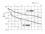
- FIG. 4 is a diagram showing the result of the filtration test of the mesh filter 1 according to this embodiment in comparison with the result of the filtration test of the mesh filter according to the comparative example.
- the mesh filter 1 according to this embodiment used in this filtration test has an inner cylinder 2 having an outer diameter of 10 mm, an outer cylinder 3 having an outer diameter of 16 mm, an inner cylinder 2 having a thickness of 1 mm, and an outer cylinder 3 having a thickness of 1. 1 mm, the rib width L2 of the vertical rib 6 and the rib width L3 of the horizontal rib 7 are 0.1 mm, the groove width L4 of the vertical groove 6a and the groove width L5 of the horizontal groove 7a are 0.1 mm, and one side of the regular rectangular opening 8 is The total thickness L6 of the filter part 4 is 0.35 mm, the thickness L7 of the vertical rib 6 is 0.2 mm, and the thickness L8 of the horizontal rib 7 is 0.15 mm. (See FIG. 2).
- the mesh filter 1 having such dimensions was attached to the test tube so that the test solution passed only through the filter unit 4. Further, in the mesh filter 1, the thickness L 7 of the vertical rib 6 is larger than the thickness L 8 of the horizontal rib 7, and the rigidity on the side of the vertical rib 6 is higher than the rigidity of the horizontal rib 7. Vertical ribs 6 were arranged on the side.
- the test solution used is a mixture of glass beads having a particle size of 0.105 to 0.125 ⁇ m mixed with water (solvent) to a concentration of 0.01 g / L (0.01 gram per liter). It was.
- this test solution is sucked from the test pipe line downstream of the mesh filter 1 by a pump so that the flow rate is 1.0 L / min (1.0 liter per minute), and the upstream side of the mesh filter 1
- Pressure loss Differential pressure in the test pipe before and after (upstream and downstream) of the mesh filter 1 with the first pressure gauge arranged in the test pipe and the second pressure gauge arranged in the test pipe downstream of the mesh filter 1 ( Pressure loss) was measured.
- Pressure loss Pressure loss
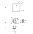
- FIG. 5 is a diagram showing a mesh filter 300 according to a comparative example.
- the mesh filter 300 according to this comparative example is formed by insert molding as in the first conventional example, and is radially inward of the mesh member 301 formed by knitting synthetic resin fibers (for example, nylon fibers).
- An inner cylinder 302 is formed on the side by injection molding
- an outer cylinder 303 is formed on the radially outer side of the mesh member 301 by injection molding
- a connecting rib 304 that connects the inner cylinder 302 and the outer cylinder 303 in the radial direction is formed.
- Three locations are formed at equal intervals along the circumferential direction of the front and back surfaces of the mesh member 301.
- the mesh filter 300 according to this comparative example is different from the filter unit 4 of the mesh filter 1 according to the present embodiment in that the mesh member 301 and the connecting rib 304 are different in mesh and shape according to the present embodiment. It is formed in the same shape and size as the filter 1.
- the outer diameter of the inner cylinder 302 is 10 mm
- the outer diameter of the outer cylinder 303 is 16 mm
- the thickness of the inner cylinder 302 is 1 mm
- the thickness of the outer cylinder 303 is 1 mm
- the length along the central axis 306 of the outer cylinder 303 is L1, and is the same as each part except the filter part 4 of the mesh filter 1 according to the present embodiment.
- the mesh filter 300 according to this comparative example is formed so that the mesh member 301 is knitted with a fiber 307 made of a synthetic resin material having a wire diameter of 0.06 mm, and one side of the substantially rectangular opening 308 of the mesh member 301.
- the aperture ratio of the mesh member 301 of the mesh filter 300 according to the comparative example (the ratio of the total area of the openings 308 of the mesh member 301 to the surface area of the mesh member 301 located between the inner cylinder 302 and the outer cylinder 303) is 39%
- the mesh filter 1 according to the present embodiment has an aperture ratio (ratio of the total area of the opening 8 to the surface area of the filter unit 4) of 25%
- the mesh filter 1 according to the present embodiment Is larger than the aperture ratio.
- the mesh filter 300 according to this comparative example exemplifies a mode in which a gate for injection molding at the time of insert molding is provided on the front-side connecting rib 304 (see the gate mark 305 in FIG. 5A), but injection molding. It can also be formed by providing a gate for the inner cylinder 302.
- the mesh filter 300 according to the comparative example is attached to the test pipe so that the test solution passes only through the mesh member 301, and the filtration test is performed in the same manner as the filtration test of the mesh filter 1 according to the present embodiment. .
- the measurement result is shown as the second test result in FIG.
- the pressure in the test pipe line decreases at a substantially constant rate with the passage of time, and abrupt clogging does not occur.
- the mesh filter 300 according to the comparative example causes a rapid pressure drop immediately after the start of the test, causes a sudden clogging, and then the pressure in the test pipe line decreases at a substantially constant rate with time.
- the ratio of the pressure drop is larger than that of the mesh filter 1 according to the present embodiment.
- the mesh filter 1 according to the present embodiment is easier to predict the cleaning time of the filter unit 4 or the filter replacement time than the mesh filter 300 according to the comparative example. From the test results shown in FIG. 4, it was found that the mesh filter 1 according to this embodiment is less likely to be clogged and can maintain the filtration function for a long period of time as compared with the mesh filter 300 according to the comparative example. .
- the mesh filter 1 according to the present embodiment has high rigidity of the filter portion 4, the shape of the opening portion 8 is not changed, and cleaning after the filtration test (removal of glass beads) is easy.
- the mesh filter 300 according to the comparative example has a weak mesh member 301 and is easily deformed. Therefore, the shape of the opening 308 changes, and the glass beads are bitten into the opening 308. Later cleaning was difficult.
- the mesh filter 300 according to the comparative example has a poor shape accuracy of the opening and the shape easily changes, there is a possibility that foreign matters to be filtered out may pass through.
- the mesh filter 1 according to the present embodiment as described above (inner cylinder 2, outer cylinder 3, and filter portion 4) is integrally and highly accurately injection molded, In comparison, the productivity is improved and the product price is reduced while maintaining the performance as a filter.
- the plurality of openings 8 of the filter unit 4 have the same shape in the mesh filter 1 according to the present embodiment, for example, by being arranged in a fuel supply line connected to a fuel injection device of an automobile, Foreign matter in the fuel having a size exceeding the maximum width of the opening can be reliably filtered out, and the fuel from which the foreign matter has been removed can be smoothly discharged from the opening 8.
- the mesh filter 200 according to the second conventional example which does not have the same opening area in the entire area of the filter portion 202, is the lower limit of the particle size of foreign matter that can be filtered out by the filter portion 202.
- the value may vary, and foreign matter to be passed through the filter unit 202 may be filtered out, or foreign matter that needs to be filtered out by the filter unit 202 may be allowed to pass, and the filter performance will be insufficient.
- the mesh filter 1 according to the present embodiment does not vary in the lower limit value of the particle size of the foreign matter that can be filtered out, and improves the filter performance as compared with the case where the opening area varies. Can be made.
- the number of openings 8 can be increased, and the opening area of the filter unit 4 can be increased.
- the mesh filter 1 according to the present embodiment is compared with the mesh filter 200 of the second conventional example in which the rib width (W1) of the vertical ribs 203 and the rib width (W2) of the horizontal ribs 204 are two times different from each other.
- the pressure loss in the part 4 can be reduced, and the filter performance can be improved.
- FIG. 6 is a diagram showing a mesh filter 1 according to the second embodiment of the present invention.
- the mesh filter 1 according to the present embodiment shown in FIG. 6 has the same reference numerals as those of the mesh filter 1 according to the first embodiment, and a description overlapping that of the mesh filter 1 according to the first embodiment. Omitted.
- a center side filter portion 24 extending from the central axis 5 of the inner cylinder 2 to the inner peripheral surface 2d of the inner cylinder 2 is formed on the radially inner side of the inner cylinder 2.
- This center side filter part 24 is formed similarly to the filter part 4 of the mesh filter 1 which concerns on the said 1st Embodiment (refer FIG. 2).
- the particle size of the foreign matter to be filtered out by the center-side filter portion 24 and the particle size of the foreign matter to be filtered out by the filter portion 4 are different, the particle size of the foreign matter to be filtered out.
- the opening area of the opening 8 of the center side filter part 24 and the opening 8 of the filter part 4 may be changed according to the above.
- FIG. 7 is a view showing a mold 10 used for injection molding of the mesh filter 1 according to this embodiment, and is a cross-sectional view corresponding to FIG.
- the same parts as those of the mold 10 of FIG. 3 are denoted by the same reference numerals, and description overlapping with the description of the mold 10 of FIG. 3 is omitted.
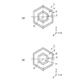
- FIG. 8 is a diagram (a diagram corresponding to FIGS. 1A and 6A) showing a mesh filter 1 according to the third embodiment of the present invention, and the mesh filter according to the first and second embodiments. It is a figure which shows the modification of 1.
- FIG. 8A is a diagram showing a modification of the mesh filter 1 according to the first embodiment
- FIG. 8B is a diagram showing a modification of the mesh filter 1 according to the second embodiment.
- the mesh filter 1 has a regular hexagonal shape on the front side of the inner cylinder 2 and the outer cylinder 3.
- the mesh filter 1 may have a shape corresponding to a mating member (a fuel pipe or the like) to which the shapes of the inner cylinder 2 and the outer cylinder 3 can be attached as long as fuel leakage can be prevented.
- the shape of the front side of the inner cylinder 2 and the outer cylinder 3 may be a polygon of a regular pentagon or more.
- the shape of the inner cylinder 2 and the outer cylinder 3 may be changed so that the shape of the front side of the inner cylinder 2 is a circle and the shape of the front side of the outer cylinder 3 is a regular octagon.
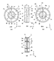
- FIG. 9A is a front view of the mesh filter 1
- FIG. 9B is a side view of the mesh filter 1
- FIG. 9C is a rear view of the mesh filter 1
- FIG. d) is a cross-sectional view of the mesh filter 1 cut along the line A5-A5 of FIG.
- FIG. 10A is an enlarged view of part B7 in FIG. 9A (partially enlarged view of the mesh filter 1)
- FIG. 10B is along the line A6-A6 in FIG. 10A
- FIG. 10C is a cross-sectional view (partially enlarged cross-sectional view of the mesh filter 1) shown in FIG. 10
- FIG. 10C is a cross-sectional view taken along the line A7-A7 of FIG. 10 (d) is an enlarged view of part B8 in FIG. 9 (c) (partially enlarged view of the mesh filter 1).
- the mesh filter 1 includes a disk-shaped gate connection portion 26, a cylinder that is concentric with the central axis 27 of the gate connection portion 26 and that surrounds the gate connection portion 26. And a filter portion 4 that integrally connects the outer peripheral surface 26a of the gate connection portion 26 and the inner peripheral surface 3a of the outer tube 3 along the radial direction.
- the entire mesh filter 1 is integrally formed of resin (POM (polyacetal, for example, M450-44), 66 nylon, etc.).
- POM polyacetal, for example, M450-44
- Such a mesh filter 1 is disposed, for example, in a fuel supply pipe connected to a fuel injection device of an automobile, and the outer cylinder 3 is attached to the fuel supply pipe or the like via a seal member (not shown).
- the fuel (fluid) passing through the filter unit 4 is used so as not to leak.
- the gate connection portion 26 is a portion where the injection molding gate 28 is opened, and the outer dimension is set to be larger than the inner diameter dimension of the opening of the gate 28.
- the gate connecting portion 26 is separated from the injection molding gate 28 before the injection molding is finished and the mesh filter 1 as a product is taken out from the mold 10.
- the wall thickness is set so as not to break.
- the surface 26 b of the gate connection portion 26 protrudes from the surface of the filter portion 4 by the same dimension as the thickness of the filter portion 4.
- the back surface 26 c of the gate connection portion 26 protrudes from the back surface of the filter portion 4 by the same dimension as the thickness of the filter portion 4.
- the outer cylinder 3 has a surface 3d that protrudes in a direction along the central axis 27 (+ Z-axis direction) from the surface 26b of the gate connection portion 26, and a back surface 3e that extends along the central axis 27 rather than the back surface 26c of the gate connection portion 26. Projecting in the direction (-Z-axis direction). And this outer cylinder 3 has accommodated the filter part 4 and the gate connection part 26 in the radial direction inner side.
- the shape of the outer cylinder 3 is appropriately changed according to the attachment portion structure of a mating member (such as a control oil supply pipe for the hydraulic control device) to which the mesh filter 1 is attached.
- the filter unit 4 is formed along the XY plane, where a virtual plane orthogonal to the direction along the central axis 27 of the gate connection unit 26 is an XY plane.
- a plurality of vertical ribs 6 that are orthogonal to the X axis and extend along the Y axis are formed at equal intervals in parallel to the Y axis on the front side of the filter unit 4.
- a plurality of lateral ribs 7 that are orthogonal to the longitudinal ribs 6 and extend along the X axis are formed at equal intervals in parallel with the X axis on the back surface side of the filter unit 4.
- parts other than the connection part with the gate connection part 26 and the connection part with the outer cylinder 3 in the filter part 4 are the horizontal ribs adjacent to the adjacent vertical ribs 6 and 6.
- a regular square opening 8 is formed between 7 and 7. That is, the opening 8 is formed at the intersection of the vertical groove 6a between the adjacent vertical ribs 6 and 6 and the horizontal groove 7a between the adjacent horizontal ribs 7 and 7, and the intersection of the vertical groove 6a and the horizontal groove 7a.
- the same number (plural) is formed.
- the mesh filter 1 has a symmetrical shape with respect to the center line 30 in the width direction of the outer cylinder 3, but the filter part 4 and the gate connection part 26 are arranged in the center line 30 in the width direction. May be shifted in the direction along the central axis 27 (+ Z-axis direction or -Z-axis direction). Further, in FIG. 9B, the mesh filter 1 has either one of the filter portion 4 and the gate connection portion 26 in a direction along the central axis 27 with respect to the center line 30 in the width direction of the outer cylinder 3 (+ Z-axis direction). Or in the ⁇ Z-axis direction). Moreover, the filter part 4 may form several vertical rib 6 in a back side, and may form several horizontal rib 7 in the front side.
- the outer diameter D1 of the outer cylinder 3 is 7.0 mm
- the width (length in the direction along the central axis 27) L1 of the outer cylinder 3 is 2 mm
- the inner diameter D2 of the outer cylinder 3 is 4 mm
- the gate The outer diameter D3 of the connecting portion 26 is 1.5 mm
- the width (length in the direction along the central axis 27) L9 of the gate connecting portion 26 is 0.9 mm.
- the mesh filter 1 has a rib width L2 of the vertical rib 6 and a rib width L3 of the horizontal rib 7 of 0.07 mm, a groove width L4 of the vertical groove 6a and a groove width L5 of the horizontal groove 7a of 0.077 mm, and a regular square opening.
- One side of the portion 8 is formed to 0.077 mm.
- the mesh filter 1 has a total thickness L6 of the filter portion 4 of 0.3 mm, a thickness of the vertical rib 6 (a dimension along the Z axis) L7 of 0.15 mm, and a thickness of the horizontal rib 7.
- the dimension (dimension in the direction along the Z axis) L8 is formed to be 0.15 mm.
- the gate inner diameter (the diameter of the gate mark 28a) is 0.8 mm.
- the numerical value shown in the Example of this mesh filter 1 is for facilitating understanding of the mesh filter 1 according to this embodiment as described above, and the mesh filter 1 according to this embodiment is limited. It is not to be changed, and is appropriately changed according to the use conditions and the like.
- FIG. 11 is a view showing a mold 10 used for injection molding of the mesh filter 1 according to the present embodiment.
- 11A is a longitudinal sectional view of the mold 10
- FIG. 11B is an enlarged view of a portion B10 in FIG. 11A (a partially enlarged sectional view of the mold 10).
- 11 (c) is a partial plan view of the first mold 11 viewed from the direction D3 in FIG. 11 (b), and
- FIG. 11 (d) is viewed from the direction D4 in FIG. 11 (b).
- 2 is a partial plan view of the second mold 12.
- FIG. 11 is a view showing a mold 10 used for injection molding of the mesh filter 1 according to the present embodiment.
- 11A is a longitudinal sectional view of the mold 10
- FIG. 11B is an enlarged view of a portion B10 in FIG. 11A (a partially enlarged sectional view of the mold 10).
- 11 (c) is a partial plan view of the first mold 11 viewed from the direction D3 in FIG. 11 (
- the mold 10 has a cavity 13 for injection molding the mesh filter 1 on the mold mating surface side of the first mold 11 and the second mold 12.
- the cavity 13 includes a disk-shaped first cavity portion 14 for forming the gate connection portion 26 of the mesh filter 1, a cylindrical second cavity portion 15 for forming the outer cylinder 3 of the mesh filter 1, and the mesh filter And a hollow disc-shaped third cavity portion 16 for forming one filter portion 4.
- the first mold 11 is provided with one gate 28 at the center of the first cavity portion 14 that opens toward the one end face 14a in the direction along the central axis 31 of the first cavity portion 14 (FIG. 9). (See gate mark 28a in (c)).
- the portion forming the third cavity portion 16 of the first mold 11 is formed with a plurality of lateral rib grooves 20 (the same number as the lateral ribs 7) for forming the lateral rib 7 (the same number as the lateral rib 7) (FIG. 11B). ) To (c)).
- the lateral rib groove 20 has a rectangular cross-sectional shape and is formed to have a constant groove width along the X-axis direction. And between the adjacent horizontal rib grooves 20 and 20, the protrusion 21 between horizontal rib grooves for forming the horizontal groove 7a is formed.
- the lateral rib groove protrusion 21 has a rectangular cross-sectional shape and is formed to have a constant protrusion width L4 along the X-axis direction (see FIGS. 11B to 11C). . Further, in the portion forming the third cavity portion 16 of the second mold 12, a plurality of the vertical rib grooves 22 for forming the vertical ribs 6 (the same number as the vertical ribs 6) are formed at equal intervals (FIG. 11B). ), (D)). The vertical rib groove 22 has a rectangular cross-sectional shape and is formed to have a constant groove width (the same groove width as that of the lateral rib groove 20) along the Y-axis direction.
- the mold 10 When the first mold 11 and the second mold 12 are clamped, the mold 10 has the projections 21 between the lateral rib grooves of the first mold 11 and the projections 23 between the vertical rib grooves of the second mold 12. Since the resin is abutted so as to cross in a cross shape, even if molten resin is injected into the cavity 13, the protrusions 21 between the lateral rib grooves of the first mold 11 and the vertical rib grooves of the second mold 12. The melted resin is not filled in the intersecting portion where the protrusions 23 overlap, and the intersecting portion where the protrusions 21 between the lateral rib grooves of the first mold 11 and the protrusions 23 between the vertical rib grooves of the second mold 12 overlap is a square opening. It becomes 8.
- the gate 28 opened to the cavity 13 is illustrated as being installed at only one location in the center of the first cavity portion 14.
- the present invention is not limited to this, and the outer diameter of the first cavity portion 14, etc. Depending on the situation, it may be provided at two or more places.
- the resin in the molten state is fed from the gate 28 into the cavity 13. Then, the pressure in the cavity 13 is maintained at a predetermined pressure, and the mold 10 is cooled. Thereafter, the gate 28 is separated from the injection molded product (mesh filter) in the cavity 13, the second mold 12 is separated from the first mold 11 in the ⁇ C direction (the mold is opened), and the mesh filter in the cavity 13. 1 is pushed out from the cavity 13 by an ejector pin (not shown), and the mesh filter 1 which is an injection-molded product is taken out from the mold 10 (see FIGS. 9 and 10).
- the second mold 12 in the mold open state is moved in the + C direction (direction approaching the first mold 11), and the second mold 12 is pressed against the first mold 11. Then, the first mold 11 and the second mold 12 are clamped.
- One cycle of injection molding of the mesh filter 1 according to this embodiment is shorter than one cycle of insert molding of the mesh filter 100 according to the first conventional example.
- the mesh filter 1 according to the present embodiment is more productive than the mesh filter 100 according to the first conventional example, and the product price is lower than that of the mesh filter 100 according to the first conventional example.
- the mesh filter 1 according to the present embodiment as described above is obtained by replacing the cylindrical inner cylinder 2 of the mesh filter 1 according to the first embodiment with a disk-shaped gate connection portion 28.
- the dimensions of the filter unit 4 are different from those of the mesh filter 1 of the first embodiment, the basic structure is the same as that of the mesh filter 1 according to the first embodiment. Therefore, the mesh filter 1 according to the present embodiment can obtain the same effects as the mesh filter 1 according to the first embodiment.
- the mesh filter 1 according to the present invention has been illustrated as being installed in a fuel supply pipe connected to a fuel injection device of an automobile.
- the mesh filter 1 is installed in the middle of an oil pipeline such as an automobile lubrication device.
- the present invention is not limited to this, and can be used in a wide range of technical fields in order to remove foreign matters mixed with fluid (liquid such as water or gas such as air) by installing it in the pipelines of water supply pipes or air blow pipes. .
- the mesh filter 1 according to the first to fourth embodiments is not limited to the thermoplastic resin injection-molded product, and may be a thermosetting resin injection-molded product, and the material is appropriately selected according to the intended use. Is done.
- the mesh filter 1 according to the first to fourth embodiments has exemplified the configuration in which the vertical rib 6 and the horizontal rib 7 are orthogonal to each other, the present invention is not limited to this, and the vertical rib 6 and the horizontal rib 7 intersect diagonally. It may be configured.
- the shape of the front side of the gate connection portion 26 is circular.
- the shape is not limited to this, and the shape of the front side of the gate connection portion 26 is polygonal (six The shape on the front side of the gate connection portion 26 is determined in consideration of the flow of the molten resin at the time of injection molding.
- SYMBOLS 1 Mesh filter, 2 ... Inner cylinder (gate connection part), 2a, 26a ... Outer surface, 3 ... Outer cylinder, 3a ... Inner surface, 4 ... Filter part, 5, 27 ... Center axis , 6... Vertical rib, 6a... Vertical groove, 7 .. side rib, 7a .. lateral groove, 8... Opening, 10. Part), 18 ... pin gate (gate), 26 ... gate connection, 28 ... gate, L2, L3 ... rib width
Landscapes
- Chemical & Material Sciences (AREA)
- Chemical Kinetics & Catalysis (AREA)
- Engineering & Computer Science (AREA)
- Manufacturing & Machinery (AREA)
- Mechanical Engineering (AREA)
- Moulds For Moulding Plastics Or The Like (AREA)
- Filtering Materials (AREA)
- Filtration Of Liquid (AREA)
- Lubrication Details And Ventilation Of Internal Combustion Engines (AREA)
- General Details Of Gearings (AREA)
Abstract
Description
図12は、第1従来例のメッシュフィルタ100を示す図である。なお、図12(a)は第1従来例のメッシュフィルタ100の平面図であり、図12(b)は図12(a)のA10-A10線に沿って切断して示すメッシュフィルタ100の断面図である。また、図12(c)は第1従来例のメッシュフィルタ100の成形方法における第1段階を説明するための金型101の断面図であり、図12(d)は第1従来例のメッシュフィルタ100の成形方法における第2段階を説明するための金型101の断面図であり、図12(e)は図12(a)のB11部の拡大図である。
図13は、第2従来例に係るメッシュフィルタ200を示す図であり、射出成形されたメッシュフィルタ200を示す図である。この図13に示したメッシュフィルタ200は、枠体部201とフィルタ部202とが射出成形により一体として形成されるため、第1従来例のメッシュフィルタ100のような問題を生じない(特許文献3,4参照)。
図1乃至図2は、本発明の第1実施形態に係るメッシュフィルタ1を示す図である。なお、図1(a)はメッシュフィルタ1の正面図であり、図1(b)はメッシュフィルタ1の側面図であり、図1(c)はメッシュフィルタ1の背面図であり、図1(d)は図1(a)のA1-A1線に沿って切断して示すメッシュフィルタ1の断面図である。また、図2(a)は図1(a)のB1部の拡大図(メッシュフィルタ1の一部拡大図)であり、図2(b)は図2(a)のA2-A2線に沿って切断して示す断面図(メッシュフィルタ1の一部拡大断面図)であり、図2(c)は図2(a)のA3-A3線に沿って切断して示す断面図(メッシュフィルタ1の一部拡大断面図)であり、図2(d)は図1(c)のB2部の拡大図(メッシュフィルタ1の一部拡大図)である。
次に、本実施形態に係るメッシュフィルタ1の理解を容易にするため、メッシュフィルタ1の実施例を説明する。例えば、メッシュフィルタ1は、内筒2の外径が10mm、外筒3の外径が16mm、内筒2の肉厚が1mm、及び外筒3の肉厚が1mmに形成される。また、メッシュフィルタ1は、縦リブ6のリブ幅L2及び横リブ7のリブ幅L3が0.1mm、縦溝6aの溝幅L4及び横溝7aの溝幅L5が0.1mm、正四角形の開口部8の一辺が0.1mmに形成される。また、メッシュフィルタ1は、フィルタ部4の総肉厚寸法L6が0.35~0.8mm、縦リブ6の肉厚寸法(Z軸に沿った方向の寸法)L7の最大値が0.4mm、横リブ7の肉厚寸法(Z軸に沿った方向の寸法)L8の最大値が0.4mmの範囲で形成される。なお、フィルタ部4の総肉厚寸法L6が0.35mmの場合、縦リブ6の肉厚寸法L7が0.2mmで、横リブ7の肉厚寸法L8が0.15mmに形成される。なお、このメッシュフィルタ1の実施例に示した数値は、上述のように、本実施形態に係るメッシュフィルタ1の理解を容易にするためのものであり、本実施形態に係るメッシュフィルタ1を限定するものではなく、使用条件等に応じて適宜変更される。
図6は、本発明の第2実施形態に係るメッシュフィルタ1を示す図である。この図6に示す本実施形態に係るメッシュフィルタ1は、第1実施形態に係るメッシュフィルタ1と同一部分に同一符号を付し、第1実施形態に係るメッシュフィルタ1の説明と重複する説明を省略する。
図8は、本発明の第3実施形態に係るメッシュフィルタ1を示す図(図1(a),図6(a)に対応する図)であり、第1及び第2実施形態に係るメッシュフィルタ1の変形例を示す図である。なお、図8(a)が第1実施形態に係るメッシュフィルタ1の変形例を示す図であり、図8(b)が第2実施形態に係るメッシュフィルタ1の変形例を示す図である。
図9乃至図10は、本発明の第4実施形態に係るメッシュフィルタ1を示す図である。なお、図9(a)はメッシュフィルタ1の正面図であり、図9(b)はメッシュフィルタ1の側面図であり、図9(c)はメッシュフィルタ1の背面図であり、図9(d)は図9(a)のA5-A5線に沿って切断して示すメッシュフィルタ1の断面図である。また、図10(a)は図9(a)のB7部の拡大図(メッシュフィルタ1の一部拡大図)であり、図10(b)は図10(a)のA6-A6線に沿って切断して示す断面図(メッシュフィルタ1の一部拡大断面図)であり、図10(c)は図10(a)のA7-A7線に沿って切断して示す断面図(メッシュフィルタ1の一部拡大断面図)であり、図10(d)は図9(c)のB8部の拡大図(メッシュフィルタ1の一部拡大図)である。
次に、本実施形態に係るメッシュフィルタ1の理解を容易にするため、メッシュフィルタ1の実施例を説明する。例えば、メッシュフィルタ1は、外筒3の外径D1が7.0mm、外筒3の幅(中心軸27に沿った方向の長さ)L1が2mm、外筒3の内径D2が4mm、ゲート接続部26の外径D3が1.5mm、ゲート接続部26の幅(中心軸27に沿った方向の長さ)L9が0.9mmに形成される。また、メッシュフィルタ1は、縦リブ6のリブ幅L2及び横リブ7のリブ幅L3が0.07mm、縦溝6aの溝幅L4及び横溝7aの溝幅L5が0.077mm、正四角形の開口部8の一辺が0.077mmに形成される。また、メッシュフィルタ1は、フィルタ部4の総肉厚寸法L6が0.3mm、縦リブ6の肉厚寸法(Z軸に沿った方向の寸法)L7が0.15mm、横リブ7の肉厚寸法(Z軸に沿った方向の寸法)L8が0.15mmに形成される。また、ゲート内径(ゲート痕28aの直径)は、0.8mmである。なお、このメッシュフィルタ1の実施例に示した数値は、上述のように、本実施形態に係るメッシュフィルタ1の理解を容易にするためのものであり、本実施形態に係るメッシュフィルタ1を限定するものではなく、使用条件等に応じて適宜変更される。
なお、本発明に係るメッシュフィルタ1は、自動車の燃料噴射装置に接続される燃料供給管に設置される態様を例示したが、もちろん、自動車の潤滑装置等のオイル管路の途中に設置してもよく、これに限られず、給水管や送風管の管路に設置し、流体(水等の液体や空気等の気体)に混ざった異物を取り除くために広範囲の技術分野で使用することができる。
Claims (3)
- 流体中の異物を濾し取るために使用されるメッシュフィルタにおいて、
射出成形用のゲートが配置されるゲート接続部と、
前記ゲート接続部を取り囲む外筒と、
前記ゲート接続部の外周面と前記外筒の内周面とを前記ゲート接続部の径方向に沿って接続するフィルタ部と、
を有し、
前記フィルタ部は、前記ゲート接続部の中心軸に直交する仮想平面をX-Y平面とすると、このX-Y平面に沿って形成されており、
前記フィルタ部のうちの前記ゲート接続部との接続部分及び前記外筒との接続部分以外の部分は、前記X-Y平面に沿って平行に且つ等間隔に複数形成された縦リブと、前記X-Y平面に沿って平行に且つ等間隔に複数形成されて前記縦リブと交差する横リブと、これら複数の縦リブと複数の横リブとの間に複数形成された開口部と、を有し、
前記縦リブは、前記フィルタ部の表側と裏側のいずれか一方側に配置され、
前記横リブは、前記フィルタ部の表側と裏側のいずれか他方側に配置され、
前記開口部は、隣り合う前記縦リブ間の縦溝と隣り合う前記横リブ間の横溝との交差部に形成され、
金型のキャビティのうちの前記ゲート接続部を形作るキャビティ部分に開口するゲートから前記キャビティ部分に溶融状態の樹脂が射出されることにより、前記ゲート接続部、前記外筒、及び前記フィルタ部が一体に形成されると共に、前記縦リブ及び前記横リブのリブ幅が一定寸法に形成され、且つ、前記開口部が同一の形状に複数形成された、
ことを特徴とするメッシュフィルタ。 - 流体中の異物を濾し取るために使用されるメッシュフィルタにおいて、
内筒と、
前記内筒を取り囲む外筒と、
前記内筒の外周面と前記外筒の内周面とを前記内筒の径方向に沿って接続するフィルタ部と、
を有し、
前記フィルタ部は、前記内筒の中心軸に直交する仮想平面をX-Y平面とすると、このX-Y平面に沿って形成されており、
前記フィルタ部のうちの前記内筒との接続部分及び前記外筒との接続部分以外の部分は、X軸に直交し且つY軸と並行に等間隔で複数形成された縦リブと、この縦リブと直交し且つ前記X軸と並行に等間隔で複数形成された横リブと、これら複数の縦リブと複数の横リブとの間に複数形成された四角形状の開口部と、を有し、
前記縦リブは、前記フィルタ部の表側と裏側のいずれか一方側に配置され、
前記横リブは、前記フィルタ部の表側と裏側のいずれか他方側に配置され、
前記開口部は、隣り合う前記縦リブ間の縦溝と隣り合う前記横リブ間の横溝との交差部に形成され、
金型のキャビティのうちの前記内筒を形作るキャビティ部分に開口するゲートから前記キャビティ部分に溶融状態の熱可塑性樹脂が射出されることにより、前記内筒、前記外筒、及び前記フィルタ部が一体に形成されると共に、前記縦リブ及び前記横リブのリブ幅が一定寸法に形成され、且つ、前記開口部が同一の形状に複数形成された、
ことを特徴とするメッシュフィルタ。 - 前記内筒の中心軸から前記内筒の内周面に至る中心側フィルタ部を有し、
前記中心側フィルタ部は、前記内筒の中心軸に直交する仮想平面をX-Y平面とすると、このX-Y平面に沿って形成されており、
前記中心側フィルタ部のうちの前記内筒との接続部分以外の部分は、X軸に直交し且つY軸と並行に等間隔で複数形成された縦リブと、この縦リブと直交し且つ前記X軸と並行に等間隔で複数形成された横リブと、これら複数の縦リブと複数の横リブとの間に複数形成された四角形状の開口部と、を有し、
前記縦リブは、前記フィルタ部の表側と裏側のいずれか一方側に配置され、
前記横リブは、前記フィルタ部の表側と裏側のいずれか他方側に配置され、
前記開口部は、隣り合う前記縦リブ間の縦溝と隣り合う前記横リブ間の横溝との交差部に形成され、
金型のキャビティのうちの前記内筒を形作るキャビティ部分に開口するゲートから前記キャビティ部分に溶融状態の熱可塑性樹脂が射出されることにより、前記内筒、前記外筒、前記フィルタ部及び前記中心側フィルタ部が一体に形成されると共に、前記縦リブ及び前記横リブのリブ幅が一定寸法に形成され、且つ、前記開口部が同一の形状に複数形成された、
ことを特徴とする請求項2に記載のメッシュフィルタ。
Priority Applications (3)
| Application Number | Priority Date | Filing Date | Title |
|---|---|---|---|
| EP14869278.3A EP3081362B1 (en) | 2013-12-13 | 2014-12-03 | Mesh filter |
| US15/100,813 US20160303495A1 (en) | 2013-12-13 | 2014-12-03 | Mesh filter |
| CN201480061922.1A CN105722657A (zh) | 2013-12-13 | 2014-12-03 | 网格过滤器 |
Applications Claiming Priority (6)
| Application Number | Priority Date | Filing Date | Title |
|---|---|---|---|
| JP2013257959 | 2013-12-13 | ||
| JP2013-257959 | 2013-12-13 | ||
| JP2014007789 | 2014-01-20 | ||
| JP2014-007789 | 2014-01-20 | ||
| JP2014-043488 | 2014-03-06 | ||
| JP2014043488A JP6305116B2 (ja) | 2013-12-13 | 2014-03-06 | メッシュフィルタ |
Publications (1)
| Publication Number | Publication Date |
|---|---|
| WO2015087746A1 true WO2015087746A1 (ja) | 2015-06-18 |
Family
ID=53371055
Family Applications (1)
| Application Number | Title | Priority Date | Filing Date |
|---|---|---|---|
| PCT/JP2014/081928 WO2015087746A1 (ja) | 2013-12-13 | 2014-12-03 | メッシュフィルタ |
Country Status (5)
| Country | Link |
|---|---|
| US (1) | US20160303495A1 (ja) |
| EP (1) | EP3081362B1 (ja) |
| JP (1) | JP6305116B2 (ja) |
| CN (1) | CN105722657A (ja) |
| WO (1) | WO2015087746A1 (ja) |
Families Citing this family (8)
| Publication number | Priority date | Publication date | Assignee | Title |
|---|---|---|---|---|
| JP6453667B2 (ja) * | 2015-02-23 | 2019-01-16 | 株式会社エンプラス | メッシュフィルタの射出成形金型及びメッシュフィルタの射出成形方法 |
| JP6594703B2 (ja) * | 2015-08-26 | 2019-10-23 | 株式会社エンプラス | メッシュフィルタの射出成形方法、射出成形金型、及びメッシュフィルタ |
| JP6778013B2 (ja) * | 2016-05-11 | 2020-10-28 | 株式会社エンプラス | メッシュフィルタ |
| DE102016012936A1 (de) * | 2016-10-27 | 2018-05-03 | Mann + Hummel Gmbh | Flüssigkeitsreinigungselement, Flüssigkeitsreinigungssystem und Verfahren zur Herstellung eines Flüssigkeitsreinigungselements |
| JP2018127893A (ja) * | 2017-02-06 | 2018-08-16 | アイシン精機株式会社 | オイルセパレータおよびオイルセパレータの製造方法 |
| WO2020116302A1 (ja) * | 2018-12-03 | 2020-06-11 | 株式会社エンプラス | メッシュフィルタ |
| JP2020089802A (ja) * | 2018-12-03 | 2020-06-11 | 株式会社エンプラス | フィルタ付きカートリッジ |
| JP7317751B2 (ja) * | 2020-03-11 | 2023-07-31 | 愛三工業株式会社 | キャニスタ |
Citations (12)
| Publication number | Priority date | Publication date | Assignee | Title |
|---|---|---|---|---|
| JPS6485363A (en) * | 1987-09-26 | 1989-03-30 | Hisaka Works Ltd | Treatment of fishing net |
| JPH0379320A (ja) * | 1989-08-22 | 1991-04-04 | Taisei Sangyo Kk | フィルターの製造方法及びフィルター製造用金型 |
| JPH0544204U (ja) | 1991-11-26 | 1993-06-15 | 株式会社ニフコ | フイルタ取り付け構造 |
| JPH05293858A (ja) * | 1992-04-22 | 1993-11-09 | Mikio Aoki | 平面型フィルタの製造方法 |
| JPH06126784A (ja) * | 1992-10-21 | 1994-05-10 | Daisan Kanagata Seisakusho:Yugen | 格子状成型体の製造装置及び製法 |
| JPH07100317A (ja) | 1993-10-04 | 1995-04-18 | Daisan Kanagata Seisakusho:Kk | プラスチックフィルター及びその金型 |
| JPH07156156A (ja) | 1993-12-06 | 1995-06-20 | Daisan Kanagata Seisakusho:Kk | プラスチックフィルターとその金型 |
| JPH07284617A (ja) * | 1994-04-16 | 1995-10-31 | Daizo Kotaki | プラスチックフィルター及びプラスチック材料の供給路構造 |
| JPH07323438A (ja) * | 1994-05-31 | 1995-12-12 | Nissei Plastics Ind Co | 網目状製品の射出成形方法及び金型 |
| JPH10278075A (ja) * | 1997-04-07 | 1998-10-20 | Daisan Kanagata Seisakusho:Kk | 射出成形金型とその成形品 |
| JP2007001232A (ja) | 2005-06-27 | 2007-01-11 | Piolax Inc | メッシュフィルタの製造方法及びメッシュフィルタ製造用射出成形金型 |
| JP2013233732A (ja) * | 2012-05-09 | 2013-11-21 | Ono Sangyo Kk | フィルタ成形用金型装置および成形機と、樹脂フィルタの製造方法 |
Family Cites Families (12)
| Publication number | Priority date | Publication date | Assignee | Title |
|---|---|---|---|---|
| JPS6031319U (ja) * | 1983-08-05 | 1985-03-02 | 五葉工業株式会社 | プラスチツク製フイルタエレメント |
| US5650181A (en) * | 1993-06-17 | 1997-07-22 | Kotaki; Daizo | Injection molding die for producing plastic filter |
| JPH07137166A (ja) * | 1993-11-16 | 1995-05-30 | Daisan Kanagata Seisakusho:Kk | プラスチックフィルターとその金型 |
| JPH07300889A (ja) * | 1994-03-07 | 1995-11-14 | Daizo Kotaki | 排水口用プラスチックフィルター |
| JP2912853B2 (ja) * | 1995-06-20 | 1999-06-28 | 日精樹脂工業株式会社 | 合成樹脂による網状製品の成形方法及び成形金型 |
| DE19744361A1 (de) * | 1997-09-24 | 1999-03-25 | Theo Hillers | Kunststoff-Filter, insbesondere Kraftstoff-Filter |
| DE60323863D1 (de) * | 2002-11-22 | 2008-11-13 | Omnova Solutions Inc | Verfahren zur modifizierung und verwendung bestehender spritzgiessmaschinen um sie als in-mould beschichtungsvorrichtung zu verwenden |
| DE102004002963A1 (de) * | 2003-06-27 | 2005-01-13 | Friedrich Sanner Gmbh & Co Kg Spritzgusswerk | Sieb-oder Gitterstruktur in Bauteilen aus thermoplastischem Kunststoff, insbesondere als Abschluß von in Behältern bzw. Behälterverschlüssen gebildeten Kammern zur Aufnahme von rieselfähigen Trockenstoffmaterialien... |
| DE102006012214A1 (de) * | 2006-03-16 | 2007-09-20 | Siemens Ag | Kraftstofffilter und Verfahren zur Herstellung eines Kraftstofffilters |
| KR20080037245A (ko) * | 2006-10-25 | 2008-04-30 | 삼성전자주식회사 | 사출성형용 금형 및 이를 이용한 성형방법 |
| JP5368914B2 (ja) * | 2009-09-03 | 2013-12-18 | ダイキョーニシカワ株式会社 | オイルストレーナの製造方法 |
| JP6254794B2 (ja) * | 2013-08-20 | 2017-12-27 | 株式会社エンプラス | メッシュフィルタ |
-
2014
- 2014-03-06 JP JP2014043488A patent/JP6305116B2/ja active Active
- 2014-12-03 WO PCT/JP2014/081928 patent/WO2015087746A1/ja active Application Filing
- 2014-12-03 EP EP14869278.3A patent/EP3081362B1/en active Active
- 2014-12-03 US US15/100,813 patent/US20160303495A1/en not_active Abandoned
- 2014-12-03 CN CN201480061922.1A patent/CN105722657A/zh active Pending
Patent Citations (12)
| Publication number | Priority date | Publication date | Assignee | Title |
|---|---|---|---|---|
| JPS6485363A (en) * | 1987-09-26 | 1989-03-30 | Hisaka Works Ltd | Treatment of fishing net |
| JPH0379320A (ja) * | 1989-08-22 | 1991-04-04 | Taisei Sangyo Kk | フィルターの製造方法及びフィルター製造用金型 |
| JPH0544204U (ja) | 1991-11-26 | 1993-06-15 | 株式会社ニフコ | フイルタ取り付け構造 |
| JPH05293858A (ja) * | 1992-04-22 | 1993-11-09 | Mikio Aoki | 平面型フィルタの製造方法 |
| JPH06126784A (ja) * | 1992-10-21 | 1994-05-10 | Daisan Kanagata Seisakusho:Yugen | 格子状成型体の製造装置及び製法 |
| JPH07100317A (ja) | 1993-10-04 | 1995-04-18 | Daisan Kanagata Seisakusho:Kk | プラスチックフィルター及びその金型 |
| JPH07156156A (ja) | 1993-12-06 | 1995-06-20 | Daisan Kanagata Seisakusho:Kk | プラスチックフィルターとその金型 |
| JPH07284617A (ja) * | 1994-04-16 | 1995-10-31 | Daizo Kotaki | プラスチックフィルター及びプラスチック材料の供給路構造 |
| JPH07323438A (ja) * | 1994-05-31 | 1995-12-12 | Nissei Plastics Ind Co | 網目状製品の射出成形方法及び金型 |
| JPH10278075A (ja) * | 1997-04-07 | 1998-10-20 | Daisan Kanagata Seisakusho:Kk | 射出成形金型とその成形品 |
| JP2007001232A (ja) | 2005-06-27 | 2007-01-11 | Piolax Inc | メッシュフィルタの製造方法及びメッシュフィルタ製造用射出成形金型 |
| JP2013233732A (ja) * | 2012-05-09 | 2013-11-21 | Ono Sangyo Kk | フィルタ成形用金型装置および成形機と、樹脂フィルタの製造方法 |
Also Published As
| Publication number | Publication date |
|---|---|
| EP3081362B1 (en) | 2020-09-09 |
| US20160303495A1 (en) | 2016-10-20 |
| JP6305116B2 (ja) | 2018-04-04 |
| EP3081362A1 (en) | 2016-10-19 |
| EP3081362A4 (en) | 2017-08-09 |
| JP2015155187A (ja) | 2015-08-27 |
| CN105722657A (zh) | 2016-06-29 |
Similar Documents
| Publication | Publication Date | Title |
|---|---|---|
| JP6305116B2 (ja) | メッシュフィルタ | |
| JP6254794B2 (ja) | メッシュフィルタ | |
| WO2016158817A1 (ja) | メッシュフィルタ | |
| JP6366302B2 (ja) | メッシュフィルタ | |
| CN109070398A (zh) | 筛网过滤器 | |
| WO2016047205A1 (ja) | 筒状メッシュフィルタ | |
| JP6594703B2 (ja) | メッシュフィルタの射出成形方法、射出成形金型、及びメッシュフィルタ | |
| JP6453667B2 (ja) | メッシュフィルタの射出成形金型及びメッシュフィルタの射出成形方法 | |
| JP6522407B2 (ja) | メッシュフィルタ及びその製造方法 | |
| WO2016152596A1 (ja) | 網状成形品用射出成形金型、網状成形品用射出成形金型の製造方法、及び網状成形品 |
Legal Events
| Date | Code | Title | Description |
|---|---|---|---|
| 121 | Ep: the epo has been informed by wipo that ep was designated in this application |
Ref document number: 14869278 Country of ref document: EP Kind code of ref document: A1 |
|
| WWE | Wipo information: entry into national phase |
Ref document number: 15100813 Country of ref document: US |
|
| REEP | Request for entry into the european phase |
Ref document number: 2014869278 Country of ref document: EP |
|
| WWE | Wipo information: entry into national phase |
Ref document number: 2014869278 Country of ref document: EP |
|
| WWE | Wipo information: entry into national phase |
Ref document number: IDP00201603895 Country of ref document: ID |
|
| NENP | Non-entry into the national phase |
Ref country code: DE |