WO2015087447A1 - 補正係数算出部、画像変換部、色補正装置、表示装置、補正係数算出方法、及びプログラム - Google Patents
補正係数算出部、画像変換部、色補正装置、表示装置、補正係数算出方法、及びプログラム Download PDFInfo
- Publication number
- WO2015087447A1 WO2015087447A1 PCT/JP2013/083493 JP2013083493W WO2015087447A1 WO 2015087447 A1 WO2015087447 A1 WO 2015087447A1 JP 2013083493 W JP2013083493 W JP 2013083493W WO 2015087447 A1 WO2015087447 A1 WO 2015087447A1
- Authority
- WO
- WIPO (PCT)
- Prior art keywords
- image
- color
- unit
- correction
- display
- Prior art date
- Legal status (The legal status is an assumption and is not a legal conclusion. Google has not performed a legal analysis and makes no representation as to the accuracy of the status listed.)
- Ceased
Links
Images





Classifications
-
- H—ELECTRICITY
- H04—ELECTRIC COMMUNICATION TECHNIQUE
- H04N—PICTORIAL COMMUNICATION, e.g. TELEVISION
- H04N1/00—Scanning, transmission or reproduction of documents or the like, e.g. facsimile transmission; Details thereof
- H04N1/46—Colour picture communication systems
- H04N1/56—Processing of colour picture signals
- H04N1/60—Colour correction or control
- H04N1/603—Colour correction or control controlled by characteristics of the picture signal generator or the picture reproducer
- H04N1/6052—Matching two or more picture signal generators or two or more picture reproducers
- H04N1/6055—Matching two or more picture signal generators or two or more picture reproducers using test pattern analysis
-
- H—ELECTRICITY
- H04—ELECTRIC COMMUNICATION TECHNIQUE
- H04N—PICTORIAL COMMUNICATION, e.g. TELEVISION
- H04N1/00—Scanning, transmission or reproduction of documents or the like, e.g. facsimile transmission; Details thereof
- H04N1/46—Colour picture communication systems
-
- H—ELECTRICITY
- H04—ELECTRIC COMMUNICATION TECHNIQUE
- H04N—PICTORIAL COMMUNICATION, e.g. TELEVISION
- H04N1/00—Scanning, transmission or reproduction of documents or the like, e.g. facsimile transmission; Details thereof
- H04N1/46—Colour picture communication systems
- H04N1/56—Processing of colour picture signals
- H04N1/60—Colour correction or control
-
- H—ELECTRICITY
- H04—ELECTRIC COMMUNICATION TECHNIQUE
- H04N—PICTORIAL COMMUNICATION, e.g. TELEVISION
- H04N1/00—Scanning, transmission or reproduction of documents or the like, e.g. facsimile transmission; Details thereof
- H04N1/46—Colour picture communication systems
- H04N1/56—Processing of colour picture signals
- H04N1/60—Colour correction or control
- H04N1/6002—Corrections within particular colour systems
- H04N1/6008—Corrections within particular colour systems with primary colour signals, e.g. RGB or CMY(K)
-
- H—ELECTRICITY
- H04—ELECTRIC COMMUNICATION TECHNIQUE
- H04N—PICTORIAL COMMUNICATION, e.g. TELEVISION
- H04N1/00—Scanning, transmission or reproduction of documents or the like, e.g. facsimile transmission; Details thereof
- H04N1/46—Colour picture communication systems
- H04N1/56—Processing of colour picture signals
- H04N1/60—Colour correction or control
- H04N1/6011—Colour correction or control with simulation on a subsidiary picture reproducer
-
- H—ELECTRICITY
- H04—ELECTRIC COMMUNICATION TECHNIQUE
- H04N—PICTORIAL COMMUNICATION, e.g. TELEVISION
- H04N1/00—Scanning, transmission or reproduction of documents or the like, e.g. facsimile transmission; Details thereof
- H04N1/46—Colour picture communication systems
- H04N1/56—Processing of colour picture signals
- H04N1/60—Colour correction or control
- H04N1/603—Colour correction or control controlled by characteristics of the picture signal generator or the picture reproducer
- H04N1/6033—Colour correction or control controlled by characteristics of the picture signal generator or the picture reproducer using test pattern analysis
-
- H—ELECTRICITY
- H04—ELECTRIC COMMUNICATION TECHNIQUE
- H04N—PICTORIAL COMMUNICATION, e.g. TELEVISION
- H04N1/00—Scanning, transmission or reproduction of documents or the like, e.g. facsimile transmission; Details thereof
- H04N1/46—Colour picture communication systems
- H04N1/64—Systems for the transmission or the storage of the colour picture signal; Details therefor, e.g. coding or decoding means therefor
- H04N1/644—Systems for the transmission or the storage of the colour picture signal; Details therefor, e.g. coding or decoding means therefor using a reduced set of representative colours, e.g. each representing a particular range in a colour space
Definitions
- the present invention relates to a correction coefficient calculation unit, an image conversion unit, a color correction device, a display device, a correction coefficient calculation method, and a program.
- a personal computer used in a plurality of workflows and a display device connected to each PC may be used.
- the present invention has been made in view of the above problems, and a color correction device, a display device, a color correction method, and a color correction device that can easily adjust a plurality of display devices to an output of a reference printing device, and The purpose is to provide a program.
- a correction coefficient calculation unit shows a reference image output unit that generates a reference image, image information indicating color characteristics related to an image displayed on the display unit, and color characteristics related to a printing apparatus.
- a profile receiving unit that receives print information; a reference image decomposing unit that generates print characteristic data in which the reference image, the print information and the reference image color-converted based on the image information are associated with each other; .
- an image conversion unit obtains display correction data based on display information indicating color characteristics related to a display unit and image information indicating color characteristics related to an image displayed on the display unit.
- Print characteristic data created by associating a display correction data creation unit to be created, a reference image, print information indicating color characteristics relating to a printing apparatus, and the reference image color-converted based on the image information.
- a color correction apparatus is a color correction apparatus that includes a correction coefficient calculation unit and an image conversion unit, and the correction coefficient calculation unit generates a reference image.
- a profile receiving unit that receives image information indicating color characteristics related to an image displayed on the display unit, and print information indicating color characteristics related to a printing apparatus, the reference image, the print information, and the image information
- a reference image decomposition unit that creates print characteristic data in association with the color-converted reference image, and the image conversion unit includes display information indicating color characteristics related to the display unit, and
- a display correction data creating unit for creating display correction data based on image information indicating color characteristics relating to an image to be displayed; a reference image; and color characteristics relating to the printing apparatus.
- a print characteristic storage unit that receives print characteristic data created by associating the print information and the reference image color-converted based on the image information, the display correction data, and the print characteristic data
- An image correction unit that generates color correction information and performs color correction on an input image signal based on the generated color correction information.
- a color correction apparatus is a color correction apparatus including a setting unit and an image conversion unit, and the setting unit includes print information indicating color characteristics related to a reference image and a printing apparatus. And print characteristic data created by associating the reference image that has been color-converted based on the image information indicating the color characteristics related to the image displayed on the display unit with the other color correction device.
- a data receiving unit that receives the print characteristic data and the image information created by the correction device; a display setting unit that outputs the print characteristic data and image information received by the data receiving unit to the image conversion unit;
- the image conversion unit generates display correction data based on display information indicating color characteristics relating to the display unit and the image information received from the setting unit.
- a color correction information is created based on the play correction data creation unit, the print characteristic storage unit that receives the print characteristic data from the setting unit, the display correction data, and the print characteristic data, and the created color correction information And an image correction unit that performs color correction on the input image signal.
- a display device includes a display unit for displaying an image, display information indicating color characteristics relating to the display unit, and image information indicating color characteristics relating to an image displayed on the display unit,
- the display correction data creating unit that creates display correction data based on the reference image, the reference image, the print information indicating the color characteristics related to the printing apparatus, and the reference image color-converted based on the image information
- a print characteristic storage unit that receives the created print characteristic data, color correction information is created based on the display correction data and the print characteristic data, and an input image signal is generated based on the created color correction information.
- An image correction unit that performs color correction on the image, and the display unit displays an image based on the image signal on which the color correction has been performed.
- a correction coefficient calculation method shows a reference image output procedure for generating a reference image, image information indicating color characteristics relating to an image displayed on a display unit, and color characteristics relating to a printing apparatus.
- a program includes a reference image output procedure for generating a reference image, image information indicating color characteristics related to an image displayed on the display unit, and print information indicating color characteristics related to a printing apparatus
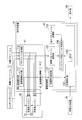
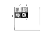
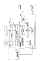
- FIG. 1 is a block diagram of a schematic configuration of a color correction device and a color conversion device according to an embodiment. It is the figure which showed an example of the reference
- FIG. 1 is a block diagram of a schematic configuration of a PC including a correction coefficient calculation unit and a color conversion device according to the present embodiment, and a display device including an image conversion unit. It is a block diagram of schematic structure of a display apparatus provided with PC provided with the setting part which concerns on this embodiment, and an image conversion part.
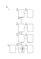
- FIG. 1 is a schematic configuration diagram of a display system 1 according to the present embodiment.
- the display system 1 includes color correction devices 10-1 to 10-n (n is an integer of 1 or more), a color conversion device 20, and display units 40-1 to 40-n. Is done.
- the color correction devices 10-1 to 10-n are not specified, they are referred to as the color correction device 10, and when not specified among the display units 40-1 to 40-n, the display unit 40 is used. That's it.
- the display unit 40 is, for example, a liquid crystal panel.
- the display element mounted on the display unit 40 is a display element other than a liquid crystal type, such as an organic electroluminescence display element, an inorganic electroluminescence display element, PALC (Plasma Address Liquid Crystal), PDP (Plasma Display Panel). Or FED (Field Emission Display).
- the display unit 40 includes a backlight and a backlight driving unit (not shown).
- the color conversion device 10-1 and the display unit 40-1 are connected to the color correction device 10-1.
- the connection between the color correction device 10-1 and the color conversion device 20 may be a wired connection or a wireless connection.
- the color correction device 10-1 creates correction data (print characteristic data and display correction data) for correcting the input video signal so as to have the same display characteristics as the printed matter, based on various pieces of input information. Then, the color correction apparatus 10-1 corrects the input video signal using the generated print characteristic data and display correction data, and displays the corrected video signal on the display unit 40-1.
- the color correction device 10-1 creates print characteristic data using the image data whose color space is converted by the color conversion device 20.
- the various types of information include rendering intent information, image profile information, and print profile information.
- Display units 40-2 to 40-n are connected to the color correction apparatuses 10-2 to 10-n, respectively.
- Each of the color correction apparatuses 10-2 to 10-n receives the print characteristic data information and the image profile created by the color correction apparatus 10-1, and receives an input video signal based on the received print characteristic data information and the image profile.
- Create correction data display correction data
- Each of the color correction apparatuses 10-2 to 10-n corrects an input video signal using the created display correction data and displays the corrected video signal on the display unit 40-1.
- the color correction apparatus 10 and the display part 40 may be integrated.
- the rendering intent information is information describing what intention (intent) the color space conversion is performed.
- the ICC profile provides three color conversion tables for perceptual, colorimetric, and saturation-oriented processing when the color reproduction region becomes narrow during conversion.
- the image profile information is a profile corresponding to an image displayed on the display unit 40.
- image profile information such as sRGB, AdobeRGB, NTSC, and DCI.
- the print profile information (output profile information) is a profile corresponding to a printing apparatus (not shown).
- There are various standards for print profile information such as Japan Color, SWOP, and EuroPress.
- the display profile information is a profile corresponding to the color correction device 10.
- the display profile information is information indicating the characteristics of the color correction device 10 used for the preview, and is different for each individual display unit 40.
- the profile information is data describing the relationship between the image, the display unit 40, and the digital values and colors of the printing apparatus.
- Profile information includes, for example, the mutual relationship between the RGB color space and the CMYK color space, the mutual relationship between the RGB (or sRGB) color space and the CIE XYZ color space, and the mutual relationship between the CMYK color space and the CIELAB color space. Etc. are included. In the present embodiment, a case will be described in which a preview of a printed material on which an image of the sRGB standard is printed according to the Japan Color standard is described.
- FIG. 2 is a block diagram of a schematic configuration of the color correction device 10 and the color conversion device 20 according to the present embodiment. As shown in FIG. 2, a color conversion device 20, a video output device 30, and a display unit 40 are connected to the color correction device 10.
- the video output device 30 outputs the video signal to the color correction device 10.
- the video output device 30 is, for example, a PC (personal computer), a portable terminal, or the like.
- the color correction apparatus 10 includes a correction coefficient calculation unit 11 and an image conversion unit 12. Further, the correction coefficient calculation unit 11 includes a reference image output unit 111, a profile reception unit 112, and a reference image decomposition unit 113.
- the color correction device 10 transmits the reference image and parameters used for color conversion to the color conversion device 20, receives the converted reference image from the color conversion device 20, and calculates color correction information from the reference image before and after conversion. To do.
- the color correction device 10 performs color correction based on the color correction information obtained by calculating the image signal input from the video output device 30 such as a personal computer or video equipment, and the display unit 40 displays the color-corrected image signal.
- the display unit 40 is an LCD (liquid crystal display), a PJ (projector), or the like, and displays an image based on an image signal subjected to color correction.
- the parameters used for color conversion include rendering intent information, image profile information corresponding to the reference image, and print profile information (output profile information) corresponding to the printing apparatus.
- the reference image output unit 111 creates the reference image shown in FIG. 3 and outputs the created reference image to the color conversion device 20 and the reference image decomposition unit 113.
- the reference image includes a total of 9 ⁇ 9 ⁇ 9 correction point colors obtained by combining, for example, nine points obtained by extracting 256 gradations (8 bits) of RGB (red, green, and blue) every 32 gradations. It is a waste.
- FIG. 3 is a diagram showing an example of the reference image in the present embodiment. As shown in FIG. 3, the reference image is an image in which color charts of 9 ⁇ 9 ⁇ 9 correction points are arranged.
- An image showing the color is arranged.
- the color chart is information indicating colors, and includes values indicating the levels (R, G, B) of the three colors red, green, and blue.
- a plurality of reference images including only the color chart of one correction point may be used instead of the reference image including the color chart of a plurality of correction points.
- the profile receiving unit 112 receives rendering intent information, image profile information selected by the user, and print profile information.
- the profile receiving unit 112 outputs the input rendering intent information, image profile information, and print profile information to the color conversion device 20.
- the profile receiving unit 112 outputs the input image profile information to the image conversion unit 12.
- the reference image decomposition unit 113 receives the reference image (FIG. 4) whose color space has been converted from the color conversion device 20, and receives the reference image (FIG. 3) from the reference image output unit 111. Further, the reference image decomposition unit 113 divides an area indicating the color included in each of the reference images before and after the color space is converted into 9 ⁇ 9 ⁇ 9 image areas, and the color for each of the divided image areas. A correction coefficient (print characteristic data) is calculated by associating it before and after conversion. The reference image decomposition unit 113 outputs the calculated print characteristic data to the image conversion unit 12.
- the print characteristic data has a 3DLIT (3 Dimension Look Up Table; 3D lookup table) configuration in which the reference image is set as the input point group and the image received from the color conversion device 20 is set as the output point group. .
- FIG. 4 is a diagram illustrating an example of a reference image obtained by converting the color space in the present embodiment.
- 9 ⁇ 9 ⁇ 9 image regions in which color conversion has been performed are arranged in the same manner as the reference image (FIG. 3).
- the color which shows the color is arrange
- the color conversion device 20 includes a color conversion engine 21 and a color conversion engine 22.
- the color conversion engine 21 uses, for example, the CMYK reference image in the sRGB color space output from the reference image decomposition unit 113 using the image profile and the print profile. To an image in the color space.
- the color conversion engine 21 converts the input reference image from the sRGB standard color space to the Japan Color standard color space.
- the color conversion engine 21 outputs a reference image color-converted to an image in the CMYK color space to the color conversion engine 22.
- the color conversion engine 22 converts the reference image in the CMYK color space output from the color conversion engine 21 into an image in the RGB color space using the image profile and the print profile output from the profile receiving unit 112.
- the color conversion engine 22 outputs the reference image converted into the RGB color space image to the reference image decomposition unit 113 of the color correction apparatus 10.
- the color conversion engine 22 converts the input reference image from the Japan Color standard color space to the sRGB standard color space.
- the color conversion engines 21 and 22 are commonly used applications such as Adobe's ACE, Microsoft's ICM 2.0 or WCS, Apple's ColorSync (registered trademark), or software included in the OS. is there.
- the image conversion unit 12 includes a print characteristic storage unit 121, an image profile storage unit 122, a display profile storage unit 123, a display correction data creation unit 124, and an image correction unit 125.
- the print characteristic storage unit 121 stores print characteristic data output from the reference image decomposition unit 113.
- the image profile storage unit 122 stores the image profile information output from the profile receiving unit 112.
- the display profile storage unit 123 stores a display profile including the display characteristics, color gamut, white point, and gamma characteristics of the display unit 40 connected to the color correction apparatus 10.
- the display profile storage unit 123 may store display characteristic information. In this case, the image conversion unit 12 may create a display profile using the display characteristics stored in the display profile storage unit 123.
- the display correction data creation unit 124 reads the image profile stored in the image profile storage unit 122 and reads the display profile stored in the display profile storage unit 123. Then, the display correction data creation unit 124 is based on the image profile describing the relationship for converting from the RGB color space to the CIE XYZ color space and the display profile describing the relationship for converting from the CIE XYZ color space to the RGB color space.
- the display correction data is created by a known method.
- the display correction data can be converted into different RGB color spaces.
- the display correction data creation unit 124 outputs the created display correction data to the image correction unit 125.
- the image correction unit 125 includes a 3DLUT (3 Dimension Look Up Table; 3D lookup table) 1251.
- the image correction unit 125 reads the print characteristic data stored in the print characteristic storage unit 121 and receives the display correction data output from the display correction data creation unit 124.
- the image correction unit 125 creates a correction coefficient using the print characteristic data and the display correction data, and sets the created correction coefficient in the 3DLUT 1251.
- the image correction unit 125 corrects the input video signal based on the 3DLUT 1251 and outputs the corrected video signal to the display unit 40.
- the image correction unit 125 may include a gamma correction unit (1DLUTx3) and a backlight driving unit.
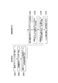
- FIG. 5 is a flowchart of a processing procedure performed by the color correction apparatus 10 and the color conversion apparatus 20 according to the present embodiment.
- the profile receiving unit 112 receives an image profile (for example, sRGB standard data).
- the profile receiving unit 112 receives a print profile (for example, data of the Japan Color standard).
- the reference image output unit 111 creates a reference image.
- the reference image to be created is an image representing correction points of the color correction device 10.
- the reference image output unit 111 outputs the created reference image to the color conversion engine 21 of the color conversion device 20.
- Step S5 The color conversion engine 21 uses the image profile and the print profile based on the rendering intent information output from the profile receiving unit 112, for example, the reference image in the RGB color space output by the reference image decomposition unit 113. Is converted into an image in a CMYK color space, for example.
- Step S6 The color conversion engine 22 converts the reference image in the CMYK color space output from the color conversion engine 21 into an image in the RGB color space using the image profile and the print profile output from the profile receiving unit 112. To do.
- the color conversion engine 22 outputs the reference image converted into the RGB color space image to the reference image decomposition unit 113 of the color correction apparatus 10.
- Step S ⁇ b> 7 The reference image decomposition unit 113 receives the reference image whose color space has been converted from the color conversion device 20.
- Step S8 The reference image decomposition unit 113 divides an area indicating the color included in each of the reference images before and after the color space is converted into 9 ⁇ 9 ⁇ 9 image areas, and for each of the divided image areas.
- print characteristic data that is a correction coefficient is created by associating with each other before and after color conversion.
- Step S ⁇ b> 9 The reference image decomposition unit 113 outputs the created print characteristic data to the image conversion unit 12.
- Step S ⁇ b> 10 The image conversion unit 12 creates a display profile using the display characteristics stored in the display profile storage unit 123.
- Step S11 The display correction data creation unit 124 creates display correction data based on the image profile read from the image profile storage unit 122 and the display profile read from the display profile storage unit 123.
- Step S12 The image correction unit 125 reads the print characteristic data stored in the print characteristic storage unit 121, and receives the display correction data output from the display correction data creation unit 124. Next, the image correction unit 125 creates a correction coefficient using the print characteristic data and the display correction data, and sets the created correction coefficient in the 3DLUT 1251. (Step S13) The image correcting unit 125 corrects the input video signal based on the 3DLUT 1251, and outputs the corrected video signal to the display unit 40. Above, the process which the color correction apparatus 10 and the color conversion apparatus 20 perform is complete
- the image quality setting according to the printed matter for the color correction device 10-1 is completed by the processing of steps S1 to S13. As a result of this processing, the created print characteristic data and display correction data are stored in the color correction apparatus 10-1.
- the color correction apparatus 10-1 includes the correction coefficient calculation unit 11 and the image conversion unit 12, and the color correction apparatuses 10-2 to 10-n include the setting unit 13 and the image conversion unit 12. As described above, all the color correction apparatuses 10 may include the correction coefficient calculation unit 11, the setting unit 13, and the image conversion unit 12.
- the correction coefficient calculation unit includes a reference image output unit that generates a reference image, image information that indicates color characteristics related to an image displayed on the display unit, and print information that indicates color characteristics related to a printing apparatus. , And a reference image decomposing unit that creates print characteristic data in which the reference image and the reference image color-converted based on the print information and the image information are associated with each other.
- the image conversion unit of the present embodiment generates display correction data based on display information indicating color characteristics related to the display unit and image information indicating color characteristics related to an image displayed on the display unit.
- a print characteristic storage unit for receiving print characteristic data created by associating a copy unit, a reference image, print information indicating color characteristics relating to the printing apparatus, and a reference image color-converted based on the image information, and display correction
- An image correction unit that generates color correction information based on the data and the print characteristic data, and performs color correction on an input image signal based on the generated color correction information.
- the color correction apparatus is a color correction apparatus that includes a correction coefficient calculation unit and an image conversion unit, and the correction coefficient calculation unit displays a reference image output unit that generates a reference image and a display unit.
- a profile receiving unit that receives image information indicating color characteristics related to the image to be printed, print information indicating color characteristics related to the printing apparatus, a reference image, and a reference image color-converted based on the print information and the image information.
- a reference image decomposition unit that creates associated print characteristic data, and the image conversion unit includes display information indicating color characteristics related to the display unit and image information indicating color characteristics related to an image displayed on the display unit.
- a display correction data generation unit that generates display correction data based on the reference image, a reference image, and a reference image that is color-converted based on print information and image information indicating color characteristics related to the printing apparatus.
- a print characteristic storage unit that receives print characteristic data created in association with each other, color correction information is created based on display correction data and print characteristic data, and is input based on the created color correction information
- An image correction unit that performs color correction on the image signal.
- the correction coefficient calculation unit of the present embodiment can create print characteristic data.
- the image conversion unit of the present embodiment can create display correction data.
- the color correction apparatus according to the present embodiment can create print attribute data and display correction data, the color correction according to the printing apparatus can be performed on the input image signal.
- FIG. 6 is a block diagram of a schematic configuration of the color correction apparatus 10A according to the present embodiment. As shown in FIG. 6, a video output device 30 and a display unit 40 are connected to the color correction device 10A. In addition, about the function part which has the same function as the color correction apparatus 10, the description is abbreviate
- the color correction device 10 ⁇ / b> A includes a setting unit 13 and an image conversion unit 12. Further, the setting unit 13 includes a data receiving unit 131 and a display setting unit 132. Similarly to the color correction apparatus 10, the image conversion unit 12 includes a print characteristic storage unit 121, an image profile storage unit 122, a display profile storage unit 123, a display correction data creation unit 124, and an image correction unit 125.
- the data receiving unit 131 receives the image profile information and the print characteristic data information from the color correction apparatus 10-1, and outputs the received image profile information and the print characteristic data information to the display setting unit 132.
- the data receiving unit 131 receives and transmits image profile information and printing characteristic data information via a recording medium such as wireless communication, wired communication, or USB (Universal Serial Bus). Also good.
- the display setting unit 132 stores the print characteristic data information output from the data receiving unit 131 in the print characteristic storage unit 121 of the image conversion unit 12.
- the display setting unit 132 stores the image profile information output from the data receiving unit 131 in the image profile storage unit 122.
- FIG. 7 is a flowchart of a processing procedure performed by the setting unit 13 and the image conversion unit 12 according to the present embodiment.
- the data receiving unit 131 receives image profile information from the color correction apparatus 10-1.
- the data receiving unit 131 receives print characteristic data information from the color correction apparatus 10-1.
- Step S ⁇ b> 103 The display setting unit 132 stores the print characteristic data information output from the data receiving unit 131 in the print characteristic storage unit 121 of the image conversion unit 12. Next, the display setting unit 132 causes the image profile storage unit 122 to store the image profile information output from the data reception unit 131.
- Step S104 The image conversion unit 12 creates a display profile based on the characteristics of the display unit, and stores the created display profile in the display profile storage unit 123.
- the display profile may be stored in the display profile storage unit 123 in advance.
- Step S ⁇ b> 105) The display correction data creation unit 124 creates display correction data based on the print characteristic data read from the print characteristic storage unit 121 and the display profile read from the display profile storage unit 123.
- the display correction data created by the display correction data creation unit 124 in step S105 is, for example, displayed on the display unit 40-2 connected to the color correction device 10-2 when the color correction device 10-2 performs processing. Since it is the data of the combined characteristics, it may be different from the display correction data created by the color correction device 10-1 in step S11.
- Step S106 The image correction unit 125 generates a correction coefficient using the print characteristic data and the display correction data, and sets the generated correction coefficient in the 3DLUT 1251.
- Step S107 The image correcting unit 125 corrects the input video signal based on the 3DLUT 1251, and outputs the corrected video signal to the display unit 40. Above, the process which the setting part 13 and the image conversion part 12 perform is complete
- the image quality setting according to the printed matter for the color correction apparatus 10-n is completed.
- the administrator of the color correction apparatuses 10-1 to 10-n sets the image quality according to the printed material for the n color correction apparatuses 10 through the processes of steps S1 to S13 and steps S101 to S107 described above. It can be performed.
- the color correction apparatus is a color correction apparatus including a setting unit and an image conversion unit
- the setting unit includes a reference image, print information indicating color characteristics related to the printing apparatus, and a display unit.
- Print characteristic data created by associating a reference image color-converted based on image information indicating color characteristics related to an image displayed on the image, and created by the other color correction device from the other color correction device
- a data reception unit that receives the print characteristic data and the image information
- a display setting unit that outputs the print characteristic data and the image information received by the data reception unit to the image conversion unit.
- Display correction data creating unit for creating display correction data based on display information indicating color characteristics relating to the image and image information received from the setting unit, and print characteristic data from the setting unit.
- An image correction unit that creates color correction information based on display correction data and print characteristic data, and performs color correction on an input image signal based on the created color correction information And comprising.
- the present embodiment even if there are a plurality of color correction apparatuses 10, only one color conversion apparatus 20 having the color conversion engines 21 and 22 may be used.
- the other color correction device receives print characteristic data created by the color conversion device 20 having the color conversion engines 21 and 22.
- the color conversion engine is realized by software, only one license is required, and thus the cost of the display system 1 can be significantly reduced.
- FIG. 8 is a schematic configuration diagram of a display system 1A according to the present embodiment.
- the color correction apparatus 10-1 includes a transmission unit 14. 8 shows an example in which the color conversion device 20 is connected to the color correction device 10-1, but the color conversion device 20 is connected to any of the color correction devices 10-1 to 10-n.
- the apparatus may be used.
- Each of the color correction apparatuses 10-1 to 10-n is connected via the network 50.
- the network 50 is a wired network or a wireless network.
- the transmission unit 14 transmits the image profile information received by the data reception unit 131 and the print characteristic data created by the correction coefficient calculation unit 11 to the other color correction apparatuses 10-2 to 10-n via the network 50. To do. Each of the color correction apparatuses 10-2 to 10-n may acquire image profile information via the network 50.
- the color correction apparatus 10-1 transmits a rendering intent via the network 50.
- Information, image quality profile information, and print profile information are acquired.
- the color correction device 10-1 creates print characteristic data, display correction data, and correction coefficients.
- the color correction apparatus 10-1 transmits the created print characteristic data and the acquired image profile information to the color correction apparatuses 10-2 to 10-n via the network 50.
- Each of the color correction apparatuses 10-2 to 10-n is created based on the received print characteristic data and image profile information, and the characteristics of the display units 40-2 to 40-3 connected to the color correction apparatuses 10. Display correction data and correction coefficients are created based on the display profile information.
- the color correction apparatus 10 acquires the rendering intent information, the image profile information, and the print profile information at the time of startup, for example.
- the present invention is not limited to this.
- the color correction apparatus 10 needs to acquire rendering intent information, image profile information, and printing profile information for each printing apparatus.
- the rendering intent information, the image profile information, and the print profile information are color-corrected via a network from a terminal used by the administrator. You may make it transmit to the apparatus 10.
- the predetermined color correction apparatus 10 may execute the processes of steps S1 to S13 described above at the timing of receiving these pieces of information.
- the color conversion engine does not need to be installed on a plurality of PCs connected to the display device (the color correction device 10 and the display unit 40), and may be installed only on one PC. . For this reason, according to this embodiment, since the license fee for one PC is sufficient, the cost of the display system 1 (or 1B) can be greatly reduced.
- each display device after transmitting a single correction data to a plurality of display devices (the color correction device 10 and the display unit 40), each display device (the color correction device 10 and the display unit 40) receives the correction data. Since the correction data is further corrected in accordance with each display unit 40, the display characteristics of a plurality of display devices can be matched.
- the color correction apparatus 10 performs the correction created using the print characteristic data
- the present invention is not limited to this. Since the print characteristic data and the display correction data are separated and stored in the color correction apparatus 10, the color correction apparatus 10 uses the display correction data and whether or not to reflect the print characteristic data. Accordingly, the user may switch and use it accordingly. Thereby, according to this embodiment, the color change accompanying printing (difference between the original display characteristic and the printing characteristic) can be confirmed by instantaneously switching the display characteristic of the display.
- the color correction apparatus 10 has described an example in which the image profile, the print characteristic data, and the display correction data are stored one by one.
- the color correction apparatus 10 may store a plurality of sets of image profiles, print characteristic data, and display correction data. Then, the user may switch and use the stored settings according to the business.
- a plurality of units 40 may be provided.
- the image conversion unit 12 of the color correction device 10 creates display profile information for each display unit 40 and uses the created plurality of display profiles to display the display unit. Display correction data for every 40 may be created. Then, the color correction apparatus 10 may correct the input image signal using the created display correction data for each display unit 40 and display the corrected image signal on each display unit 40.
- the color correction apparatus 10 when two display units 40 are connected to the color correction apparatus 10, it may be possible to select whether or not to reflect the print characteristic data for each display unit 40 as described above. For example, an image reflecting print characteristic data may be displayed on one display unit 40, and an image not reflecting print characteristic data may be displayed on the other display unit 40.
- the reference image output unit 111 is configured to output a reference image in which 256 gradations of RGB are extracted every 32 gradations.
- the correction point may be changed according to the image signal to be output.
- any one of color evaluation patterns such as ISO12646, GRACoL206, and FOGRA39 may be selected by the user, and the reference image may be generated based on the selected color evaluation pattern.
- the conversion error in the color conversion device 20 can be reflected in the correction point by the image characteristic corresponding to the design of the image signal, the purpose of use, etc., and the error in the color conversion can be suppressed.
- the image characteristics include, for example, that there are many dark parts with black as the center in an image signal based on a movie film.
- a reference image may be generated by placing importance on colors with high human visibility such as skin color, that is, by arranging a large number of correction points in a color close to skin color. Thereby, it is possible to improve the reproducibility of the print preview for a printed matter such as a photograph of a person.
- the reference image output unit 111 includes a reference image including 9 ⁇ 9 ⁇ 9 correction point colors in total, which is a combination of 9 points obtained by extracting 256 gradations (8 bits) of RGB every 32 gradations, A reference image with only gray that changes from black to white as a correction point is generated, and a reference image is displayed by the user when performing a print preview of a black-and-white print including gray and when performing a print preview of a color print. May be selected. Thereby, a print preview according to the printed matter can be performed, and reproducibility can be improved.
- the color conversion device 20 performs the reference image from the RGB value of the sRGB standard to the CMYK value of the JapanColor standard, and from the CMYK value of the JapanColor standard to the RGB value of the color space of the display device 4 by performing color conversion twice.
- the color conversion device 20 converts color information dependent on input / output devices such as RGB and CMYK into PCS information in a color space independent of the input / output devices, and converts the PCS information into color information dependent on the input / output devices. You may make it convert.
- the PCS standard indicates a profile combined color space, and indicates a color space independent of input / output devices such as display devices such as Lab and XYZ, and printing devices.
- the reference image including 9 ⁇ 9 ⁇ 9 color charts as correction points has been described.
- the present invention is not limited to this, and the number of correction points is determined according to the storage capacity of the 3DLUT 1251. May be changed.
- the case where the color of the printed matter output by the printing apparatus is reproduced on the display unit 40 has been described.
- the present invention is not limited to this, and the color of the output apparatus that outputs an image other than the printing apparatus is used. You may make it reproduce on the display part 40.
- the color of an image displayed by a display device different from the display unit 40 for example, a projector may be reproduced on the display unit 40 (LCD display).
- profile information corresponding to the output device may be used instead of the print profile information.
- the display profile storage unit 123 may use a standard value such as “2.2” as the gamma characteristic stored in advance.
- the display profile information stored in the display profile storage unit 123 includes a standard gamma characteristic represented by a standard value or a gamma correction value for adjusting the display unit 40 to the standard gamma characteristic.
- the 3DLUT 1251 may calculate an additional correction value based on color vision abnormalities and different color vision characteristics such as the CIE1964X10Y10Z10 color system, and may perform color correction on the color of each pixel of the input image signal.
- one color correction device 10 includes the correction coefficient calculation unit 11 and the image conversion unit 12, and the other color correction device 10 includes the setting unit 13 and the image conversion unit 12.
- the correction coefficient calculation unit 11 or the setting unit 13 may be provided in the PC, and the image conversion unit 12 may be provided in the display device.
- FIG. 9 is a block diagram of a schematic configuration of a PC 301 including the correction coefficient calculation unit 11 and the color conversion device 20 and a display device 302 including the image conversion unit 12 according to the present embodiment.
- a display device 302 is connected to the PC 301.
- the PC 301 includes a correction coefficient calculation unit 11, a color conversion device 20, and a video output unit 3011.
- the display device 302 includes the image conversion unit 12 and the display unit 40.
- the components of the correction coefficient calculation unit 11, the color conversion device 20, and the image conversion unit 12 are the same as those of the color correction device 10 (FIG. 10).
- the PC 301 and the display device 302 are connected via a cable capable of exchanging information.
- the cable is, for example, a USB cable.
- information may be exchanged via a video cable connecting the PC 301 and the display device 302.
- the correction coefficient calculation unit 11 and the color conversion apparatus 20 of the PC 301 create print characteristic data using the acquired rendering intent information, image profile information, and print profile information, and the created reference image.
- the PC 301 acquires rendering intent information, image profile information, and print profile information, for example, via a network or a recording medium connected to a USB terminal or the like.
- the correction coefficient calculation unit 11 outputs the created print characteristic data and the acquired image profile information to the display device 302. Further, the PC 301 outputs a video signal created by the PC 301 from the video output unit 3011 to the display device 302. Further, the PC 301 outputs the created print characteristic data to another PC via the network.
- the image conversion unit 12 of the display device 302 uses the image profile information output from the PC 301 and the display profile information created by the own device to create display correction data that matches the display unit 40 of the own display device 312.
- the image conversion unit 12 creates a correction coefficient using the received print characteristic information and the created display correction data, and sets the created correction coefficient in the 3DLUT 1251.
- the image conversion unit 12 corrects the video signal input from the PC 301 based on the 3DLUT 1251 and outputs the corrected video signal to the display unit 40.
- FIG. 10 is a block diagram of a schematic configuration of a PC 301 including the setting unit 13 and a display device 302 including the image conversion unit 12 according to the present embodiment.
- a display device 312 is connected to the PC 311.
- the PCs 301 to 311 include a setting unit 13 and a video output unit 3101.
- the display device 312 includes the image conversion unit 12 and the display unit 40.
- the setting unit 13 of the PC 311 receives image profile information and print characteristic data information output from the PC 301 via, for example, a network.
- the setting unit 13 outputs the received print characteristic data information to the display device 312.
- the setting unit 13 outputs the received image profile information to the display device 312.
- the PC 311 outputs the video signal created by the PC 311 from the video output unit 3101 to the display device 312.
- the image conversion unit 12 of the display device 312 creates display correction data that matches the display unit 40 of the display device 312, similarly to the image conversion unit 12 of the display device 302.
- the image conversion unit 12 creates a correction coefficient using the received print characteristic information and the created display correction data, and sets the created correction coefficient in the 3DLUT 1251.
- the image conversion unit 12 corrects the video signal input from the PC 311 based on the 3DLUT 1251 and outputs the corrected video signal to the display unit 40.
- the other PC may be the PC 311 including the setting unit 13 illustrated in FIG.
- the PC 311 other than the PC 301 receives the image profile information and the print characteristic data information output from the PC 301 via the network, and outputs the received image profile information and print characteristic data information to the connected display device 312. .
- the image conversion unit 12 of the display device 312 connected to each PC 311 corrects the video signal input from the PC 311 based on the 3DLUT 1251, and outputs the corrected video signal to the display unit 40.
- the PC 301 includes the color conversion device 20, and the display device 302 and the plurality of display devices 312 can perform image quality settings according to the printed matter.
- the color correction device 10A in FIG. 6, the correction coefficient calculation unit 11 and the color conversion device 20 in FIG. 9, and the image conversion unit 12 in FIG. The above program may be recorded on a computer-readable recording medium, the program recorded on the recording medium may be read into a computer system, and executed to execute the processing of each unit.
- the “computer system” includes an OS and hardware such as peripheral devices. Further, the “computer system” includes a homepage providing environment (or display environment) if a WWW system is used.
- the “computer-readable recording medium” is a portable medium such as a flexible disk, a magneto-optical disk, a ROM (Read Only Memory), a CD-ROM, or a USB (Universal Serial Bus) I / F (interface).
- a storage device such as a USB memory or a hard disk built in a computer system.
- the “computer-readable recording medium” includes a medium that holds a program for a certain period of time, such as a volatile memory inside a computer system serving as a server or a client.
- the program may be a program for realizing a part of the functions described above, and may be a program capable of realizing the functions described above in combination with a program already recorded in a computer system.
Landscapes
- Engineering & Computer Science (AREA)
- Multimedia (AREA)
- Signal Processing (AREA)
- Facsimile Image Signal Circuits (AREA)
- Image Processing (AREA)
- Color Image Communication Systems (AREA)
Abstract
Description
図1は、本実施形態に係る表示システム1の概略構成図である。
図1に示すように、表示システム1は、色補正装置10-1~10-n(nは1以上の整数)、色変換装置20、及び表示部40-1~40-nを含んで構成される。なお、以下の説明において、色補正装置10-1~10-nのうち特定しない場合は、色補正装置10といい、表示部40-1~40-nのうち特定しない場合は、表示部40という。
なお、図1では、色補正装置10と表示部40とが、分離している例を説明したが、色補正装置10と表示部40とは、一体型であってもよい。
レンダリングインテント(Rendering Intent)情報とは、色空間の変換をどのような意図(インテント)で行うかが記述される情報である。例えばICCプロファイルには、色再現領域が変換時に狭くなる場合の処理について、知覚的、測色的、彩度重視の3つの色変換テーブルが用意されている。
画像プロファイル情報とは、表示部40に表示する画像に対応するプロファイルである。画像プロファイル情報は、sRGB、AdobeRGB、NTSC、DCIなどの様々な規格が存在する。
印刷プロファイル情報(出力プロファイル情報)とは、不図示の印刷装置に対応するプロファイルである。印刷プロファイル情報は、Japan Color、SWOP、EuroPressなどの様々な規格が存在する。
表示プロファイル情報とは、色補正装置10に対応するプロファイルである。表示プロファイル情報は、プレビューに使用する色補正装置10の特性を示す情報であり、表示部40の個体ごとに異なる。
色変換エンジン21は、プロファイル受信部112が出力したレンダリングインテント情報に基づいて、画像プロファイル及び印刷プロファイルを用いて、基準画像分解部113が出力した例えばsRGBの色空間における基準画像を、例えばCMYKの色空間における画像に変換する。例えば、色変換エンジン21は、入力された基準画像をsRGB規格の色空間からJapan Color規格の色空間に変換を行う。色変換エンジン21は、CMYKの色空間の画像に色変換された基準画像を、色変換エンジン22に出力する。
印刷特性記憶部121には、基準画像分解部113が出力した印刷特性データが記憶される。
画像プロファイル記憶部122には、プロファイル受信部112が出力した画像プロファイル情報が記憶される。
表示プロファイル記憶部123には、色補正装置10に接続される表示部40の表示特性、色域、白点、ガンマ特性を含む表示プロファイルが記憶される。なお、表示プロファイル記憶部123には、表示特性情報が記憶されていてもよい。この場合、画像変換部12は、表示プロファイル記憶部123に記憶区されている表示特性を用いて、表示プロファイルを作成するようにしてもよい。
(ステップS1)プロファイル受信部112は、画像プロファイル(例えば、sRGB規格のデータ)を受け取る。
(ステップS2)プロファイル受信部112は、印刷プロファイル(例えば、Japan Color規格のデータ)を受け取る。
(ステップS4)基準画像出力部111は、作成した基準画像を色変換装置20の色変換エンジン21に出力する。
(ステップS8)基準画像分解部113は、色空間が変換される前後の基準画像それぞれに含まれる色を示す領域を9×9×9個の画像領域に分割し、分割した画像領域それぞれに対して色変換される前後ごとに対応付けることで、補正係数である印刷特性データを作成する。
(ステップS9)基準画像分解部113は、作成した印刷特性データを、画像変換部12に出力する。
(ステップS11)ディスプレイ補正データ作成部124は、画像プロファイル記憶部122から読み出した画像プロファイルと、表示プロファイル記憶部123から読み出した表示プロファイルに基づいてディスプレイ補正データを作成する。
(ステップS13)画像補正部125は、3DLUT1251に基づいて入力された映像信号を補正し、補正した映像信号を表示部40に出力する。
以上で、色補正装置10及び色変換装置20が行う処理を終了する。
また、本実施形態の画像変換部は、表示部に関する色特性を示す表示情報と、表示部に表示する画像に関する色特性を示す画像情報と、に基づいてディスプレイ補正データを作成するディスプレイ補正データ作成部と、基準画像と、印刷装置に関する色特性を示す印刷情報および画像情報に基づいて色変換された基準画像と、を対応付けて作成された印刷特性データを受け取る印刷特性記憶部と、ディスプレイ補正データと印刷特性データとに基づいて色補正情報を作成し、作成した色補正情報に基づいて、入力される画像信号に対して色補正を行う画像補正部と、を備える。
また、本実施形態の色補正装置は、印刷属性データ及びディスプレイ補正データを作成することができるので、入力された画像信号に対して印刷装置に合わせた色補正を行うことができる。
図6は、本実施形態に係る色補正装置10Aの概略構成のブロック図である。図6に示すように色補正装置10Aには、映像出力装置30、及び表示部40が接続される。なお、色補正装置10と同じ機能を有する機能部については、同じ符号を用いて、説明を省略する。
(ステップS101)データ受信部131は、色補正装置10-1から画像プロファイル情報を受け取る。
(ステップS102)データ受信部131は、色補正装置10-1から印刷特性データ情報を受け取る。
(ステップS105)ディスプレイ補正データ作成部124は、印刷特性記憶部121から読み出した印刷特性データと、表示プロファイル記憶部123から読み出した表示プロファイルに基づいて、ディスプレイ補正データを作成する。なお、本ステップS105においてディスプレイ補正データ作成部124が作成するディスプレイ補正データは、例えば、色補正装置10-2が処理を行う場合、色補正装置10-2に接続される表示部40-2に合わせた特性のデータであるため、ステップS11において色補正装置10-1が作成したディスプレイ補正データとは異なっている場合もある。
(ステップS107)画像補正部125は、3DLUT1251に基づいて入力された映像信号を補正し、補正した映像信号を表示部40に出力する。
以上で、設定部13及び画像変換部12が行う処理を終了する。
図8は、本実施形態に係る表示システム1Aの概略構成図である。図8に示すように、色補正装置10-1は、送信部14を備えている。なお、図8では、色変換装置20が色補正装置10-1に接続される例を示したが、色変換装置20が接続されるのは、色補正装置10-1~10-nのいずれの装置であってもよい。なお、色補正装置10-1~10-nそれぞれは、ネットワーク50を介して接続される。ネットワーク50は、有線メットワーク、または無線ネットワークである。
なお、色補正装置10-2~10-nそれぞれは、画像プロファイル情報を、ネットワーク50を介して取得するようにしてもよい。
さらに、本実施形態によれば、色変換エンジンは、表示装置(色補正装置10と表示部40)に接続される複数のPCにインストールする必要がなく、1台のPCのみにインストールすればよい。このため、本実施形態によれば、1台のPCに対するライセンス料で済むため、表示システム1(または1B)のコストを大幅に削減することができる。
また、基準画像出力部111は、RGBそれぞれの256階調(8ビット)を32階調おきに抽出した9点を組み合わせた合計9×9×9点の補正点の色を含む基準画像と、黒から白に変化するグレーのみを補正点とした基準画像とを生成し、グレーを含む白黒の印刷物の印刷プレビューを行う場合と、カラーの印刷物の印刷プレビューを行う場合とにおいて利用者により基準画像を選択できるようにしてもよい。これにより、印刷物に応じた印刷プレビューを行うことができ、再現性を高めることができる。
また、上述した実施形態では、印刷装置が出力する印刷物の色味を表示部40上で再現する場合について説明したが、これに限らず、印刷装置以外の画像を出力する出力装置の色味を表示部40上で再現するようにしてもよい。表示部40とは別の表示装置、例えば、プロジェクタにより映し出される画像の色味を表示部40(LCDディスプレイ)上に再現するようにしてもよい。この場合、印刷プロファイル情報に替えて、出力装置に対応するプロファイル情報を用いてもよい。
図9に示すように、PC301には表示装置302が接続される。また、PC301は、補正係数算出部11、色変換装置20、及び映像出力部3011を備える。また、表示装置302は、画像変換部12及び表示部40を備える。なお、補正係数算出部11、色変換装置20、及び画像変換部12の各構成は、色補正装置10(図10)の各部と同様である。
なお、PC301と表示装置302とは、情報のやりとりが可能なケーブルを介して接続される。ケーブルは、例えばUSBケーブルである。または、PC301と表示装置302とを接続する映像ケーブルを介して、情報のやりとりを行うようにしてもよい。
また、PC301は、ネットワークを介して、作成した印刷特性データを他のPCに出力する。
図10に示すように、PC311には表示装置312が接続される。また、PC301から311は、設定部13及び映像出力部3101を備える。表示装置312は、表示装置302と同様に、画像変換部12及び表示部40を備える。
PC301以外のPC311は、ネットワークを介して、画像プロファイル情報と、PC301が出力する印刷特性データ情報を受け取り、受け取った画像プロファイル情報と印刷特性データ情報とを、接続されている表示装置312に出力する。そして、PC311それぞれに接続される表示装置312の画像変換部12は、3DLUT1251に基づいてPC311から入力された映像信号を補正し、補正した映像信号を表示部40に出力する。
このように、本実施形態によれば、PC301のみが色変換装置20を備えるだけで、表示装置302及び複数の表示装置312を、印刷物に合わせた画質設定を行うことができる。
また、「コンピュータシステム」は、WWWシステムを利用している場合であれば、ホームページ提供環境(あるいは表示環境)も含むものとする。
また、「コンピュータ読み取り可能な記録媒体」とは、フレキシブルディスク、光磁気ディスク、ROM(Read Only Memory)、CD-ROM等の可搬媒体、USB(Universal Serial Bus) I/F(インタフェース)を介して接続されるUSBメモリ、コンピュータシステムに内蔵されるハードディスク等の記憶装置のことをいう。さらに「コンピュータ読み取り可能な記録媒体」とは、サーバやクライアントとなるコンピュータシステム内部の揮発性メモリのように、一定時間プログラムを保持しているものも含むものとする。また上記プログラムは、前述した機能の一部を実現するためのものであっても良く、さらに前述した機能をコンピュータシステムにすでに記録されているプログラムとの組み合わせで実現できるものであってもよい。
Claims (9)
- 基準画像を生成する基準画像出力部と、
表示部に表示する画像に関する色特性を示す画像情報と、印刷装置に関する色特性を示す印刷情報と、を受け取るプロファイル受信部と、
前記基準画像と、前記印刷情報および前記画像情報に基づいて色変換された前記基準画像と、を対応付けた印刷特性データを作成する基準画像分解部と、
を備えることを特徴とする補正係数算出部。 - 前記画像情報は、
前記表示部に表示する画像に対応する色特性を示す画像プロファイル情報を含み、
前記印刷情報は、
前記印刷装置に対応する色特性を示す印刷プロファイル情報と、前記色変換における色空間変換の方法を示すレンダリングインテントとを含む
ことを特徴とする請求項1に記載の補正係数算出部。 - 表示部に関する色特性を示す表示情報と、前記表示部に表示する画像に関する色特性を示す画像情報と、に基づいてディスプレイ補正データを作成するディスプレイ補正データ作成部と、
基準画像と、印刷装置に関する色特性を示す印刷情報および前記画像情報に基づいて色変換された前記基準画像と、を対応付けて作成された印刷特性データを受け取る印刷特性記憶部と、
前記ディスプレイ補正データと前記印刷特性データとに基づいて色補正情報を作成し、作成した前記色補正情報に基づいて、入力される画像信号に対して色補正を行う画像補正部と、
を備えることを特徴とする画像変換部。 - 前記色補正は、
第1のRGBの色空間からXYZの色空間に変換し、変換されたXYZの色空間から第2のRGBの色空間に変換する
ことを特徴とする請求項3に記載の画像変換部。 - 補正係数算出部と画像変換部とを備える色補正装置であって、
前記補正係数算出部は、
基準画像を生成する基準画像出力部と、
表示部に表示する画像に関する色特性を示す画像情報と、印刷装置に関する色特性を示す印刷情報と、を受け取るプロファイル受信部と、
前記基準画像と、前記印刷情報および前記画像情報に基づいて色変換された前記基準画像と、を対応付けた印刷特性データを作成する基準画像分解部と、
を備え、
前記画像変換部は、
前記表示部に関する色特性を示す表示情報と、前記表示部に表示する画像に関する色特性を示す画像情報と、に基づいてディスプレイ補正データを作成するディスプレイ補正データ作成部と、
基準画像と、前記印刷装置に関する色特性を示す印刷情報および前記画像情報に基づいて色変換された前記基準画像と、を対応付けて作成された印刷特性データを受け取る印刷特性記憶部と、
前記ディスプレイ補正データと前記印刷特性データとに基づいて色補正情報を作成し、作成した前記色補正情報に基づいて、入力される画像信号に対して色補正を行う画像補正部と、
を備えることを特徴とする色補正装置。 - 設定部と画像変換部とを備える色補正装置であって、
前記設定部は、
基準画像と、印刷装置に関する色特性を示す印刷情報および表示部に表示する画像に関する色特性を示す画像情報に基づいて色変換された前記基準画像と、を対応付けて作成された印刷特性データであって、他の色補正装置から当該他の色補正装置が作成した前記印刷特性データと前記画像情報と、を受け取るデータ受信部と、
前記データ受信部が受信した前記印刷特性データと画像情報とを前記画像変換部に出力するディスプレイ設定部と、を備え、
前記画像変換部は、
前記表示部に関する色特性を示す表示情報と、前記設定部から受け取った前記画像情報と、に基づいてディスプレイ補正データを作成するディスプレイ補正データ作成部と、
前記設定部から前記印刷特性データを受け取る印刷特性記憶部と、
前記ディスプレイ補正データと前記印刷特性データとに基づいて色補正情報を作成し、作成した前記色補正情報に基づいて、入力される画像信号に対して色補正を行う画像補正部と、
を備えることを特徴とする色補正装置。 - 画像を表示する表示部と、
前記表示部に関する色特性を示す表示情報と、前記表示部に表示する画像に関する色特性を示す画像情報と、に基づいてディスプレイ補正データを作成するディスプレイ補正データ作成部と、
基準画像と、印刷装置に関する色特性を示す印刷情報および前記画像情報に基づいて色変換された前記基準画像と、を対応付けて作成された印刷特性データを受け取る印刷特性記憶部と、
前記ディスプレイ補正データと前記印刷特性データとに基づいて色補正情報を作成し、作成した前記色補正情報に基づいて、入力される画像信号に対して色補正を行う画像補正部と、を備え、
前記表示部は、前記色補正の行われた前記画像信号に基づく画像を表示する
ことを特徴とする表示装置。 - 基準画像を生成する基準画像出力手順と、
表示部に表示する画像に関する色特性を示す画像情報と、印刷装置に関する色特性を示す印刷情報と、を受け取るプロファイル受信手順と、
前記基準画像と、前記印刷情報および前記画像情報に基づいて色変換された前記基準画像と、を対応付けた印刷特性データを作成する基準画像分解手順と、
を含むことを特徴とする補正係数算出方法。 - 基準画像を生成する基準画像出力手順と、
表示部に表示する画像に関する色特性を示す画像情報と、印刷装置に関する色特性を示す印刷情報と、を受け取るプロファイル受信手順と、
前記基準画像と、前記印刷情報および前記画像情報に基づいて色変換された前記基準画像と、を対応付けた印刷特性データを作成する基準画像分解手順と、
をコンピュータに実行させることを特徴とするプログラム。
Priority Applications (5)
| Application Number | Priority Date | Filing Date | Title |
|---|---|---|---|
| JP2015552273A JP6312219B2 (ja) | 2013-12-13 | 2013-12-13 | 補正係数算出部、画像変換部、色補正装置、表示装置、補正係数算出方法、及びプログラム |
| US15/101,907 US9992384B2 (en) | 2013-12-13 | 2013-12-13 | Correction coefficient calculation unit, image conversion unit, color correction device, display device, correction coefficient calculation method, and program |
| PCT/JP2013/083493 WO2015087447A1 (ja) | 2013-12-13 | 2013-12-13 | 補正係数算出部、画像変換部、色補正装置、表示装置、補正係数算出方法、及びプログラム |
| CN201380081507.8A CN105814872B (zh) | 2013-12-13 | 2013-12-13 | 校正系数计算单元、图像转换单元、颜色校正设备、显示设备、校正系数计算方法和程序 |
| US15/972,560 US10594904B2 (en) | 2013-12-13 | 2018-05-07 | Correction coefficient calculation unit, image conversion unit, color correction device, display device, correction coefficient calculation method, and program |
Applications Claiming Priority (1)
| Application Number | Priority Date | Filing Date | Title |
|---|---|---|---|
| PCT/JP2013/083493 WO2015087447A1 (ja) | 2013-12-13 | 2013-12-13 | 補正係数算出部、画像変換部、色補正装置、表示装置、補正係数算出方法、及びプログラム |
Related Child Applications (2)
| Application Number | Title | Priority Date | Filing Date |
|---|---|---|---|
| US15/101,907 A-371-Of-International US9992384B2 (en) | 2013-12-13 | 2013-12-13 | Correction coefficient calculation unit, image conversion unit, color correction device, display device, correction coefficient calculation method, and program |
| US15/972,560 Continuation US10594904B2 (en) | 2013-12-13 | 2018-05-07 | Correction coefficient calculation unit, image conversion unit, color correction device, display device, correction coefficient calculation method, and program |
Publications (1)
| Publication Number | Publication Date |
|---|---|
| WO2015087447A1 true WO2015087447A1 (ja) | 2015-06-18 |
Family
ID=53370788
Family Applications (1)
| Application Number | Title | Priority Date | Filing Date |
|---|---|---|---|
| PCT/JP2013/083493 Ceased WO2015087447A1 (ja) | 2013-12-13 | 2013-12-13 | 補正係数算出部、画像変換部、色補正装置、表示装置、補正係数算出方法、及びプログラム |
Country Status (4)
| Country | Link |
|---|---|
| US (2) | US9992384B2 (ja) |
| JP (1) | JP6312219B2 (ja) |
| CN (1) | CN105814872B (ja) |
| WO (1) | WO2015087447A1 (ja) |
Families Citing this family (5)
| Publication number | Priority date | Publication date | Assignee | Title |
|---|---|---|---|---|
| US20170186403A1 (en) * | 2015-12-28 | 2017-06-29 | Printing Technology Research Institute | Method of simulating print color on mobile devices |
| US11386588B2 (en) * | 2016-12-27 | 2022-07-12 | Sony Corporation | Product design system and design image correction apparatus |
| US10602026B2 (en) * | 2017-06-20 | 2020-03-24 | Fuji Xerox Co., Ltd. | Image processing apparatus, image processing method, and non-transitory computer readable medium |
| JP7220685B2 (ja) * | 2020-03-30 | 2023-02-10 | 富士フイルム株式会社 | プリント支援装置、その作動方法、及び作動プログラム |
| CN115174876B (zh) * | 2022-04-12 | 2023-08-11 | 北京印刷学院 | 一种医用内窥镜成像颜色分析与校正用色标设计与制作方法 |
Citations (4)
| Publication number | Priority date | Publication date | Assignee | Title |
|---|---|---|---|---|
| JP2005196454A (ja) * | 2004-01-07 | 2005-07-21 | Seiko Epson Corp | プリンタ用色変換ルックアップテーブルのインストール |
| JP2006094297A (ja) * | 2004-09-27 | 2006-04-06 | Fuji Xerox Co Ltd | 画像形成装置、画像処理装置、画像処理方法及びそのプログラム |
| JP2008245024A (ja) * | 2007-03-28 | 2008-10-09 | Seiko Epson Corp | ルックアップテーブル作成 |
| JP2009117992A (ja) * | 2007-11-02 | 2009-05-28 | Fujifilm Corp | 画像データ修正装置および画像データ修正プログラム |
Family Cites Families (30)
| Publication number | Priority date | Publication date | Assignee | Title |
|---|---|---|---|---|
| JPS5231428A (en) | 1975-07-31 | 1977-03-09 | Bowles Fluidics Corp | Apparatus for cleaning window of vehicle |
| US6803921B1 (en) * | 2000-05-18 | 2004-10-12 | Xerox Corporation | Use of softproofing to assist in the rendering of images of unknown colorimetry |
| US7023448B1 (en) * | 2000-08-22 | 2006-04-04 | Adobe Systems Incorporated | Selecting rendering intent |
| JP4307095B2 (ja) | 2003-02-05 | 2009-08-05 | キヤノン株式会社 | 色変換方法及びプロファイル作成方法 |
| US20050219561A1 (en) * | 2003-11-28 | 2005-10-06 | Canon Kabushiki Kaisha | User interface for selecting color settings |
| JP4325552B2 (ja) * | 2004-12-24 | 2009-09-02 | セイコーエプソン株式会社 | 画像処理装置、画像処理方法及び画像処理プログラム |
| EP1821518B1 (en) * | 2006-02-16 | 2013-05-22 | Hewlett-Packard Development Company, L.P. | Personalized color reproduction |
| JP4656006B2 (ja) * | 2006-06-05 | 2011-03-23 | 富士ゼロックス株式会社 | 色変換装置及び色変換プログラム |
| JP4779843B2 (ja) * | 2006-07-11 | 2011-09-28 | 富士ゼロックス株式会社 | 色変換ルックアップテーブル作成装置、色変換ルックアップテーブル作成方法、及び色変換ルックアップテーブル作成プログラム |
| JP2008085980A (ja) | 2006-08-31 | 2008-04-10 | Sony Corp | 色変換装置、エミュレーション方法、三次元ルックアップテーブルの生成方法、画像処理装置 |
| US7894111B2 (en) * | 2006-12-18 | 2011-02-22 | Xerox Corporation | Method and system to determine preferred color management settings for printing documents |
| JP4910860B2 (ja) | 2007-04-20 | 2012-04-04 | 富士ゼロックス株式会社 | 画像ファイル作成装置、画像処理装置、画像処理システム、およびプログラム |
| JP4985087B2 (ja) * | 2007-05-11 | 2012-07-25 | 富士ゼロックス株式会社 | 画像処理装置、画像出力装置、画像処理システム、画像処理プログラム、及び画像出力プログラム |
| JP5043513B2 (ja) * | 2007-05-28 | 2012-10-10 | キヤノン株式会社 | 色処理装置および方法 |
| JP4974853B2 (ja) * | 2007-11-02 | 2012-07-11 | キヤノン株式会社 | 画像処理装置、画像処理方法およびプログラム |
| JP4623137B2 (ja) * | 2008-05-14 | 2011-02-02 | 富士ゼロックス株式会社 | 色処理装置、方法及びプログラム |
| JP5475402B2 (ja) * | 2008-12-22 | 2014-04-16 | キヤノン株式会社 | 画像処理装置、画像処理方法及びプログラム |
| JP5538743B2 (ja) * | 2009-04-15 | 2014-07-02 | キヤノン株式会社 | 画像処理装置及び画像処理方法及びプログラム |
| US8860751B2 (en) * | 2009-09-01 | 2014-10-14 | Entertainment Experience Llc | Method for producing a color image and imaging device employing same |
| JP2013504080A (ja) * | 2009-09-01 | 2013-02-04 | エンターテインメント イクスピアリアンス エルエルシー | カラー画像を生成する方法及び当該方法を使用した画像化装置 |
| WO2011048623A1 (ja) * | 2009-10-19 | 2011-04-28 | Necディスプレイソリューションズ株式会社 | 色補正テーブル算出回路、色補正装置及び表示装置、並びに色補正方法 |
| JP5678584B2 (ja) * | 2009-12-16 | 2015-03-04 | 株式会社リコー | 画像処理装置、画像処理方法、およびプログラム |
| JP2012029276A (ja) * | 2010-06-21 | 2012-02-09 | Ricoh Co Ltd | 画像形成装置、色調整方法及び色調整プログラム |
| JP5630112B2 (ja) * | 2010-07-15 | 2014-11-26 | 富士ゼロックス株式会社 | 色変換係数生成装置、色再現特性修正装置及びプログラム |
| KR20120016451A (ko) * | 2010-08-16 | 2012-02-24 | 삼성전자주식회사 | 인쇄 제어 단말장치 및 색상 보정 방법 |
| JP5731847B2 (ja) * | 2011-02-16 | 2015-06-10 | キヤノン株式会社 | 画像処理装置および画像処理方法 |
| JP5713727B2 (ja) * | 2011-02-25 | 2015-05-07 | キヤノン株式会社 | プロファイル作成方法、プロファイル作成装置、プロファイルにより色変換を行う画像処理装置およびプログラム |
| JP5885422B2 (ja) * | 2011-08-11 | 2016-03-15 | キヤノン株式会社 | 画像処理装置および画像処理方法 |
| JP6179567B2 (ja) * | 2015-08-17 | 2017-08-16 | コニカミノルタ株式会社 | 色検証システム及びプログラム |
| US20170110071A1 (en) * | 2015-10-15 | 2017-04-20 | Canon Kabushiki Kaisha | Image display apparatus and color conversion apparatus |
-
2013
- 2013-12-13 JP JP2015552273A patent/JP6312219B2/ja active Active
- 2013-12-13 US US15/101,907 patent/US9992384B2/en active Active
- 2013-12-13 WO PCT/JP2013/083493 patent/WO2015087447A1/ja not_active Ceased
- 2013-12-13 CN CN201380081507.8A patent/CN105814872B/zh active Active
-
2018
- 2018-05-07 US US15/972,560 patent/US10594904B2/en active Active
Patent Citations (4)
| Publication number | Priority date | Publication date | Assignee | Title |
|---|---|---|---|---|
| JP2005196454A (ja) * | 2004-01-07 | 2005-07-21 | Seiko Epson Corp | プリンタ用色変換ルックアップテーブルのインストール |
| JP2006094297A (ja) * | 2004-09-27 | 2006-04-06 | Fuji Xerox Co Ltd | 画像形成装置、画像処理装置、画像処理方法及びそのプログラム |
| JP2008245024A (ja) * | 2007-03-28 | 2008-10-09 | Seiko Epson Corp | ルックアップテーブル作成 |
| JP2009117992A (ja) * | 2007-11-02 | 2009-05-28 | Fujifilm Corp | 画像データ修正装置および画像データ修正プログラム |
Also Published As
| Publication number | Publication date |
|---|---|
| US20160360071A1 (en) | 2016-12-08 |
| US20180255209A1 (en) | 2018-09-06 |
| CN105814872B (zh) | 2019-01-08 |
| JPWO2015087447A1 (ja) | 2017-03-16 |
| US10594904B2 (en) | 2020-03-17 |
| US9992384B2 (en) | 2018-06-05 |
| CN105814872A (zh) | 2016-07-27 |
| JP6312219B2 (ja) | 2018-04-18 |
Similar Documents
| Publication | Publication Date | Title |
|---|---|---|
| Kriss | Color management: Understanding and using ICC Profiles | |
| US8027070B2 (en) | Methods and systems for hue adjustment | |
| US20030081060A1 (en) | Method and system for management of color through conversion between color spaces | |
| JP4263131B2 (ja) | 色変換方法および画像処理装置 | |
| US8204304B2 (en) | Color gamut mapping by forming curved cross-sectional surfaces | |
| JP7524681B2 (ja) | 画像処理装置、画像処理方法およびプログラム | |
| US10594904B2 (en) | Correction coefficient calculation unit, image conversion unit, color correction device, display device, correction coefficient calculation method, and program | |
| US8284447B2 (en) | Image processing apparatus and profile generating method | |
| US8456511B2 (en) | Method and apparatus for reproducing image using output prediction | |
| KR101657165B1 (ko) | 인쇄 제어 단말장치 및 색상 보정 방법 | |
| JP2016025496A (ja) | 色変換装置および色変換方法 | |
| KR20120016451A (ko) | 인쇄 제어 단말장치 및 색상 보정 방법 | |
| US8111423B2 (en) | Image processing device and image processing method | |
| KR20050109663A (ko) | 프로파일 생성 방법 및 장치 | |
| US8018619B2 (en) | Simulation of print via a network | |
| JP2005286904A (ja) | デバイスリンクプロファイルの作成方法および装置並びに画像処理装置 | |
| JP5322326B2 (ja) | 色補正テーブル算出回路、色補正装置、表示装置、色補正方法、及びプログラム | |
| JP6780442B2 (ja) | 色処理装置、色処理方法、色処理システムおよびプログラム | |
| JP2009147492A (ja) | 画像処理装置及びプログラム | |
| JP4530101B2 (ja) | ネットワークを介した印刷物のシミュレーションサービス | |
| JP5748236B2 (ja) | 色補正情報の生成方法、及び色補正装置 | |
| JP2004023650A (ja) | 画像処理装置及び該画像処理装置に用いる画像生成もしくは処理プログラム | |
| JP2006229403A (ja) | 複数の観察条件下における印刷物のシミュレーション | |
| JP2015070560A (ja) | 画像処理装置、画像処理方法、プログラムおよび記録媒体 | |
| Gorji et al. | Errors involved in profiles in color management systems |
Legal Events
| Date | Code | Title | Description |
|---|---|---|---|
| 121 | Ep: the epo has been informed by wipo that ep was designated in this application |
Ref document number: 13899258 Country of ref document: EP Kind code of ref document: A1 |
|
| WWE | Wipo information: entry into national phase |
Ref document number: 15101907 Country of ref document: US |
|
| ENP | Entry into the national phase |
Ref document number: 2015552273 Country of ref document: JP Kind code of ref document: A |
|
| NENP | Non-entry into the national phase |
Ref country code: DE |
|
| 122 | Ep: pct application non-entry in european phase |
Ref document number: 13899258 Country of ref document: EP Kind code of ref document: A1 |