WO2015083335A1 - 車両用制御装置 - Google Patents
車両用制御装置 Download PDFInfo
- Publication number
- WO2015083335A1 WO2015083335A1 PCT/JP2014/005798 JP2014005798W WO2015083335A1 WO 2015083335 A1 WO2015083335 A1 WO 2015083335A1 JP 2014005798 W JP2014005798 W JP 2014005798W WO 2015083335 A1 WO2015083335 A1 WO 2015083335A1
- Authority
- WO
- WIPO (PCT)
- Prior art keywords
- unit
- vehicle
- code
- state
- control device
- Prior art date
- Legal status (The legal status is an assumption and is not a legal conclusion. Google has not performed a legal analysis and makes no representation as to the accuracy of the status listed.)
- Ceased
Links
Images

Classifications
-
- B—PERFORMING OPERATIONS; TRANSPORTING
- B60—VEHICLES IN GENERAL
- B60R—VEHICLES, VEHICLE FITTINGS, OR VEHICLE PARTS, NOT OTHERWISE PROVIDED FOR
- B60R25/00—Fittings or systems for preventing or indicating unauthorised use or theft of vehicles
- B60R25/20—Means to switch the anti-theft system on or off
- B60R25/24—Means to switch the anti-theft system on or off using electronic identifiers containing a code not memorised by the user
-
- B—PERFORMING OPERATIONS; TRANSPORTING
- B60—VEHICLES IN GENERAL
- B60R—VEHICLES, VEHICLE FITTINGS, OR VEHICLE PARTS, NOT OTHERWISE PROVIDED FOR
- B60R25/00—Fittings or systems for preventing or indicating unauthorised use or theft of vehicles
- B60R25/30—Detection related to theft or to other events relevant to anti-theft systems
- B60R25/32—Detection related to theft or to other events relevant to anti-theft systems of vehicle dynamic parameters, e.g. speed or acceleration
-
- E—FIXED CONSTRUCTIONS
- E05—LOCKS; KEYS; WINDOW OR DOOR FITTINGS; SAFES
- E05F—DEVICES FOR MOVING WINGS INTO OPEN OR CLOSED POSITION; CHECKS FOR WINGS; WING FITTINGS NOT OTHERWISE PROVIDED FOR, CONCERNED WITH THE FUNCTIONING OF THE WING
- E05F15/00—Power-operated mechanisms for wings
- E05F15/70—Power-operated mechanisms for wings with automatic actuation
-
- E—FIXED CONSTRUCTIONS
- E05—LOCKS; KEYS; WINDOW OR DOOR FITTINGS; SAFES
- E05F—DEVICES FOR MOVING WINGS INTO OPEN OR CLOSED POSITION; CHECKS FOR WINGS; WING FITTINGS NOT OTHERWISE PROVIDED FOR, CONCERNED WITH THE FUNCTIONING OF THE WING
- E05F15/00—Power-operated mechanisms for wings
- E05F15/70—Power-operated mechanisms for wings with automatic actuation
- E05F15/77—Power-operated mechanisms for wings with automatic actuation using wireless control
-
- E—FIXED CONSTRUCTIONS
- E05—LOCKS; KEYS; WINDOW OR DOOR FITTINGS; SAFES
- E05Y—INDEXING SCHEME ASSOCIATED WITH SUBCLASSES E05D AND E05F, RELATING TO CONSTRUCTION ELEMENTS, ELECTRIC CONTROL, POWER SUPPLY, POWER SIGNAL OR TRANSMISSION, USER INTERFACES, MOUNTING OR COUPLING, DETAILS, ACCESSORIES, AUXILIARY OPERATIONS NOT OTHERWISE PROVIDED FOR, APPLICATION THEREOF
- E05Y2900/00—Application of doors, windows, wings or fittings thereof
- E05Y2900/50—Application of doors, windows, wings or fittings thereof for vehicles
- E05Y2900/53—Type of wing
- E05Y2900/531—Doors
Definitions
- This disclosure relates to a vehicle control device.
- a device in which a vehicle user opens and closes a vehicle door without directly applying the user's own force to the vehicle door.
- a vehicular door opening / closing device has been devised in which a sensor unit disposed on the outer surface of a vehicle detects a user's movement in a non-contact manner and operates a vehicle door (see Patent Document 1).
- an electronic key system also referred to as a smart system or a keyless entry system
- a check with a portable device possessed by a user is correctly performed, and a change pattern of air pressure of each tire of the vehicle is determined in advance.
- An electronic key system has been devised that permits the locking or unlocking of a vehicle door when it is determined that they match (see Patent Document 2).
- Patent Document 1 since it is necessary to mount an approach sensor that detects the presence or absence of a human body within a predetermined range and a motion sensor that detects the swing direction of a human hand, the cost of the apparatus increases.
- Patent Document 2 it is known that a change in air pressure when a person applies vibration to a tire is minute, and a highly sensitive air pressure sensor is required, which increases costs.
- the tire pressure monitoring device is mainly intended to monitor the tire pressure when the vehicle travels. Further, the tire side device including the air pressure sensor is driven by a battery. For this reason, if the air pressure is monitored even during parking, battery consumption is accelerated.
- the present disclosure provides a vehicle control device capable of opening and closing an opening and closing body such as a door of a vehicle even in a state where both hands are closed with baggage or the like with a lower cost and simple configuration.
- the purpose is to provide.
- the vehicle control device is an operation that detects whether the user has an intention to operate the opening / closing body that is provided on the tire or the wheel of the vehicle and that is provided in the vehicle and performs a predetermined opening / closing operation.
- An intention detection unit an operation intention acquisition unit provided in a vehicle body of the vehicle, for acquiring an operation intention, and an ID code acquisition unit for acquiring an ID code for identifying the user or the portable device from the portable device possessed by the user;
- the output condition for outputting the operation command information for instructing the operation of the opening / closing body based on the ID code determination unit for determining whether or not the ID code is correct and the determination result of the user's operation intention and ID code is A condition determination unit that determines whether or not the condition is satisfied; and an output unit that outputs operation command information when the output condition is satisfied.
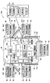
- FIG. 1 illustrates an overall configuration example of a vehicle control device 100 according to an embodiment of the present disclosure.
- the configuration related to the smart system is disclosed in detail in Japanese Patent No. 4581848 (corresponding to US Pat. No. 8,253,534). State.
- the vehicle control device 100 is based on the ID code verification result, the user's operation intention, and the vehicle state based on bidirectional communication between the portable device 1 possessed by the user and the vehicle side unit provided on the vehicle body side of the vehicle 10.
- an ECU 4 corresponding to an ID code determination unit, a condition determination unit, an output unit, a vehicle state acquisition unit, a position specifying unit, a selection unit, a verification unit, and an operation permission unit controls the operation of the opening / closing body (details will be described later).
- the portable device 1 includes a control unit 1c including a well-known CPU, ROM, RAM (all not shown) and the like, and a receiver 1a connected to the control unit 1c for receiving a polling signal from the vehicle side unit, Transmitter 1b for transmitting a response signal including an ID code to respond to this polling signal, operation unit 1d for user operation, program necessary for operation of portable device 1, and data such as ID code Including a memory 1e.
- the control unit 1c determines whether or not a polling signal has been received based on the received signal of the receiver 1a, generates a response signal including an ID code for verification to respond to the polling signal, 1b is transmitted.
- the operation unit 1d includes, for example, a push switch group serving as a trigger for using the remote keyless entry function. Depending on the operation state, for example, a command signal requesting to lock / unlock or open / close the doors 11 to 14 and unlock or open / close the rear door 15 is transmitted from the transmitter 1b.
- a tablet-type terminal typified by a well-known smartphone (a general term for a portable information terminal equipped with a touch panel on a display portion such as a liquid crystal display and operated with a finger), a mobile phone
- a portable communication terminal or a dedicated portable terminal that only transmits an ID code to a polling signal may be used.
- the ECU 4 includes vehicle interior transmitters 2a to 2e provided in the doors 11 to 15 (corresponding to a polling signal output unit), a vehicle interior transmitter 2f provided in the vehicle interior (corresponding to a polling signal output unit), a vehicle interior Is connected to a receiver 3 (corresponding to an operation intention acquisition unit, an ID code acquisition unit, and an ID code reception unit).
- the vehicle-side unit includes at least an ECU 4, a vehicle exterior transmitter (generally referred to as 2 a to 2 e, hereinafter the same), a vehicle interior transmitter 2 f, and a receiver 3.
- the ECU 4 includes door lock control units 5a to 5e provided on the doors 11 to 15, slide door drive units 7c and 7d, window drive units 11b to 14b, a door mirror drive unit 16, a vehicle state detection unit 18 (FIG. 1). Then, “detection unit” is connected so that data communication is possible.
- “detection unit” is connected so that data communication is possible.
- the connection form either an in-vehicle LAN or a direct line system for direct connection may be used.
- the ECU 4 is configured as a computer including a well-known CPU, ROM, RAM (all not shown), peripheral circuits, and the like.
- the CPU executes the control program stored in the ROM, thereby realizing various functions of the vehicle control device.
- the vehicle interior transmitter and vehicle interior transmitter 2f transmit a polling signal based on a transmission instruction signal from the ECU 4.
- the reach distance of the polling signal is set to about 0.7 to 1.0 m, for example.
- detection areas corresponding to the reach distance of the polling signal are formed around each of the doors 11 to 15, and it is possible to detect which door the holder of the portable device 1 has approached.
- the detection area by the vehicle interior transmitter 2f is set so as to cover the vehicle interior, and detects whether the portable device 1 is in the vehicle interior.
- the receiver 3 is ready to receive a response signal from the portable device 1 in synchronization with the output timing of the polling signal transmission instruction signal to the vehicle interior transmitter and vehicle interior transmitter 2f.
- the response signal received by the receiver 3 is output to the ECU 4.
- the ECU 4 collates the ID code included in the received response signal with the master code stored by itself, and based on the collation result, for example, whether to control the door locking / unlocking operation or not. Judgment is made.
- the above-described configuration is “a polling signal output unit (2a to 2e, 2f) that wirelessly outputs a polling signal for polling the portable device and an ID code transmitted from the portable device based on the reception of the polling signal”
- the ID code receiving unit also serves as the ID code acquiring unit
- the collating unit also serves as the ID code determining unit.
- a configuration that does not share a function with a smart system for example, a predetermined operation is permitted based on a collation result of an ID code
- a predetermined operation is permitted based on a collation result of an ID code
- the receiver 3 receives the operation intention information from the tire side device 30a (see FIG. 3). The received operation intention information is output to the ECU 4.
- the door lock control unit (generic name for 5a to 5e, hereinafter the same) locks or unlocks the doors 11 to 15 based on an instruction signal from the ECU 4, but the holder of the portable device 1 By touching the door handles 6a to 6e of the doors 11 to 15, an unlock standby state in which unlocking is possible is set.
- the door handle (general name of 6a to 6e, hereinafter the same) is provided with touch sensors (indicated as “sensor” in FIG. 1) 6a1 to 6e1, and the holder of the portable device 1 touches the door handle to determine a predetermined value. It is detected that the operation was performed.
- the door handle is also configured as a push switch, and is provided with door lock switches (indicated as “SW” in FIG. 1) 6a2 to 6e2 (as an example of a door lock device) for locking the doors 11 to 15. It is done. Further, the door handles 6a to 6e also operate as antennas of the vehicle interior transmitters 2a to 2e, respectively.
- the sliding door drive units 7c and 7d use a motor as a drive source, and slide type doors (hereinafter referred to as “sliding doors”) 13 and 14 corresponding to the rear seats of the vehicle 10, respectively, according to an open / close signal from the ECU 4. Open and close automatically.
- hinged doors 11 and 12 are provided corresponding to the front seats of the vehicle 10.
- the rear door drive unit 8 uses a motor as a drive source, and automatically opens and closes the flip-up type or side-open type rear door 15 according to an open / close signal from the ECU 4.
- the rear door 15 may be provided with a window and a window driving unit.
- the window driving unit (generic name for 11b to 14b, hereinafter the same) performs opening / closing driving of the windows 11a to 14a of the doors 11 to 14.
- the window driving unit can also perform opening / closing driving based on a control command from the ECU 4 in addition to opening / closing driving of the window based on operation of an operation switch (not shown).
- the door mirror drive unit 16 opens and closes the door mirrors 17a and 17b.
- the door mirror drive unit 16 can also perform opening / closing driving based on a control command from the ECU 4 in addition to opening / closing driving of the door mirrors (generically referred to as 17a and 17b, the same applies hereinafter) based on the operation of a user operation switch (not shown). .
- the door lock switches 6a2 to 6e2, the windows 11a to 14a, the slide doors 13 and 14, the rear door 15, and the door mirrors 17a and 17b correspond to an opening / closing body. With this configuration, it is possible to perform drive control of main opening / closing bodies provided in the vehicle by vibrating the tire.
- -Door lock switch The unlocked state (switch is closed) is the first state, and the locked state (switch is open) is the second state.
- -Window The closed state is the first state, and the open state is the second state.
- the opening of the window in the open state front open, half open, etc.
- -Slide door, rear door The closed state is the first state and the open state is the second state. Similar to the window, the opening degree of the door in the open state can be arbitrarily set.
- Door mirror The closed (retracted) state is the first state, and the open (deployed) state is the second state.
- the vehicle state detection unit 18 is a sensor or switch that detects the state of the vehicle, and includes at least one of the following.
- a shift position sensor that detects the position of a shift lever (not shown) of the vehicle 10.
- a vehicle speed sensor that detects the speed of the vehicle 10.
- a parking brake switch that detects the state of a parking brake (not shown) of the vehicle 10.
- a tachometer that detects the number of revolutions of a prime mover (not shown) including at least one of an engine and a motor.
- a start switch (for example, an ignition switch) that permits starting of the prime mover of the vehicle 10.
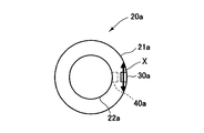
- the wheel 20a includes a tire 21a and a wheel 22a.
- a tire-side device 30a (corresponding to an operation intention detection unit) is provided on the inner side of the tire 21a, for example, near the center in the tire width direction of the tread back surface of the tire 21a (the surface that contacts the road surface).
- the tire side device 30a may be provided inside the wheel 22a as in 40a.
- the tire-side device 30 a includes a vibration detection element 31, a power supply circuit 32 or 33, a signal processing circuit 34, and a transmitter 35.
- the vibration detection element 31 detects, for example, vibration in a direction (tire tangent direction: direction of arrow X in FIG. 2) in contact with a circular orbit drawn by the tire-side device 30a when the tire 21a rotates. Any of the following may be used for the vibration detection element 31.
- Vibration power generation elements that convert vibration energy into electrical energy. Any of an electrostatic induction type power generation element, a piezoelectric element, or a friction type, magnetostriction type, or electromagnetic induction type power generation element may be used.
- strain gauges strain gauges, semiconductor acceleration sensors, differential transformers.
- the operation intention detection unit includes the vibration detection element (31)”.
- the user's intention to operate can be detected with a simple configuration.
- the power supply circuit 33 in the case of using a device that cannot supply the necessary power includes a known battery 33a and a power supply circuit 33b that converts the voltage of the battery 33a into an operating voltage of each part, for example.
- the signal is supplied to the signal processing circuit 34 and the transmitter 35 via the circuit 33b.
- the power supply circuit 32 in the case of using a vibration detection element or a vibration power generation element that does not require external power supply includes a rectification unit 32a and a power storage unit 32b, and converts the power generated by the vibration detection element 31 into a signal processing circuit. 34 and the transmitter 35. In this configuration, the tire side device 30a is operated by the electric power generated by the vibration.
- the rectification unit 32a converts AC power generated by the vibration detection element 31 into DC power and outputs the DC power to the power storage unit 32b, and may be a known full-wave rectification circuit or a half-wave rectification circuit.
- the power storage unit 32b is a circuit for storing the DC power output from the rectification unit 32a and includes, for example, a known capacitor.
- the power storage unit 32b stores the surplus when the vibration detection element 31 generates excessive power, and discharges to compensate for the shortage when the power generation amount is insufficient.
- the signal processing circuit 34 includes a known CPU, ROM, RAM, signal input / output circuit, and a bus connecting them.
- the signal processing circuit 34 includes a vibration section detection unit 34a, a time measurement unit 34b, a high frequency component extraction unit 34c, a determination unit 34d, and a storage unit 34e such as a flash memory as functions for performing signal processing.
- the signal processing circuit 34 determines from the vibration data acquired from the vibration detection element 31 whether or not the vibration is given to the wheel by the user (reflecting the intention of operation) while the vehicle 10 is parked. Output the result.
- the power supply circuit 32 or 33 separates the wakeup signal ( It may be a pulse signal or a rising or falling edge signal) and output to the signal processing circuit 34.
- the signal processing circuit 34 uses the wakeup signal as a trigger to make a transition (wakeup) from a power saving mode (also referred to as a sleep mode) that consumes less power than the normal operation mode to a normal operation mode.
- the mode shifts to the power saving mode. Or stop the operation. Thereby, the power consumption of the tire side device 30a can be reduced, and the burden on the power storage unit 32b or the battery 33a can be reduced.
- the vibration section detector 34a detects a section in which the output voltage of the vibration detection element 31 exceeds a predetermined value as a vibration section.
- the time measurement unit 34b measures the time of the vibration section detected by the vibration section detection unit 34a.
- the high frequency component extraction unit 34c extracts, for example, a high frequency component (high frequency vibration data) in a vibration section using a wavelet filter or a known high pass filter.
- the determination unit 34d determines the cause of vibration based on the time of the vibration section measured by the time measurement unit 34b and the high frequency component extracted by the high frequency component extraction unit 34c.
- the storage unit 34e stores a program and data for the determination unit 34d to determine the operation intention.
- the transmitter 35 transmits the operation intention information output by the determination unit 34d of the signal processing circuit 34 to the vehicle side unit.
- the communication between the transmitter 35 and the receiver 3 included in the vehicle-side unit uses, for example, a known short-range wireless communication technology such as Bluetooth (registered trademark).
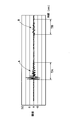
- FIG. 4 shows the output voltage of the vibration detecting element 31 measured by the inventor of the present disclosure when the user gives vibration to the wheel (for example, when the wheel is kicked) and when the door is closed.
- Vibration caused by force applied directly to the wheel such as when the user applies vibration to the wheel, and vibration caused by force applied to the wheel via the vehicle body, such as when the door is closed (waveform B)
- the amplitude, the time of the vibration section (TA, TB), and the high frequency component are different. From this difference, the presence or absence of the user's intention to board is determined.
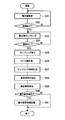
- the operation intention information output process executed in the normal operation mode in the signal processing circuit 34 will be described with reference to FIG.
- the voltage value output by the vibration detection element 31 is acquired (S31).
- it is determined whether or not there is vibration that is, whether or not the state where the voltage value exceeds the value when it is considered that there is no vibration has continued for a predetermined time.
- the voltage value changes S32: Yes
- the voltage value is sampled (S33). That is, the voltage value output by the vibration detection element 31 is acquired and stored in the storage unit 34e.
- S34 Yes
- the sampling of the voltage value is finished (S35).
- the peak value is measured by the vibration section detector 34a (S36)
- the sampling time is measured by the time measurement section 34b (S37)
- the high-frequency component extraction section is extracted (S38) by 34c.
- detection of the user's intention to operate that is, whether or not the vibration is caused by the user is determined (S39). For example, the time, amplitude, and high frequency components of the vibration section when the user applies vibration to the wheel are measured in advance and stored in the storage unit 34e as a reference value or a reference range. When the measured value matches the reference value or is included in the reference range, it is determined that the vibration is caused by the user.
- the threshold value is D (absolute value)
- the vibration section time is TA ⁇ ⁇ ( ⁇ : a value defining the reference range)
- the high-frequency component extracted from the waveform A is the reference value or reference range.
- the vehicle state detected by the vehicle state detection unit 18 is acquired (S11).
- the determination method uses at least one of the following.
- the shift position sensor of the vehicle 10 is in the parking position, it is determined that the vehicle 10 is in the parking state.
- the speed of the vehicle 10 is 0 km / h, it determines with the vehicle 10 being a parking state.
- the parking brake of the vehicle 10 is in the operating state, it is determined that the vehicle 10 is in the parking state.
- the above-described configuration is “provided with a vehicle state acquisition unit (4) for acquiring the vehicle state, and the condition determination unit makes a determination when the vehicle is in a predetermined state”. More specifically, “the condition determining unit determines when the vehicle is in a parked state”. With this configuration, it is possible to prevent the opening / closing body from operating against the user's intention due to the vibration of the running tire.
- the collation result is determined to be normal, and the position of the portable device 1 at this time is specified (S17). That is, it is checked which transmitter (outside the vehicle compartment or in the vehicle interior) the response signal when the normal verification is determined is a response to the polling signal.
- the above-described configuration is “provided with the position specifying unit (4) for specifying the position of the portable device, and the condition determining unit makes a determination when the portable device is not present in the vehicle interior”.
- the portable device When the portable device is present in the vehicle interior, it is considered that the user gets on and performs some operation. According to this configuration, it is possible to prevent the user from competing with the operation of the user.
- the position of the wheel that has detected the vibration is specified (S20). It is assumed that an output condition for outputting the operation command information is satisfied when the collation is normally performed and the operation intention information is received.
- the method for specifying the position of the wheel uses at least one of the following.
- the wheel that is closest to the position of the portable device 1 when the collation is normally performed is the wheel that has detected vibration. Unlike the configuration including the wheel identification information, the association between the wheel identification information and the wheel position is unnecessary.
- the position of the wheel is specified based on the wheel identification information. In this case, the wheel identification information and the wheel position are associated with each other and registered in advance in the ECU 4. When wheel rotation is performed, it is necessary to register again.
- the position of the wheel is specified from the intensity of the radio wave from the transmitter 35 received by the receiver 3.
- an object to be operated is selected from the above-described opening and closing bodies (S21). Any of the following is used as the selection method. Only a specific opening / closing body (for example, only the sliding doors 13 and 14) is set as an operation target. The wheel vibration pattern and the opening / closing body to be operated are associated with each other and stored in the memory of the ECU 4 in advance. Thereby, a plurality of opening / closing bodies can be operated simultaneously. Further, the driver side door can be vibrated to unlock the passenger seat door. The wheel position where the vibration is detected and the opening / closing body to be operated are associated with each other and stored in the memory of the ECU 4 in advance. For example, the door is locked / unlocked or opened / closed near the position of the wheel where the vibration is detected.
- These two configurations are “equipped with a selection unit (4) for selecting an opening / closing body that commands an operation based on a detection state of an operation intention”.
- the user can open and close a desired opening / closing body without performing an operation other than vibrating the tire.
- the position of the portable device 1 when the collation is normally performed and the opening / closing body to be operated are associated with each other and stored in the memory of the ECU 4 in advance.
- a plurality of opening / closing bodies can be operated simultaneously.
- This configuration includes “a position specifying unit (4) that specifies the position of the portable device and a selection unit (4) that selects an opening / closing body that commands operation based on the position of the portable device”. .
- the user can open and close a desired opening / closing body without performing an operation other than vibrating the tire.
- the operation command information is output to the drive unit of the opening / closing body that is the operation target (S22).
- the operation command information includes the fact that the first state and the second state are switched cyclically.
- the above-mentioned configuration is “the opening / closing body includes a first state and a second state different from the first state, and the operation command information includes cyclic switching between the first state and the second state” It is. With this configuration, it is possible to prevent the state management of the opening / closing body from becoming complicated.
- the state of each open / close body is acquired and stored in the memory of the ECU 4. If the state is the first state, the second state is set. The operation command information indicating the state is output.
- each open / close body is respectively connected to the respective open / close bodies.
- the drive units door lock control units 5a to 5e, window drive units 11b to 14b, slide door drive units 7c and 7d, rear door drive unit 8 and door mirror drive unit 16
- the first state may be switched to the second state, and the second state may be switched to the first state for driving.
Landscapes
- Engineering & Computer Science (AREA)
- Mechanical Engineering (AREA)
- Lock And Its Accessories (AREA)
Abstract
より低コストかつ簡易な構成で、手荷物等で両手が塞がっている状態でも、車両のドアなどの開閉体を開閉駆動させることができる車両用制御装置を提供する。車両用制御装置は、車両(10)のタイヤ(21a)またはホイール(22a)に設けられ、車両の開閉体に対する、ユーザの操作意思の有無を検知する操作意思検知部(30a)と、車両の車体に設けられ、操作意思を取得する操作意思取得部(3)と、ユーザの所持する携帯機(1)から、ユーザあるいは携帯機を識別するためのIDコードを取得するIDコード取得部(3)と、IDコードが正しいものか否かを判定するIDコード判定部(4)と、ユーザの操作意思およびIDコードの判定結果に基づいて、開閉体の動作を指令する動作指令情報を出力するための出力条件が成立したか否かを判定する条件判定部(4)と、出力条件が成立したときに、動作指令情報を出力する出力部(4)と、を備える。
Description
本出願は、2013年12月3日に出願された日本出願番号2013-249767号に基づくもので、ここにその記載内容を援用する。
本開示は、車両用制御装置に関する。
車両のユーザが車両ドアにユーザ自身の力を直接作用させずに車両ドアを開閉する装置が知られている。例えば、車両外面に配置したセンサユニットによってユーザの動きを非接触検出して車両ドアを動作させる車両用ドア開閉装置が考案されている(特許文献1参照)。
また、電子キーシステム(スマートシステム、キーレスエントリーシステムともいう)において、ユーザの所持する携帯機との照合が正しく行われたとき、かつ、車両の各タイヤの空気圧の変動が予め定められた変動パターンと一致したと判定されたときに、車両のドアのロックあるいはアンロックを許可する電子キーシステムが考案されている(特許文献2参照)。
特許文献1の構成では、所定範囲内の人体の有無を検出する接近センサおよび人体の手の振り方向を検出するモーションセンサを搭載する必要があるため、装置のコストが上昇してしまう。
特許文献2の構成では、人がタイヤに振動を与えたときの空気圧の変化は微小であることが知られており、高感度の空気圧センサを必要とするので、コストが上昇する。特に、タイヤ空気圧監視装置は、車両が走行時のタイヤ空気圧を監視することを主目的としている。さらに、空気圧センサを含むタイヤ側の装置は、電池により駆動する。このため、駐車時にも空気圧を監視すると、電池の消耗が早くなってしまう。
上記問題点を背景として、本開示は、より低コストかつ簡易な構成で、手荷物等で両手が塞がっている状態でも、車両のドアなどの開閉体を開閉駆動させることができる車両用制御装置を提供することを目的とする。
本開示の一態様によれば、車両用制御装置は、車両のタイヤまたはホイールに設けられ、車両に備えられ予め定められた開閉動作を行う開閉体に対する、ユーザの操作意思の有無を検知する操作意思検知部と、車両の車体に設けられ、操作意思を取得する操作意思取得部と、ユーザの所持する携帯機から、ユーザあるいは携帯機を識別するためのIDコードを取得するIDコード取得部と、IDコードが正しいものか否かを判定するIDコード判定部と、ユーザの操作意思およびIDコードの判定結果に基づいて、開閉体の動作を指令する動作指令情報を出力するための出力条件が成立したか否かを判定する条件判定部と、出力条件が成立したときに、動作指令情報を出力する出力部と、を備える。
上記構成によって、モーションセンサを搭載する必要はなく、比較的低コストで本開示の構成を実現できる。また、高感度の空気圧センサも不要である。
本開示についての上記目的およびその他の目的、特徴や利点は、添付の図面を参照しながら下記の詳細な記述により、より明確になる。図面において、
本開示の一実施形態にかかる車両用制御装置の構成を示す図。
車輪の構成を示す図。
車両用制御装置のタイヤ側装置の構成を示す図。
振動判定を説明する図。
車両用制御装置の操作意思情報出力処理を説明するフロー図。
車両用制御装置の動作指令情報出力処理を説明するフロー図。
図1に、本開示の一実施形態にかかる車両用制御装置100の全体構成例を示す。なお、本構成のうち、スマートシステムに関する構成は、日本特許第4561848号公報(米国特許第8253534号公報に対応)に詳細が開示されているので、参照による引用を行うことにより、ここでは概略を述べる。
車両用制御装置100は、ユーザが所持する携帯機1と、車両10の車体側に備えられた車両側ユニットとの双方向通信によるIDコードの照合結果、ユーザの操作意思、および車両状態を基に、ECU4(IDコード判定部、条件判定部、出力部、車両状態取得部、位置特定部、選択部、照合部、動作許可部に相当)が開閉体(詳細は後述)の動作を制御する。
携帯機1は、周知のCPU、ROM、RAM(いずれも図示せず)等を含む制御部1c、および、制御部1cに接続された、車両側ユニットからのポーリング信号を受信する受信機1a、このポーリング信号に応答するための、IDコード等を含むレスポンス信号を送信する送信機1b、ユーザが操作を行なうための操作部1d、携帯機1の動作に必要なプログラム、およびIDコード等のデータを記憶するメモリ1eを含む。
制御部1cは、受信機1aの受信信号に基づいてポーリング信号の受信の有無を判定し、ポーリング信号に応答するための、照合のためのIDコード等を含むレスポンス信号を生成して、送信機1bから送信させる。
操作部1dは、例えば、リモートキーレスエントリー機能を利用するためのトリガとなるプッシュスイッチ群を含む。操作状態に応じて、例えば、ドア11~14のロック/アンロックあるいは開閉、後部ドア15のアンロックあるいは開閉を行うことを要求するコマンド信号を送信機1bから送信する。
携帯機1として、上述したスマートキーの他に、周知のスマートフォンに代表されるタブレット型端末(液晶ディスプレイなどの表示部分にタッチパネルを搭載し、指で操作する携帯情報端末の総称)、携帯電話機のような携帯通信端末、あるいは、ポーリング信号に対してIDコードの送信のみを行う専用の携帯端末を用いてもよい。
ECU4には、ドア11~15に設けられた車室外送信機2a~2e(ポーリング信号出力部に相当)、車室内に設けられた車室内送信機2f(ポーリング信号出力部に相当)、車室内に設けられた受信機3(操作意思取得部、IDコード取得部、IDコード受信部に相当)、が接続される。車両側ユニットは、少なくとも、ECU4、車室外送信機(2a~2eの総称、以下同じ)、および車室内送信機2f、受信機3を含む。
また、ECU4には、ドア11~15に設けられたドアロック制御部5a~5e、スライドドア駆動部7c、7d、窓駆動部11b~14b、ドアミラー駆動部16、車両状態検出部18(図1では、「検出部」と表記)が、データ通信可能に接続される。接続形態は、車内LANあるいは直接接続するじか線方式のいずれを用いてもよい。
ECU4は、周知のCPU、ROM、RAM(いずれも図示せず)、および周辺回路等を含むコンピュータとして構成される。例えば、ROMに記憶された制御プログラムを、CPUが実行することで、車両用制御装置の種々の機能を実現する。
車室外送信機および車室内送信機2fは、ECU4からの送信指示信号に基づいてポーリング信号を送信する。ポーリング信号の到達距離は、例えば0.7~1.0m程度に設定する。車両10の駐車時には、そのポーリング信号の到達距離に応じた検知エリアがドア11~15のそれぞれの周囲に形成され、携帯機1の保持者がいずれのドアに接近したかを検知できる。また、車室内送信機2fによる検知エリアは、車室内をカバーするように設定し、携帯機1が車室内にあるか否かを検知する。
受信機3は、車室外送信機および車室内送信機2fに対する、ポーリング信号の送信指示信号の出力タイミングと同期して、携帯機1からのレスポンス信号を受信可能な状態となる。受信機3が受信したレスポンス信号は、ECU4に出力する。ECU4は、この受信したレスポンス信号に含まれるIDコードと、自身が記憶するマスタコードとの照合を行い、照合結果に基づいて、例えば、ドアのロック/アンロック動作の制御等を実行すべきか否か等の判定を行う。
上述の構成が、「携帯機をポーリングするためのポーリング信号を無線出力するポーリング信号出力部(2a~2e、2f)と、ポーリング信号の受信に基づいて携帯機から送信されるIDコードを受信するIDコード受信部(3)と、受信したIDコードと自身に記憶されたマスタコードとを照合する照合部(4)と、照合の結果に基づいて予め定められた動作を許可する動作許可部(4)と、を備えるスマートシステムにおいて、IDコード受信部がIDコード取得部を兼ね、照合部がIDコード判定部を兼ねる」ものである。本構成によって、スマートシステムの機能を共用することで、本開示の構成をより低コストで実現できる。
無論、スマートシステムと機能(例えば、IDコードの照合結果に基づいて予め定められた動作を許可する)を共用しない構成でもよい。こうすることで、スマートシステムを備えない車両においても、本開示の機能を実現できる。
受信機3は、タイヤ側装置30a(図3参照)から、操作意思情報を受信する。受信した操作意思情報は、ECU4に出力する。
ドアロック制御部(5a~5eの総称、以下同じ)は、ECU4からの指示信号に基づき、ドア11~15をロック/アンロック状態にしたり、ロックされているが、携帯機1の保持者がドア11~15のドアハンドル6a~6eに触れることによってアンロック可能なアンロックスタンバイ状態にする。
ドアハンドル(6a~6eの総称、以下同じ)には、タッチセンサ(図1では、「センサ」と表記)6a1~6e1が設けられ、携帯機1の保持者が、ドアハンドルに触れて、所定の操作を行ったことを検出する。また、ドアハンドルには、プッシュスイッチとして構成され、ドア11~15をロックするための、ドアロックスイッチ(図1では、「SW」と表記)6a2~6e2(ドアロック装置の一例として)も設けられる。また、ドアハンドル6a~6eは、それぞれ、車室外送信機2a~2eのアンテナとしても動作する。
スライドドア駆動部7c、7dは、モータを駆動源とし、ECU4からの開閉信号にしたがい、それぞれ、車両10の後席に対応したスライド式のドア(以降、「スライドドア」と称する)13、14を自動開閉する。また、車両10の前席に対応してヒンジ式のドア11、12を備える。
後部ドア駆動部8は、モータを駆動源とし、ECU4からの開閉信号にしたがい、跳ね上げ式あるいは横開き式の後部ドア15を自動開閉する。後部ドア15に窓および窓駆動部を設けてもよい。
窓駆動部(11b~14bの総称、以下同じ)は、ドア11~14の窓11a~14aの開閉駆動を行う。窓駆動部は、操作スイッチ(図示せず)の操作に基づく窓の開閉駆動に加え、ECU4からの制御指令に基づく開閉駆動も行うこともできる。
ドアミラー駆動部16は、ドアミラー17a、17bの開閉駆動を行う。ドアミラー駆動部16は、ユーザの操作スイッチ(図示せず)の操作に基づくドアミラー(17a、17bの総称、以下同じ)の開閉駆動に加え、ECU4からの制御指令に基づく開閉駆動も行うこともできる。
ドアロックスイッチ6a2~6e2、窓11a~14a、スライドドア13、14、後部ドア15、ドアミラー17a、17bが開閉体に相当する。本構成によって、タイヤを振動させることで、車両に備えられた主な開閉体の駆動制御を行うことができる。
これら開閉体は、以下のように第一状態および第二状態を定める(符号は略)。
・ドアロックスイッチ:アンロック状態(スイッチが閉状態)を第一状態、ロック状態(スイッチが開状態)を第二状態とする。
・窓:閉状態を第一状態、開状態を第二状態とする。開状態のときの窓の開度(前開、半開など)は、任意に設定することができる。
・スライドドア、後部ドア:閉状態を第一状態、開状態を第二状態とする。窓と同様に、開状態のときのドアの開度は、任意に設定することができる。
・ドアミラー:閉(格納)状態を第一状態、開(展開)状態を第二状態とする。
・ドアロックスイッチ:アンロック状態(スイッチが閉状態)を第一状態、ロック状態(スイッチが開状態)を第二状態とする。
・窓:閉状態を第一状態、開状態を第二状態とする。開状態のときの窓の開度(前開、半開など)は、任意に設定することができる。
・スライドドア、後部ドア:閉状態を第一状態、開状態を第二状態とする。窓と同様に、開状態のときのドアの開度は、任意に設定することができる。
・ドアミラー:閉(格納)状態を第一状態、開(展開)状態を第二状態とする。
車両状態検出部18は、車両の状態を検出するセンサあるいはスイッチで、以下のうちの少なくとも一つを含む。
・車両10のシフトレバー(図示せず)の位置を検出するシフトポジションセンサ。
・車両10の速度を検出する車速センサ。
・車両10のパーキングブレーキ(図示せず)の状態を検出するパーキングブレーキスイッチ。
・車両10の原動機(エンジンおよびモータのうちの少なくとも一方を含む、図示せず)の回転数を検出する回転計。
・車両10の原動機の始動を許可する始動スイッチ(例えば、イグニッションスイッチ)。
・車両10のシフトレバー(図示せず)の位置を検出するシフトポジションセンサ。
・車両10の速度を検出する車速センサ。
・車両10のパーキングブレーキ(図示せず)の状態を検出するパーキングブレーキスイッチ。
・車両10の原動機(エンジンおよびモータのうちの少なくとも一方を含む、図示せず)の回転数を検出する回転計。
・車両10の原動機の始動を許可する始動スイッチ(例えば、イグニッションスイッチ)。
図2を用いて、車輪20aを例に挙げて、車輪(20a~20dの総称、以下同じ)の構成を説明する。車輪20aは、タイヤ21aとホイール22aを含む。タイヤ21aの内側、例えば、タイヤ21aのトレッド裏面(路面と接触する面を表面とする)の、タイヤ幅方向の中心近傍に、タイヤ側装置30a(操作意思検知部に相当)を備える。タイヤ側装置30aは、40aのようにホイール22aの内側に備えてもよい。
図3のように、タイヤ側装置30aは、振動検知素子31、電力供給回路32または33、信号処理回路34、送信機35を含む。
振動検知素子31は、例えば、タイヤ21aが回転する際にタイヤ側装置30aが描く円軌道に接する方向(タイヤ接線方向:図2中の矢印Xの方向)の振動を検知する。振動検知素子31は、以下のうちのいずれを用いてもよい。
・外部からの電源の供給を必要としないもの:振動エネルギーを電気エネルギーに変換する振動発電素子。静電誘導型の発電素子、圧電素子、あるいは摩擦式、磁歪式、電磁誘導型の発電素子のいずれを用いてもよい。
・外部からの電源の供給を必要とするもの:ひずみゲージあるいは半導体式の加速度センサ、差動トランス。
・外部からの電源の供給を必要としないもの:振動エネルギーを電気エネルギーに変換する振動発電素子。静電誘導型の発電素子、圧電素子、あるいは摩擦式、磁歪式、電磁誘導型の発電素子のいずれを用いてもよい。
・外部からの電源の供給を必要とするもの:ひずみゲージあるいは半導体式の加速度センサ、差動トランス。
上述の構成が、「操作意思検知部は、振動検知素子(31)を含む」ものである。本構成によって、簡易な構成でユーザの操作意思を検知できる。
外部からの電源の供給を必要とする振動検知素子(例えば、素子の他に増幅器等の周辺回路を含むもの)、あるいは振動発電素子のうち、該素子による発電電力ではタイヤ側装置30aの動作に必要な電力を供給できないものを用いる場合の電力供給回路33は、周知の電池33a、および、例えば電池33aの電圧を各部の作動電圧に変換する電源回路33bを含み、電池33aの電力を、電源回路33bを介して信号処理回路34および送信機35に供給する。
外部からの電源の供給を必要としない振動検知素子あるいは振動発電素子を用いる場合の電力供給回路32は、整流部32aおよび蓄電部32bを含み、振動検知素子31で発電した電力を、信号処理回路34および送信機35に供給する。本構成では、振動によって生じた電力によりタイヤ側装置30aが動作する。
整流部32aは、振動検知素子31が発電した交流電力を直流電力に変換し、蓄電部32bに出力するもので、公知の全波整流回路でも半波整流回路でもよい。蓄電部32bは、整流部32aが出力した直流電力を蓄電するための回路で、例えば周知のキャパシタを含む。蓄電部32bは、振動検知素子31が余剰に発電しているときはその余剰分を蓄電し、発電量が不足しているときは放電して不足分を補う。
信号処理回路34は、周知のCPU、ROM、RAM、信号入出力回路、およびこれらを接続するバスを備える。信号処理回路34は、信号処理を実施するための機能として、振動区間検出部34a、時間計測部34b、高周波成分抽出部34c、判定部34d、およびフラッシュメモリ等の記憶部34eを含む。信号処理回路34は、振動検知素子31より取得する振動データから、その振動が、車両10の駐車中に、ユーザが車輪に与えた(操作意思を反映した)ものか否かを判定し、その結果を出力する。
電力供給回路32または33は、振動検知素子31の出力電圧が、所定値(後述の振動検知判定に用いる値よりも小さくてもよい)を超えたとき、電圧値とは別に、ウエイクアップ信号(パルス信号でも立上りあるいは立下りのエッジ信号でもよい)として信号処理回路34に出力する。信号処理回路34は、ウエイクアップ信号をトリガとして、通常の動作モードよりも消費電力の低い省電力モード(スリープモードともいう)から通常の動作モードに遷移(ウエイクアップ)する。一方、例えば、振動検知素子31の出力電圧が上述の所定値を下回る状態が所定時間継続し、かつ、信号処理回路34で何らの処理を実行していないときは、省電力モードに遷移する、もしくは、動作を停止する。これによって、タイヤ側装置30aの消費電力を低減し、蓄電部32bあるいは電池33aの負担を低減できる。
振動区間検出部34aは、振動検知素子31の出力電圧が、予め定められた値を超えた区間を振動区間として検出する。時間計測部34bは、振動区間検出部34aが検出した振動区間の時間を計測する。高周波成分抽出部34cは、例えば、ウェーブレットフィルタ、あるいは公知のハイパスフィルタを用い、振動区間の高周波成分(高周波振動データ)を抽出する。判定部34dは、時間計測部34bで計測した振動区間の時間、および高周波成分抽出部34cで抽出した高周波成分に基づき、振動の原因を判定し、ユーザの操作意思によるものであれば操作意思情報として送信機35に出力する。記憶部34eは、判定部34dが操作意思を判定するためのプログラムおよびデータを記憶する。
送信機35は、信号処理回路34の判定部34dが出力した操作意思情報を車両側ユニットへ送信する。送信機35と車両側ユニットが備える受信機3との間の通信は、例えば、Bluetooth(登録商標)などの公知の近距離無線通信技術を用いる。
図4に、本願開示の発明者が測定した、ユーザが車輪に振動を与えたとき(例えば、車輪を蹴ったとき)、と、ドアを閉めたときの、振動検知素子31の出力電圧を示す。ユーザが車輪に振動を与えたときのような、直接車輪に加えられる力による振動(波形A)と、ドアを閉めたときのような、車体を介して車輪に加えられる力による振動(波形B)とでは、振幅、振動区間の時間(TA、TB)、および高周波成分は異なることが分かる。この相違から、ユーザの乗車意思の有無を判定する。
図5を用いて、信号処理回路34において、通常の動作モードで実行される操作意思情報出力処理を説明する。まず、振動検知素子31が出力する電圧値を取得する(S31)。次に、振動があるか否か、すなわち、電圧値が、振動がない考えられるときの値を超えた状態が所定時間継続したか否かを判定する。電圧値が変化したとき(S32:Yes)、電圧値のサンプリングを行う(S33)。すなわち、振動検知素子31が出力する電圧値を取得して記憶部34eに記憶する。そして、振動がないとき、すなわち、電圧値が、振動がない考えられるときの値に戻ったとき(S34:Yes、電圧値のサンプリングを終了する(S35)。
次に、サンプリング結果(すなわち、振動データ)から、振動区間検出部34aによるピーク値の計測(S36)、時間計測部34bによるサンプリング時間(振動区間の時間)の計測(S37)、高周波成分抽出部34cによる高周波成分の抽出(S38)を行う。
次に、ユーザの操作意思の検知、すなわち振動がユーザによるものか否かの判定を行う(S39)。例えば、ユーザが車輪に振動を与えたときの振動区間の時間、振幅および高周波成分を予め計測し、基準値あるいは基準範囲として記憶部34eに記憶しておく。そして、計測値が基準値に一致あるいは基準範囲に含まれるとき、ユーザによる振動と判定する。
図4では、閾値をD(絶対値)、振動区間の時間をTA±α(α:基準範囲を規定する値)、および波形Aから抽出した高周波成分を基準値あるいは基準範囲とする。
図5に戻り、ユーザの操作意思を検知しないとき(S40:No)本処理を終了する。一方、ユーザの操作意思を検知したとき(S40:Yes)、操作意思情報を生成して送信機35から送信する(S41)。記憶部34eに車輪を識別する車輪識別情報が記憶されているとき、車輪識別情報を操作意思情報に含めて送信してもよい。
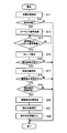
図6を用いて、ECU4で、所定のタイミングで繰り返し実行される動作指令情報出力処理を説明する。まず、車両状態検出部18が検出した車両状態を取得する(S11)。次に、車両状態に基づき、車両10が駐車状態か否かを判定する。判定方法は、以下のうちの少なくとも一つを用いる。
・車両10のシフトポジションセンサがパーキングの位置にあるとき、車両10が駐車状態であると判定。
・車両10の速度が0km/hのとき、車両10が駐車状態であると判定。
・車両10のパーキングブレーキが作動状態にあるとき、車両10が駐車状態であると判定。
・車両10の原動機の回転数が0rpmのとき、車両10が駐車状態であると判定。
・車両10の始動スイッチがオフ状態のとき、車両10が駐車状態であると判定。
・車両10のシフトポジションセンサがパーキングの位置にあるとき、車両10が駐車状態であると判定。
・車両10の速度が0km/hのとき、車両10が駐車状態であると判定。
・車両10のパーキングブレーキが作動状態にあるとき、車両10が駐車状態であると判定。
・車両10の原動機の回転数が0rpmのとき、車両10が駐車状態であると判定。
・車両10の始動スイッチがオフ状態のとき、車両10が駐車状態であると判定。
上述の構成が、「車両の状態を取得する車両状態取得部(4)を備え、車両が予め定められた状態にあるとき、条件判定部が判定を行う」ものである。より具体的には、「条件判定部は、車両が駐車状態にあるとき、条件判定部が判定を行う」ものである。本構成によって、走行中のタイヤの振動で、開閉体が、ユーザの意思に反して動作することを防止できる。
車両10が駐車状態でないとき(S12:No)、本処理を終了する。一方、車両10が駐車状態であるとき(S12:Yes)、車室外送信機および車室内送信機2fに送信指示信号を送って、ポーリング信号を送信させる(S13)。
ポーリング信号に対する携帯機1からのレスポンス信号を受信したとき(S14:Yes)、受信したレスポンス信号に含まれるIDコードを、自身が記憶するマスタコードと照合する(S15)。IDコードとマスタコードとが一致しないとき(S16:No)、本処理を終了する。
一方、IDコードとマスタコードとが一致したとき、(S16:Yes)、照合結果は正常と判定し、このときの携帯機1の位置を特定する(S17)。すなわち、正常照合と判定したときのレスポンス信号が、どの送信機(車室外あるいは車室内)からのポーリング信号に応答したものかを調べる。
携帯機1が車室内に存在するとき(S18:No)、本処理を終了する。一方、携帯機1が車室外に存在するとき(S18:Yes)、車輪から操作意思情報を受信したか否かを判定する。操作意思情報を受信しないとき(S19:No)、本処理を終了する。
上述の構成が、「携帯機の位置を特定する位置特定部(4)を備え、携帯機が車両の室内に存在しないとき、条件判定部が判定を行う」ものである。携帯機が車両の室内に存在するときは、ユーザが乗車して何らかの操作を行っていると考えられる。本構成によって、乗車しているユーザの操作と競合することを防止できる。
操作意思情報を受信したとき(S19:Yes)、振動を検知した車輪の位置を特定する(S20)。なお、照合が正常に行われ、かつ、操作意思情報を受信したとき、動作指令情報を出力するための出力条件が成立したとする。車輪の位置の特定方法は、以下のうちの少なくとも一つを用いる。
・照合が正常に行われたときの携帯機1の位置に最も近い車輪を、振動を検知した車輪とする。車輪識別情報を含む構成と異なり、車輪識別情報と車輪の位置との関連付けは不要である。
・操作意思情報に車輪識別情報を含むとき、車輪識別情報に基づいて車輪の位置を特定する。この場合、車輪識別情報と車輪の位置とを関連付けて、ECU4に予め登録しておく。車輪のローテーションを行ったときは、再度登録する必要がある。
・受信機3で受信した送信機35からの電波の強度から、車輪の位置を特定する。
・照合が正常に行われたときの携帯機1の位置に最も近い車輪を、振動を検知した車輪とする。車輪識別情報を含む構成と異なり、車輪識別情報と車輪の位置との関連付けは不要である。
・操作意思情報に車輪識別情報を含むとき、車輪識別情報に基づいて車輪の位置を特定する。この場合、車輪識別情報と車輪の位置とを関連付けて、ECU4に予め登録しておく。車輪のローテーションを行ったときは、再度登録する必要がある。
・受信機3で受信した送信機35からの電波の強度から、車輪の位置を特定する。
次に、上述の開閉体から動作対象とするものを選択する(S21)。選択方法は、以下のうちのいずれかを用いる。
・特定の開閉体のみ(例えば、スライドドア13、14のみ)を動作対象とする。
・車輪の振動パターンと、動作対象とする開閉体とを関連付けて、予めECU4のメモリに記憶しておく。これにより、複数の開閉体を同時に動作させることもできる。また、運転席側の車輪を振動させて、助手席のドアのアンロックを行うことができる。
・振動を検知した車輪の位置と、動作対象とする開閉体とを関連付けて、予めECU4のメモリに記憶しておく。例えば、振動を検知した車輪の位置に近いドアのロック/アンロックあるいは開閉を行う。
・特定の開閉体のみ(例えば、スライドドア13、14のみ)を動作対象とする。
・車輪の振動パターンと、動作対象とする開閉体とを関連付けて、予めECU4のメモリに記憶しておく。これにより、複数の開閉体を同時に動作させることもできる。また、運転席側の車輪を振動させて、助手席のドアのアンロックを行うことができる。
・振動を検知した車輪の位置と、動作対象とする開閉体とを関連付けて、予めECU4のメモリに記憶しておく。例えば、振動を検知した車輪の位置に近いドアのロック/アンロックあるいは開閉を行う。
これら2つの構成が、「操作意思の検知状態に基づいて、動作を指令する開閉体を選択する選択部(4)を備える」ものである。本構成によって、ユーザは、タイヤを振動させる以外の操作を行うことなく、所望の開閉体の開閉を行うことができる。
・照合が正常に行われたときの携帯機1の位置と、動作対象とする開閉体とを関連付けて、予めECU4のメモリに記憶しておく。複数の開閉体を同時に動作させることもできる。本構成が、「携帯機の位置を特定する位置特定部(4)と、携帯機の位置に基づいて、動作を指令する開閉体を選択する選択部(4)と、を備える」ものである。本構成によっても、ユーザは、タイヤを振動させる以外の操作を行うことなく、所望の開閉体の開閉を行うことができる。
・照合が正常に行われたときの携帯機1の位置と、動作対象とする開閉体とを関連付けて、予めECU4のメモリに記憶しておく。複数の開閉体を同時に動作させることもできる。本構成が、「携帯機の位置を特定する位置特定部(4)と、携帯機の位置に基づいて、動作を指令する開閉体を選択する選択部(4)と、を備える」ものである。本構成によっても、ユーザは、タイヤを振動させる以外の操作を行うことなく、所望の開閉体の開閉を行うことができる。
最後に、動作対象とした開閉体の駆動部に動作指令情報を出力する(S22)。動作指令情報は、第一状態および第二状態をサイクリックに切り換える旨を含む。
上述の構成が、「開閉体は、第一状態および第一状態とは異なる第二状態が予め定められ、動作指令情報は、第一状態および第二状態をサイクリックに切り換える旨を含む」ものである。本構成によって、開閉体の状態管理が複雑になることを防止できる。
例えば、予め定められたタイミングで、各開閉体の状態を取得してECU4のメモリに記憶し、その状態が第一状態であれば第二状態とする旨の、第二状態であれば第一状態とする旨の動作指令情報を出力する。
また、各開閉体の駆動部(ドアロック制御部5a~5e、窓駆動部11b~14b、スライドドア駆動部7c、7d、後部ドア駆動部8、ドアミラー駆動部16)が、それぞれ各開閉体の状態を管理し、動作指令情報を取得したときに、第一状態であれば第二状態に、第二状態であれば第一状態に切り換え駆動するようにしてもよい。
以上、本開示の実施の形態を説明したが、これらはあくまで例示にすぎず、本開示はこれらに限定されるものではなく、本開示の趣旨を逸脱しない限りにおいて、当業者の知識に基づく種々の変更が可能である。
Claims (10)
- 車両(10)のタイヤ(21a)またはホイール(22a)に設けられ、前記車両に備えられ予め定められた開閉動作を行う開閉体に対する、ユーザの操作意思の有無を検知する操作意思検知部(30a)と、
前記車両の車体に設けられ、
前記操作意思を取得する操作意思取得部(3)と、
前記ユーザの所持する携帯機(1)から、前記ユーザあるいは前記携帯機を識別するためのIDコードを取得するIDコード取得部(3)と、
前記IDコードが正しいものか否かを判定するIDコード判定部(4)と、
前記ユーザの操作意思および前記IDコードの判定結果に基づいて、前記開閉体の動作を指令する動作指令情報を出力するための出力条件が成立したか否かを判定する条件判定部(4)と、
前記出力条件が成立したときに、前記動作指令情報を出力する出力部(4)と、
を備える車両用制御装置。 - 前記操作意思検知部は、振動検知素子(31)を含む請求項1に記載の車両用制御装置。
- 前記車両の状態を取得する車両状態取得部(4)を備え、
前記車両が予め定められた状態にあるとき、前記条件判定部が判定を行う請求項1または請求項2に記載の車両用制御装置。 - 前記車両が駐車状態にあるとき、前記条件判定部が判定を行う請求項3に記載の車両用制御装置。
- 前記携帯機の位置を特定する位置特定部(4)を備え、
前記携帯機が前記車両の室内に存在しないとき、前記条件判定部が判定を行う請求項3または請求項4に記載の車両用制御装置。 - 前記操作意思の検知状態に基づいて、動作を指令する開閉体を選択する選択部(4)を備える請求項1ないし請求項5のいずれか1項に記載の車両用制御装置。
- 前記携帯機の位置を特定する位置特定部(4)と、
前記携帯機の位置に基づいて、動作を指令する開閉体を選択する選択部(4)と、
を備える請求項1ないし請求項6のいずれか1項に記載の車両用制御装置。 - 前記開閉体は、第一状態および前記第一状態とは異なる第二状態が予め定められ、
前記動作指令情報は、前記第一状態および前記第二状態をサイクリックに切り換える旨を含む請求項1ないし請求項7のいずれか1項に記載の車両用制御装置。 - 前記携帯機をポーリングするためのポーリング信号を無線出力するポーリング信号出力部(2a~2e、2f)と、
前記ポーリング信号の受信に基づいて前記携帯機から送信されるIDコードを受信するIDコード受信部(3)と、
受信した前記IDコードと自身に記憶されたマスタコードとを照合する照合部(4)と、
前記照合の結果に基づいて予め定められた動作を許可する動作許可部(4)と、
を備えるスマートシステムにおいて、
前記IDコード受信部が前記IDコード取得部を兼ね、前記照合部が前記IDコード判定部を兼ねる請求項1ないし請求項8のいずれか1項に記載の車両用制御装置。 - 前記開閉体は、ドア(11~15)、ドアロック装置(6a2~6e2)、窓(11a~14a)、ドアミラー(17a、17b)のうちの少なくとも一つを含む請求項1ないし請求項9のいずれか1項に記載の車両用制御装置。
Priority Applications (1)
| Application Number | Priority Date | Filing Date | Title |
|---|---|---|---|
| US15/100,466 US9764714B2 (en) | 2013-12-03 | 2014-11-19 | Vehicular control device |
Applications Claiming Priority (2)
| Application Number | Priority Date | Filing Date | Title |
|---|---|---|---|
| JP2013-249767 | 2013-12-03 | ||
| JP2013249767A JP6235885B2 (ja) | 2013-12-03 | 2013-12-03 | 車両用制御装置 |
Publications (1)
| Publication Number | Publication Date |
|---|---|
| WO2015083335A1 true WO2015083335A1 (ja) | 2015-06-11 |
Family
ID=53273120
Family Applications (1)
| Application Number | Title | Priority Date | Filing Date |
|---|---|---|---|
| PCT/JP2014/005798 Ceased WO2015083335A1 (ja) | 2013-12-03 | 2014-11-19 | 車両用制御装置 |
Country Status (3)
| Country | Link |
|---|---|
| US (1) | US9764714B2 (ja) |
| JP (1) | JP6235885B2 (ja) |
| WO (1) | WO2015083335A1 (ja) |
Families Citing this family (5)
| Publication number | Priority date | Publication date | Assignee | Title |
|---|---|---|---|---|
| US10384519B1 (en) * | 2016-01-12 | 2019-08-20 | Apple Inc. | Doors with adaptive positioning |
| JP6631552B2 (ja) * | 2017-02-07 | 2020-01-15 | トヨタ自動車株式会社 | 車両制御システム |
| US10124768B1 (en) * | 2017-05-09 | 2018-11-13 | Robert Bosch Gmbh | Bluetooth low energy (BLE) passive vehicle access control system for defending the system against relay attacks and method thereof |
| CN111192378B (zh) * | 2018-11-15 | 2022-01-28 | 中兴通讯股份有限公司 | 一种车辆移动识别方法、装置及车辆告警系统 |
| KR102652461B1 (ko) * | 2021-12-24 | 2024-03-28 | 주식회사 유라코퍼레이션 | 차량의 도어락 해제 시스템 및 그 방법 |
Citations (6)
| Publication number | Priority date | Publication date | Assignee | Title |
|---|---|---|---|---|
| JP2001234653A (ja) * | 1999-11-09 | 2001-08-31 | Mazda Motor Corp | 車両の開閉体制御装置 |
| JP2004132042A (ja) * | 2002-10-10 | 2004-04-30 | Fuji Heavy Ind Ltd | キーレスエントリーシステム |
| JP2004316231A (ja) * | 2003-04-16 | 2004-11-11 | Nissan Motor Co Ltd | 自動ドアオープナーシステム |
| JP2010133099A (ja) * | 2008-12-03 | 2010-06-17 | Panasonic Corp | 無線装置、その制御方法、およびプログラム |
| JP2012017558A (ja) * | 2010-07-06 | 2012-01-26 | Denso Corp | 制御システム |
| JP2013167150A (ja) * | 2013-03-18 | 2013-08-29 | Tokai Rika Co Ltd | 施解錠操作検出装置 |
Family Cites Families (10)
| Publication number | Priority date | Publication date | Assignee | Title |
|---|---|---|---|---|
| JP4439985B2 (ja) | 2004-04-20 | 2010-03-24 | 株式会社ブリヂストン | 路面摩擦係数の推定方法、路面摩擦係数推定装置、及び、車両制御装置 |
| US8131420B2 (en) * | 2008-02-27 | 2012-03-06 | Simmonds Precision Products, Inc. | Vehicle health and usage monitoring system and method |
| JP4561848B2 (ja) | 2008-03-06 | 2010-10-13 | 株式会社デンソー | 車両ドア制御システム |
| JP5131544B2 (ja) * | 2008-06-26 | 2013-01-30 | アイシン精機株式会社 | 車両用ドアシステム制御装置 |
| JP5265440B2 (ja) | 2009-04-06 | 2013-08-14 | 矢崎エナジーシステム株式会社 | 積載重量推定装置 |
| JP2012025253A (ja) * | 2010-07-22 | 2012-02-09 | Denso Corp | 車両用制御システム |
| JP2012112196A (ja) | 2010-11-26 | 2012-06-14 | Denso Corp | 電子キーシステム |
| JP2013028903A (ja) | 2011-07-27 | 2013-02-07 | Aisin Seiki Co Ltd | 車両用ドア開閉装置 |
| KR20130066348A (ko) * | 2011-12-12 | 2013-06-20 | 현대자동차주식회사 | 차량의 핸즈프리 시스템 제어방법 |
| US9827815B2 (en) | 2013-03-15 | 2017-11-28 | Denso Corporation | Tire device |
-
2013
- 2013-12-03 JP JP2013249767A patent/JP6235885B2/ja not_active Expired - Fee Related
-
2014
- 2014-11-19 US US15/100,466 patent/US9764714B2/en not_active Expired - Fee Related
- 2014-11-19 WO PCT/JP2014/005798 patent/WO2015083335A1/ja not_active Ceased
Patent Citations (6)
| Publication number | Priority date | Publication date | Assignee | Title |
|---|---|---|---|---|
| JP2001234653A (ja) * | 1999-11-09 | 2001-08-31 | Mazda Motor Corp | 車両の開閉体制御装置 |
| JP2004132042A (ja) * | 2002-10-10 | 2004-04-30 | Fuji Heavy Ind Ltd | キーレスエントリーシステム |
| JP2004316231A (ja) * | 2003-04-16 | 2004-11-11 | Nissan Motor Co Ltd | 自動ドアオープナーシステム |
| JP2010133099A (ja) * | 2008-12-03 | 2010-06-17 | Panasonic Corp | 無線装置、その制御方法、およびプログラム |
| JP2012017558A (ja) * | 2010-07-06 | 2012-01-26 | Denso Corp | 制御システム |
| JP2013167150A (ja) * | 2013-03-18 | 2013-08-29 | Tokai Rika Co Ltd | 施解錠操作検出装置 |
Also Published As
| Publication number | Publication date |
|---|---|
| JP6235885B2 (ja) | 2017-11-22 |
| JP2015105563A (ja) | 2015-06-08 |
| US20160297399A1 (en) | 2016-10-13 |
| US9764714B2 (en) | 2017-09-19 |
Similar Documents
| Publication | Publication Date | Title |
|---|---|---|
| CN209904701U (zh) | 一种搭配智能钥匙的车辆控制系统 | |
| US11267439B2 (en) | Activation of valet mode for vehicles | |
| CN114590222A (zh) | 具有双因素认证的被动进入被动起动验证 | |
| JP5946018B2 (ja) | 車両ドア開閉システム | |
| US20170200335A1 (en) | Method of verifying user intent in activation of a device in a vehicle | |
| US20160039365A1 (en) | Systems and Methods for Sending A Message From Tire Pressure Monitoring System to Body Electronics | |
| US9008861B2 (en) | Vehicle device control system with a disabling feature | |
| JP6235885B2 (ja) | 車両用制御装置 | |
| JP6512183B2 (ja) | 乗員検知システム及び乗員検知装置 | |
| CN110065347A (zh) | 轮胎压力测量系统的启动 | |
| CN104903157A (zh) | 车辆进入系统和方法 | |
| JP2012504716A (ja) | 自動車の開閉パネルの自動的ロック解除装置 | |
| CN109080580A (zh) | 车辆点火系统和方法 | |
| JP5381515B2 (ja) | 自動施錠装置 | |
| JP2013083051A (ja) | 車両制御システムおよび携帯機 | |
| US9377764B2 (en) | Plug lock device | |
| CN110650450A (zh) | 用于车辆通信的具有飞行时间的无线反向散射 | |
| KR100699721B1 (ko) | 차량용 패시브 도어/시동 장치 | |
| WO2016181631A1 (ja) | スマートエントリーシステム | |
| WO2015040835A1 (ja) | 車両制御装置 | |
| KR100958746B1 (ko) | 수동 키 및 스마트 키를 이용한 차량 제어 방법 및 이를 이용한 차량 및 스마트 키 신호 처리기 | |
| JP6016089B2 (ja) | スマートシステム | |
| JP2016061037A (ja) | スマートシステム | |
| JP5168052B2 (ja) | スマートエントリシステム | |
| JP2014151846A (ja) | 車両用消費電力低減装置 |
Legal Events
| Date | Code | Title | Description |
|---|---|---|---|
| 121 | Ep: the epo has been informed by wipo that ep was designated in this application |
Ref document number: 14868002 Country of ref document: EP Kind code of ref document: A1 |
|
| WWE | Wipo information: entry into national phase |
Ref document number: 15100466 Country of ref document: US |
|
| NENP | Non-entry into the national phase |
Ref country code: DE |
|
| 122 | Ep: pct application non-entry in european phase |
Ref document number: 14868002 Country of ref document: EP Kind code of ref document: A1 |