WO2015079623A1 - 運転支援装置 - Google Patents
運転支援装置 Download PDFInfo
- Publication number
- WO2015079623A1 WO2015079623A1 PCT/JP2014/005500 JP2014005500W WO2015079623A1 WO 2015079623 A1 WO2015079623 A1 WO 2015079623A1 JP 2014005500 W JP2014005500 W JP 2014005500W WO 2015079623 A1 WO2015079623 A1 WO 2015079623A1
- Authority
- WO
- WIPO (PCT)
- Prior art keywords
- vehicle
- unit
- image
- driving support
- captured image
- Prior art date
- Legal status (The legal status is an assumption and is not a legal conclusion. Google has not performed a legal analysis and makes no representation as to the accuracy of the status listed.)
- Ceased
Links
Images





Classifications
-
- G—PHYSICS
- G08—SIGNALLING
- G08G—TRAFFIC CONTROL SYSTEMS
- G08G1/00—Traffic control systems for road vehicles
- G08G1/16—Anti-collision systems
- G08G1/167—Driving aids for lane monitoring, lane changing, e.g. blind spot detection
-
- B—PERFORMING OPERATIONS; TRANSPORTING
- B60—VEHICLES IN GENERAL
- B60R—VEHICLES, VEHICLE FITTINGS, OR VEHICLE PARTS, NOT OTHERWISE PROVIDED FOR
- B60R1/00—Optical viewing arrangements; Real-time viewing arrangements for drivers or passengers using optical image capturing systems, e.g. cameras or video systems specially adapted for use in or on vehicles
- B60R1/20—Real-time viewing arrangements for drivers or passengers using optical image capturing systems, e.g. cameras or video systems specially adapted for use in or on vehicles
- B60R1/22—Real-time viewing arrangements for drivers or passengers using optical image capturing systems, e.g. cameras or video systems specially adapted for use in or on vehicles for viewing an area outside the vehicle, e.g. the exterior of the vehicle
- B60R1/23—Real-time viewing arrangements for drivers or passengers using optical image capturing systems, e.g. cameras or video systems specially adapted for use in or on vehicles for viewing an area outside the vehicle, e.g. the exterior of the vehicle with a predetermined field of view
- B60R1/26—Real-time viewing arrangements for drivers or passengers using optical image capturing systems, e.g. cameras or video systems specially adapted for use in or on vehicles for viewing an area outside the vehicle, e.g. the exterior of the vehicle with a predetermined field of view to the rear of the vehicle
-
- G—PHYSICS
- G06—COMPUTING OR CALCULATING; COUNTING
- G06T—IMAGE DATA PROCESSING OR GENERATION, IN GENERAL
- G06T11/00—Two-dimensional [2D] image generation
- G06T11/60—Creating or editing images; Combining images with text
-
- G—PHYSICS
- G06—COMPUTING OR CALCULATING; COUNTING
- G06T—IMAGE DATA PROCESSING OR GENERATION, IN GENERAL
- G06T11/00—Two-dimensional [2D] image generation
- G06T11/60—Creating or editing images; Combining images with text
- G06T11/65—Creating or editing images; Combining images with text on geographic maps
-
- G—PHYSICS
- G06—COMPUTING OR CALCULATING; COUNTING
- G06T—IMAGE DATA PROCESSING OR GENERATION, IN GENERAL
- G06T7/00—Image analysis
- G06T7/20—Analysis of motion
-
- B—PERFORMING OPERATIONS; TRANSPORTING
- B60—VEHICLES IN GENERAL
- B60R—VEHICLES, VEHICLE FITTINGS, OR VEHICLE PARTS, NOT OTHERWISE PROVIDED FOR
- B60R2300/00—Details of viewing arrangements using cameras and displays, specially adapted for use in a vehicle
- B60R2300/80—Details of viewing arrangements using cameras and displays, specially adapted for use in a vehicle characterised by the intended use of the viewing arrangement
- B60R2300/804—Details of viewing arrangements using cameras and displays, specially adapted for use in a vehicle characterised by the intended use of the viewing arrangement for lane monitoring
-
- B—PERFORMING OPERATIONS; TRANSPORTING
- B60—VEHICLES IN GENERAL
- B60R—VEHICLES, VEHICLE FITTINGS, OR VEHICLE PARTS, NOT OTHERWISE PROVIDED FOR
- B60R2300/00—Details of viewing arrangements using cameras and displays, specially adapted for use in a vehicle
- B60R2300/80—Details of viewing arrangements using cameras and displays, specially adapted for use in a vehicle characterised by the intended use of the viewing arrangement
- B60R2300/8093—Details of viewing arrangements using cameras and displays, specially adapted for use in a vehicle characterised by the intended use of the viewing arrangement for obstacle warning
Definitions
- the present disclosure relates to a driving support device that displays an image of the rear side of the host vehicle.
- the inventors of the present application have found the following regarding the driving support device.
- a guide line that serves as an indication as to whether or not a lane change or the like is possible is displayed based on the immediately following vehicle traveling in the adjacent lane on the rear side of the host vehicle. It has become.
- this technology only the guide line corresponding to the nearest following vehicle is displayed, so when the driver gives up changing lane in front of the nearest following vehicle, the lane can be changed after the following vehicle
- the driver may not be given a guide to determine in advance whether or not. Therefore, after being overtaken by the nearest succeeding vehicle, the driver may have to determine whether the lane change is possible with reference to the guide line corresponding to the next nearest succeeding vehicle. .
- the present disclosure has been made in order to solve the above-described problem, and an object of the present disclosure is to provide a technique for displaying support information for a plurality of succeeding vehicles that can determine in advance the risk associated with lane change.
- a driving assistance device acquires an image capturing unit that captures an image of an adjacent lane on the rear side of the host vehicle and information on a plurality of subsequent vehicles that travel on the adjacent lane on the rear side of the host vehicle.
- the acquisition unit and a display unit that displays an image are communicably connected.
- the driving support device of the present disclosure includes an image acquisition unit, a calculation unit, an evaluation unit, and a display control unit.
- the image acquisition unit acquires a captured image captured by the imaging unit.
- the calculation unit calculates the distance and relative speed between the host vehicle and the subsequent vehicle, and the distance and relative speed between the subsequent vehicles based on the information acquired by the situation acquisition unit.
- the evaluation unit evaluates the risk associated with the own vehicle changing the lane to the adjacent lane for a plurality of subsequent vehicles.
- the display control unit creates support information related to the degree of risk associated with the lane change in association with the road section based on the position where the plurality of subsequent vehicles exist based on the risk degree evaluation result by the evaluation unit. Then, the display control unit causes the display unit to display a support image in which the created support information is superimposed at a corresponding position on the captured image.
- the driving support device of the present disclosure based on the degree of risk evaluated for a plurality of subsequent vehicles traveling in the adjacent lane, support information associated with a road section based on a position where the plurality of subsequent vehicles exist is captured image. It can be displayed superimposed on the top. By doing in this way, the driver
- FIG. 1 is a block diagram showing the configuration of the driving support device.
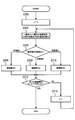
- FIG. 2 is a flowchart showing a procedure of a risk determination process regarding the first succeeding vehicle.
- FIG. 3 is a flowchart showing a procedure of a risk determination process regarding a plurality of subsequent vehicle amounts.
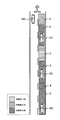
- FIG. 4 is an explanatory diagram showing an outline of highlighting.
- FIG. 5A is an explanatory diagram illustrating an image captured by the camera.
- FIG. 5B is an explanatory diagram illustrating a first display example in which a highlighted image is superimposed on a captured image.
- FIG. 5A is an explanatory diagram illustrating an image captured by the camera.
- FIG. 5B is an explanatory diagram illustrating a first display example in which a highlighted image is superimposed on a captured image.
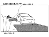
- FIG. 6A is an explanatory diagram illustrating a second display example in which a highlighted image is superimposed on a captured image.
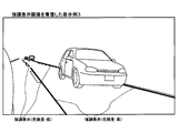
- FIG. 6B is an explanatory diagram illustrating a third display example in which a highlighted image is superimposed on a captured image.
- FIG. 7 is an explanatory diagram illustrating a fourth display example in which a highlighted image is superimposed on a captured image.
- the in-vehicle system 1 of the embodiment includes a driving support device 10, a camera 20 connected to the driving support device 10, a rear vehicle detection unit 21, a speed sensor 22, a blinker switch 23, and a display 30. And a speaker 31.
- the camera 20 images the rear side of a vehicle (hereinafter, the host vehicle 100) on which the in-vehicle system 1 is mounted.
- the camera 20 is connected to the back of the host vehicle 100 so that a lane in which the host vehicle 100 is traveling and a lane adjacent to the lane in which the host vehicle 100 is traveling (hereinafter referred to as an adjacent lane) are within the imaging range. It is attached to the mirror and the side of the car body facing backwards. This camera 20 may be attached to either the left or right side of the vehicle, for example.
- the rear vehicle detection unit 21 detects the presence or position of a subsequent vehicle traveling in the adjacent lane on the rear side of the host vehicle 100 that is the imaging range of the camera 20 by, for example, image recognition with respect to a millimeter wave radar, a laser radar, or a camera image. It is an object detection sensor for detecting (relative position with the host vehicle 100).
- the speed sensor 22 detects the speed of the host vehicle 100 and inputs the detection signal to the driving support device 10.
- the turn signal switch 23 is a switch for operating a turn signal (direction indicator) installed in the host vehicle 100, and outputs a switch signal for operating the turn signal.
- the display 30 is a display device for displaying an image captured by the camera 20 and support information superimposed on the captured image.
- the display 30 is installed at a position that is easily visible from a meter panel in front of the driver's seat or a driver near the A pillar.
- the speaker 31 is a sound output device for outputting a warning sound according to the degree of danger accompanying lane change.
- the driving support device 10 is an information processing device (for example, a microcomputer) mainly configured with a CPU, ROM, RAM, etc. (not shown).
- the driving support device 10 realizes a function of displaying support information related to the degree of danger associated with the own vehicle 100 changing lanes.
- a control unit 11, a display output unit 12, and a warning are provided.
- a sound output unit 13 is provided.
- the control unit 11 is configured to change the lane of the host vehicle 100 to an adjacent lane due to the influence of these succeeding vehicles for the image processing on the captured image acquired from the camera 20 and the plurality of succeeding vehicles detected by the rear vehicle detecting unit 21. Determine the associated risk.
- the determination of the risk level is performed by executing a risk level determination process (see FIG. 2) regarding the first succeeding vehicle and a risk level determination process (refer to FIG. 3) regarding a plurality of subsequent vehicles. Detailed procedures of these processes will be described later.
- control unit 11 creates an image of support information indicating the degree of risk in the road section on which each subsequent vehicle is traveling based on the result of determining the risk level for a plurality of subsequent vehicles.
- the image of the support information is created as a highlighted image that is superimposed on a captured image acquired from the camera 20 and superimposed on an area corresponding to a road section where each subsequent vehicle is traveling.
- the control unit 11 determines that there is an intention to change the lane based on the operation state of the turn signal switch 23, the control unit 11 outputs a warning sound according to the degree of the degree of danger accompanying the lane change.
- the display output unit 12 outputs a support image in which an image of the support information created in the control unit 11 is superimposed on the captured image that has been taken in and is displayed on the display 30.
- the warning sound output unit 13 outputs a warning sound based on the control of the control unit 11 from the speaker 31.
- the control unit 11 determines whether the first subsequent vehicle 101 closest to the own vehicle 100 and the own vehicle 100 among the following vehicles traveling in the adjacent lane. Calculate the distance between and the relative speed. For example, the position of the succeeding vehicle that appears in the captured image may be specified using image recognition for the captured image captured from the camera 20, and the distance between the succeeding vehicle and the host vehicle 100 may be calculated. In S102, the control unit 11 determines the degree of risk related to the first subsequent vehicle 101 based on the distance and relative speed with the first subsequent vehicle 101 calculated in S100 and the speed of the host vehicle 100.
- the control unit 11 proceeds to S104.
- S ⁇ b> 104 the control unit 11 creates an image of support information corresponding to the degree of risk 1 for the first subsequent vehicle 101.
- the control unit 11 proceeds to S106.
- S ⁇ b> 106 the control unit 11 creates an image of support information corresponding to the degree of risk 2 for the first subsequent vehicle 101.
- the control unit 11 proceeds to S112.
- S ⁇ b> 112 the control unit 11 creates an image of support information corresponding to the degree of risk 3 for the first subsequent vehicle 101.
- the control unit 11 displays a partial region of the adjacent lane based on the position where the first succeeding vehicle 101 exists with respect to the captured image acquired from the camera 20 according to the degree of risk.
- An image emphasized in a manner is created as an image of support information.
- the control unit 11 selects any one of the risk levels 1 to 3 as the determination result in S102 for an area on the captured image corresponding to an area separated from the first following vehicle 101 by a predetermined distance forward in the traveling direction. A highlighted display image having a display mode corresponding to this is created.
- the proximity region may change according to, for example, the relative speed between the host vehicle 100 and the first subsequent vehicle 101 or the vehicle speed of the first subsequent vehicle 101.
- the control unit 11 determines whether or not the direction indicator is on based on the operating state of the turn signal switch 23. When the direction indicator is on (S108: YES), the control unit 11 proceeds to S110. In S ⁇ b> 110, the control unit 11 outputs a predetermined warning sound corresponding to the degree of risk 2 determined in S ⁇ b> 102 from the speaker 31 via the warning sound output unit 13. The warning sound generated here is for informing the driver that there is a medium risk of lane change. On the other hand, when it determines with the direction indicator not having been turned on in S108 (S108: NO), the control part 11 complete
- the control unit 11 determines whether or not the direction indicator is on based on the operation state of the blinker switch 23. When the direction indicator is on (S114: YES), the control unit 11 proceeds to S116. In S ⁇ b> 116, the control unit 11 outputs a predetermined warning sound corresponding to the degree of risk 3 determined in S ⁇ b> 102 from the speaker 31 via the warning sound output unit 13. The warning sound generated here is for informing the driver that a high degree of danger is associated with the lane change. On the other hand, when it determines with the direction indicator not having been turned on in S114 (S114: NO), the control part 11 complete
- the control unit 11 sets a counter value (n) for counting the order of the following vehicles to 1.
- n a counter value for counting the order of the following vehicles to 1.
- the control unit 11 based on the detection result obtained from the rear vehicle detection unit 21, the control unit 11 among the subsequent vehicles traveling in the adjacent lane, the n-th subsequent vehicle and the n + 1-th subsequent vehicle from the side closer to the own vehicle 100. And the relative speed between them.
- the position of the succeeding vehicle in the captured image may be specified, and the distance between the succeeding vehicles may be calculated.
- the control unit 11 determines the risk level between these two subsequent vehicles based on the distance and relative speed between the nth and n + 1th subsequent vehicles calculated in S200 and the speed of the host vehicle 100. Determine.
- the shorter the distance between two subsequent vehicles the greater the relative speed in the direction in which the two subsequent vehicles approach, and the higher the speed of the host vehicle 100, the higher the degree of risk.
- the risk is evaluated in three stages of risk 1, risk 2, and risk 3. If it is determined that the risk level is 1 in S204 (S204: risk level 1), the control unit 11 proceeds to S206.
- the control unit 11 creates an image of support information corresponding to the degree of risk 1 for an intermediate region between the n-th and n + 1-th following vehicles.
- the control part 11 determines with the risk level 2 in S204 (S204: risk level 2)
- the control part 11 progresses to S208.
- the control unit 11 creates an image of support information corresponding to the degree of risk 2 for an intermediate region between the nth and n + 1th following vehicles.
- the control part 11 progresses to S210.
- the control unit 11 creates an image of support information corresponding to the degree of risk 3 for an intermediate region between the n-th and n + 1-th following vehicles.
- the control unit 11 displays the adjacent lane region corresponding to the middle of the nth and n + 1th following vehicles in the display mode corresponding to the degree of risk with respect to the captured image acquired from the camera 20.
- An image to be emphasized is created as an image of support information.
- the control unit 11 has a risk level of 1 to 3 as the determination result in S206 for an area on the captured image corresponding to a range that is a predetermined distance from each subsequent vehicle in the middle of the two subsequent vehicles.
- a highlighted display image having a display mode corresponding to any one of them is created.
- a highlighted display image corresponding to the degree of risk 3 is created regardless of the determination result in S206.
- the control unit 11 determines whether or not the risk level has been determined for all detected subsequent vehicles. When there is an undetermined subsequent vehicle (S212: NO), the control unit 11 proceeds to S214. In S214, the control unit 11 increments the counter value (n) by one and returns to S202. On the other hand, when the risk level is determined for all detected subsequent vehicles (S212: YES), the control unit 11 ends this process.
- each region B, D, F corresponding to the adjacent region immediately before and immediately after each of the following vehicles 101 to 103 is assigned a highlight with a risk level of 3.
- the lengths before and after the regions B, D, and F are variable depending on, for example, the relative speed with the host vehicle 100 and other subsequent vehicles, and the vehicle speed of each subsequent vehicle.
- the following vehicle 101 nearest from the own vehicle 100 is determined to have a risk level of 2.
- an emphasis display of risk level 2 is assigned to the area A that is separated from the following vehicle 101 by the area B ahead.
- a risk level 1 is determined between the following vehicle 101 and the following vehicle 102.
- the highlighting of the risk level 1 is assigned to the region C corresponding to the gap between the region B that is the proximity region of the following vehicle 101 and the region D that is the proximity region of the following vehicle 102.
- the risk level 3 is determined between the following vehicle 102 and the following vehicle 103.
- an emphasis display of risk level 3 is assigned to a region E corresponding to a gap between a region D that is a proximity region of the following vehicle 102 and a region F that is a proximity region of the following vehicle 103.
- the gap between the region D and the region F is narrower than the entire length of the host vehicle 100. Therefore, when the lane is changed so that the own vehicle 100 enters the gap, there is a possibility of interfering with the proximity region of the following vehicles 102 and 103. In this way, when the gap between the adjacent areas of the two following vehicles is extremely narrow, the highlighting of the risk level 3 is assigned.
- FIG. 5A is an example of a captured image acquired from the camera 20.
- a part of the vehicle body of the host vehicle 100 is shown at the left end, and a landscape of the adjacent lane of the host vehicle 100 is shown in a region on the right side thereof.
- the three captured vehicles that travel in a line on the adjacent lane behind the host vehicle 100 are captured in the captured image.
- these succeeding vehicles are identified as the first succeeding vehicle 101, the second succeeding vehicle 102, and the third succeeding vehicle 103 in order from the closest to the host vehicle 100.
- FIG. 5B is a first display example in which a planar highlight image is superimposed on the captured image shown in FIG. 5A.
- an expression method is used in which the entire area where the degree of danger on the road surface of the adjacent lane is to be displayed is covered with a pattern such as solid paint or shaded.
- These highlighted images make it possible to determine the degree of risk by changing the color, pattern, shading, transparency, etc. of the symbol in accordance with the degree of risk.
- the highlighted image is not drawn in a portion overlapping the subsequent vehicle in the captured image.
- a method of expressing the degree of danger continuously using color, light and dark gradations, and gradation of light and shade may be used.
- a portion (or region) overlapping the highlighted image and the following vehicle is determined by recognizing the shape of the following vehicle by image recognition, for example.
- FIG. 6A is a second display example in which a linear highlight image is superimposed on the captured image shown in FIG. 5A.
- a line representing a range of risk is drawn by drawing a line such as a solid line, dotted line, or broken line in parallel along the road surface at the front and rear ends of the area where the risk should be displayed on the road surface of the adjacent lane. The method is used.
- FIG. 6B is a third display example in which a linear highlight display image is superimposed on the captured image shown in FIG. 5A.
- a method of expressing the range of risk by drawing a line such as a solid line, dotted line, or broken line along the side edges (boundary of the adjacent lane) of the area where the risk should be displayed on the road surface of the adjacent lane is used. It has been. More specifically, this highlighted image is drawn as a parallel line segment along a white line that divides the lane drawn on the road surface.
- the highlighted images illustrated in FIGS. 6A and 6B make it possible to determine the degree of risk by changing the color, thickness, pattern (solid line, dotted line, broken line), etc. of the line according to the degree of risk. . In addition, these highlighted images are not drawn in a portion overlapping the subsequent vehicle in the image.
- FIG. 7 is a fourth display example in which a highlighted image is superimposed on a captured image different from FIG. 5A.
- a succeeding vehicle is present in a blind spot that is on the adjacent lane immediately beside the host vehicle 100 and is outside the imaging range of the camera 20.
- a situation in which the first succeeding vehicle 101 overtakes the host vehicle 100 from the situation illustrated in FIG. 5A out of the imaging range of the camera 20 corresponds to this.
- a highlighted image representing a high-risk state is displayed superimposed on the captured image.
- it may be configured to display the warning mark M1 indicating that the following vehicle exists outside the display range.
- an area having a predetermined size or a line segment having a predetermined length may be displayed as support information.
- the area of a predetermined size or the line segment having a predetermined length may be defined by a line segment plotting the average appearance of adjacent lanes displayed on the captured image.
- a region having a predetermined size or a line segment having a predetermined length may be displayed on the captured image and defined by the width of the following vehicle traveling in the adjacent lane.
- the highlighted image corresponding to the risk level of each stage is displayed from the high risk area to the low risk area.
- the highlighted image may be displayed for a high risk area and nothing may be displayed for a low risk area.
- the vehicle-mounted system 1 has the following effects.
- a highlighted image that can determine the degree of the risk associated with the lane change is displayed superimposed on the captured image acquired from the camera 20. it can.
- the highlighted image can be displayed in association with the adjacent areas before and after each succeeding vehicle and the area between the succeeding vehicles.
- a warning sound corresponding to the degree of danger can be generated and the display mode of the highlighted image can be changed.
- the driver can clearly understand the danger associated with the lane change.
- the camera 20 corresponds to the imaging unit of the present disclosure.
- the rear vehicle detection unit 21 corresponds to the situation acquisition unit of the present disclosure.
- the display 30 corresponds to the display unit of the present disclosure.
- the control unit 11 and the display output unit 12 correspond to the display control unit of the present disclosure. Note that S100, S200, and the control unit 11 correspond to a calculation unit of the present disclosure. S102, S204, and the control unit 11 correspond to the evaluation unit of the present disclosure. S108, S114, and the driving support device 10 correspond to the operation determination unit of the present disclosure.
- the imaging unit that captures the adjacent lane on the rear side of the host vehicle, the presence / absence of the plurality of subsequent vehicles that travel on the adjacent lane on the rear side of the host vehicle, and the plurality of subsequent vehicles
- a driving support device that is communicably connected to a status acquisition unit that acquires information regarding the position of the vehicle and a display unit that displays an image.
- the driving support device includes an image acquisition unit that acquires a captured image captured by the imaging unit, a distance and a relative speed between the host vehicle and the following vehicle, and a distance between the subsequent vehicles based on the information acquired by the situation acquisition unit.
- a calculation unit that calculates a distance and a relative speed, and an evaluation that evaluates a risk associated with the own vehicle changing the lane to the adjacent lane for a plurality of subsequent vehicles based on the distance and the relative speed calculated by the calculation unit
- a display control unit that displays on the display unit a support image that is superimposed on a corresponding position on the captured image.
- the driving support device of the present disclosure based on the degree of risk evaluated for a plurality of subsequent vehicles traveling in the adjacent lane, support information associated with a road section based on a position where the plurality of subsequent vehicles exist is captured image. It can be displayed superimposed on the top. By doing in this way, the driver
- each section is expressed as S100, for example. Further, each section can be divided into a plurality of subsections, while a plurality of sections can be combined into one section.
- each of the above sections or a combination thereof includes not only (i) a section of software combined with a hardware unit (eg, a computer), but also (ii) hardware (eg, an integrated circuit, As a section of (wiring logic circuit), it can be realized with or without the function of related devices.
- the hardware section can be configured inside the microcomputer.
- the image acquisition unit, the calculation unit, the evaluation unit, and the display control unit are classified for convenience by focusing on the functions of the control unit 11. It does not mean that the inside is physically divided into portions corresponding to the respective “parts”.
Landscapes
- Engineering & Computer Science (AREA)
- Physics & Mathematics (AREA)
- General Physics & Mathematics (AREA)
- Multimedia (AREA)
- Theoretical Computer Science (AREA)
- Mechanical Engineering (AREA)
- Computer Vision & Pattern Recognition (AREA)
- Traffic Control Systems (AREA)
Abstract
運転支援装置(10)は撮像部(20)によって撮像された撮像画像を取得する画像取得部(11)と、自車両(100)と後続車両との距離及び相対速度と、後続車両間の距離及び相対速度とを算出する算出部(11)と、複数の後続車両について、自車両(100)が隣接車線へ車線変更することに伴う危険度を評価する評価部(11)と、車線変更に伴う危険度に関する支援情報を、複数の後続車両が存在する位置を基準とする道路区間に対応付けて作成し、支援情報を撮像画像上における対応する位置に重畳した支援画像を、表示部(30)に表示させる表示制御部(11,12)と、を備える。
Description
本出願は、2013年11月27日に出願された日本国特許出願2013-245089号に基づくものであり、ここにその記載内容を参照により援用する。
本開示は、自車両の後側方を撮影した映像を表示する運転支援装置に関する。
カメラで自車両の後側方の隣接車線を撮影し、撮影によって得られた画像上に車線変更等が可能か否かの目安となるガイド線等の運転支援情報を重畳させて表示する技術が提案されている(例えば、特許文献1参照)。
本願発明者らは、運転支援装置に関して以下を見出した。
特許文献1に記載の技術では、自車両の後側方の隣接車線を走行する直近1台の後続車両を基準に、車線変更等が可能か否かの目安となるガイド線を表示するようになっている。この技術によると、直近の後続車両に対応するガイド線しか表示されないため、運転者が直近の後続車両の前で車線変更をすることを断念したときに、その後続車両の後で車線変更が可能であるか否かを前もって判断する目安が運転者に与えられないかもしれない。そのため、当該直近の後続車両に追い抜かれてから、運転者は次の直近の後続車両に対応するガイド線を参考にして、車線変更が可能であるか否かを判断しなければならないおそれがある。
本開示は、上記問題を解決するためになされたものであり、複数の後続車両について、車線変更に伴う危険性を前もって判断することができる支援情報を表示するための技術を提供することを目的とする。
本開示の一態様に係る運転支援装置は、自車両の後側方の隣接車線を撮像する撮像部と、自車両の後側方の隣接車線を走行する複数の後続車両に関する情報を取得する状況取得部と、画像を表示する表示部と通信可能に接続される。本開示の運転支援装置は、画像取得部、算出部、評価部、及び表示制御部を備える。
画像取得部は、撮像部によって撮像された撮像画像を取得する。算出部は、状況取得部により取得された情報に基づいて、自車両と後続車両との距離及び相対速度と、後続車両間の距離及び相対速度とを算出する。評価部は、算出部により算出された距離及び相対速度に基づき、複数の後続車両について、自車両が隣接車線へ車線変更することに伴う危険度を評価する。表示制御部は、評価部による危険度の評価結果に基づき、車線変更に伴う危険度に関する支援情報を、複数の後続車両が存在する位置を基準とする道路区間に対応付けて作成する。そして、表示制御部は、作成した支援情報を撮像画像上における対応する位置に重畳した支援画像を、表示部に表示させる。
本開示の運転支援装置によれば、隣接車線を走行する複数の後続車両について評価した危険度に基づき、複数の後続車両が存在する位置を基準とする道路区間に対応付けた支援情報を撮像画像上に重畳して表示させることができる。このようにすることで、運転者は、直近1台の後続車両だけでなくそれ以降の後続車両についても、車線変更に伴う危険性を前もって把握することができる。
本開示についての上記および他の目的、特徴や利点は、添付の図面を参照した下記の詳細な説明から、より明確になる。添付図面において、
図1は、運転支援装置の構成を表すブロック図であり、
図2は、直近1台目の後続車両に関する危険度判定処理の手順を表すフローチャートであり、
図3は、複数の後続車量間に関する危険度判定処理の手順を表すフローチャートであり、
図4は、強調表示の概要を表す説明図であり、
図5Aは、カメラによる撮像画像を表す説明図であり、
図5Bは、撮像画像に強調表示画像を重畳した第1表示例を表す説明図であり、
図6Aは、撮像画像に強調表示画像を重畳した第2表示例を表す説明図であり、
図6Bは、撮像画像に強調表示画像を重畳した第3表示例を表す説明図であり、
図7は、撮像画像に強調表示画像を重畳した第4表示例を表す説明図である。
以下、本開示の一実施形態を図面に基づいて説明する。なお、本開示は下記の実施形態に限定されるものではなく様々な態様にて実施することが可能である。
[運転支援システムの構成の説明]
図1に示すように、実施形態の車載システム1は、運転支援装置10と、この運転支援装置10に接続されているカメラ20、後方車両検知部21、速度センサ22、ウインカスイッチ23、ディスプレイ30、及びスピーカ31とを備える。
図1に示すように、実施形態の車載システム1は、運転支援装置10と、この運転支援装置10に接続されているカメラ20、後方車両検知部21、速度センサ22、ウインカスイッチ23、ディスプレイ30、及びスピーカ31とを備える。
カメラ20は、車載システム1が搭載される車両(以下、自車両100)の後側方を撮像するものである。このカメラ20は、主に自車両100が走行している車線と自車両100が走行している車線に隣接する車線(以下、隣接車線)が撮像範囲に入るように、例えば自車両100のバックミラーや車体側面に後方に向けて取付けられている。このカメラ20は、例えば、車両の左右どちら側に取付けられていてもよい。
後方車両検知部21は、例えば、ミリ波レーダやレーザレーダ、カメラ映像に対する画像認識により、カメラ20の撮像範囲である自車両100の後側方の隣接車線を走行する後続車両の存在や、位置(自車両100との相対位置)を検知する物体検知用センサである。速度センサ22は、自車両100の速度を検知し、その検知信号を運転支援装置10に入力する。ウインカスイッチ23は、自車両100に装備されたウインカ(方向指示器)を操作するためのスイッチであり、ウインカを作動させるためのスイッチ信号を出力する。
ディスプレイ30は、カメラ20による撮像画像、及びその撮像画像上に重畳された支援情報を表示するための表示装置である。このディスプレイ30は、例えば運転席前方のメータパネルやAピラー付近の運転者から視認しやすい位置に設置される。スピーカ31は、車線変更に伴う危険度に応じた警告音を出力するための音声出力装置である。
運転支援装置10は、図示しないCPU,ROM,RAM等を中心に構成された情報処理装置(例えば、マイクロコンピュータ)。この運転支援装置10は、自車両100が車線変更することに伴う危険度に関する支援情報を表示する機能を実現するものであり、そのための機能的構成として、制御部11、表示出力部12及び警告音出力部13を備える。
制御部11は、カメラ20から取得した撮像画像に対する画像処理や後方車両検知部21により検知された複数の後続車両について、これらの後続車両の影響により自車両100が隣接車線に車線変更することに伴う危険度を判定する。危険度の判定は、直近1台目の後続車両に関する危険度判定処理(図2参照)、及び、複数の後続車両間に関する危険度判定処理(図3参照)を実行することで行われる。これらの処理の詳細な手順については後述する。
また、制御部11は、複数の後続車両について危険度を判定した結果に基づき、各後続車両が走行している道路区間における危険度の度合を表す支援情報の画像を作成する。この支援情報の画像は、カメラ20から取得した撮像画像上において、各後続車両が走行している道路区間に相当する領域に重畳して施される強調表示画像として作成される。また、制御部11は、ウインカスイッチ23の操作状態に基づいて車線変更の意図があると判断したときに、車線変更に伴う危険度の度合に応じて警告音を出力させる。 表示出力部12は、取込んだ撮像画像上に制御部11において作成された支援情報の画像が重畳された支援画像を、ディスプレイ30に出力して表示させる。警告音出力部13は、制御部11の制御に基づく警告音をスピーカ31から音声出力する。
[直近1台目の後続車両に関する危険度判定処理]
直近1台目の後続車両に関する危険度判定処理の手順について、図2のフローチャートを参照しながら説明する。この処理は、運転支援装置10の制御部11が所定の制御周期で繰返し実行する。
直近1台目の後続車両に関する危険度判定処理の手順について、図2のフローチャートを参照しながら説明する。この処理は、運転支援装置10の制御部11が所定の制御周期で繰返し実行する。
S100では、制御部11は、後方車両検知部21から得られた検知結果に基づき、隣接車線を走行する後続車両のうち、自車両100から最も近い1番目の後続車両101と自車両100との間の距離及び相対速度を算出する。例えば、カメラ20から取込んだ撮像画像に対する画像認識を用いて、撮像画像に写る後続車両の位置を特定し、後続車両と自車両100との距離を算出してもよい。 S102では、制御部11は、S100で算出した1番目の後続車両101との距離及び相対速度と、自車両100の速度とに基づいて、1番目の後続車両101に関する危険度を判定する。ここでは、例えば、自車両100と後続車両との距離が短いほど、また、自車両100と後続車両とが接近する方向に相対速度が大きいほど、また、自車両100の速度が大きいほど、危険度が高く評価される。なお、本実施形態では、危険度1(低程度)、危険度2(中程度)、危険度3(高程度)の3段階で危険度を評価するものとする。 1番目の後続車両101について危険度1と判定した場合(S102:危険度1)、制御部11はS104に進む。S104では、制御部11は、1番目の後続車両101について危険度1に相当する支援情報の画像を作成する。一方、1番目の後続車両101について危険度2と判定した場合(S102:危険度2)、制御部11はS106に進む。S106では、制御部11は、1番目の後続車両101について危険度2に相当する支援情報の画像を作成する。一方、1番目の後続車両101について危険度3と判定した場合(S102:危険度3)、制御部11はS112に進む。S112では、制御部11は、1番目の後続車両101について危険度3に相当する支援情報の画像を作成する。
S104,S106,S112では、制御部11は、カメラ20から取得した撮像画像に対して、1番目の後続車両101が存在する位置を基準とする隣接車線の一部領域を危険度に応じた表示態様で強調する画像を支援情報の画像として作成する。ここでは、制御部11は、1番目の後続車両101から進行方向前方に所定距離を隔てた領域に該当する撮像画像上の領域に対して、S102における判定結果である危険度1~3の何れかに相当する表示態様の強調表示画像を作成する。また、1番目の後続車両101の進行方向前後の近接領域に該当する撮像画像上の領域に対して、S102における判定結果に関わらず、危険度3に相当する表示態様の強調表示画像を作成する。近接領域は、例えば、自車両100と1番目の後続車両101との相対速度や、1番目の後続車両101の車速に応じて変化してもよい。
S108では、制御部11は、ウインカスイッチ23の操作状態に基づき、方向指示器がオンになっているか否かを判定する。方向指示器がオンになっている場合(S108:YES)、制御部11はS110に進む。S110では、制御部11は、S102で判定された危険度2に対応する所定の警告音を、警告音出力部13を介してスピーカ31から出力する。ここで発生する警告音は、車線変更に中程度の危険性が伴う旨を運転者に知らせるためのものである。一方、S108において方向指示器がオンになっていないと判定した場合(S108:NO)、制御部11は本処理を終了する。
S114では、制御部11は、ウインカスイッチ23の操作状態に基づき、方向指示器がオンになっているか否かを判定する。方向指示器がオンになっている場合(S114:YES)、制御部11はS116に進む。S116では、制御部11は、S102で判定された危険度3に対応する所定の警告音を、警告音出力部13を介してスピーカ31から出力する。ここで発生する警告音は、車線変更に高程度の危険性が伴う旨を運転者に知らせるためのものである。一方、S114において方向指示器がオンになっていないと判定した場合(S114:NO)、制御部11は本処理を終了する。 [複数の後続車両間に関する危険度判定処理]
複数の後続車両間に関する危険度判定処理の手順について、図3のフローチャートを参照しながら説明する。この処理は、運転支援装置10の制御部11が所定の制御周期で繰返し実行する。
複数の後続車両間に関する危険度判定処理の手順について、図3のフローチャートを参照しながら説明する。この処理は、運転支援装置10の制御部11が所定の制御周期で繰返し実行する。
S200では、制御部11は、後続車両の順番を数えるためのカウンタの値(n)を1にセットする。S202では、制御部11は、後方車両検知部21から得られた検知結果に基づき、隣接車線を走行する後続車両のうち、自車両100から近い方からn番目の後続車両とn+1番目の後続車両との間の距離及び相対速度を算出する。ここでは、カメラ20から取得した撮像画像に対する画像認識を用いて、撮像画像に写る後続車両の位置を特定し、後続車両間の距離を算出してもよい。 次のS204では、制御部11は、S200で算出したn番目とn+1番目の後続車両間の距離及び相対速度と、自車両100の速度とに基づいて、これら2台の後続車両間に関する危険度を判定する。ここでは、例えば、2台の後続車両間の距離が短いほど、また、2台の後続車両が接近する方向に相対速度が大きいほど、また、自車両100の速度が大きいほど、危険度が高く評価される。ここでは、危険度1、危険度2、危険度3の3段階で危険度を評価する。 S204において危険度1と判定した場合(S204:危険度1)、制御部11はS206に進む。S206では、制御部11は、n番目とn+1番目の後続車両の中間の領域について、危険度1に相当する支援情報の画像を作成する。一方、S204において危険度2と判定した場合(S204:危険度2)、制御部11はS208に進む。S208では、制御部11は、n番目とn+1番目の後続車両の中間の領域について、危険度2に相当する支援情報の画像を作成する。一方、S204において危険度3と判定した場合(S204:危険度3)、制御部11はS210に進む。S210では、制御部11は、n番目とn+1番目の後続車両の中間の領域について、危険度3に相当する支援情報の画像を作成する。
S206,S208,S210では、制御部11は、カメラ20から取得した撮像画像に対して、n番目とn+1番目の後続車両の中間に相当する隣接車線の領域を、危険度に応じた表示態様で強調する画像を支援情報の画像として作成する。ここでは、制御部11は、2台の後続車両の中間において各後続車両から所定距離を隔てた範囲に該当する撮像画像上の領域に対して、S206における判定結果である危険度1~3の何れかに相当する表示態様の強調表示画像を作成する。また、各後続車両の進行方向前後の近接領域に該当する撮像画像上の領域に対して、S206における判定結果に関わらず、危険度3に相当する表示態様の強調表示画像を作成する。
次のS212では、制御部11は、検知されている全ての後続車両について危険度の判定を行ったか否かを判定する。未判定の後続車両が存在する場合(S212:NO)、制御部11はS214に進む。S214では、制御部11は、カウンタの値(n)を1つカウントアップしてS202に戻る。一方、検知されている全ての後続車両について危険度の判定を行った場合(S212:YES)、制御部11は本処理を終了する。
上述の「直近1台目の後続車両に関する危険度判定処理」(図2参照)、及び「複数の後続車両間に関する危険度判定処理」(図3参照)において作成された支援情報の画像は、カメラ20から取込んだ撮像画像上の対応する位置に重畳され、表示出力部12を介してディスプレイ30に表示される。
[危険度の判定結果の具体例]
上述の「直近1台目の後続車両に関する危険度判定処理」(図2参照)、及び「複数の後続車両間に関する危険度判定処理」(図3参照)による処理結果に基づく、危険度の分布状況の具体例について、図4を参照しながら説明する。図4の事例では、自車両100の右側の隣接車線の後方において、3台の後続車両101~103が自車両100と同じ方向に走行している状況を想定している。
上述の「直近1台目の後続車両に関する危険度判定処理」(図2参照)、及び「複数の後続車両間に関する危険度判定処理」(図3参照)による処理結果に基づく、危険度の分布状況の具体例について、図4を参照しながら説明する。図4の事例では、自車両100の右側の隣接車線の後方において、3台の後続車両101~103が自車両100と同じ方向に走行している状況を想定している。
図4に例示されるとおり、隣接車線上において、各後続車両101~103の直前及び直後の近接領域に相当する各領域B,D,Fについては、危険度3の強調表示が割当てられる。領域B,D,Fの前後の長さは、例えば、自車両100や他の後続車両との相対速度や、各後続車両の車速に応じて可変とする。
自車両100から直近の後続車両101について、危険度2と判定されたと想定する。この場合、後続車両101から前方に領域Bを隔てた領域Aについて、危険度2の強調表示が割当てられる。また、後続車両101と後続車両102との中間について、危険度1と判定されたと想定する。この場合、後続車両101の近接領域である領域Bと、後続車両102の近接領域である領域Dとの隙間に相当する領域Cについて、危険度1の強調表示が割当てられる。
また、後続車両102と後続車両103との中間について、危険度3と判定されたと想定する。この場合、後続車両102の近接領域である領域Dと、後続車両103の近接領域である領域Fとの隙間に相当する領域Eについて、危険度3の強調表示が割当てられる。なお、領域Dと領域Fとの隙間は、自車両100の全長よりも狭くなっている。そのため、この隙間に自車両100が入るように車線変更した場合、後続車両102,103の近接領域に干渉するおそれがある。このように、2台の後続車両の近接領域の隙間が著しく狭い場合、危険度3の強調表示が割当てられるものとする。
[強調表示画像の表示例]
カメラ20から取込んだ撮像画像上に強調表示画像を重畳した画像の表示例について、表現方法の異なるいくつかの事例を図5A、図5B、図6A,図6Bを参照しながら説明する。
カメラ20から取込んだ撮像画像上に強調表示画像を重畳した画像の表示例について、表現方法の異なるいくつかの事例を図5A、図5B、図6A,図6Bを参照しながら説明する。
図5Aは、カメラ20から取得した撮像画像の一例である。この撮像画像には、左端に自車両100の車体の一部が写り込んでおり、それより右側の領域には自車両100の隣接車線の風景が写っている。また、この撮像画像には、自車両100より後方の隣接車線上を一列に走行する3台の後続車両が写っているものとする。以下、これらの後続車両については、自車両100から近いものから順に1番目の後続車両101、2番目の後続車両102、3番目の後続車両103と識別する。
図5Bは、図5Aで示される撮像画像上に、面状の強調表示画像を重畳した第1の表示例である。この事例では、隣接車線の路面上における危険度を表示すべき領域全体を、べた塗や網掛け等の図柄で面状に覆う表現方法が用いられている。これらの強調表示画像は、危険度の程度に応じて図柄の色や模様、濃淡、透明度等を変えることで危険度の程度を判別可能にする。また、この強調表示画像は、撮像画像内の後続車両と重なる部分には描画されない。また、危険度の程度を領域ごとに段階的に表現する方法とは別に、色や明暗、濃淡のグラデーションを使って連続的に表現する方法であってもよい。
なお、撮像画像内において、強調表示画像と後続車両と重なる部分(または領域)は、例えば、画像認識により後続車両の形状を認識することで判定される。
図6Aは、図5Aで示される撮像画像上に線状の強調表示画像を重畳した第2の表示例である。この事例では、隣接車線の路面上における危険度を表示すべき領域の前端と後端に、実線や点線、破線等の線分を道路面に沿って平行に引いて危険度の範囲を表す表現方法が用いられている。また、図6Bは、図5Aで示される撮像画像上に線状の強調表示画像を重畳した第3の表示例である。この事例では、隣接車線の路面上における危険度を表示すべき領域の両側端(隣接車線の境界)に沿って実線や点線、破線等の線を引いて危険度の範囲を表す表現方法が用いられている。より具体的には、この強調表示画像は、道路面上に引かれている車線を区分する白線に沿う平行な線分として描画される。図6A及び図6Bに例示される強調表示画像は、危険度の程度に応じて線の色や太さ、模様(実線、点線、破線)等を変えることで危険度の程度を判別可能にする。また、これらの強調表示画像は、画像内の後続車両と重なる部分には描画されない。
図7は、図5Aとは別の撮像画像上に強調表示画像を重畳した第4の表示例である。この事例では、自車両100からすぐ横の隣接車線上であって、カメラ20の撮像範囲外となる死角に後続車両が存在する状況を想定している。例えば、図5Aに例示される状況から1番目の後続車両101が自車両100を追い抜く過程で、カメラ20の撮像範囲からフレームアウトした状況がこれに相当する。このような場合、撮像画像からフレームアウトした後続車両に由来する危険度の高い領域が表示範囲内に残っていれば、危険度が高い状態を表す強調表示画像が撮像画像に重畳して表示される。このとき、表示範囲外に存在する後続車両に由来する強調表示画像を表示する場合、表示範囲外に後続車両が存在することを示す警告マークM1を表示するように構成することが考えられる。
なお、道路面上において車線を区別する白線が検出されない場合は、予め決められた大きさの領域または予め決められた長さの線分を支援情報として表示してもよい。この場合、予め決められた大きさの領域または予め決められた長さの線分は、撮像画像上に表示される隣接車線の平均的な見え方をプロットした線分により規定されればよい。代わりに、予め決められた大きさの領域または予め決められた長さの線分は、撮像画像上に表示され、隣接車線を走行する後続車両の幅により規定されてもよい。
[変形例]
直近1台目の後続車両に関する危険度判定処理(図2参照)のS108,S114において方向指示器が作動していると判定されたときに、撮像画像上に重畳して表示している強調表示画像の表示態様を変化させるようにしてもよい。具体的には、方向指示器の作動中に強調表示画像の色を変えたり明滅させて、通常よりも表示を強調することが考えられる。このようにすることで、運転者に車線変更する意図があるときに、車線変更に伴う危険性を認識しやすくできる。
直近1台目の後続車両に関する危険度判定処理(図2参照)のS108,S114において方向指示器が作動していると判定されたときに、撮像画像上に重畳して表示している強調表示画像の表示態様を変化させるようにしてもよい。具体的には、方向指示器の作動中に強調表示画像の色を変えたり明滅させて、通常よりも表示を強調することが考えられる。このようにすることで、運転者に車線変更する意図があるときに、車線変更に伴う危険性を認識しやすくできる。
図5A、図5B、図6A及び図6Bの表示例では、危険度の高い領域から低い領域まで各段階の危険度に対応する強調表示画像を表示する事例について説明した。これとは別に、危険度が高い領域については強調表示画像を表示し、危険度が低い領域については何も表示しないようにしてもよい。
実施形態の車載システム1によれば、以下の効果を奏する。
隣接車線を走行する複数の後続車両について評価した危険度に基づき、車線変更に伴う危険度の程度を判別可能な強調表示画像を、カメラ20から取得した撮像画像上に重畳して表示させることができる。また、強調表示画像を、各後続車両の前後の近接領域や後続車両間の領域に対応付けて表示することができる。このようにすることで、運転者は、直近1台の後続車両だけでなくそれ以降の後続車両についても、車線変更に伴う危険性を前もって把握することができる。
また、方向指示器の作動に基づいて、危険度に応じた警告音を発生したり強調表示画像の表示態様を変化させることができる。これにより、運転者に車線変更の意図があるときに、車線変更に伴う危険性を運転者に明確に把握させることができる。
カメラ20は、本開示の撮像部に対応する。後方車両検知部21は、本開示の状況取得部に対応する。ディスプレイ30は、本開示の表示部に対応する。制御部11と表示出力部12は、本開示の表示制御部に対応する。なお、S100とS200と制御部11は、本開示の算出部に対応する。S102とS204と制御部11は、本開示の評価部に対応する。S108とS114と運転支援装置10は、本開示の作動判別部に対応する。
本開示の一態様によれば、自車両の後側方の隣接車線を撮像する撮像部と、自車両の後側方の隣接車線を走行する複数の後続車両の有無、及び当該複数の後続車両の位置に関する情報を取得する状況取得部と、画像を表示する表示部と通信可能に接続された運転支援装置が提供される。運転支援装置は、撮像部によって撮像された撮像画像を取得する画像取得部と、状況取得部により取得された情報に基づいて、自車両と後続車両との距離及び相対速度と、後続車両間の距離及び相対速度とを算出する算出部と、算出部により算出された距離及び相対速度に基づき、複数の後続車両について、自車両が前記隣接車線へ車線変更することに伴う危険度を評価する評価部と、評価部による危険度の評価結果に基づき、車線変更に伴う危険度に関する支援情報を、複数の後続車両が存在する位置を基準とする道路区間に対応付けて作成し、作成した支援情報を撮像画像上における対応する位置に重畳した支援画像を、表示部に表示させる表示制御部と、を備える。
本開示の運転支援装置によれば、隣接車線を走行する複数の後続車両について評価した危険度に基づき、複数の後続車両が存在する位置を基準とする道路区間に対応付けた支援情報を撮像画像上に重畳して表示させることができる。このようにすることで、運転者は、直近1台の後続車両だけでなくそれ以降の後続車両についても、車線変更に伴う危険性を前もって把握することができる。
ここで、この出願に記載されるフローチャート、あるいは、フローチャートの処理は、複数のセクション(あるいはステップと言及される)から構成され、各セクションは、たとえば、S100と表現される。さらに、各セクションは、複数のサブセクションに分割されることができる、一方、複数のセクションが合わさって一つのセクションにすることも可能である。
また、上記の複数のセクションの各々あるいは組合わさったものは、(i)ハードウエアユニット(例えば、コンピュータ)と組み合わさったソフトウエアのセクションのみならず、(ii)ハードウエア(例えば、集積回路、配線論理回路)のセクションとして、関連する装置の機能を含みあるいは含まずに実現できる。さらに、ハードウエアのセクションは、マイクロコンピュータの内部に構成されることもできる。
なお、本実施形態において、画像取得部、算出部、評価部、及び表示制御部は、制御部11の有する機能に着目して、その内部を便宜的に分類したものであり、制御部11の内部が、それぞれの「部」に対応する部分に物理的に区分されていることを意味するものではない。
以上、本開示に係る運転支援装置の実施形態、構成、態様を例示したが、本開示に係る実施形態、構成、態様は、上述した各実施形態、各構成、各態様に限定されるものではない。例えば、異なる実施形態、構成、態様にそれぞれ開示された技術的部を適宜組み合わせて得られる実施形態、構成、態様についても本開示に係る実施形態、構成、態様の範囲に含まれる。
Claims (12)
- 自車両(100)の後側方の隣接車線を撮像する撮像部(20)と、自車両(100)の後側方の隣接車線を走行する複数の後続車両の有無、及び当該複数の後続車両の位置に関する情報を取得する状況取得部(21)と、画像を表示する表示部(30)と通信可能に接続された運転支援装置(10)であって、
前記撮像部(20)によって撮像された撮像画像を取得する画像取得部(11)と、
前記状況取得部(21)により取得された情報に基づいて、自車両(100)と前記後続車両との距離及び相対速度と、前記後続車両間の距離及び相対速度とを算出する算出部(11)と、
前記算出部(11)により算出された距離及び相対速度に基づき、前記複数の後続車両について、自車両(100)が前記隣接車線へ車線変更することに伴う危険度を評価する評価部(11)と、
前記評価部(11)による危険度の評価結果に基づき、車線変更に伴う危険度に関する支援情報を、前記複数の後続車両が存在する位置を基準とする道路区間に対応付けて作成し、前記作成した支援情報を前記撮像画像上における対応する位置に重畳した支援画像を、前記表示部(30)に表示させる表示制御部(11,12)と、
を備える運転支援装置。 - 請求項1に記載の運転支援装置において、
前記表示制御部(11,12)は、各後続車両が存在する位置の直前及び直後の道路区間に対応する前記支援情報を作成し、当該作成した支援情報を前記撮像画像に写る各後続車両の直前及び直後の道路区間に重畳した支援画像を表示させる運転支援装置。 - 請求項1又は請求項2に記載の運転支援装置において、
前記表示制御部(11,12)は、連続する2台の前記後続車両の中間の道路区間に対応する前記支援情報を作成し、当該作成した支援情報を前記撮像画像上に写る2台の前記後続車両の中間の道路区間の位置に重畳した支援画像を表示させる運転支援装置。 - 請求項1ないし請求項3の何れか1項に記載の運転支援装置において、
前記表示制御部(11,12)は、前記支援情報として、車線変更に伴う危険度の程度を判別可能な態様の図柄を前記撮像画像上に重畳した支援画像を表示させる運転支援装置。 - 請求項4に記載の運転支援装置において、
道路面上において車線を区別する白線が検出されない場合、予め決められた大きさの領域または予め決められた長さの線分を支援情報として表示させる運転支援装置。 - 請求項5に記載の運転支援装置において、
前記予め決められた大きさの領域または予め決められた長さの線分は、前記撮像画像上に表示される隣接車線の平均的な見え方をプロットした線分により規定される運転支援装置。 - 請求項5に記載の運転支援装置において、
前記予め決められた大きさの領域または予め決められた長さの線分は、前記撮像画像上に表示され、隣接車線を走行する後続車両の幅により規定される運転支援装置。 - 請求項4に記載の運転支援装置において、
前記表示制御部(11,12)は、車線変更に伴う危険度の程度に応じて、前記支援情報の図柄の色、模様、又は透明度を変えた前記支援情報を作成し、かつ、前記撮像画像内において後続車両と重なる領域を除いた領域に、前記支援情報を描く運転支援装置。 - 請求項4に記載の運転支援装置において、
前記表示制御部(11,12)は、車線変更に伴う危険度の程度に応じて、色、太さ、又は模様を変えた線分を、前記撮像画像内の道路面上に沿って引いた前記支援情報を作成し、かつ、前記撮像画像内において後続車両と重なる領域を除いた領域に、前記線分を描く運転支援装置。 - 請求項4に記載の運転支援装置において、
前記表示制御部(11,12)は、車線変更に伴う危険度の程度に応じて、色、太さ、又は模様を変えた線分を、前記撮像画像内の道路面上において車線を区分する白線に沿って引いた前記支援情報を作成し、かつ、前記撮像画像内において後続車両と重なる領域いた領域に、前記線分を描く運転支援装置。 - 請求項1ないし請求項10の何れか1項に記載の運転支援装置において、
自車両(100)に装備されている方向指示器(23)の作動状況を判別する作動判別部(10)と、
前記作動判別部(10)によって方向指示器(23)が作動していると判別されたときに、前記評価部(11)によって評価された危険度に応じた警告音を、所定の音声出力部(31)に出力させる警告部(11,13)と、
を備える運転支援装置。 - 請求項1ないし請求項11の何れか1項に記載の運転支援装置において、
自車両(100)に装備されている方向指示器(23)の作動状況を判別する作動判別部(10)を備え、
前記表示制御部(11,12)は、前記作動判別部(10)によって方向指示器(23)が作動していること判別されたときに、前記支援情報の表示態様を強調させる運転支援装置。
Priority Applications (3)
| Application Number | Priority Date | Filing Date | Title |
|---|---|---|---|
| CN201480064367.8A CN105765641A (zh) | 2013-11-27 | 2014-10-30 | 驾驶辅助装置 |
| DE112014005398.8T DE112014005398B4 (de) | 2013-11-27 | 2014-10-30 | Fahrunterstützungsvorrichtung |
| US15/038,490 US9852635B2 (en) | 2013-11-27 | 2014-10-30 | Driving support apparatus |
Applications Claiming Priority (2)
| Application Number | Priority Date | Filing Date | Title |
|---|---|---|---|
| JP2013-245089 | 2013-11-27 | ||
| JP2013245089A JP6142784B2 (ja) | 2013-11-27 | 2013-11-27 | 運転支援装置 |
Publications (1)
| Publication Number | Publication Date |
|---|---|
| WO2015079623A1 true WO2015079623A1 (ja) | 2015-06-04 |
Family
ID=53198601
Family Applications (1)
| Application Number | Title | Priority Date | Filing Date |
|---|---|---|---|
| PCT/JP2014/005500 Ceased WO2015079623A1 (ja) | 2013-11-27 | 2014-10-30 | 運転支援装置 |
Country Status (5)
| Country | Link |
|---|---|
| US (1) | US9852635B2 (ja) |
| JP (1) | JP6142784B2 (ja) |
| CN (1) | CN105765641A (ja) |
| DE (1) | DE112014005398B4 (ja) |
| WO (1) | WO2015079623A1 (ja) |
Cited By (3)
| Publication number | Priority date | Publication date | Assignee | Title |
|---|---|---|---|---|
| WO2017057007A1 (ja) * | 2015-09-30 | 2017-04-06 | アイシン精機株式会社 | 車両用画像処理装置 |
| WO2019171528A1 (ja) * | 2018-03-08 | 2019-09-12 | 三菱電機株式会社 | 運転支援装置および運転支援方法 |
| US11450040B2 (en) | 2018-01-25 | 2022-09-20 | Clarion Co., Ltd. | Display control device and display system |
Families Citing this family (36)
| Publication number | Priority date | Publication date | Assignee | Title |
|---|---|---|---|---|
| KR101860610B1 (ko) * | 2015-08-20 | 2018-07-02 | 엘지전자 주식회사 | 디스플레이 장치 및 이를 포함하는 차량 |
| US9721472B2 (en) * | 2015-09-22 | 2017-08-01 | Ford Global Technologies, Llc | Formulating lane level routing plans |
| GB2545900B (en) * | 2015-12-21 | 2020-08-12 | Canon Kk | Method, device, and computer program for re-identification of objects in images obtained from a plurality of cameras |
| JP6517161B2 (ja) | 2016-02-18 | 2019-05-22 | 本田技研工業株式会社 | 走行制御装置 |
| JP6786838B2 (ja) * | 2016-03-25 | 2020-11-18 | 日産自動車株式会社 | 車両用表示方法及び車両用表示装置 |
| JP6769073B2 (ja) * | 2016-03-30 | 2020-10-14 | 日産自動車株式会社 | 車両用表示方法及び車両用表示装置 |
| JP6383376B2 (ja) * | 2016-03-31 | 2018-08-29 | 株式会社Subaru | 周辺リスク表示装置 |
| JP6955844B2 (ja) * | 2016-03-31 | 2021-10-27 | 日産自動車株式会社 | 運転支援方法及び運転支援装置 |
| JP2018005827A (ja) * | 2016-07-08 | 2018-01-11 | 株式会社デンソーテン | 車線変更支援装置および車線変更支援方法 |
| JP6730615B2 (ja) * | 2016-07-12 | 2020-07-29 | 株式会社Jvcケンウッド | 車両用表示制御装置、車両用表示システム、車両用表示制御方法およびプログラム |
| JP6607163B2 (ja) * | 2016-10-07 | 2019-11-20 | 株式会社デンソー | 画像処理装置 |
| US10229599B2 (en) * | 2017-01-19 | 2019-03-12 | Ford Global Technologies, Llc | Vehicle lane changing |
| US10173590B2 (en) * | 2017-02-27 | 2019-01-08 | GM Global Technology Operations LLC | Overlaying on an in-vehicle display road objects associated with potential hazards |
| JP6837931B2 (ja) * | 2017-06-26 | 2021-03-03 | アルパイン株式会社 | 表示制御装置、表示制御方法及びカメラモニタリングシステム |
| KR102001914B1 (ko) * | 2017-09-07 | 2019-07-19 | 엘지전자 주식회사 | 차량 av시스템의 오류 검출 ic |
| JP7201315B2 (ja) * | 2017-11-08 | 2023-01-10 | トヨタ自動車株式会社 | 電子ミラー装置 |
| CN108229386B (zh) * | 2017-12-29 | 2021-12-14 | 百度在线网络技术(北京)有限公司 | 用于检测车道线的方法、装置和介质 |
| JP2019154018A (ja) * | 2018-03-06 | 2019-09-12 | パナソニックIpマネジメント株式会社 | 車両周辺表示システム、表示制御装置およびコンピュータプログラム |
| DE112019000352B4 (de) | 2018-03-07 | 2024-09-26 | Robert Bosch Gmbh | Bekannte spurabstände für automatisiertes fahren |
| JP7108916B2 (ja) | 2018-03-13 | 2022-07-29 | パナソニックIpマネジメント株式会社 | 車両制御装置 |
| JP7082538B2 (ja) * | 2018-07-10 | 2022-06-08 | 本田技研工業株式会社 | 画像処理装置及びプログラム |
| CN109017785B (zh) * | 2018-08-09 | 2020-06-26 | 北京智行者科技有限公司 | 车辆换道行驶方法 |
| US10300851B1 (en) * | 2018-10-04 | 2019-05-28 | StradVision, Inc. | Method for warning vehicle of risk of lane change and alarm device using the same |
| JP7293648B2 (ja) * | 2018-12-21 | 2023-06-20 | トヨタ自動車株式会社 | 運転支援装置、車両、運転支援システム、及び運転支援方法 |
| JP7379462B2 (ja) | 2019-03-15 | 2023-11-14 | 本田技研工業株式会社 | 車両用コミュニケーション装置及びプログラム |
| KR20210025767A (ko) * | 2019-08-27 | 2021-03-10 | 현대자동차주식회사 | 군집 주행 제어 장치, 그를 포함한 시스템 및 그 방법 |
| EP4044148B1 (en) * | 2019-10-10 | 2025-06-04 | Koito Manufacturing Co., Ltd. | Vehicle position detection device, vehicle lamp system, and vehicle position detection method |
| JP7243585B2 (ja) * | 2019-11-11 | 2023-03-22 | トヨタ自動車株式会社 | 情報処理装置、情報処理システム、及び情報処理プログラム |
| JP7131780B2 (ja) * | 2019-12-19 | 2022-09-06 | 株式会社ガク・アソシエイツ | 境界線可視化システム、境界線可視化方法、境界線可視化プログラムおよびデジタルフォトアルバム作成システム |
| JP7247974B2 (ja) * | 2020-06-30 | 2023-03-29 | トヨタ自動車株式会社 | 車両 |
| US11685394B2 (en) * | 2020-07-29 | 2023-06-27 | Stoneridge Electronics, AB | System and method for notifying a vehicle occupant about a severity and location of potential vehicle threats |
| JP7508953B2 (ja) * | 2020-08-31 | 2024-07-02 | トヨタ自動車株式会社 | 車両用表示装置、表示方法及びプログラム |
| EP3993410B1 (en) * | 2020-10-28 | 2024-11-27 | Ningbo Geely Automobile Research & Development Co., Ltd. | A camera system and method for generating an eye contact image view of a person |
| CN114942813A (zh) * | 2022-05-31 | 2022-08-26 | 重庆长安汽车股份有限公司 | 汽车目标显示方案的生成方法、装置、电子设备及介质 |
| WO2025122151A1 (en) * | 2023-12-07 | 2025-06-12 | Stoneridge Electronics Ab | Method and apparatus for augmenting an image feed for a commercial vehicle |
| US12597345B2 (en) | 2024-05-17 | 2026-04-07 | Toyota Motor Engineering & Manufacturing North America, Inc. | Methods, systems, and devices for e-mirror traffic lane identification |
Citations (5)
| Publication number | Priority date | Publication date | Assignee | Title |
|---|---|---|---|---|
| JP2002307976A (ja) * | 2001-04-17 | 2002-10-23 | Toyota Motor Corp | 走行支援装置 |
| JP2008123215A (ja) * | 2006-11-10 | 2008-05-29 | Aisin Seiki Co Ltd | 運転支援装置、運転支援方法、及び、プログラム |
| JP2009078735A (ja) * | 2007-09-27 | 2009-04-16 | Hitachi Ltd | 走行支援装置 |
| JP2009116723A (ja) * | 2007-11-08 | 2009-05-28 | Denso Corp | 車線変更支援装置 |
| WO2010122747A1 (ja) * | 2009-04-23 | 2010-10-28 | パナソニック株式会社 | 運転支援装置、運転支援方法及びプログラム |
Family Cites Families (16)
| Publication number | Priority date | Publication date | Assignee | Title |
|---|---|---|---|---|
| DE4005444A1 (de) | 1990-02-21 | 1991-08-22 | Bayerische Motoren Werke Ag | Verfahren und vorrichtung zur unterstuetzung eines kraftfahrers bei einem fahrspurwechsel |
| US5670935A (en) * | 1993-02-26 | 1997-09-23 | Donnelly Corporation | Rearview vision system for vehicle including panoramic view |
| DE19911648A1 (de) | 1999-03-16 | 2000-09-21 | Volkswagen Ag | Verfahren zur Anzeige von Objekten |
| DE10318741A1 (de) | 2003-04-25 | 2004-11-25 | Audi Ag | Fahrerassistentensystem |
| JP4379199B2 (ja) * | 2004-05-17 | 2009-12-09 | 日産自動車株式会社 | 車線変更支援装置および方法 |
| JP2006051850A (ja) * | 2004-08-10 | 2006-02-23 | Matsushita Electric Ind Co Ltd | 運転支援装置及び運転支援方法 |
| JP2008222153A (ja) | 2007-03-15 | 2008-09-25 | Aisin Aw Co Ltd | 合流支援装置 |
| WO2010080610A1 (en) * | 2008-12-19 | 2010-07-15 | Delphi Technologies, Inc. | Electronic side view display system |
| DE102009033800A1 (de) | 2009-07-18 | 2010-03-25 | Daimler Ag | Verfahren zur Unterstützung eines Fahrers bei der Vorbereitung eines Fahrspurwechsels |
| EP2473871B1 (en) * | 2009-09-01 | 2015-03-11 | Magna Mirrors Of America, Inc. | Imaging and display system for vehicle |
| JP2011118482A (ja) | 2009-11-30 | 2011-06-16 | Fujitsu Ten Ltd | 車載装置および認知支援システム |
| DE102011087959A1 (de) * | 2011-12-08 | 2013-06-13 | Ford Global Technologies, Llc | Verfahren und Vorrichtung zur Abwicklung einer straßennutzungsabhängigen Finanztransaktion sowie Computerprogrammprodukt |
| KR101361360B1 (ko) * | 2011-12-26 | 2014-02-11 | 현대자동차주식회사 | 측후방 감지센서를 이용한 차간거리 제어 시스템 및 그 제어 방법 |
| US9187117B2 (en) * | 2012-01-17 | 2015-11-17 | Ford Global Technologies, Llc | Autonomous lane control system |
| DE102012002149B3 (de) * | 2012-02-04 | 2013-06-20 | Audi Ag | Verfahren zur Visualisierung des Umfelds eines Kraftfahrzeugs und zugehöriges Kraftfahrzeug |
| US10391938B2 (en) * | 2015-05-15 | 2019-08-27 | Ford Global Technologies, Llc | Imaging system for locating a moving object in relation to another object |
-
2013
- 2013-11-27 JP JP2013245089A patent/JP6142784B2/ja active Active
-
2014
- 2014-10-30 US US15/038,490 patent/US9852635B2/en active Active
- 2014-10-30 WO PCT/JP2014/005500 patent/WO2015079623A1/ja not_active Ceased
- 2014-10-30 DE DE112014005398.8T patent/DE112014005398B4/de active Active
- 2014-10-30 CN CN201480064367.8A patent/CN105765641A/zh active Pending
Patent Citations (5)
| Publication number | Priority date | Publication date | Assignee | Title |
|---|---|---|---|---|
| JP2002307976A (ja) * | 2001-04-17 | 2002-10-23 | Toyota Motor Corp | 走行支援装置 |
| JP2008123215A (ja) * | 2006-11-10 | 2008-05-29 | Aisin Seiki Co Ltd | 運転支援装置、運転支援方法、及び、プログラム |
| JP2009078735A (ja) * | 2007-09-27 | 2009-04-16 | Hitachi Ltd | 走行支援装置 |
| JP2009116723A (ja) * | 2007-11-08 | 2009-05-28 | Denso Corp | 車線変更支援装置 |
| WO2010122747A1 (ja) * | 2009-04-23 | 2010-10-28 | パナソニック株式会社 | 運転支援装置、運転支援方法及びプログラム |
Cited By (10)
| Publication number | Priority date | Publication date | Assignee | Title |
|---|---|---|---|---|
| WO2017057007A1 (ja) * | 2015-09-30 | 2017-04-06 | アイシン精機株式会社 | 車両用画像処理装置 |
| JP2017069749A (ja) * | 2015-09-30 | 2017-04-06 | アイシン精機株式会社 | 車両用画像処理装置 |
| CN107925747A (zh) * | 2015-09-30 | 2018-04-17 | 爱信精机株式会社 | 车辆用图像处理装置 |
| EP3358841A4 (en) * | 2015-09-30 | 2018-08-08 | Aisin Seiki Kabushiki Kaisha | Image processing device for vehicles |
| CN107925747B (zh) * | 2015-09-30 | 2020-08-25 | 爱信精机株式会社 | 车辆用图像处理装置 |
| US10807529B2 (en) | 2015-09-30 | 2020-10-20 | Aisin Seiki Kabushiki Kaisha | Driving assistant apparatus with lane marking |
| US11450040B2 (en) | 2018-01-25 | 2022-09-20 | Clarion Co., Ltd. | Display control device and display system |
| WO2019171528A1 (ja) * | 2018-03-08 | 2019-09-12 | 三菱電機株式会社 | 運転支援装置および運転支援方法 |
| JPWO2019171528A1 (ja) * | 2018-03-08 | 2020-07-16 | 三菱電機株式会社 | 運転支援装置および運転支援方法 |
| US11227499B2 (en) | 2018-03-08 | 2022-01-18 | Mitsubishi Electric Corporation | Driving assistance apparatus and driving assistance method |
Also Published As
| Publication number | Publication date |
|---|---|
| JP6142784B2 (ja) | 2017-06-07 |
| DE112014005398B4 (de) | 2023-11-16 |
| JP2015101282A (ja) | 2015-06-04 |
| US20160300491A1 (en) | 2016-10-13 |
| CN105765641A (zh) | 2016-07-13 |
| DE112014005398T5 (de) | 2016-08-11 |
| US9852635B2 (en) | 2017-12-26 |
Similar Documents
| Publication | Publication Date | Title |
|---|---|---|
| JP6142784B2 (ja) | 運転支援装置 | |
| EP3366524B1 (en) | Parking space detection method and device | |
| JP6346614B2 (ja) | 情報表示システム | |
| US9965957B2 (en) | Driving support apparatus and driving support method | |
| EP2487906B1 (en) | Control device and vehicle surrounding monitoring device | |
| JP5855272B2 (ja) | ブレーキ状況を認識する方法および装置 | |
| DE112016006199B4 (de) | Informationsanzeigeeinrichtung und informationsanzeigeverfahren | |
| JP6320055B2 (ja) | 車両情報表示制御装置 | |
| US10866416B2 (en) | Display control device and display control method | |
| KR20180067600A (ko) | 표시 제어 방법 및 표시 제어 장치 | |
| JP5942979B2 (ja) | 車両用情報表示装置及び車両用情報表示方法 | |
| US20110157184A1 (en) | Image data visualization | |
| CN106476695B (zh) | 用于可视性增强的系统和方法 | |
| JP6448714B2 (ja) | 情報表示システム | |
| JP7047586B2 (ja) | 車両用表示制御装置 | |
| KR101721442B1 (ko) | 차량용 블랙박스 후방카메라를 이용한 측후방 충돌방지 시스템 및 충돌방지방법 | |
| JP2020140603A (ja) | 表示制御装置、表示制御方法、および表示制御プログラム | |
| JP6354356B2 (ja) | 前方状況判定装置 | |
| JP2010244382A (ja) | 車両走行支援装置 | |
| JP2020024487A (ja) | 画像処理装置及び画像処理方法 | |
| JP2025015075A (ja) | 車両の運転支援装置 | |
| JP6644511B2 (ja) | 後側方車両警告装置、方法およびプログラム | |
| KR101463448B1 (ko) | 차간거리 유지방법 |
Legal Events
| Date | Code | Title | Description |
|---|---|---|---|
| 121 | Ep: the epo has been informed by wipo that ep was designated in this application |
Ref document number: 14865965 Country of ref document: EP Kind code of ref document: A1 |
|
| WWE | Wipo information: entry into national phase |
Ref document number: 15038490 Country of ref document: US |
|
| WWE | Wipo information: entry into national phase |
Ref document number: 112014005398 Country of ref document: DE |
|
| 122 | Ep: pct application non-entry in european phase |
Ref document number: 14865965 Country of ref document: EP Kind code of ref document: A1 |