WO2015064563A1 - 易重合性化合物の減圧蒸留の方法およびアクリル酸の製造方法 - Google Patents
易重合性化合物の減圧蒸留の方法およびアクリル酸の製造方法 Download PDFInfo
- Publication number
- WO2015064563A1 WO2015064563A1 PCT/JP2014/078603 JP2014078603W WO2015064563A1 WO 2015064563 A1 WO2015064563 A1 WO 2015064563A1 JP 2014078603 W JP2014078603 W JP 2014078603W WO 2015064563 A1 WO2015064563 A1 WO 2015064563A1
- Authority
- WO
- WIPO (PCT)
- Prior art keywords
- steam ejector
- steam
- acrylic acid
- ejector
- polymerizable compound
- Prior art date
Links
- NIXOWILDQLNWCW-UHFFFAOYSA-N 2-Propenoic acid Natural products OC(=O)C=C NIXOWILDQLNWCW-UHFFFAOYSA-N 0.000 title claims abstract description 42
- 238000000034 method Methods 0.000 title claims abstract description 42
- SMZOUWXMTYCWNB-UHFFFAOYSA-N 2-(2-methoxy-5-methylphenyl)ethanamine Chemical compound COC1=CC=C(C)C=C1CCN SMZOUWXMTYCWNB-UHFFFAOYSA-N 0.000 title claims abstract description 41
- 150000001875 compounds Chemical class 0.000 title claims abstract description 32
- 238000005292 vacuum distillation Methods 0.000 title claims abstract description 16
- 238000004519 manufacturing process Methods 0.000 title claims abstract description 12
- 238000010438 heat treatment Methods 0.000 claims abstract description 20
- HGINCPLSRVDWNT-UHFFFAOYSA-N Acrolein Chemical compound C=CC=O HGINCPLSRVDWNT-UHFFFAOYSA-N 0.000 claims abstract description 14
- ATUOYWHBWRKTHZ-UHFFFAOYSA-N Propane Chemical compound CCC ATUOYWHBWRKTHZ-UHFFFAOYSA-N 0.000 claims abstract description 14
- 238000007254 oxidation reaction Methods 0.000 claims abstract description 8
- QQONPFPTGQHPMA-UHFFFAOYSA-N propylene Natural products CC=C QQONPFPTGQHPMA-UHFFFAOYSA-N 0.000 claims abstract description 8
- 125000004805 propylene group Chemical group [H]C([H])([H])C([H])([*:1])C([H])([H])[*:2] 0.000 claims abstract description 8
- 239000001294 propane Substances 0.000 claims abstract description 7
- 239000007788 liquid Substances 0.000 claims description 28
- 239000002994 raw material Substances 0.000 claims description 8
- -1 acrylic ester Chemical class 0.000 claims description 7
- 230000003197 catalytic effect Effects 0.000 claims description 7
- 229920000642 polymer Polymers 0.000 abstract description 4
- 125000005396 acrylic acid ester group Chemical group 0.000 abstract description 2
- 239000007858 starting material Substances 0.000 abstract 1
- 239000007789 gas Substances 0.000 description 38
- 238000004821 distillation Methods 0.000 description 33
- 238000006116 polymerization reaction Methods 0.000 description 26
- 239000003112 inhibitor Substances 0.000 description 10
- 238000012856 packing Methods 0.000 description 10
- 238000009833 condensation Methods 0.000 description 7
- 230000005494 condensation Effects 0.000 description 7
- 238000010992 reflux Methods 0.000 description 6
- PPBRXRYQALVLMV-UHFFFAOYSA-N Styrene Chemical compound C=CC1=CC=CC=C1 PPBRXRYQALVLMV-UHFFFAOYSA-N 0.000 description 5
- 238000009835 boiling Methods 0.000 description 5
- 230000006837 decompression Effects 0.000 description 5
- 230000007423 decrease Effects 0.000 description 5
- IJGRMHOSHXDMSA-UHFFFAOYSA-N Atomic nitrogen Chemical compound N#N IJGRMHOSHXDMSA-UHFFFAOYSA-N 0.000 description 4
- LFQSCWFLJHTTHZ-UHFFFAOYSA-N Ethanol Chemical compound CCO LFQSCWFLJHTTHZ-UHFFFAOYSA-N 0.000 description 4
- CERQOIWHTDAKMF-UHFFFAOYSA-N Methacrylic acid Chemical compound CC(=C)C(O)=O CERQOIWHTDAKMF-UHFFFAOYSA-N 0.000 description 4
- 230000000052 comparative effect Effects 0.000 description 4
- QVGXLLKOCUKJST-UHFFFAOYSA-N atomic oxygen Chemical compound [O] QVGXLLKOCUKJST-UHFFFAOYSA-N 0.000 description 3
- 238000001816 cooling Methods 0.000 description 3
- 230000001788 irregular Effects 0.000 description 3
- 239000001301 oxygen Substances 0.000 description 3
- 229910052760 oxygen Inorganic materials 0.000 description 3
- 239000003507 refrigerant Substances 0.000 description 3
- 239000002904 solvent Substances 0.000 description 3
- 150000003440 styrenes Chemical class 0.000 description 3
- 238000004804 winding Methods 0.000 description 3
- WJFKNYWRSNBZNX-UHFFFAOYSA-N 10H-phenothiazine Chemical compound C1=CC=C2NC3=CC=CC=C3SC2=C1 WJFKNYWRSNBZNX-UHFFFAOYSA-N 0.000 description 2
- NIUAGEVCVWHMTA-UHFFFAOYSA-N 5-(4-iodophenyl)-1-(4-methylsulfonylphenyl)-3-(trifluoromethyl)pyrazole Chemical compound C1=CC(S(=O)(=O)C)=CC=C1N1C(C=2C=CC(I)=CC=2)=CC(C(F)(F)F)=N1 NIUAGEVCVWHMTA-UHFFFAOYSA-N 0.000 description 2
- NIXOWILDQLNWCW-UHFFFAOYSA-M Acrylate Chemical compound [O-]C(=O)C=C NIXOWILDQLNWCW-UHFFFAOYSA-M 0.000 description 2
- SOGAXMICEFXMKE-UHFFFAOYSA-N Butylmethacrylate Chemical compound CCCCOC(=O)C(C)=C SOGAXMICEFXMKE-UHFFFAOYSA-N 0.000 description 2
- QIGBRXMKCJKVMJ-UHFFFAOYSA-N Hydroquinone Chemical compound OC1=CC=C(O)C=C1 QIGBRXMKCJKVMJ-UHFFFAOYSA-N 0.000 description 2
- BAPJBEWLBFYGME-UHFFFAOYSA-N Methyl acrylate Chemical compound COC(=O)C=C BAPJBEWLBFYGME-UHFFFAOYSA-N 0.000 description 2
- VVQNEPGJFQJSBK-UHFFFAOYSA-N Methyl methacrylate Chemical compound COC(=O)C(C)=C VVQNEPGJFQJSBK-UHFFFAOYSA-N 0.000 description 2
- 239000002253 acid Substances 0.000 description 2
- 150000001253 acrylic acids Chemical class 0.000 description 2
- CQEYYJKEWSMYFG-UHFFFAOYSA-N butyl acrylate Chemical compound CCCCOC(=O)C=C CQEYYJKEWSMYFG-UHFFFAOYSA-N 0.000 description 2
- 239000003990 capacitor Substances 0.000 description 2
- 238000004140 cleaning Methods 0.000 description 2
- 239000000571 coke Substances 0.000 description 2
- 230000006835 compression Effects 0.000 description 2
- 238000007906 compression Methods 0.000 description 2
- 239000000498 cooling water Substances 0.000 description 2
- 150000002148 esters Chemical group 0.000 description 2
- 229910052751 metal Inorganic materials 0.000 description 2
- 239000002184 metal Substances 0.000 description 2
- 229910052757 nitrogen Inorganic materials 0.000 description 2
- 229950000688 phenothiazine Drugs 0.000 description 2
- 238000010926 purge Methods 0.000 description 2
- 230000005855 radiation Effects 0.000 description 2
- 238000011144 upstream manufacturing Methods 0.000 description 2
- UAJRSHJHFRVGMG-UHFFFAOYSA-N 1-ethenyl-4-methoxybenzene Chemical compound COC1=CC=C(C=C)C=C1 UAJRSHJHFRVGMG-UHFFFAOYSA-N 0.000 description 1
- HFCUBKYHMMPGBY-UHFFFAOYSA-N 2-methoxyethyl prop-2-enoate Chemical group COCCOC(=O)C=C HFCUBKYHMMPGBY-UHFFFAOYSA-N 0.000 description 1
- CFVWNXQPGQOHRJ-UHFFFAOYSA-N 2-methylpropyl prop-2-enoate Chemical compound CC(C)COC(=O)C=C CFVWNXQPGQOHRJ-UHFFFAOYSA-N 0.000 description 1
- WVSMVMWBQSHVJD-UHFFFAOYSA-N 3-[(4-hydroxy-2,2,6,6-tetramethyl-1,3-dihydropyridin-3-yl)oxy]-2,2,6,6-tetramethyl-1,3-dihydropyridin-4-ol Chemical compound OC=1C(C(NC(C=1)(C)C)(C)C)OC1C(NC(C=C1O)(C)C)(C)C WVSMVMWBQSHVJD-UHFFFAOYSA-N 0.000 description 1
- RYGMFSIKBFXOCR-UHFFFAOYSA-N Copper Chemical compound [Cu] RYGMFSIKBFXOCR-UHFFFAOYSA-N 0.000 description 1
- MYMOFIZGZYHOMD-UHFFFAOYSA-N Dioxygen Chemical compound O=O MYMOFIZGZYHOMD-UHFFFAOYSA-N 0.000 description 1
- JIGUQPWFLRLWPJ-UHFFFAOYSA-N Ethyl acrylate Chemical compound CCOC(=O)C=C JIGUQPWFLRLWPJ-UHFFFAOYSA-N 0.000 description 1
- XYLMUPLGERFSHI-UHFFFAOYSA-N alpha-Methylstyrene Chemical compound CC(=C)C1=CC=CC=C1 XYLMUPLGERFSHI-UHFFFAOYSA-N 0.000 description 1
- YLFIGGHWWPSIEG-UHFFFAOYSA-N aminoxyl Chemical class [O]N YLFIGGHWWPSIEG-UHFFFAOYSA-N 0.000 description 1
- ICQFAQGXJAVDED-UHFFFAOYSA-N benzene-1,4-diol;4-(methylamino)phenol Chemical compound OC1=CC=C(O)C=C1.CNC1=CC=C(O)C=C1.CNC1=CC=C(O)C=C1 ICQFAQGXJAVDED-UHFFFAOYSA-N 0.000 description 1
- 238000006243 chemical reaction Methods 0.000 description 1
- 229910052802 copper Inorganic materials 0.000 description 1
- 239000010949 copper Substances 0.000 description 1
- IXPUJMULXNNEHS-UHFFFAOYSA-L copper;n,n-dibutylcarbamodithioate Chemical compound [Cu+2].CCCCN(C([S-])=S)CCCC.CCCCN(C([S-])=S)CCCC IXPUJMULXNNEHS-UHFFFAOYSA-L 0.000 description 1
- 238000002425 crystallisation Methods 0.000 description 1
- 230000008025 crystallization Effects 0.000 description 1
- 230000003247 decreasing effect Effects 0.000 description 1
- 230000002542 deteriorative effect Effects 0.000 description 1
- 229910001882 dioxygen Inorganic materials 0.000 description 1
- 230000009977 dual effect Effects 0.000 description 1
- 230000000694 effects Effects 0.000 description 1
- 230000007613 environmental effect Effects 0.000 description 1
- 238000005886 esterification reaction Methods 0.000 description 1
- SUPCQIBBMFXVTL-UHFFFAOYSA-N ethyl 2-methylprop-2-enoate Chemical compound CCOC(=O)C(C)=C SUPCQIBBMFXVTL-UHFFFAOYSA-N 0.000 description 1
- 239000012530 fluid Substances 0.000 description 1
- 230000002401 inhibitory effect Effects 0.000 description 1
- 239000011810 insulating material Substances 0.000 description 1
- 238000012423 maintenance Methods 0.000 description 1
- 230000014759 maintenance of location Effects 0.000 description 1
- 150000002696 manganese Chemical class 0.000 description 1
- 125000005397 methacrylic acid ester group Chemical group 0.000 description 1
- 125000005395 methacrylic acid group Chemical class 0.000 description 1
- 239000000203 mixture Substances 0.000 description 1
- 230000003647 oxidation Effects 0.000 description 1
- PNJWIWWMYCMZRO-UHFFFAOYSA-N pent‐4‐en‐2‐one Natural products CC(=O)CC=C PNJWIWWMYCMZRO-UHFFFAOYSA-N 0.000 description 1
- 150000002989 phenols Chemical class 0.000 description 1
- 238000000746 purification Methods 0.000 description 1
- 239000013535 sea water Substances 0.000 description 1
- 238000007789 sealing Methods 0.000 description 1
- 238000000926 separation method Methods 0.000 description 1
- 239000007787 solid Substances 0.000 description 1
- 125000003011 styrenyl group Chemical group [H]\C(*)=C(/[H])C1=C([H])C([H])=C([H])C([H])=C1[H] 0.000 description 1
- 125000001424 substituent group Chemical group 0.000 description 1
- 239000010409 thin film Substances 0.000 description 1
- 238000005406 washing Methods 0.000 description 1
- 239000002918 waste heat Substances 0.000 description 1
- XLYOFNOQVPJJNP-UHFFFAOYSA-N water Substances O XLYOFNOQVPJJNP-UHFFFAOYSA-N 0.000 description 1
Images


Classifications
-
- C—CHEMISTRY; METALLURGY
- C07—ORGANIC CHEMISTRY
- C07C—ACYCLIC OR CARBOCYCLIC COMPOUNDS
- C07C51/00—Preparation of carboxylic acids or their salts, halides or anhydrides
- C07C51/42—Separation; Purification; Stabilisation; Use of additives
- C07C51/43—Separation; Purification; Stabilisation; Use of additives by change of the physical state, e.g. crystallisation
- C07C51/44—Separation; Purification; Stabilisation; Use of additives by change of the physical state, e.g. crystallisation by distillation
- C07C51/445—Separation; Purification; Stabilisation; Use of additives by change of the physical state, e.g. crystallisation by distillation by steam distillation
-
- B—PERFORMING OPERATIONS; TRANSPORTING
- B01—PHYSICAL OR CHEMICAL PROCESSES OR APPARATUS IN GENERAL
- B01D—SEPARATION
- B01D3/00—Distillation or related exchange processes in which liquids are contacted with gaseous media, e.g. stripping
- B01D3/10—Vacuum distillation
-
- B—PERFORMING OPERATIONS; TRANSPORTING
- B01—PHYSICAL OR CHEMICAL PROCESSES OR APPARATUS IN GENERAL
- B01D—SEPARATION
- B01D3/00—Distillation or related exchange processes in which liquids are contacted with gaseous media, e.g. stripping
- B01D3/34—Distillation or related exchange processes in which liquids are contacted with gaseous media, e.g. stripping with one or more auxiliary substances
- B01D3/38—Steam distillation
-
- F—MECHANICAL ENGINEERING; LIGHTING; HEATING; WEAPONS; BLASTING
- F04—POSITIVE - DISPLACEMENT MACHINES FOR LIQUIDS; PUMPS FOR LIQUIDS OR ELASTIC FLUIDS
- F04F—PUMPING OF FLUID BY DIRECT CONTACT OF ANOTHER FLUID OR BY USING INERTIA OF FLUID TO BE PUMPED; SIPHONS
- F04F5/00—Jet pumps, i.e. devices in which flow is induced by pressure drop caused by velocity of another fluid flow
- F04F5/14—Jet pumps, i.e. devices in which flow is induced by pressure drop caused by velocity of another fluid flow the inducing fluid being elastic fluid
- F04F5/16—Jet pumps, i.e. devices in which flow is induced by pressure drop caused by velocity of another fluid flow the inducing fluid being elastic fluid displacing elastic fluids
- F04F5/20—Jet pumps, i.e. devices in which flow is induced by pressure drop caused by velocity of another fluid flow the inducing fluid being elastic fluid displacing elastic fluids for evacuating
Definitions
- the present invention relates to a method for distillation of an easily polymerizable compound under reduced pressure and a method for producing acrylic acid. More specifically, the present invention relates to a method for preventing polymerization of an easily polymerizable compound inside a steam ejector by using a steam ejector as a pressure reducing device in vacuum distillation of the easily polymerizable compound. Moreover, it is related with the manufacturing method of acrylic acid which is one of the easily polymerizable compounds using this method.
- an acrylic acid-containing gas produced by a gas phase catalytic oxidation reaction using propane, propylene or acrolein as a raw material is collected in a collection solvent such as water, and acrylic acid is obtained from the resulting acrylic acid solution.
- a method for separating an acid and purifying the separated acrylic acid by distillation under reduced pressure is generally known.
- a crude acrylate ester is obtained by an esterification reaction between purified acrylic acid and an alcohol, and the crude acrylate ester is distilled and purified, or an ester exchange between an acrylate ester and an alcohol is performed.
- a method is known in which a crude acrylate is obtained by reaction, and the resulting crude acrylate is distilled and purified.
- Acrylic acid is an easily polymerizable compound, and polymerization is likely to occur in a purification process of an acrylic acid solution, particularly in a distillation process involving a lot of heating. Therefore, as a countermeasure against polymerization of acrylic acid in the distillation column, a method of supplying a polymerization inhibitor, molecular oxygen, or the like and reducing the pressure in the column to lower the temperature in the distillation column is used.
- Distilled gas from the distillation tower is cooled and condensed by the heat exchanger, but some uncondensed gas is sucked into the decompression device.
- a liquid ring vacuum pump or a steam ejector is generally used as the pressure reducing device.
- this uncondensed gas also contains acrylic acid, polymerization of acrylic acid can occur around the decompression device.
- Patent Document 1 Japanese Patent Laid-Open No. 2000-344711 discloses a method of supplying a polymerization inhibitor-containing liquid when the gas sucked into the steam ejector is discharged from the steam ejector together with the driving steam and then cooled. Has been.
- Patent Document 2 Japanese Patent Laid-Open No. 2005-289927
- the vapor and suction gas discharged from the steam ejector are cooled to less than 40 ° C. without adding a polymerization inhibitor, so that A method for preventing polymerization of acrylic acid is disclosed.
- Patent Documents 1 and 2 use a steam ejector, they use a method of preventing polymerization of an easily polymerizable compound by adding a polymerization inhibitor or cooling the steam ejector. However, it does not prevent the polymerization of the easily polymerizable compound by special operation. For this reason, when the reduced pressure cannot be maintained due to the blockage of the steam ejector, the operation of the vacuum distillation column must be stopped.
- the steam ejector itself is a small piece of equipment. When the steam ejector is closed, switching to a spare unit can prevent the distillation tower from shutting down. The liquid flow is disturbed and triggers polymerization blockage in the distillation column. In addition, since there is a problem that a heavy load is imposed on the operator such as cleaning of the obstruction site and restoration of dismantling, a fundamental solution is desired.
- an object of the present invention is to provide a method for preventing blockage of a steam ejector due to polymerization of a readily polymerizable compound when a steam ejector is used as a pressure reducing device in a vacuum distillation step of the easily polymerizable compound.
- Another object of the present invention is to provide a method for producing acrylic acid, which is one of easily polymerizable compounds, using this method.
- the present inventor found that when the outer surface of the steam ejector was heated, unlike the assumption, the generation of the polymer was suppressed. As a result of diligent examination based on this fact, when performing vacuum distillation of an easily polymerizable compound using a steam ejector, heating of the outer surface of the steam ejector ensures that the polymer adheres to the inside of the steam ejector. As a result, the present invention has been completed.
- a first invention of the present invention is a method for producing acrylic acid, comprising a step of subjecting acrylic acid obtained by a gas phase catalytic oxidation reaction using propane, propylene or acrolein as a raw material to vacuum distillation with a steam ejector. It is a manufacturing method of acrylic acid in which a distillation process includes the process of heating the outer surface of this steam ejector.
- the outer surface of the steam ejector in the first invention is preferably heated using a steam trace, and is also preferably heated using a heat transfer heater.
- the outer surface of the steam ejector is preferably heated to 50 ° C. or higher.
- the steam ejector is preferably multi-staged, and a liquid ring vacuum pump is preferably disposed downstream of the steam ejector.
- the second invention of the present invention is a method for vacuum distillation of an easily polymerizable compound using a steam ejector, which includes a step of heating the outer surface of the steam ejector.
- the readily polymerizable compound in the second invention is preferably acrylic acid or an acrylic ester, and is also preferably acrylic acid obtained by a gas phase catalytic oxidation reaction using propane, propylene or acrolein as a raw material.
- the outer surface of the steam ejector is preferably heated using a steam trace, and is preferably heated using a heat transfer heater.
- the outer surface of the steam ejector is preferably heated to 50 ° C. or higher.
- the steam ejector is preferably multi-staged, and a liquid ring vacuum pump is preferably disposed downstream of the steam ejector.
- a method for preventing blockage of the steam ejector due to polymerization of the easily polymerizable compound can be provided.
- the manufacturing method of acrylic acid which is one of the easily polymerizable compounds using this method can be provided.
- FIG. 1 is a flow sheet showing an example of the vacuum distillation method of the present invention.
- Raw material (1) is a crude easily polymerizable compound-containing liquid containing an easily polymerizable compound, and is supplied to the distillation column (I).
- the easily polymerizable compound include acrylic acids, methacrylic acids, and styrenes.
- Acrylic acid is a general term for acrylic acid and acrylic acid esters obtained from acrylic acid and alcohol, and indicates at least one of them. Examples include acrylic acid, methyl acrylate, ethyl acrylate, butyl acrylate, isobutyl acrylate, tertiary butyl acrylate, methoxyethyl acrylate, and the like. Of these, acrylic acid is preferably acrylic acid obtained by a gas phase catalytic oxidation reaction using propane, propylene or acrolein as a raw material.
- methacrylic acid is a general term for methacrylic acid and methacrylic acid esters obtained from methacrylic acid and alcohol, and indicates at least one of them. Examples include methacrylic acid, methyl methacrylate, ethyl methacrylate, butyl methacrylate and the like.
- styrenes are a general term for styrene and styrene compounds having a substituent, and at least one of them is indicated.
- styrene, ⁇ -methylstyrene, parachloroethylene, paramethoxystyrene and the like can be mentioned.
- Examples of the type of distillation column include a plate column, a packed column, or a combination type thereof (a packed column and a stacked column, a plurality of types of columns, a plurality of types of packing), and the like.
- Shelf types include the most general sheave trays, dual flow trays that do not have downcomers, and have little liquid or gas retention, disk-and-doughnut trays, and turbo grid trays.
- the shelves with few staying parts have the advantage that they are less likely to be clogged by the polymer, but due to their simple structure, the efficiency of gas-liquid contact tends to be low, so that they are preferably multistage.
- the number of plate stages is usually 3 or more, preferably 5 or more, more preferably 10 or more, from the viewpoint of obtaining the number of theoretical plates necessary for distillation separation.
- the gas gathers in the center, and conversely, the liquid gathers outside and the efficiency of gas-liquid contact decreases, so it is usually 60 or less, preferably 40 or less, more Preferably it is 30 or less.
- the packing used in the packed column is roughly divided into regular packing and irregular packing.
- regular packing include gauze-type regular packing such as Sulzer Packing (manufactured by Sulzer Chemtech), Techno Pack (manufactured by Sanken Techno), Mela Pack (manufactured by Sulzer Chemtech), Techno Pack (Sancool Techno) Manufactured), MC type pack (manufactured by Mitsubishi Chemical Engineering Co., Ltd.), etc., and regular grid type packing such as flexi grid (Coke Glitch Co., Ltd.).
- examples of the irregular packing include cascade mini rings, IMTP, interlocks (manufactured by Coke Glitch), terralet (manufactured by Tsukishima Environmental Engineering), flexi ring (manufactured by JGC Corporation), and the like.
- a part of the liquid (2) extracted from the bottom of the distillation column (I) is supplied to the reboiler (II), heated, and then returned to the distillation column (I).
- the reboiler (II) include a multi-tube heat exchanger and a spiral heat exchanger. It is also possible to use a thin film evaporator instead of the reboiler or in combination with the reboiler.
- a polymerization inhibitor or a polymerization inhibitor solution is supplied from a supply liquid, a reflux liquid, an intermediate part of the tower, and the like.
- polymerization inhibitors used include phenol compounds such as hydroquinone and methoquinone, copper or manganese complexes of dialkyldithiocarbamic acid such as 2,2-dibutyldithiocarbamic acid, 4-hydroxy-2,2,6,6-tetramethylpyridyl oxide.
- Nitroxyl radical compounds such as phenothiazine and the like.
- an oxygen-containing gas such as air or air diluted with nitrogen is also supplied. The oxygen-containing gas is also used as a purge gas for protecting an instrument such as a pressure gauge from the process fluid in the tower.
- the tower top distillate gas (3) from the distillation tower (I) is condensed by the condenser (III) and then transferred to the drum (IV). A part of the condensate in the drum (IV) may be circulated to the distillation column (I) as the reflux liquid (4).
- the condenser (III) is generally air-cooled or water-cooled, and can be cooled to a temperature close to outside air, rivers, seawater, or the like to which direct or indirect heat is released.
- the uncondensed component (5) in the condenser (III) is further condensed in the vent condenser (V).
- the uncondensed component (5) is a low-boiling component contained in the feed liquid (1) to the distillation column (I), an oxygen-containing gas supplied to the distillation column for the purpose of preventing polymerization, a purge gas for instrumentation, a flange It consists of outside air, etc. that entered the negative pressure device from the equal connection part.
- the refrigerant of the vent condenser (V) is adjusted by a refrigerator or the like, but the cooling and waste heat from the process, such as that generated when the liquefied gas is volatilized or the crystallization solid is melted, is not directly. It may be used indirectly as a refrigerant.
- the vent condenser (V) may not be used when further condensation on the uncondensed component (5) causes little condensation.
- the uncondensed component (6) in the vent condenser (V), or the uncondensed component (5) of the condenser (III) when the vent condenser (V) is not used, is generated by the steam ejector (VI) as a decompression device. Guided to the suction port. Depressurization is performed to lower the bottom temperature of the distillation column (I). Therefore, when the pressure loss in the distillation column is large, it is necessary to lower the pressure with the steam ejector (VI).
- the distillation tower becomes larger as the pressure drops, the condensation temperature of the distillate gas becomes lower, the condenser (III) cannot be condensed, and the ratio of condensation in the vent condenser (V) increases.
- the condensation amount in the condenser (III) is larger than the condensation amount in the vent condenser (V).
- the bottom temperature of the distillation column is preferably at most the boiling point of the compound under normal pressure, more preferably at least 10 ° C. lower than the boiling point.
- 100 ° C. or lower is preferable for acrylic acid, and 90 ° C. or lower is more preferable.
- acrylic esters the boiling point varies greatly depending on the type of the ester, so it is not determined within the same numerical range.
- the tower bottom temperature is 10 with respect to the boiling point of acrylic acids under normal pressure. It is preferably ⁇ 100 ° C. lower, more preferably 15 to 90 ° C. lower.
- methyl methacrylate is preferably 95 ° C. or lower, and more preferably 85 ° C. or lower.
- the easily polymerizable compounds if it is styrene, it is preferably 130 ° C. or lower, more preferably 115 ° C. or lower.
- the distillate gas is condensed by a condenser and a vent condenser different from those at the top of the tower, and then the uncondensed components are steamed. Guided to the suction port of the ejector.
- the uncondensed component (6) sucked into the steam ejector (VI) is discharged from the outlet of the steam ejector (VI) together with the driving steam (7).
- the pressure of the driving steam (7) is usually about 0.5 to 2 MPaG, and is in a superheated state that is several to tens of degrees Celsius higher than the saturation temperature. Although it is possible to drive with steam at lower pressure, it is not economical because the required amount of steam increases significantly. The higher the steam, the higher the efficiency, but the higher pressure resistance performance is required for equipment and piping, so the economic efficiency is reduced in terms of capital investment.
- the discharged mixed gas is cooled by the condenser (VII), and the condensed gas is stored in the tank (VIII). In particular, when the liquid temperature in the tank (VIII) is 40 ° C. or higher and / or when the concentration of the easily polymerizable compound in the liquid in the tank is high, a polymerization inhibitor can be added thereto.
- the uncondensed component (8) in the condenser (VII) is sent to an exhaust gas treatment facility or further sent to a steam ejector (VIb) or a suction port of a liquid ring vacuum pump (IX) as necessary.
- a steam ejector VIb
- a suction port of a liquid ring vacuum pump IX
- steam ejectors are used in multiple stages, cooling the mixed gas discharged from the first-stage ejector and condensing part of it reduces the amount of gas sucked into the second-stage and subsequent ejectors.
- the condensation temperature is lower than the outside air temperature, the mixed gas discharged from the ejector is sucked into the next ejector without being cooled and condensed. Sometimes it is done.
- liquid ring vacuum pumps are not suitable for high vacuum, such as the sealing liquid having a vapor pressure and the capacity determined by the volume of gas to be sucked, and are suitable for relatively low vacuum conditions. It is preferably arranged downstream of the steam ejector. Further, when the steam ejectors are used in multiple stages, a mode in which a liquid ring vacuum pump is arranged downstream of the steam ejector at the final stage can be mentioned.
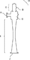
- FIG. 2 shows an example of the steam ejector (10).
- the number of stages of the steam ejector may be one stage when the compression ratio is small.
- the required drive steam volume increases rapidly as the compression ratio increases.
- an aspect of reducing consumption of driving steam can be given.
- the number of incidental facilities such as capacitors increases, it is not desirable to increase the number of stages excessively. Taking these into account, the number of stages of the steam ejector is suitably 1 to 4.
- the outer surface of the steam ejector is heated.
- the heating site is preferably the outer surface of the suction port (A) and the outer surface of the vacuum chamber (D), more preferably the outer surface of the diffuser (E) added thereto.
- the concentration of the easily polymerizable compound contained in the sucked gas becomes higher on the upstream side. Therefore, usually, the outer surface of at least the first stage steam ejector is heated, and more steam ejectors from the upstream side are used. It is preferable to heat the outer surface of the steam ejector, and it is more preferable to heat the outer surfaces of all the steam ejectors.
- the preferable temperature range by heating is based on actual results, and it is preferable that the outer surface temperature of the steam ejector is usually 50 ° C. or higher, preferably 60 ° C. or higher, more preferably 70 ° C. or higher.
- the outer surface temperature of the steam ejector means the outer surface temperature of the lowest temperature portion of the outer surfaces of the suction port, the vacuum chamber, and the diffuser of the steam ejector.
- the location where the temperature is measured does not include a location where the distance from the space inside the steam ejector exceeds 25 mm, such as a column welded to a joint portion with a flange portion or a support member.
- the temperature can be measured, for example, by inserting a thermometer from the gap or end of the installed heat source or using a non-contact type thermometer such as a radiation temperature system.
- the sucked gas expands in volume as the temperature rises and increases the load of the steam ejector.
- the outer surface temperature of the ejector is usually less than 150 ° C., preferably 140 ° C. or less, more preferably 130 ° C. or less.
- heating method For example, winding steam piping (steam trace), winding the heating wire of a heat-transfer heater, etc. are mentioned. At this time, it is preferable to wind a heating wire of a heat transfer heater because precise temperature control is possible, and it is more preferable to wind a steam trace because a heat source can be easily obtained and temperature control is easy.
- one steam trace or a heating wire of a ribbon-shaped heat transfer heater may be wound around the steam ejector, or several may be wound.
- the steam trace pipe wound around the steam ejector and the heating wire of the ribbon heat transfer heater may or may not be spaced from each other as shown in FIG. In short, it is only necessary that the outer surface of the steam ejector can be heated to a predetermined temperature.
- the outer surface of the steam ejector may be heated in advance before the operation period of the steam ejector. Further, it is preferable to continuously heat the outer surface during the operation period of the steam ejector, but even if the heating of the outer surface is temporarily interrupted for some reason, the effect of the present invention is not lost.
- the cold condenser at 16 ° C. was supplied to the vent condenser as a refrigerant, and the uncondensed components were led to the suction port of the first stage steam ejector.
- a steam ejector as shown in FIG. 2 was used as the steam ejector.
- the gas piping from the vent condenser to the steam ejector was kept warm with steam trace and heat insulating material. Air was supplied to the middle of the gas pipe with a control valve (CV) so that the top pressure of the distillation column was constant.
- the mixed exhaust gas from the steam ejector was cooled by cooling water at 28 ° C. and 16 ° C.
- the mixed exhaust gas from the steam ejector was cooled by cooling water at 28 ° C. with a heat exchanger, and the uncondensed components were led to the suction port of a liquid ring vacuum pump.
- the driving steam of the steam ejector was 1.2 MPaG in both the first and second stages.
- the external temperature of the first stage steam ejector suction port was confirmed by a radiation thermometer, and it was 40 to 46 ° C. This is apparently higher than the temperature of the non-condensed component in the vent condenser, and at least higher than the dew point of the suction gas.
- Example 1 Except for operating the distillation column while heating the outer surface of the suction port of the first and second stage steam ejectors, the outer surface of the vacuum section, and the outer surface of the diffuser using a steam trace as shown in FIG. was the same as in Comparative Example 1 above.
- the steam used for the steam trace was 0.3 MPaG.
- the outer surface temperature of the suction port of the steam ejector was 70 to 85 ° C.
- the steam for the trace was stopped for 2 days, the steam for the trace was stopped, and then the supply of the steam was restarted.
- no significant difference was confirmed before and after that. From the above, it has been clarified that heating the outer surface of the steam ejector is particularly effective in continuing operation for a long period of time, and heating can be stopped for a relatively short time.
Landscapes
- Chemical & Material Sciences (AREA)
- Organic Chemistry (AREA)
- Engineering & Computer Science (AREA)
- Chemical Kinetics & Catalysis (AREA)
- Crystallography & Structural Chemistry (AREA)
- Oil, Petroleum & Natural Gas (AREA)
- Physics & Mathematics (AREA)
- Fluid Mechanics (AREA)
- Mechanical Engineering (AREA)
- General Engineering & Computer Science (AREA)
- Organic Low-Molecular-Weight Compounds And Preparation Thereof (AREA)
- Vaporization, Distillation, Condensation, Sublimation, And Cold Traps (AREA)
Abstract
Description
また、前記スチームエジェクタの外面を50℃以上に加熱することが好ましい。
また、前記スチームエジェクタは多段であることも好ましく、前記スチームエジェクタの下流に液封式の真空ポンプが配置されることも好ましい。
また、前記スチームエジェクタの外面は、スチームトレースを用いて加熱することが好ましく、伝熱ヒーターを用いて加熱することも好ましい。
また、前記スチームエジェクタの外面を50℃以上に加熱することが好ましい。
また、前記スチームエジェクタは多段であることも好ましく、前記スチームエジェクタの下流に液封式の真空ポンプが配置されることも好ましい。
規則充填物として例えば、スルーザーパッキング(スルザーケムテック社製)、テクノパック(三冷テクノ社製)等のガーゼ型規則充填物、メラパック(スルザーケムテック社製)、テクノパック(三冷テクノ社製)、エムシーパック(三菱化学エンジニアリング社製)等のシート型規則充填物、フレキシグリッド(コークグリッチ社製)等のグリッド型規則充填物等が挙げられる。その他、金属線を束ねて編まれたグッドロールパッキング(トウトクエンジ社製)、金属線を垂直に多数配したスーパーHパック(ナガオカ社製)等が挙げられる。
リボイラ(II)として例えば、多管式熱交換器やスパイラル型熱交換器が挙げられる。薄膜式蒸発器をリボイラの代わりに、或いはリボイラと併用することも可能である。
用いられる重合防止剤として例えば、ハイドロキノンやメトキノンなどのフェノール化合物、2,2-ジブチルジチオカルバミン酸等のジアルキルジチオカルバミン酸の銅ないしマンガン錯体、4-ヒドロキシ-2,2,6,6-テトラメチルピリジルオキシド等のニトロキシルラジカル化合物、フェノチアジン等が挙げられる。同様の目的で、空気や窒素希釈された空気などの酸素含有気体も供給される。該酸素含有気体は、圧力計等の計装機器を塔内のプロセス流体から保護するためのパージガスとしても用いられる。
易重合性化合物のうち、アクリル酸であれば100℃以下が好ましく、より好ましくは90℃以下である。また、アクリル酸エステルの場合、その種類により沸点が大きく異なるため、同じ数値範囲では定められないが、上記同様、重合抑制の観点から、常圧下におけるアクリル酸類の沸点に対し、塔底温度が10~100℃低いことが好ましく、15~90℃低いことがより好ましい。
図2はスチームエジェクタ(10)の一例である。ベントコンデンサ(V)からの未凝縮成分(6)を吸引する吸引口(A)、駆動蒸気の供給口(B)、蒸気室(C)、真空室(D)、真空室(D)内の蒸気ノズル(図示無し)、ディフューザー(E)、そして未凝縮成分と蒸気の混合気体の出口(F)から成る。
多段のスチームエジェクタが用いられる場合、吸引される気体に含まれる易重合性化合物の濃度は上流側ほど高くなることから、通常少なくとも一段目のスチームエジェクタの外面を加熱し、上流からより多くスチームエジェクタの外面を加熱することが好ましく、全てのスチームエジェクタの外面を加熱することがより好ましい。
なお、上記スチームエジェクタの外面温度とは、スチームエジェクタの吸引口、真空室、およびディフューザーの各部位の外表面のうち、最も温度が低い部位の外表面温度を意味する。但し、該温度を測定する箇所として、フランジ部や支持部材との接合部に溶接された支柱など、スチームエジェクタ内部の空間からの距離が25mmを超える箇所については、これを含めない。該温度は、例えば、施工された加熱源の隙間や端部から温度計を挿入するか、放射温度系などの非接触型温度計を用いて測定することが出来る。
プロピレンの接触気相酸化により得られたアクリル酸含有ガスを溶媒で捕集し、該溶媒を蒸留分離して得られたアクリル酸濃度99%以上で、重合防止剤としてフェノチアジンとジブチルジチオカルバミン酸銅を含む粗アクリル酸を蒸留塔に供給した。蒸留塔はIMTPによる不規則充填塔を使用した。塔頂圧力を2.8kPa、塔頂温度を52℃、還流比を1.2で運転したところ、還流槽の液温度は28℃、塔底温度は72℃であった。塔頂コンデンサ並びに還流ラインに重合防止剤としてメトキノンを供給し、また、塔底より重合防止用に窒素希釈した空気を供給した。
比較例と同様にして、但しスチームエジェクタの駆動蒸気を1.0MPaGにて蒸留塔の運転を行った。スチームエジェクタ洗浄後にCV開度が低下するまでの時間は、3週間及び5週間であり、改善は得られなかった。
一段目と二段目のスチームエジェクタの吸引口の外面、真空部の外面、及びディフューザーの外面を、図3に示すように、スチームトレースを用いて加熱しながら蒸留塔の運転を行ったこと以外は、上記比較例1と同様にした。スチームトレースに用いた蒸気は0.3MPaGであった。スチームエジェクタの吸引口の外面温度は70~85℃であった。11ヶ月の運転継続において、明確なCV開度の低下は見られなかった。尚、運転を6ヶ月継続した時点で2日間、スチームトレースの配管はそのままに、トレース用の蒸気を停止し、次いで蒸気の供給を再開したが、その前後で有意差は確認されなかった。以上より、スチームエジェクタの外面を加熱することが特に長期間の運転継続において有効であると共に、比較的短時間の加熱停止は可能であることが明らかとなった。
2 塔底液
3 塔頂留出ガス
4 還流液
5、6、8 未凝縮成分
7 駆動蒸気
I 蒸留塔
II リボイラ
III、VII、VIIb コンデンサ
IV ドラム
V ベントコンデンサ
10、VI、VIb スチームエジェクタ
VIII、VIIIb 槽
IX 液封式真空ポンプ
A 吸引口
B 供給口
C 蒸気室
D 真空室
E ディフューザー
F 出口
G スチームトレース
Claims (14)
- プロパン、プロピレン又はアクロレインを原料とする気相接触酸化反応により得られたアクリル酸をスチームエジェクタにより減圧蒸留する工程を含むアクリル酸の製造方法であって、
該減圧蒸留工程が、該スチームエジェクタの外面を加熱する工程を含む、アクリル酸の製造方法。 - 前記スチームエジェクタの外面をスチームトレースを用いて加熱する、請求項1に記載の方法。
- 前記スチームエジェクタの外面を伝熱ヒーターを用いて加熱する、請求項1に記載の方法。
- 前記スチームエジェクタの外面を50℃以上に加熱する、請求項1~3のいずれか1項に記載の方法。
- 前記スチームエジェクタが多段である、請求項1~4のいずれか1項に記載の方法。
- 前記スチームエジェクタの下流に液封式の真空ポンプが配置される、請求項1~5のいずれか1項に記載の方法。
- スチームエジェクタを用いた易重合性化合物の減圧蒸留の方法であって、該スチームエジェクタの外面を加熱する工程を含む、方法。
- 前記易重合性化合物がアクリル酸又はアクリル酸エステルである、請求項7に記載の方法。
- 前記易重合性化合物が、プロパン、プロピレン又はアクロレインを原料とする気相接触酸化反応により得られたアクリル酸である、請求項8に記載の方法。
- 前記スチームエジェクタの外面をスチームトレースを用いて加熱する、請求項7~9のいずれか1項に記載の方法。
- 前記スチームエジェクタの外面を伝熱ヒーターを用いて加熱する、請求項7~9のいずれか1項に記載の方法。
- 前記スチームエジェクタの外面を50℃以上に加熱する、請求項7~11のいずれか1項に記載の方法。
- 前記スチームエジェクタが多段である、請求項7~12のいずれか1項に記載の方法。
- 前記スチームエジェクタの下流に液封式の真空ポンプが配置される、請求項7~13のいずれか1項に記載の方法。
Priority Applications (4)
| Application Number | Priority Date | Filing Date | Title |
|---|---|---|---|
| EP14857447.8A EP3064485B2 (en) | 2013-10-29 | 2014-10-28 | Vacuum distillation method for easily polymerizable compound and method for producing acrylic acid |
| CN201480059285.4A CN105683145B (zh) | 2013-10-29 | 2014-10-28 | 易聚合性化合物的减压蒸馏方法及丙烯酸的制造方法 |
| BR112016009448-4A BR112016009448B1 (pt) | 2013-10-29 | 2014-10-28 | Método para a produção de ácido acrílico |
| US15/134,980 US9738586B2 (en) | 2013-10-29 | 2016-04-21 | Vacuum distillation method for easily polymerizable compound and method for producing acrylic acid |
Applications Claiming Priority (2)
| Application Number | Priority Date | Filing Date | Title |
|---|---|---|---|
| JP2013224082 | 2013-10-29 | ||
| JP2013-224082 | 2013-10-29 |
Related Child Applications (1)
| Application Number | Title | Priority Date | Filing Date |
|---|---|---|---|
| US15/134,980 Continuation US9738586B2 (en) | 2013-10-29 | 2016-04-21 | Vacuum distillation method for easily polymerizable compound and method for producing acrylic acid |
Publications (1)
| Publication Number | Publication Date |
|---|---|
| WO2015064563A1 true WO2015064563A1 (ja) | 2015-05-07 |
Family
ID=53004165
Family Applications (1)
| Application Number | Title | Priority Date | Filing Date |
|---|---|---|---|
| PCT/JP2014/078603 WO2015064563A1 (ja) | 2013-10-29 | 2014-10-28 | 易重合性化合物の減圧蒸留の方法およびアクリル酸の製造方法 |
Country Status (6)
| Country | Link |
|---|---|
| US (1) | US9738586B2 (ja) |
| EP (1) | EP3064485B2 (ja) |
| JP (3) | JP2015110551A (ja) |
| CN (1) | CN105683145B (ja) |
| BR (1) | BR112016009448B1 (ja) |
| WO (1) | WO2015064563A1 (ja) |
Families Citing this family (2)
| Publication number | Priority date | Publication date | Assignee | Title |
|---|---|---|---|---|
| DE202015106097U1 (de) * | 2015-11-11 | 2016-02-01 | Holger Blum | Fördereinrichtung für eine Vakuumdestillationsanlage |
| JP7147567B2 (ja) * | 2018-01-19 | 2022-10-05 | 三菱ケミカル株式会社 | (メタ)アクリル酸又はそのエステルの製造方法 |
Citations (7)
| Publication number | Priority date | Publication date | Assignee | Title |
|---|---|---|---|---|
| JPH01105000A (ja) * | 1987-10-15 | 1989-04-21 | Hitachi Ltd | 真空エゼクタ装置 |
| JP2000256221A (ja) * | 1999-03-04 | 2000-09-19 | Mitsubishi Chemicals Corp | 易重合性化合物の精製方法 |
| JP2000344711A (ja) | 1999-06-03 | 2000-12-12 | Nippon Shokubai Co Ltd | 易重合性化合物の精製方法 |
| WO2003018162A1 (fr) * | 2001-08-22 | 2003-03-06 | Mitsubishi Chemical Corporation | Materiel de distillation de compose du type en lase de polymerisation |
| JP2005289927A (ja) | 2004-04-01 | 2005-10-20 | Mitsubishi Chemicals Corp | (メタ)アクリル酸誘導体の製造方法 |
| JP2007217401A (ja) * | 2006-01-20 | 2007-08-30 | Nippon Shokubai Co Ltd | (メタ)アクリル酸の製造方法 |
| JP2007255805A (ja) * | 2006-03-24 | 2007-10-04 | Chugoku Electric Power Co Inc:The | 真空ポンプ装置用ヒータの配線構造 |
Family Cites Families (21)
| Publication number | Priority date | Publication date | Assignee | Title |
|---|---|---|---|---|
| JPS4833057Y1 (ja) * | 1970-07-01 | 1973-10-08 | ||
| US3702346A (en) * | 1971-06-30 | 1972-11-07 | Universal Oil Prod Co | Conversion of ethylbenzene to styrene |
| JPH10204030A (ja) * | 1997-01-24 | 1998-08-04 | Toagosei Co Ltd | (メタ)アクリル酸エステルの精製方法及び製造方法並びにその製造装置 |
| JP2000344688A (ja) * | 1999-06-04 | 2000-12-12 | Mitsubishi Chemicals Corp | 易重合性化合物の精製方法 |
| JP3948855B2 (ja) | 1999-06-10 | 2007-07-25 | 株式会社日本触媒 | (メタ)アクリル酸の製造方法 |
| JP2001131116A (ja) | 1999-11-08 | 2001-05-15 | Nippon Shokubai Co Ltd | 易重合性物質含有液の蒸留方法 |
| US6739288B1 (en) * | 2000-01-14 | 2004-05-25 | Tvl Co., Ltd. | Steam heating device |
| JP2001213839A (ja) | 2000-02-03 | 2001-08-07 | Nippon Shokubai Co Ltd | (メタ)アクリル酸の製造方法 |
| JP3875471B2 (ja) * | 2000-08-28 | 2007-01-31 | 株式会社日立製作所 | 復水器真空ポンプシステム |
| JP4074455B2 (ja) * | 2001-11-27 | 2008-04-09 | 三菱化学株式会社 | (メタ)アクリル酸の製造方法 |
| JP2003073327A (ja) * | 2001-09-03 | 2003-03-12 | Nippon Shokubai Co Ltd | 有機酸の製造方法 |
| JP2003103105A (ja) * | 2001-09-28 | 2003-04-08 | Sumitomo Chem Co Ltd | 易重合性物質の蒸留方法およびこれに使用する蒸留装置 |
| JP4783530B2 (ja) * | 2001-09-28 | 2011-09-28 | 住友化学株式会社 | 易重合性物質の蒸留方法およびこれに使用する蒸留装置 |
| JP4095471B2 (ja) | 2003-02-28 | 2008-06-04 | 株式会社日本触媒 | 易重合性物質の蒸留方法 |
| JP2004269417A (ja) * | 2003-03-07 | 2004-09-30 | Mitsubishi Rayon Co Ltd | (メタ)アクリル酸エステルの製造方法 |
| JP2007162975A (ja) * | 2005-12-09 | 2007-06-28 | Miura Co Ltd | 食品機械 |
| KR100999428B1 (ko) | 2006-01-20 | 2010-12-09 | 니폰 쇼쿠바이 컴파니 리미티드 | (메타)아크릴산의 제조 방법 |
| JP5097533B2 (ja) | 2007-12-21 | 2012-12-12 | 三菱レイヨン株式会社 | 易重合性物質取扱装置 |
| JP2009249314A (ja) † | 2008-04-03 | 2009-10-29 | Mitsubishi Rayon Co Ltd | (メタ)アクリル酸ヒドロキシアルキルエステルの製造装置 |
| CN104174180B (zh) * | 2009-03-19 | 2017-01-04 | Lg化学株式会社 | 用于制备高纯度丙烯酸的分隔壁蒸馏塔和使用该分隔壁蒸馏塔的分馏方法 |
| JP5513279B2 (ja) * | 2010-06-24 | 2014-06-04 | 日本エゼクターエンジニアリング株式会社 | 製鋼用二次精錬における真空脱ガス用の不純物および排ガス処理装置 |
-
2014
- 2014-10-28 BR BR112016009448-4A patent/BR112016009448B1/pt active IP Right Grant
- 2014-10-28 JP JP2014219226A patent/JP2015110551A/ja active Pending
- 2014-10-28 WO PCT/JP2014/078603 patent/WO2015064563A1/ja active Application Filing
- 2014-10-28 CN CN201480059285.4A patent/CN105683145B/zh active Active
- 2014-10-28 EP EP14857447.8A patent/EP3064485B2/en active Active
-
2016
- 2016-04-21 US US15/134,980 patent/US9738586B2/en active Active
-
2018
- 2018-10-22 JP JP2018198260A patent/JP6777131B2/ja active Active
-
2020
- 2020-10-05 JP JP2020168277A patent/JP2020203957A/ja not_active Withdrawn
Patent Citations (8)
| Publication number | Priority date | Publication date | Assignee | Title |
|---|---|---|---|---|
| JPH01105000A (ja) * | 1987-10-15 | 1989-04-21 | Hitachi Ltd | 真空エゼクタ装置 |
| JP2000256221A (ja) * | 1999-03-04 | 2000-09-19 | Mitsubishi Chemicals Corp | 易重合性化合物の精製方法 |
| JP2000344711A (ja) | 1999-06-03 | 2000-12-12 | Nippon Shokubai Co Ltd | 易重合性化合物の精製方法 |
| WO2003018162A1 (fr) * | 2001-08-22 | 2003-03-06 | Mitsubishi Chemical Corporation | Materiel de distillation de compose du type en lase de polymerisation |
| JP2005289927A (ja) | 2004-04-01 | 2005-10-20 | Mitsubishi Chemicals Corp | (メタ)アクリル酸誘導体の製造方法 |
| WO2005100295A1 (ja) * | 2004-04-01 | 2005-10-27 | Mitsubishi Chemical Corporation | (メタ)アクリル酸誘導体の製造方法 |
| JP2007217401A (ja) * | 2006-01-20 | 2007-08-30 | Nippon Shokubai Co Ltd | (メタ)アクリル酸の製造方法 |
| JP2007255805A (ja) * | 2006-03-24 | 2007-10-04 | Chugoku Electric Power Co Inc:The | 真空ポンプ装置用ヒータの配線構造 |
Non-Patent Citations (1)
| Title |
|---|
| See also references of EP3064485A4 |
Also Published As
| Publication number | Publication date |
|---|---|
| BR112016009448A2 (pt) | 2017-08-01 |
| EP3064485B1 (en) | 2017-11-29 |
| JP2015110551A (ja) | 2015-06-18 |
| JP2019014750A (ja) | 2019-01-31 |
| US20160237017A1 (en) | 2016-08-18 |
| EP3064485A1 (en) | 2016-09-07 |
| CN105683145B (zh) | 2017-11-14 |
| BR112016009448B1 (pt) | 2021-07-13 |
| US9738586B2 (en) | 2017-08-22 |
| CN105683145A (zh) | 2016-06-15 |
| EP3064485A4 (en) | 2016-11-09 |
| JP6777131B2 (ja) | 2020-10-28 |
| JP2020203957A (ja) | 2020-12-24 |
| EP3064485B2 (en) | 2021-02-24 |
Similar Documents
| Publication | Publication Date | Title |
|---|---|---|
| US7566804B2 (en) | Process for preparing acrylic acid | |
| US7368602B2 (en) | Process for producing (meth) acrylic acid | |
| JP6716597B2 (ja) | (メタ)アクリル酸の改良された製造方法 | |
| JP5368673B2 (ja) | (メタ)アクリル酸の製造方法 | |
| JP6290460B2 (ja) | アクリル酸の製造方法 | |
| JP2020203957A (ja) | 易重合性化合物の減圧蒸留の方法およびアクリル酸の製造方法 | |
| JP3971974B2 (ja) | (メタ)アクリル酸類の製造方法 | |
| US7476299B2 (en) | Vessel for easily polymerizable compound | |
| US8044238B2 (en) | Method for production of purified (meth)acrylic acid | |
| WO2019142862A1 (ja) | (メタ)アクリル酸又はそのエステルの製造方法 | |
| EP1459794A2 (en) | Apparatus and process for purification of acrylic acid family | |
| JP2018115155A (ja) | アクリル酸の製造方法 | |
| WO2019189259A1 (ja) | 不飽和カルボン酸エステルの製造方法 | |
| JP4437930B2 (ja) | アクリル酸類の蒸留精製方法 | |
| JP2010163383A (ja) | アクリル酸の精製方法 | |
| JP2023050471A (ja) | アクリル酸製造プロセス廃水の回収・再利用方法 | |
| JP2003267917A (ja) | 蒸留塔の運転停止方法 | |
| JP2005230584A (ja) | 易重合性化合物用の塔設備 | |
| JP2011098992A (ja) | 易重合性物質含有液の蒸留方法 | |
| JP2008266159A (ja) | アクリル酸ブチルの精製方法 |
Legal Events
| Date | Code | Title | Description |
|---|---|---|---|
| 121 | Ep: the epo has been informed by wipo that ep was designated in this application |
Ref document number: 14857447 Country of ref document: EP Kind code of ref document: A1 |
|
| WWE | Wipo information: entry into national phase |
Ref document number: 139550140003001154 Country of ref document: IR |
|
| WWE | Wipo information: entry into national phase |
Ref document number: 122020021543 Country of ref document: BR |
|
| NENP | Non-entry into the national phase |
Ref country code: DE |
|
| REG | Reference to national code |
Ref country code: BR Ref legal event code: B01A Ref document number: 112016009448 Country of ref document: BR |
|
| REEP | Request for entry into the european phase |
Ref document number: 2014857447 Country of ref document: EP |
|
| WWE | Wipo information: entry into national phase |
Ref document number: 2014857447 Country of ref document: EP |
|
| ENP | Entry into the national phase |
Ref document number: 112016009448 Country of ref document: BR Kind code of ref document: A2 Effective date: 20160428 |