WO2015064544A1 - アシストグリップ - Google Patents
アシストグリップ Download PDFInfo
- Publication number
- WO2015064544A1 WO2015064544A1 PCT/JP2014/078515 JP2014078515W WO2015064544A1 WO 2015064544 A1 WO2015064544 A1 WO 2015064544A1 JP 2014078515 W JP2014078515 W JP 2014078515W WO 2015064544 A1 WO2015064544 A1 WO 2015064544A1
- Authority
- WO
- WIPO (PCT)
- Prior art keywords
- pair
- assist grip
- groove
- portions
- rotating shaft
- Prior art date
Links
Images


Classifications
-
- B—PERFORMING OPERATIONS; TRANSPORTING
- B60—VEHICLES IN GENERAL
- B60N—SEATS SPECIALLY ADAPTED FOR VEHICLES; VEHICLE PASSENGER ACCOMMODATION NOT OTHERWISE PROVIDED FOR
- B60N3/00—Arrangements or adaptations of other passenger fittings, not otherwise provided for
- B60N3/02—Arrangements or adaptations of other passenger fittings, not otherwise provided for of hand grips or straps
- B60N3/026—Arrangements or adaptations of other passenger fittings, not otherwise provided for of hand grips or straps characterised by the fixing means
-
- B—PERFORMING OPERATIONS; TRANSPORTING
- B60—VEHICLES IN GENERAL
- B60N—SEATS SPECIALLY ADAPTED FOR VEHICLES; VEHICLE PASSENGER ACCOMMODATION NOT OTHERWISE PROVIDED FOR
- B60N3/00—Arrangements or adaptations of other passenger fittings, not otherwise provided for
- B60N3/04—Arrangements or adaptations of other passenger fittings, not otherwise provided for of floor mats or carpets
-
- B—PERFORMING OPERATIONS; TRANSPORTING
- B60—VEHICLES IN GENERAL
- B60N—SEATS SPECIALLY ADAPTED FOR VEHICLES; VEHICLE PASSENGER ACCOMMODATION NOT OTHERWISE PROVIDED FOR
- B60N3/00—Arrangements or adaptations of other passenger fittings, not otherwise provided for
- B60N3/02—Arrangements or adaptations of other passenger fittings, not otherwise provided for of hand grips or straps
- B60N3/023—Arrangements or adaptations of other passenger fittings, not otherwise provided for of hand grips or straps movable
Definitions
- the present invention relates to an assist grip that is provided in a passenger compartment of an automobile and is gripped when an occupant gets on and off, shakes, and the like, and particularly relates to a technique that can be easily attached and detached and can be reliably fixed.
- the heel assist grip is provided in the passenger compartment of the automobile so that the passenger can easily enter and exit from the passenger compartment of the automobile. By grasping the assist grip, it is possible to assist itself while entering or leaving the passenger compartment or sitting on the seat.
- the assist grip is a component that rotates from the storage position to the open position, and similarly from the open position to the storage position. In the storage position, the assist grip can be detached from the position on the passenger side (see, for example, Patent Document 1).
- the heel assist grip has been assembled by providing recesses at both ends in the longitudinal direction of the grip body, and inserting hinge members attached to the wall surface of the passenger compartment into the recesses.
- the hinge member is provided with a pair of upright portions, and a rotation shaft provided outside the upright portion is inserted into the grip bearing concave portion by a recess groove in the concave portion of the grip, and a damper is provided inside the upright portion. It is provided to prevent it from coming off.
- the above-described assist grip has the following problems. That is, in order to insert the pivot shaft of the hinge member from the saddle groove into the grip bearing recess, it is necessary to bend the standing portion, and the insertion work is difficult. In addition, there is a possibility that the rigidity may be insufficient, such as making the standing portion thin for bending. Furthermore, when no damper is provided, a separate part may be required to prevent the damper from coming off.
- an object of the present invention is to provide an assist grip that allows easy insertion of a hinge member into a grip body and can be reliably fixed.
- the present invention provides an assist grip attached to a passenger compartment of an automobile, a pair of recesses formed at both ends in the longitudinal direction, and the longitudinal portions of the respective peripheral walls of the recesses.
- a grip body having a pair of groove portions formed in portions facing each other in a direction, a pair of standing portions accommodated in the recess and spaced apart from each other, and projecting to both outer sides of the standing portions,
- a hinge having a pair of pivot shafts formed so as to be able to be inserted into the groove portions, and a bearing provided at one end of the pair of groove portions, and one end of the pair of pivot shafts inserted into a terminal portion of the one groove portion.
- a concave portion and a stopper member that prevents the rotating shaft from being inserted into the bearing concave portion where one end of the rotating shaft is inserted are provided.
- FIG. 4 is a cross-sectional view of the assist grip taken along line AA in FIG. 3 and viewed in the direction of the arrow.
- FIG. 4 is a cross-sectional view of the assist grip taken along line BB in FIG. 3 and viewed in the direction of the arrow.
- FIG. 4 is a cross-sectional view of the assist grip taken along line CC in FIG. 3 and viewed in the direction of the arrow.
- It is a front view which shows one groove part in the recessed part of the assist grip.
- It is a front view which shows the other groove part in the recessed part of the assist grip.
- It is a perspective view which shows the assembly method of the assist grip schematically.
- FIG. 1 is a perspective view showing an assist grip 10 according to an embodiment of the present invention
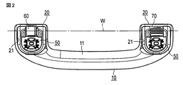
- FIG. 2 is a plan view showing the assist grip 10
- FIG. 3 is a side view showing the assist grip 10
- FIG. FIG. 5 is a cross-sectional view of the assist grip 10 taken along the line AA in FIG. 3 and viewed in the direction of the arrow
- FIG. 5 is a cross-sectional view of the assist grip 10 cut along the line BB in FIG. 6
- FIG. 7 is a front view showing one groove portion in the recess of the assist grip 10
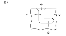
- FIG. 3 is a front view showing the other groove in the recess of the grip 10.
- P indicates a passenger compartment
- W indicates a longitudinal direction.
- the assist grip 10 is provided in the passenger compartment P of the automobile so that the passenger can easily enter and exit from the passenger compartment P of the automobile. By grasping the assist grip 10, it is possible to assist itself while entering or leaving the passenger compartment 10 or sitting on the seat. As shown by an arrow Q in FIG. 1, the assist grip 10 can be rotated from the storage position to the open position, and similarly from the open position to the storage position. In the storage position, the assist grip 10 can be detached from the position on the passenger side.
- the assist grip 10 has a rod-shaped handle main body 11 that is easily grasped by an occupant.
- the handle main body 11 includes a pair of attachment portions 20 at both ends in the longitudinal direction W thereof.
- One mounting portion 20 is formed with a recess 21 (see FIGS.
- a pair of groove portions 30 and 40 are provided on the inner wall (peripheral wall) of the recess 21 at positions facing each other in the longitudinal direction W (see FIG. (See FIGS. 7 and 8).
- the pair of groove portions 30 and 40 have different structures as will be described later, and the other attachment portion 20 also has a pair of groove portions 30 and 40 having the same structure on the same side in the longitudinal direction W.
- a hinge 50 is detachably provided in the recess 21.
- the groove portion 30 includes a first groove 31 extending in the insertion direction, a second groove 32 bent at a right angle from the end of the first groove 31, and a bearing provided at the end of the second groove 32. And a recess 33.
- channel 32 are formed comparatively shallow, and guide the round boss
- the bearing recess 33 is formed deeper than the first groove 31 and the second groove 32. The bearing recess 33 supports a round boss portion 52a described later.
- the groove portion 40 includes a first groove 41 extending in the insertion direction and a second groove 42 that bends at right angles from the terminal end of the first groove 41.
- the first groove 41 and the second groove 42 are formed deeper than the first groove 31 and the second groove 32, and guide the round boss portion 53a.
- the second groove 42 supports a round boss portion 53a described later.
- the hinge 50 includes a hinge main body 51 projecting and retracting from the recess 21 by rotation, plate-like standing portions 52 and 53 provided at both ends in the longitudinal direction W of the hinge main body 51, and the standing portions 52 and 53. Round bosses (rotating shafts) 52a and 53a projecting in the longitudinal direction W, and an engaging part 54 attached to the passenger compartment P.
- a cylindrical damper 60 is arranged between the standing portions 52 and 53 coaxially with the round boss portions 52a and 53a.
- the damper 60 includes an inner cylinder part 61 fixed to the standing parts 52 and 53 and an outer cylinder part 62 disposed on the outer periphery of the inner cylinder part 61 and rotating viscously.
- the damper 60 has a desirable braking effect for controlling the repulsion speed and repulsion force in the rotation direction Q of the assist grip 10.
- a coil spring 70 is disposed in the other recess 21.
- the coil spring 70 biases the assist grip 10 in a direction to return it to the storage position.
- a cover 80 is detachably provided on the heel hinge 50 (see FIG. 9).
- the cover unit 80 includes a cover body 81 that is attached to the hinge body 51.
- Wall bodies 82 and 83 are provided in the longitudinal direction W of the cover main body 81, and a stopper member 84 extending from the one wall body 82 toward the round boss portion 53a is provided.
- the tip of the stopper member 84 is provided with a semi-annular (substantially U-shaped) engaging portion 84a along the outer periphery of the round boss portions 52a and 53a.
- the engaging portion 84a is fixed by engaging with the outer periphery of the round boss portion 53a, is sandwiched between the standing portion 53 and the inner wall surface of the concave portion 21, and restricts the movement of the hinge body 51 in the longitudinal direction W. . Therefore, it is possible to prevent the round boss portions 52a and 53a from coming out of the groove portions 30 and 40.
- FIG. 9 is a perspective view schematically showing a method for assembling the assist grip 10.
- the damper 60 is disposed between the standing portions 52 and 53.
- the round boss portions 52a and 53a of the hinge 50 are inserted into the first groove 31 of the groove portion 30 and the first groove 41 of the groove portion 40, respectively. Since the groove part 40 has sufficient depth, it can insert easily, without making the standing parts 52 and 53 bend.
- the round boss portions 52a and 53a of the hinge 50 are moved along the second groove 32 and the second groove 42, and are moved to their respective terminal portions. Then, the round boss portion 52 a of the hinge 50 is moved in the longitudinal direction W so as to drop into the bearing recess 33. Thereby, the outer peripheral part of the round boss part 53a of the hinge 50 is exposed.
- the rib 62 a provided on the outer periphery of the outer cylindrical portion 62 of the damper 60 is engaged with the inner wall surface of the recess 21.
- the engaging portion 84a of the stopper member 84 is engaged with the outer peripheral portion of the round boss portion 53a, and the cover body 81 is attached as it is and fixed using a metal clip or the like.
- the hinge 50 is attached to the other recess 21 in the same manner.
- the coil spring 70 has one end attached to one of the standing portions 52 and 53 and the other end attached to the inner wall surface of the recess 21.
- the insertion work can be easily performed without bending the standing portions 52 and 53, and moreover, the stopper member 84 can be securely fixed. Assembly work is easy. Moreover, durability can be maintained without reducing the rigidity of the standing portions 52 and 53.
- the groove part depth of the groove part 30 provided with the bearing recessed part 33 is shallow and the groove part depth of the groove part 40 is deep, and the rotary boss part 53a exists in the groove part 40 in the state where the rotating shaft is inserted, the groove parts on both sides are provided. A high holding strength can be obtained by pivoting at 30 and 40.
- the collar stopper member 84 is formed integrally with the cover portion 80 for the hinge, the number of parts can be reduced, and the work process and product cost can be reduced.
- the hinge 50 and the cover member 80 can have the same shape, and the product cost can be reduced.
- the round boss portions 52a and 53a are not integrally formed of the same material as the standing portions 52 and 53, but a part that penetrates the standing portions 52 and 53, such as a metal shaft, may be used as the rotation shaft. Good. Further, instead of the coil spring 70, the assist grip 10 may be biased using a different type of elastic body such as a leaf spring.
Landscapes
- Engineering & Computer Science (AREA)
- Transportation (AREA)
- Mechanical Engineering (AREA)
- Passenger Equipment (AREA)
Abstract
Description
アシストグリップ10は、乗員が掴み易い棒状のハンドル本体11を有している。ハンドル本体11は、その長手方向Wの両端に一対の取付部20を備えている。一方の取付部20には、凹部21が形成され(図5,6参照)、凹部21の内壁(周壁)には長手方向Wにおいて対向する位置に一対の溝部30,40が設けられている(図7,8参照)。これら一対の溝部30,40は後述するように異なる構造であり、他方の取付部20においても長手方向Wにおける同じ側に同じ構造の一対の溝部30,40が配置されている。凹部21にはヒンジ50が着脱可能に設けられている。
なお、2013年10月28日に出願された日本特許出願第2013-223721号の明細書、特許請求の範囲、図面及び要約書の全内容をここに引用し、本発明の明細書の開示として、取り入れるものである。
Claims (6)
- 自動車の車室内に取り付けられるアシストグリップにおいて、
長手方向の両端に形成された一対の凹部、及び、これら凹部のそれぞれの周壁における前記長手方向で対向する部分に形成された一対の溝部を有するグリップ本体と、
前記凹部に収容され、所定の間隔を隔てた一対の立設部と、これら立設部の両外側に突出し、前記一対の溝部にそれぞれ挿通可能に形成された一対の回動軸を有するヒンジと、
前記一対の溝部の一方に設けられ、この一方の溝部の終端部に前記一対の回動軸の一端が挿入される軸受凹部と、
前記軸受凹部に前記回動軸の一端が挿入された回転軸挿入状態から抜けるのを防止するストッパ部材とを備えていることを特徴とするアシストグリップ。 - 前記一対の溝部の、前記軸受凹部が設けてある側の一方側の溝部深さが浅く、他方側の溝部深さが深くなっており、前記回転軸挿入状態で前記回転軸の他端側が他方の溝部内にあることを特徴とする請求項1に記載のアシストグリップ。
- 前記ストッパ部材は、前記凹部の周壁と前記立設部の間に挿入される突設部がストッパ部となり、前記ヒンジに対するカバー部と一体に形成されていることを特徴とする請求項1に記載のアシストグリップ。
- 前記ストッパ部材は、略U字形状で、前記回動軸の外周面に係合することを特徴とする請求項3に記載のアシストグリップ。
- 前記回動軸は前記立設部から突出させた丸ボス形状であることを特徴とする請求項1~4のいずれか1に記載のアシストグリップ。
- 前記一対の溝部のうち、溝部深さが深い溝部は、前記長手方向における前記一対の凹部の同じ側に設けられていることを特徴とする請求項2に記載のアシストグリップ。
Priority Applications (4)
| Application Number | Priority Date | Filing Date | Title |
|---|---|---|---|
| CN201480058722.0A CN105682988B (zh) | 2013-10-28 | 2014-10-27 | 辅助把手 |
| MX2016005579A MX2016005579A (es) | 2013-10-28 | 2014-10-27 | Agarradera auxiliar. |
| EP14858330.5A EP3064395B1 (en) | 2013-10-28 | 2014-10-27 | Assist grip |
| US15/032,887 US9840177B2 (en) | 2013-10-28 | 2014-10-27 | Assist grip |
Applications Claiming Priority (2)
| Application Number | Priority Date | Filing Date | Title |
|---|---|---|---|
| JP2013-223721 | 2013-10-28 | ||
| JP2013223721A JP6076232B2 (ja) | 2013-10-28 | 2013-10-28 | アシストグリップ |
Publications (1)
| Publication Number | Publication Date |
|---|---|
| WO2015064544A1 true WO2015064544A1 (ja) | 2015-05-07 |
Family
ID=53004147
Family Applications (1)
| Application Number | Title | Priority Date | Filing Date |
|---|---|---|---|
| PCT/JP2014/078515 WO2015064544A1 (ja) | 2013-10-28 | 2014-10-27 | アシストグリップ |
Country Status (7)
| Country | Link |
|---|---|
| US (1) | US9840177B2 (ja) |
| EP (1) | EP3064395B1 (ja) |
| JP (1) | JP6076232B2 (ja) |
| KR (1) | KR101611740B1 (ja) |
| CN (1) | CN105682988B (ja) |
| MX (1) | MX2016005579A (ja) |
| WO (1) | WO2015064544A1 (ja) |
Families Citing this family (8)
| Publication number | Priority date | Publication date | Assignee | Title |
|---|---|---|---|---|
| JP6341873B2 (ja) | 2015-03-03 | 2018-06-13 | 株式会社ニフコ | 回動機構 |
| JP6352859B2 (ja) * | 2015-06-18 | 2018-07-04 | 株式会社ニフコ | アシストグリップ |
| US10248008B2 (en) * | 2016-01-14 | 2019-04-02 | Avigilon Corporation | Removable hinge |
| WO2017131851A1 (en) * | 2016-01-29 | 2017-08-03 | Illinois Tool Works Inc. | Systems and methods for securing an assist grip assembly to a component of a vehicle |
| US10040384B2 (en) * | 2016-12-29 | 2018-08-07 | GM Global Technology Operations LLC | Twist-lock articulating assist mechanism |
| JP2018197052A (ja) | 2017-05-23 | 2018-12-13 | 豊和化成株式会社 | アシストグリップ |
| JP7050706B2 (ja) * | 2019-03-04 | 2022-04-08 | 株式会社ニフコ | アシストグリップ |
| JP7441421B2 (ja) * | 2020-03-25 | 2024-03-01 | いすゞ自動車株式会社 | 車両のアームレスト取付構造 |
Citations (3)
| Publication number | Priority date | Publication date | Assignee | Title |
|---|---|---|---|---|
| JP2005138823A (ja) | 2003-11-03 | 2005-06-02 | Illinois Tool Works Inc <Itw> | 補助グリップハンドル用ピン無しダンパー組立て体 |
| US20120222360A1 (en) * | 2011-03-01 | 2012-09-06 | Ford Global Technologies, Llc | Collapsible door trim pull handle |
| JP2013023073A (ja) * | 2011-07-21 | 2013-02-04 | Toyoda Gosei Co Ltd | アシストグリップ |
Family Cites Families (19)
| Publication number | Priority date | Publication date | Assignee | Title |
|---|---|---|---|---|
| DE29712357U1 (de) * | 1997-07-12 | 1997-09-11 | Utescheny Endos Gmbh | Haltegriff für Fahrzeuginnenräume |
| JP2002052970A (ja) * | 2000-08-10 | 2002-02-19 | Nifco Inc | 回転体の制動構造、及びその回転体の制動構造を備えたアシストグリップ |
| JP2003276492A (ja) * | 2002-03-22 | 2003-09-30 | Nishikawa Kasei Co Ltd | 格納式アシストグリップ |
| JP2004066893A (ja) * | 2002-08-02 | 2004-03-04 | Nishikawa Kasei Co Ltd | 格納式アシストグリップ |
| DE20310944U1 (de) | 2003-07-16 | 2003-12-04 | Trw Automotive Electronics & Components Gmbh & Co.Kg | Lager für einen Fahrzeug-Haltegriff sowie Haltegriff |
| US7617571B2 (en) * | 2006-10-30 | 2009-11-17 | Illinois Tool Works Inc. | Pin-less assist grip handle assembly |
| JP5204628B2 (ja) * | 2008-11-12 | 2013-06-05 | 豊和化成株式会社 | アシストグリップ |
| JP5481120B2 (ja) * | 2009-07-22 | 2014-04-23 | 豊和化成株式会社 | アシストグリップ |
| JP5465978B2 (ja) * | 2009-10-19 | 2014-04-09 | 豊和化成株式会社 | アシストグリップ |
| JP5330965B2 (ja) * | 2009-11-18 | 2013-10-30 | 株式会社ニフコ | 回動体の制動構造 |
| JP2011235825A (ja) * | 2010-05-12 | 2011-11-24 | Toyoda Gosei Co Ltd | アシストグリップ |
| JP4774464B1 (ja) * | 2010-05-12 | 2011-09-14 | 豊田合成株式会社 | アシストグリップ |
| JP5436325B2 (ja) * | 2010-05-12 | 2014-03-05 | 豊田合成株式会社 | アシストグリップ |
| JP2012250548A (ja) * | 2011-05-31 | 2012-12-20 | Howa Kasei Kk | アシストグリップ |
| CN202200882U (zh) * | 2011-08-31 | 2012-04-25 | 常州市瑞悦车业有限公司 | 带阻尼的车内拉手 |
| JP5847556B2 (ja) * | 2011-11-18 | 2016-01-27 | 株式会社イノアックコーポレーション | アシストグリップ |
| JP2015058836A (ja) * | 2013-09-19 | 2015-03-30 | 豊和化成株式会社 | アシストグリップ |
| JP6262488B2 (ja) * | 2013-10-10 | 2018-01-17 | 株式会社パイオラックス | ダンパーおよびそれを備えるハンドル装置 |
| KR101449344B1 (ko) * | 2013-11-11 | 2014-10-08 | 주식회사 니프코코리아 | 자동차용 어시스트 핸들 |
-
2013
- 2013-10-28 JP JP2013223721A patent/JP6076232B2/ja active Active
-
2014
- 2014-10-20 KR KR1020140141677A patent/KR101611740B1/ko active IP Right Grant
- 2014-10-27 EP EP14858330.5A patent/EP3064395B1/en active Active
- 2014-10-27 WO PCT/JP2014/078515 patent/WO2015064544A1/ja active Application Filing
- 2014-10-27 MX MX2016005579A patent/MX2016005579A/es active IP Right Grant
- 2014-10-27 CN CN201480058722.0A patent/CN105682988B/zh active Active
- 2014-10-27 US US15/032,887 patent/US9840177B2/en active Active
Patent Citations (3)
| Publication number | Priority date | Publication date | Assignee | Title |
|---|---|---|---|---|
| JP2005138823A (ja) | 2003-11-03 | 2005-06-02 | Illinois Tool Works Inc <Itw> | 補助グリップハンドル用ピン無しダンパー組立て体 |
| US20120222360A1 (en) * | 2011-03-01 | 2012-09-06 | Ford Global Technologies, Llc | Collapsible door trim pull handle |
| JP2013023073A (ja) * | 2011-07-21 | 2013-02-04 | Toyoda Gosei Co Ltd | アシストグリップ |
Non-Patent Citations (1)
| Title |
|---|
| See also references of EP3064395A4 |
Also Published As
| Publication number | Publication date |
|---|---|
| CN105682988B (zh) | 2017-10-03 |
| KR20150048638A (ko) | 2015-05-07 |
| US20160236602A1 (en) | 2016-08-18 |
| CN105682988A (zh) | 2016-06-15 |
| EP3064395A4 (en) | 2017-06-14 |
| US9840177B2 (en) | 2017-12-12 |
| JP6076232B2 (ja) | 2017-02-08 |
| KR101611740B1 (ko) | 2016-04-11 |
| JP2015085727A (ja) | 2015-05-07 |
| EP3064395A1 (en) | 2016-09-07 |
| EP3064395B1 (en) | 2019-07-17 |
| MX2016005579A (es) | 2016-08-19 |
Similar Documents
| Publication | Publication Date | Title |
|---|---|---|
| WO2015064544A1 (ja) | アシストグリップ | |
| JP6285845B2 (ja) | ワイヤハーネス | |
| JP2010133543A (ja) | コルゲートチューブのクランプ | |
| WO2014013964A1 (ja) | アーム給電装置 | |
| JP5885362B1 (ja) | ワイパーアーム | |
| JP5722857B2 (ja) | サッシュモールディング | |
| JP6149898B2 (ja) | タイヤキャリア | |
| JP5690237B2 (ja) | アシストグリップ | |
| JP6297809B2 (ja) | 給電装置 | |
| JP2019090472A (ja) | ケーブル類保護案内装置及びその取付構造 | |
| JP2014167586A (ja) | ケーブル外被把持部材 | |
| JP2008132862A (ja) | カウルルーバ構造 | |
| JP2007008341A5 (ja) | ||
| US20160144790A1 (en) | Mirror actuator for vehicle | |
| KR20190081517A (ko) | 자동차의 스티어링 휠 모듈 | |
| JP7032259B2 (ja) | アシストグリップ | |
| WO2015053216A1 (ja) | 給電装置 | |
| JP7141992B2 (ja) | カップホルダ | |
| JP6276046B2 (ja) | ワイヤーハーネス用のグロメット | |
| JP5799943B2 (ja) | コルゲートチューブ装着具 | |
| JP6211819B2 (ja) | コネクタの取付構造 | |
| JP6565633B2 (ja) | フューエルリッド開閉装置 | |
| WO2016208389A1 (ja) | クランプ及びクランプ付電線 | |
| JP2016171700A (ja) | ワイヤーハーネス、管状保護材、及び線状取付部材 | |
| WO2012137777A1 (ja) | 保持具 |
Legal Events
| Date | Code | Title | Description |
|---|---|---|---|
| 121 | Ep: the epo has been informed by wipo that ep was designated in this application |
Ref document number: 14858330 Country of ref document: EP Kind code of ref document: A1 |
|
| NENP | Non-entry into the national phase |
Ref country code: DE |
|
| WWE | Wipo information: entry into national phase |
Ref document number: 15032887 Country of ref document: US Ref document number: MX/A/2016/005579 Country of ref document: MX |
|
| REEP | Request for entry into the european phase |
Ref document number: 2014858330 Country of ref document: EP |
|
| WWE | Wipo information: entry into national phase |
Ref document number: 2014858330 Country of ref document: EP |