WO2015060046A1 - 静電潜像現像用トナー、及び静電潜像現像用トナーの製造方法 - Google Patents
静電潜像現像用トナー、及び静電潜像現像用トナーの製造方法 Download PDFInfo
- Publication number
- WO2015060046A1 WO2015060046A1 PCT/JP2014/074674 JP2014074674W WO2015060046A1 WO 2015060046 A1 WO2015060046 A1 WO 2015060046A1 JP 2014074674 W JP2014074674 W JP 2014074674W WO 2015060046 A1 WO2015060046 A1 WO 2015060046A1
- Authority
- WO
- WIPO (PCT)
- Prior art keywords
- toner
- shell layer
- wax
- electrostatic latent
- latent image
- Prior art date
- Legal status (The legal status is an assumption and is not a legal conclusion. Google has not performed a legal analysis and makes no representation as to the accuracy of the status listed.)
- Ceased
Links
Images



Classifications
-
- G—PHYSICS
- G03—PHOTOGRAPHY; CINEMATOGRAPHY; ANALOGOUS TECHNIQUES USING WAVES OTHER THAN OPTICAL WAVES; ELECTROGRAPHY; HOLOGRAPHY
- G03G—ELECTROGRAPHY; ELECTROPHOTOGRAPHY; MAGNETOGRAPHY
- G03G9/00—Developers
- G03G9/08—Developers with toner particles
- G03G9/093—Encapsulated toner particles
- G03G9/09392—Preparation thereof
-
- G—PHYSICS
- G03—PHOTOGRAPHY; CINEMATOGRAPHY; ANALOGOUS TECHNIQUES USING WAVES OTHER THAN OPTICAL WAVES; ELECTROGRAPHY; HOLOGRAPHY
- G03G—ELECTROGRAPHY; ELECTROPHOTOGRAPHY; MAGNETOGRAPHY
- G03G9/00—Developers
- G03G9/08—Developers with toner particles
- G03G9/087—Binders for toner particles
- G03G9/08775—Natural macromolecular compounds or derivatives thereof
- G03G9/08782—Waxes
-
- G—PHYSICS
- G03—PHOTOGRAPHY; CINEMATOGRAPHY; ANALOGOUS TECHNIQUES USING WAVES OTHER THAN OPTICAL WAVES; ELECTROGRAPHY; HOLOGRAPHY
- G03G—ELECTROGRAPHY; ELECTROPHOTOGRAPHY; MAGNETOGRAPHY
- G03G9/00—Developers
- G03G9/08—Developers with toner particles
- G03G9/093—Encapsulated toner particles
- G03G9/09307—Encapsulated toner particles specified by the shell material
- G03G9/09314—Macromolecular compounds
Definitions
- the present invention relates to an electrostatic latent image developing toner and a method for producing the electrostatic latent image developing toner.
- the electrostatic latent image developing toner is fixed on a recording medium such as paper by heating and pressurizing using a fixing roller, for example.
- a fixing roller for example.
- the toner component in the toner is melted or softened by heating and pressurization and fixed on the recording medium.
- energy saving at the time of fixing and downsizing of the fixing device are required.
- a toner that can be satisfactorily fixed to a recording medium while suppressing heating and pressurization of the fixing roller is desired.
- thermosetting resin has a very high hardness, a high fixing temperature or fixing load is required. As a result, the cost may increase.
- Patent Document 1 a toner whose surface is coated with a relatively flexible urea resin among thermosetting resins has been proposed.
- Patent Document 2 a toner in which a toner core is covered with a shell layer containing a thermosetting resin and provided with fine through holes has been proposed.
- the capsule toner described in Patent Document 2 since the shell layer from which the through-hole has been broken is easily broken, heating and pressurization during fixing can be reduced.
- the toner described in Patent Document 2 since the material contained in the toner core oozes out from the fine through-holes, the toner particles may agglomerate when stored at a high temperature. is there. That is, the heat resistant storage stability may be inferior.
- the present invention has been made in view of the above-mentioned problems of the prior art, and its purpose is to have a sufficiently low fixing temperature and fixing load (fixing pressure) even if the surface is coated with a hard thermosetting resin. It is an object of the present invention to provide a toner for developing an electrostatic latent image that can achieve the above fixing. Furthermore, an object of the present invention is to provide a method for producing the toner for developing an electrostatic latent image.
- the electrostatic latent image developing toner of the present invention includes a plurality of toner particles.
- Each of the plurality of toner particles contains a toner core containing a binder resin and a shell layer covering the surface of the toner core.
- the shell layer contains a thermosetting resin and a wax.
- the method for producing a toner for developing an electrostatic latent image of the present invention includes a forming step of forming a shell layer so as to cover the surface of the toner core containing the binder resin.
- the forming step includes a wax dispersion preparing step for preparing a dispersion containing wax, a shell layer forming solution preparing step for preparing a shell layer forming solution containing the above dispersion, and a thermosetting on the surface of the toner core.
- an electrostatic latent that can achieve fixing at a sufficiently low fixing temperature and fixing load (fixing pressure) even though the surface is covered with a shell layer containing a thermosetting resin having high hardness.
- An image developing toner can be provided.
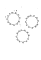
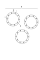
- FIG. 3 is a diagram illustrating a toner for developing an electrostatic latent image according to an exemplary embodiment. It is a figure explaining how to read the softening point Tm of binder resin. It is a figure which shows the toner for electrostatic latent image development of another aspect of this embodiment. It is a figure which shows the toner for electrostatic latent image development of another aspect of this embodiment. It is a figure which shows the toner for electrostatic latent image development of another aspect of this embodiment.
- the electrostatic latent image developing toner of the present embodiment (hereinafter also simply referred to as toner) includes a plurality of toner particles.
- Each of the plurality of toner particles contains a toner core containing a binder resin and a shell layer that covers the surface of the toner core.
- the shell layer contains a thermosetting resin and a wax.
- the toner core exhibits an anionic property (negative charging property), and the shell layer exhibits a cationic property (positive charging property).
- the electrostatic latent image developing toner 1 (hereinafter also simply referred to as toner 1) includes a plurality of toner particles 2.
- Each of the plurality of toner particles 2 includes a toner core 3 and a shell layer 4.
- a shell layer 4 is formed so as to cover the surface of the toner core 3.
- the shell layer 4 contains a wax 5 and a thermosetting resin.
- the particle size of the wax 5 is larger than the thickness of the shell layer 4, and protrudes from the toner core 3 from the surface of the shell layer 4 where the wax 5 is not present in a state where the wax 5 is covered with the shell layer 4.
- the shell layer 4 contains a thermosetting resin having a high hardness, the toner 1 is excellent in aggregation resistance, transportability, and storage stability.
- the electrostatic latent image developing toner 1 of this embodiment is supplied to a recording medium and heat and a load are applied, the shell layer 4 is destroyed. Then, due to the destruction of the shell layer 4, the toner core 3 exposed on the surface of the toner particles 2 is melted or softened and fixed to the recording medium.
- the wax 5 expands due to heat at the time of fixing, and becomes a starting point of destruction. Therefore, although the surface is covered with the shell layer 4, the shell layer 4 can be easily broken. As a result, it is possible to satisfactorily fix the toner particles 2 to the recording medium while sufficiently reducing the temperature and load when fixing to the recording medium.
- the toner core 3 contains a binder resin as an essential component.
- the binder resin has an anionic property.
- the binder resin preferably has, for example, an ester group, a hydroxyl group, a carboxyl group, an amino group, an ether group, an acid group, or a methyl group as a functional group in order to have an anionic property.
- the binder resin is preferably a resin having a functional group such as a hydroxyl group, a carboxyl group, or an amino group in the molecule, and more preferably a resin having a hydroxyl group and / or a carboxyl group in the molecule. This is because such a functional group chemically reacts with a thermosetting component (for example, methylol melamine) contained in the shell layer. As a result, in the toner 1, the shell layer 4 and the toner core 3 are firmly bonded.
- a thermosetting component for example, methylol melamine
- the acid value of the binder resin is preferably 3 mgKOH / g or more and 50 mgKOH / g or less in order to have a sufficient anionic property, and 10 mgKOH / g or more and 40 mgKOH / g or less. It is more preferable that
- the hydroxyl value of the binder resin is preferably 10 mgKOH / g or more and 70 mgKOH / g or less, and 15 mgKOH / g or more and 50 mgKOH / g or less in order to have sufficient anionic property. More preferably.
- the binder resin include thermoplastic resins (for example, styrene resin, acrylic resin, styrene acrylic resin, polyethylene resin, polypropylene resin, vinyl chloride resin, polyester resin, polyamide resin, polyurethane resin, polyvinyl alcohol resin). Vinyl ether resin, N-vinyl resin, or styrene-butadiene resin).
- a styrene acrylic resin or a polyester resin is preferable in order to improve the dispersibility of the colorant in the toner, the chargeability of the toner, and the fixing property to the recording medium.
- the styrene acrylic resin is a copolymer of a styrene monomer and an acrylic monomer.
- Specific examples of the styrene monomer include styrene, ⁇ -methylstyrene, p-hydroxystyrene, m-hydroxystyrene, vinyltoluene, ⁇ -chlorostyrene, o-chlorostyrene, m-chlorostyrene, p-chlorostyrene. Or p-ethylstyrene.
- acrylic monomer examples include (meth) acrylic acid; (meth) acrylic acid alkyl ester (methyl (meth) acrylate, ethyl (meth) acrylate, n-propyl (meth) acrylate, (meth) ) Iso-propyl acrylate, n-butyl (meth) acrylate, iso-butyl (meth) acrylate, 2-ethylhexyl (meth) acrylate, methyl (meth) acrylate, ethyl (meth) acrylate, (meth ) N-butyl acrylate or iso-butyl (meth) acrylate); (meth) acrylic acid hydroxyalkyl ester (2-hydroxyethyl (meth) acrylate, 3-hydroxypropyl (meth) acrylate, (meth) 2-hydroxypropyl acrylate or 4-hydroxypropyl (meth) acrylate).
- acrylic acid and methacrylic acid may be
- a monomer having a hydroxyl group for example, p-hydroxystyrene, m-hydroxystyrene, or (meth) acrylic acid hydroxyalkyl ester
- a hydroxyl group for example, p-hydroxystyrene, m-hydroxystyrene, or (meth) acrylic acid hydroxyalkyl ester
- a carboxyl group can be introduced into the styrene acrylic resin by using (meth) acrylic acid as a monomer.
- the acid value of the styrene acrylic resin can be adjusted by appropriately adjusting the amount of (meth) acrylic acid used.
- the polyester resin can be obtained by condensation polymerization or cocondensation polymerization of a divalent or trivalent or higher alcohol component and a divalent or trivalent or higher carboxylic acid component.
- divalent alcohol component examples include diols (for example, ethylene glycol, diethylene glycol, triethylene glycol, 1,2-propanediol, 1,3-propanediol, 1,4-butanediol, neopentyl glycol, 1 , 4-butenediol, 1,5-pentanediol, 1,6-hexanediol, 1,4-cyclohexanedimethanol, dipropylene glycol, polyethylene glycol, polypropylene glycol, or polytetramethylene glycol), or bisphenols (for example, Bisphenol A, hydrogenated bisphenol A, polyoxyethylenated bisphenol A, or polyoxypropylenated bisphenol A).
- diols for example, ethylene glycol, diethylene glycol, triethylene glycol, 1,2-propanediol, 1,3-propanediol, 1,4-butanediol, neopentyl glycol,
- trivalent or higher alcohol component examples include sorbitol, 1,2,3,6-hexanetetrol, 1,4-sorbitan, pentaerythritol, dipentaerythritol, tripentaerythritol, 1,2,4-butanetriol. 1,2,5-pentanetriol, glycerol, diglycerol, 2-methylpropanetriol, 2-methyl-1,2,4-butanetriol, trimethylolethane, trimethylolpropane, or 1,3,5-triol Hydroxymethylbenzene is mentioned.
- divalent carboxylic acid component examples include maleic acid, fumaric acid, citraconic acid, itaconic acid, glutaconic acid, phthalic acid, isophthalic acid, terephthalic acid, cyclohexanedicarboxylic acid, succinic acid, adipic acid, sebacic acid, and azelaic acid.
- alkyl (or alkenyl) succinic acid eg, n-butyl succinic acid, n-butenyl succinic acid, isobutyl succinic acid, isobutenyl succinic acid, n-octyl succinic acid, n-octenyl succinic acid, n-dodecyl succinic acid
- Acid n-dodecenyl succinic acid, isododecyl succinic acid, or isododecenyl succinic acid).
- Examples of the trivalent or higher carboxylic acid component include 1,2,4-benzenetricarboxylic acid (trimellitic acid), 1,2,5-benzenetricarboxylic acid, 2,5,7-naphthalenetricarboxylic acid, 1,2 , 4-Naphthalenetricarboxylic acid, 1,2,4-butanetricarboxylic acid, 1,2,5-hexanetricarboxylic acid, 1,3-dicarboxyl-2-methyl-2-methylenecarboxypropane, 1,2,4- Examples include cyclohexanetricarboxylic acid, tetra (methylenecarboxyl) methane, 1,2,7,8-octanetetracarboxylic acid, pyromellitic acid, or empole trimer acid.
- These carboxylic acid components may be used as ester-forming derivatives (for example, acid halides, acid anhydrides, or lower alkyl esters).
- “lower alkyl” means an al
- the adjustment of the acid value and the hydroxyl value of the polyester resin is carried out by adjusting the amount of the divalent or trivalent or higher alcohol component and the amount of the divalent or trivalent or higher carboxylic acid component, respectively, when producing the polyester resin. This can be done by changing as appropriate. Moreover, when the molecular weight of the polyester resin is increased, the acid value and hydroxyl value of the polyester resin tend to decrease.
- the number average molecular weight Mn of the polyester resin is preferably 1200 or more and 2000 or less in order to improve the strength of the toner core 3 and the fixing property of the electrostatic latent image developing toner 1.
- the molecular weight distribution of the polyester resin is preferably 9 or more and 20 or less for the same reason as described above.
- the number average molecular weight Mn of the styrene acrylic resin is preferably 2000 or more and 3000 or less in order to improve the strength of the toner core 3 and the fixability of the toner 1.
- the molecular weight distribution (mass average molecular weight Mw / number average molecular weight Mn) of the styrene acrylic resin is preferably 10 or more and 20 or less for the same reason as described above.
- the number average molecular weight Mn and the mass average molecular weight Mw of the binder resin can be measured using gel permeation chromatography.
- the glass transition point Tg of the binder resin is preferably equal to or lower than the curing start temperature of the thermosetting resin contained in the shell layer 4 in order to improve the low-temperature fixability.
- the glass transition point Tg of the binder resin is preferably 20 ° C. or higher, more preferably 30 ° C. or higher and 55 ° C. or lower, and further preferably 30 ° C. or higher and 50 ° C. or lower.
- the glass transition point Tg of the binder resin is 20 ° C. or more, the aggregation of the toner core 3 during the formation of the shell layer 4 can be suppressed.
- the hardening start temperature of a thermosetting resin is about 55 degreeC.
- the glass transition point Tg of the binder resin can be obtained from the change point of the specific heat of the binder resin using a differential scanning calorimeter (DSC). More specifically, a differential scanning calorimeter (for example, “DSC-6200” manufactured by Seiko Instruments Inc.) is used as a measuring apparatus, and the glass transition point Tg of the binder resin is measured by measuring the endothermic curve of the binder resin. Can be requested. Specifically, 10 mg of a measurement sample is put in an aluminum pan, an empty aluminum pan is used as a reference, and the endothermic curve of the binder resin is measured under the conditions of a measurement temperature range of 25 ° C. to 200 ° C. and a temperature increase rate of 10 ° C./min. And obtaining the glass transition point Tg of the binder resin based on this endothermic curve.
- DSC differential scanning calorimeter
- the softening point Tm of the binder resin is preferably 100 ° C. or less, and more preferably 95 ° C. or less. When the softening point Tm is 100 ° C. or lower, sufficient low-temperature fixability can be achieved even during high-speed fixing. In order to adjust the softening point Tm of the binder resin, for example, a plurality of binder resins having different softening points Tm may be combined.
- a Koka type flow tester for example, “CFT-500D” manufactured by Shimadzu Corporation
- a measurement sample is set on a Koka type flow tester, and a 1 cm 3 sample is measured under predetermined conditions (die pore diameter 1 mm, plunger load 20 kg / cm 2 , heating rate 6 ° C./min). It melts and flows out to obtain an S-shaped curve (that is, an S-shaped curve related to temperature (° C.) / Stroke (mm)), and the softening point Tm of the binder resin is read from the S-shaped curve.
- the maximum stroke value is S1
- the baseline stroke value lower than the temperature of S1 is S2.
- the temperature at which the stroke value in the S-shaped curve is (S1 + S2) / 2 is defined as the softening point Tm of the measurement sample (binder resin).
- the electrostatic latent image developing toner 1 will be described with reference to FIG.
- the toner core 3 can contain a known pigment or dye as a colorant in accordance with the color of the toner 1.
- the black colorant include carbon black.
- a colorant that is toned to black using a colorant such as a yellow colorant, a magenta colorant, or a cyan colorant, which will be described later, can also be used as the black colorant.
- examples of the colorant contained in the toner core 3 include a yellow colorant, a magenta colorant, and a cyan colorant.
- yellow colorant examples include condensed azo compounds, isoindolinone compounds, anthraquinone compounds, azo metal complexes, methine compounds, and allylamide compounds.
- C.I. I. Pigment Yellow (3, 12, 13, 14, 15, 17, 62, 74, 83, 93, 94, 95, 97, 109, 110, 111, 120, 127, 128, 129, 147, 151, 154, 155 168, 174, 175, 176, 180, 181, 191, or 194)
- Neftol Yellow S Hansa Yellow G
- C.I. I. Bat yellow is mentioned.
- magenta colorant examples include condensed azo compounds, diketopyrrolopyrrole compounds, anthraquinone compounds, quinacridone compounds, basic dye lake compounds, naphthol compounds, benzimidazolone compounds, thioindigo compounds, and perylene compounds.
- cyan colorant examples include copper phthalocyanine compounds, copper phthalocyanine derivatives, anthraquinone compounds, and basic dye lake compounds. Specifically, C.I. I. Pigment blue (1, 7, 15, 15: 1, 15: 2, 15: 3, 15: 4, 60, 62, or 66), phthalocyanine blue, C.I. I. Bat Blue, or C.I. I. Acid blue.
- the content of the colorant in the toner core 3 is preferably 1 part by mass or more and 10 parts by mass or less, and more preferably 3 parts by mass or more and 7 parts by mass or less with respect to 100 parts by mass of the binder resin.
- the toner core 3 contains a release agent for the purpose of improving the low temperature fixability of the electrostatic latent image developing toner 1 and suppressing offset or image smearing (stain around the image when the image is rubbed). Also good.
- mold release agents include aliphatic hydrocarbon waxes (eg, low molecular weight polyethylene, low molecular weight polypropylene, polyolefin copolymers, polyolefin wax, microcrystalline wax, paraffin wax, or Fischer-Tropsch wax), aliphatic hydrocarbons Oxides of waxes (eg, oxidized polyethylene wax or block copolymer of oxidized polyethylene wax), plant waxes (eg, candelilla wax, carnauba wax, wood wax, jojoba wax, or rice wax), animal systems Waxes (eg, beeswax, lanolin, or spermaceti), mineral waxes (eg, ozokerite, ceresin, or petrolatum), waxes based
- the content of the release agent is preferably 1 part by mass or more and 10 parts by mass or less with respect to 100 parts by mass of the binder resin.
- the content of the release agent is 1 part by mass or more, the occurrence of offset and image smearing during image formation can be satisfactorily suppressed.
- the content of the release agent is 10 parts by mass or less, when the manufactured toner core 3 is temporarily stored, the toner core 3 is not fused and stored until the shell layer 4 is formed. Stability can be maintained.
- the toner core 3 may contain a charge control agent as necessary. By containing the charge control agent, it is possible to improve the stability of the charge level and the charge rising characteristics, and to obtain a toner having excellent durability and stability.
- the charge rising characteristic is an index as to whether or not a predetermined charge level can be charged in a short time. Since the toner core 3 is anionic (negatively charged), a negatively chargeable charge control agent is used.
- the toner core 3 may contain magnetic powder as necessary.
- the electrostatic latent image developing toner 1 including the toner particle 2 is used as a magnetic one-component developer.
- suitable magnetic powders include iron (eg, ferrite or magnetite), ferromagnetic metals (eg, cobalt or nickel, etc.), alloys containing iron and / or ferromagnetic metals, iron and / or ferromagnetic metals. Examples thereof include a compound, a ferromagnetic alloy subjected to ferromagnetization treatment such as heat treatment, or chromium dioxide.
- the particle size of the magnetic powder is preferably 0.1 ⁇ m or more and 1.0 ⁇ m or less, and more preferably 0.1 ⁇ m or more and 0.5 ⁇ m or less.
- the particle size of the magnetic powder is 0.1 ⁇ m or more and 1.0 ⁇ m or less, it is easy to uniformly disperse the magnetic powder in the binder resin.
- the content of the magnetic powder is preferably 35 parts by mass or more and 60 parts by mass or less with respect to 100 parts by mass of the total amount of toner 1. It is more preferable that the amount be no less than 60 parts by mass.
- the shell layer 4 contains a thermosetting resin as an essential component.
- the thermosetting resin has sufficient strength, hardness, and cationic property.
- the thermosetting resin includes a unit in which a methylene group (—CH 2 —) derived from formaldehyde is introduced into a monomer such as melamine.
- thermosetting resins examples include melamine resin, urea resin (for example, urea resorcin resin), guanamine resin, urethane resin, amide resin, olefin resin, or gelatin / gum arabic resin.
- a melamine resin or a urea resin is preferable because it is not necessary to greatly increase the fixing temperature.
- the melamine resin is a polycondensate of melamine and formaldehyde, and the monomer used to form the melamine resin is melamine.
- Urea resin is a polycondensate of urea and formaldehyde, and the monomer used to form the urea resin is urea.
- Melamine or urea may have undergone well-known modification.
- the shell layer 4 may contain a resin other than the thermosetting resin as necessary as long as the effect of the present embodiment is not impaired.
- the content of the thermosetting resin in the shell layer 4 is preferably 50% by mass or more, and more preferably 70% by mass or more with respect to the total amount of the shell layer 4.
- the shell layer 4 has sufficient hardness
- the content of the thermosetting resin is 70% by mass or more, the shell layer 4 is Furthermore, it has sufficient hardness.
- the shell layer 4 preferably contains nitrogen atoms derived from melamine or urea.
- the content of nitrogen atoms in the shell layer 4 is preferably 10% by mass or more.
- the thickness of the shell layer 4 is, for example, 5 nm or more and 80 nm or less.
- the thickness of the shell layer 4 is measured, for example, by analyzing a cross-sectional TEM image of the electrostatic latent image developing toner 1 using commercially available image analysis software (for example, “WinROOF” manufactured by Mitani Corporation). it can.
- the wax 5 will be described below.
- the wax 5 becomes a starting point of the destruction of the shell layer 4, so that the shell layer 4 can be easily broken by heating and pressurization, and as a result, the temperature and load at the time of fixing are reduced. Can be low enough.
- the content of the wax 5 in the shell layer 4 is preferably 1.0% by mass or more and 25% by mass or less, and more preferably 5.0% by mass or more and 25% by mass or less with respect to the total amount of the shell layer 4. More preferred.
- the content of the wax 5 in the shell layer 4 is 1.0% by mass or more, the shell layer 4 is easily broken when the wax 5 becomes a starting point of the destruction of the shell layer 4. Temperature and load can be lowered sufficiently.
- the content of the wax 5 in the shell layer 4 is 25% by mass or less, the aggregation of the toner particles 2 when the electrostatic latent image developing toner 1 is stored at a high temperature can be suppressed. Heat resistant storage stability can be improved.
- the wax 5 is not particularly limited as long as it expands when heated.
- the same wax as the release agent that can be contained in the toner core 3 can be used.
- the wax 5 is preferably an ester wax or carnauba wax because it expands easily and has excellent versatility.
- the wax 5 may have a particle shape.
- the particle diameter is preferably 10 nm or more and 150 nm or less, more preferably 20 nm or more and 120 nm or less, and further preferably 50 nm or more and 100 nm or less.
- the particle size of the wax is 50 nm or more, the shell 5 is easily destroyed by the wax 5 being the starting point of the destruction of the shell layer 4, so that the temperature and load during fixing can be sufficiently lowered.
- the particle diameter of the wax is 100 nm or less, aggregation of the toner particles 2 when the electrostatic latent image developing toner 1 is stored at a high temperature can be suppressed, and the heat resistant storage stability of the toner 1 can be improved.
- the shell layer 4 may contain a charge control agent. Since the shell layer 4 is cationic (positively chargeable), it can contain a positively chargeable charge control agent.
- FIG. 3 shows an electrostatic latent image developing toner 6 according to another embodiment.
- the electrostatic latent image developing toner 6 includes a plurality of toner particles 7.
- Each of the plurality of toner particles 7 includes a toner core 3 and a shell layer 4.
- the shell layer 4 contains a thermosetting resin and a wax 5.
- the thickness of the shell layer 4 is larger than the particle size of the wax 5.
- the wax 5 is present uniformly in the shell layer 4 in contact with the surface of the toner core 3.
- FIG. 4 shows an electrostatic latent image developing toner 8 according to another embodiment.
- the electrostatic latent image developing toner 8 includes a plurality of toner particles 9.
- Each of the plurality of toner particles 9 includes a toner core 3 and a shell layer 4.
- the shell layer 4 contains a thermosetting resin and a wax 5.
- the wax 5 is uniformly present in the shell layer 4 while being separated from the surface of the toner core 3.
- FIG. 5 shows an electrostatic latent image developing toner 10 according to another embodiment.
- the electrostatic latent image developing toner 10 includes a plurality of toner particles 12.
- Each of the plurality of toner particles 12 includes a toner core 3 and a shell layer 4.
- the shell layer 4 contains a thermosetting resin and a wax 5.
- the toner particles 12 are obtained by externally treating the surface of the shell layer 4 with the external additive 11 with respect to the toner particles 2 in order to improve fluidity and handleability.
- the method for obtaining the toner particles 12 by performing an external addition process on the toner particles 2 using the external additive 11 is not particularly limited, and a known method is used. Specifically, the external additive conditions are adjusted so that the external additive 11 is not completely buried in the shell layer 4, and the external additive is added using a mixer (for example, FM mixer or Nauter mixer (registered trademark)). Processing is performed.
- a mixer for example, FM mixer or Nauter mixer (registered trademark)
- Examples of the external additive 11 include fine particles of silica fine particles or metal oxides (for example, alumina, titanium oxide, magnesium oxide, zinc oxide, strontium titanate, or barium titanate).
- the particle diameter of the external additive 11 is preferably 0.01 ⁇ m or more and 1.0 ⁇ m or less in order to improve fluidity and handling properties.
- the toner particles 2 (toner particles including the toner core 3, the shell layer 4, and the wax 5) before being processed by the external additive 11 may be referred to as “toner mother particles”.
- the amount of the external additive 11 used is preferably 1 part by mass or more and 10 parts by mass or less with respect to 100 parts by mass of the toner base particles in order to improve fluidity and handling properties. The following is more preferable.
- the electrostatic latent image developing toner has been described above with reference to FIGS.
- the electrostatic latent image developing toner may be used as a so-called one-component developer further containing, for example, ferrite or magnetite magnetic powder. Alternatively, it may be mixed with a desired carrier and used as a so-called two-component developer.
- the carrier is preferably a magnetic carrier.
- a carrier core material such as iron or magnetite coated with a resin can be used.
- the resin that coats the carrier core material examples include (meth) acrylic polymers, styrene polymers, styrene- (meth) acrylic copolymers, olefin polymers (eg, polyethylene, chlorinated polyethylene, or Polypropylene), polyvinyl chloride, polyvinyl acetate, polycarbonate resin, cellulose resin, polyester resin, unsaturated polyester resin, polyamide resin, polyurethane resin, epoxy resin, silicone resin, fluororesin (eg, polytetrafluoroethylene, polychlorotri Fluoroethylene or polyvinylidene fluoride), phenol resin, xylene resin, diallyl phthalate resin, polyacetal resin, or amino resin. These can be used alone or in combination of two or more.
- the resin covering the carrier core material is preferably a silicone resin.
- the ratio of the resin covering the carrier core material is preferably 1 part by mass or more and 5 parts by mass or less with respect to 100 parts by mass of the carrier core material.
- the particle size of the carrier is preferably 20 ⁇ m or more and 120 ⁇ m or less, and more preferably 25 ⁇ m or more and 80 ⁇ m or less.
- the particle size of the carrier can be measured with an electron microscope.
- the usage amount of the electrostatic latent image developing toner is 5% by mass or more and 20% by mass or less with respect to the total amount of the two-component developer. It is preferable that it is 5 mass% or more and 12 mass% or less.
- the manufacturing method of the electrostatic latent image developing toner 1 of the present embodiment includes a forming step of forming the shell layer 4 so as to cover the surface of the toner core 3 containing the binder resin.
- a preparatory step of preparing the toner core 3 including the binder resin may be included.
- components other than the binder resin for example, a colorant, a charge control agent, a release agent, or a magnetic powder
- a colorant for example, a colorant, a charge control agent, a release agent, or a magnetic powder
- examples of the method for executing the preparation step include a melt-kneading method or a polymerization method.
- the melt-kneading method is performed as follows. First, the binder resin and components other than the binder resin are mixed as necessary to obtain a mixture. Then, the obtained mixture is melt-kneaded, and the obtained melt-kneaded product is pulverized by a known method to obtain a pulverized product. The obtained pulverized product is classified by a known method to obtain a toner core 3 having a desired particle size.
- Examples of the polymerization method include the following methods. That is, a melt-kneaded material obtained in the same manner as in the melt-kneading method is atomized in the air using, for example, a disk or a multi-fluid nozzle to obtain the toner core 3; the toner core 3 is directly generated using the suspension polymerization method.
- Dispersion polymerization method in which the toner core 3 is directly formed using an aqueous organic solvent in which the monomer is soluble but the resulting polymer is insoluble; direct polymerization in the presence of a water-soluble polar polymerization initiator
- An emulsion polymerization method such as a so-called soap-free polymerization method for producing the toner core 3; or a hetero-aggregation method in which primary polar emulsion polymer particles are prepared, and then polar particles having opposite charges are added and associated with each other.
- the forming step is a step of forming the shell layer 4 so as to cover the surface of the toner core 3.
- the forming step includes a wax dispersion preparing step, a shell layer forming solution preparing step, a supplying step, and a resinification step.
- a dispersion containing the wax 5 (wax dispersion) is prepared.
- a shell layer forming liquid preparation step a shell layer forming liquid is prepared.
- the shell layer forming liquid contains a wax dispersion and a polymer and / or prepolymer of a thermosetting resin.
- the supplying step the shell layer forming liquid is supplied to the surface of the toner core 3.
- the resinification step the polymer and / or prepolymer of the thermosetting resin is resinized.
- the wax dispersion is prepared by mixing the wax 5 with an arbitrary solvent and various additives (for example, a surfactant) as required, and mixing with stirring as appropriate.
- a surfactant for example, a surfactant
- the kind of solvent is not specifically limited, For example, toluene, acetone, methyl ethyl ketone, tetrahydrofuran, or water is mentioned.
- the wax dispersion obtained in the wax dispersion preparation step is added to the mixture of the thermosetting resin monomer and / or the prepolymer and the solvent, and the mixture is appropriately stirred. What is necessary is just to mix. It is preferable to adjust the pH to about 4 during the stirring and mixing.
- the monomer of the above thermosetting resin is appropriately selected. Further, the prepolymer of the thermosetting resin is in a state before the polymer in which the degree of polymerization of the monomer of the thermosetting resin is increased to some extent, and is also referred to as an initial polymer or an initial condensate.
- the shell layer forming liquid may contain a known dispersant in order to improve the dispersibility of the thermosetting resin monomer and / or prepolymer in the solvent.
- the content of the dispersant in the shell layer forming liquid is, for example, 0.1% by mass or more and 15% by mass or less. Dispersibility can be satisfactorily expressed when the content of the dispersant in the shell layer forming liquid is 0.1% by mass or more. On the other hand, when the content of the dispersant in the shell layer forming liquid is 15% by mass or less, the environmental load due to the dispersant can be reduced.
- the dispersant can be removed by a process such as washing after the electrostatic latent image developing toner 1 of the present embodiment is manufactured.
- the shell layer forming liquid is supplied to the toner core 3.
- the method of performing the supplying step include a method of spraying a shell layer forming liquid on the surface of the toner core 3 or a method of immersing the toner core 3 in the shell layer forming liquid.
- the shell layer forming liquid may be diluted with the above-mentioned arbitrary solvent.
- the monomer and / or prepolymer of the thermosetting resin contained in the shell layer forming liquid is resinized by arbitrary polymerization or condensation to form a thermosetting resin.
- the shell layer 4 is formed on the surface of the toner core 3.
- Resinification includes not only complete resinization with a sufficiently high degree of polymerization but also partial resination with a medium degree of polymerization.
- the temperature during the resinification step is preferably maintained in the range of 40 ° C. or higher and 90 ° C. or lower, and more preferably maintained in the range of 50 ° C. or higher and 80 ° C. or lower.
- the temperature is preferably maintained in the range of 40 ° C. or higher and 90 ° C. or lower, and more preferably maintained in the range of 50 ° C. or higher and 80 ° C. or lower.
- the manufacturing method of this embodiment has been described above.
- the electrostatic latent image developing toner after the resinification step is subjected to at least one step selected from a cleaning step, a drying step, and an external addition step as necessary. You may pass.
- the electrostatic latent image developing toner 1 obtained by executing the forming step is washed with, for example, water.
- the washed electrostatic latent image developing toner 1 is dried by a dryer (for example, a spray dryer, a fluidized bed dryer, a vacuum freeze dryer, or a vacuum dryer).
- a spray dryer is preferably used because aggregation of the toner particles 2 contained in the electrostatic latent image developing toner 1 during drying is easily suppressed.
- the dispersion liquid in which the external additive 11 for example, silica fine particles
- the external addition process described later can be performed simultaneously.
- the external additive 11 is attached to the surface of the toner particles 2.
- the external additive conditions are adjusted so that the external additive 11 is not completely buried in the surface of the shell layer 4, and a mixer (for example, FM mixer or Nauter mixer ( (Registered trademark)) and the electrostatic latent image developing toner 1 and the external additive 11 are mixed to produce the electrostatic latent image developing toner 10.
- a mixer for example, FM mixer or Nauter mixer ( (Registered trademark)
- the electrostatic latent image developing toner 1 and the external additive 11 are mixed to produce the electrostatic latent image developing toner 10.
- the toner for developing an electrostatic latent image of the present embodiment has a fixing temperature higher than that in the case of using the toner for developing an electrostatic latent image including toner particles in which the shell layer 4 not containing the wax 5 is formed. It can be lowered sufficiently. As a result, since the load due to heat is reduced, it is possible to improve the durability of the recording medium, and it is possible to suppress deterioration and cost increase of members constituting the fixing device.
- Wax Dispersion B Ester wax (“WEP-3” manufactured by NOF Corporation) was used as the wax. 40 parts by mass of ester wax, 1 part by mass of sodium dodecylbenzenesulfonate as an anionic surfactant, and 59 parts by mass of ion-exchanged water were put into a stirring device equipped with stirring blades. This was heated to 90 ° C. with stirring, and then emulsified with a homogenizer (“Ultra Tarrax T50” manufactured by IKA) for 5 minutes. Thereafter, emulsification was performed at 100 ° C. using a gorin homogenizer (“15M-8TA type” manufactured by APV) to prepare wax dispersion B. When the particle size of the wax in the wax dispersion B was measured with a laser diffraction / scattering particle size distribution analyzer (“LA-950V” manufactured by Horiba, Ltd.), the average volume particle size was 20 nm.
- LA-950V laser diffraction / scattering particle
- Wax Dispersion D An ester wax (“WEP-3” manufactured by NOF Corporation) was used as a wax. 40 parts by mass of ester wax, 0.2 part by mass of sodium dodecylbenzenesulfonate as an anionic surfactant, and 59.8 parts by mass of ion-exchanged water were put into a stirring device equipped with a blade. The mixture was heated to 90 ° C. with stirring, and then emulsified with a homogenizer (“Ultra Turrax T50” manufactured by IKA) for 5 minutes. Thereafter, emulsification was performed at 90 ° C. using a gorin homogenizer (“15M-8TA type” manufactured by APV) to prepare wax dispersion D. When the particle size of the wax in the wax dispersion D was measured with a laser diffraction / scattering particle size distribution analyzer (“LA-950V” manufactured by Horiba, Ltd.), the average volume particle size was 120 nm.
- LA-950V laser dif
- Carnauba wax (“Carnauba Wax No. 1” manufactured by Kato Yoko Co., Ltd.) was used as the wax. 40 parts by mass of carnauba wax, 0.5 part by mass of sodium dodecylbenzenesulfonate as an anionic surfactant, and 59.5 parts by mass of ion-exchanged water were charged into a stirring apparatus equipped with stirring blades. While stirring, the mixture was heated to 90 ° C. and then emulsified with a homogenizer (“Ultra Turrax T50” manufactured by IKA) for 5 minutes. Thereafter, emulsification was performed at 90 ° C.
- a homogenizer (“Ultra Turrax T50” manufactured by IKA)
- wax dispersion E was prepared using a gorin homogenizer (“15M-8TA type” manufactured by APV) to prepare wax dispersion E.
- 15M-8TA type manufactured by APV
- LA-950V laser diffraction / scattering particle size distribution analyzer
- Shell Layer Forming Liquid B 100 parts by mass of an aqueous methylolmelamine solution (“Milben 607” manufactured by Showa Denko KK, solid content concentration: 80% by mass) and 22.3 parts by mass of wax dispersion A (solid content of 8. 9 parts by mass). This was put into a beaker and stirred for 30 minutes at 300 rpm using a mechanically controlled stirrer (“RW20 Digital” manufactured by IKA) and a stirring blade to form shell layer forming solution B (wax in the shell in the solid content) Content: 10% by mass).
- RW20 Digital mechanically controlled stirrer
- Shell Layer-Forming Liquid C 100 parts by mass of an aqueous methylolmelamine solution (“Milben 607” manufactured by Showa Denko KK, solid content concentration: 80% by mass) and 66.7 parts by mass of wax dispersion A (solid content of 26. 7 parts by mass). This was put into a beaker and stirred for 30 minutes at 300 rpm using a mechanically controlled stirrer (“RW20 Digital” manufactured by IKA) and a stirring blade, and a shell layer forming liquid C (wax in shell in solid content) Content: 25% by mass).
- RW20 Digital mechanically controlled stirrer
- Shell Layer Forming Liquid D 100 parts by mass of a methylolmelamine aqueous solution (“Milben 607” manufactured by Showa Denko KK, solid content concentration: 80% by mass) and 74.0 parts by mass of wax dispersion A (solid content 29.29%). 6 parts by mass). This was put into a beaker and stirred for 30 minutes at 300 rpm using a mechanically controlled stirrer (“RW20 Digital” manufactured by IKA) and a stirring blade to form shell layer forming solution D (wax in the shell in the solid content) Content: 27% by mass).
- RW20 Digital mechanically controlled stirrer
- Shell Layer Forming Liquid E 100 parts by mass of an aqueous methylolmelamine solution (“Milben 607” manufactured by Showa Denko KK, solid content concentration: 80% by mass) and 22.3 parts by mass of wax dispersion B (solid content: 8. 9 parts by mass). This was put into a beaker and stirred for 30 minutes at 300 rpm using a mechanically controlled stirrer (“RW20 Digital” manufactured by IKA) and a stirring blade, and a shell layer forming solution E (wax in the shell in the solid content) Content: 10% by mass).
- RW20 Digital mechanically controlled stirrer
- Shell Layer-Forming Liquid F 100 parts by mass of an aqueous methylolmelamine solution (“Milben 607” manufactured by Showa Denko KK, solid content concentration: 80% by mass) and 22.3 parts by mass of wax dispersion C (solid content of 8. 9 parts by mass). This was put into a beaker and stirred for 30 minutes at 300 rpm using a mechanically controlled stirrer (“RW20 Digital” manufactured by IKA) and a stirring blade, and the shell layer forming solution F (the wax in the shell in the solid content) Content: 10% by mass).
- RW20 Digital mechanically controlled stirrer
- Shell Layer-Forming Liquid G 100 parts by mass of a methylolmelamine aqueous solution (“Milben 607” manufactured by Showa Denko KK, solid content concentration: 80% by mass) and 22.3 parts by mass of wax dispersion D (solid content of 8. 9 parts by mass). This was put into a beaker and stirred for 30 minutes at 300 rpm using a mechanically controlled stirrer (“RW20 Digital” manufactured by IKA) and a stirring blade, and a shell layer forming solution G (wax in shell in solid content) Content: 10% by mass).
- RW20 Digital mechanically controlled stirrer
- Shell Layer Forming Liquid H 100 parts by mass of a methylolmelamine aqueous solution (“Milben 607” manufactured by Showa Denko KK, solid content concentration: 80% by mass) and 22.3 parts by mass of wax dispersion E (solid content of 8. 9 parts by mass). This was put into a beaker and stirred for 30 minutes at 300 rpm using a mechanically controlled stirrer (“RW20 Digital” manufactured by IKA) and a stirring blade, and the shell layer forming liquid H (wax in the shell in the solid content) Content: 10% by mass).
- RW20 Digital mechanically controlled stirrer
- Example 1 (Preparation of toner core) A polyester resin as a binder resin was prepared. Regarding the physical properties of this polyester resin, the acid value was 40 mgKOH / g, the hydroxyl value was 20 mgKOH / g, the softening point Tm was 100 ° C., and the glass transition point Tg was 48 ° C. 100 parts by mass of this polyester resin, 5 parts by mass of a colorant (CI Pigment Blue 15: 3 type (copper phthalocyanine)), and ester wax as a release agent (“WEP-3” manufactured by NOF Corporation) ) 5 parts by mass were mixed and mixed with an FM mixer.
- a colorant CI Pigment Blue 15: 3 type (copper phthalocyanine)
- WEP-3 ester wax as a release agent
- the obtained mixture was melt-kneaded with a twin screw extruder (“PCM-30” manufactured by Ikegai Co., Ltd.).
- the obtained melt-kneaded product is pulverized with a mechanical pulverizer (“Turbo Mill” manufactured by Freund Turbo Co., Ltd.), then classified with a classifier (“Elbow Jet” manufactured by Nittetsu Mining Co., Ltd.), and a volume average particle size of 6 ⁇ m.
- a toner core having a diameter was obtained.
- the toner core had a circularity of 0.93.
- the toner core had a glass transition point Tg of 49 ° C. and a softening point Tm of 90 ° C.
- a 1 L three-necked flask was set in a 30 ° C. water bath, and the pH of ion-exchanged water (300 mL) was adjusted to 4 using hydrochloric acid in the flask.
- ion-exchanged water 6.7 g of the shell layer forming liquid A was added and dissolved, and 300 g of the toner core was added thereto and stirred at a speed of 200 rpm for 1 hour.
- a wet cake of the toner particles was filtered from the liquid containing the toner particles using a Buchner funnel.
- the toner particle wet cake was again dispersed in ion exchange water to wash the toner particles.
- the same washing of the toner particles with ion exchange water was repeated 5 times.
- the toner particles recovered by filtration were left to dry in a 40 ° C. atmosphere for 48 hours.
- the electrical conductivity of the filtrate after filtration was 4 ⁇ S / cm.
- dry silica is added so that the external additive amount of dry silica (“RA200HS” manufactured by Nippon Aerosil Co., Ltd., particle size: 12 ⁇ m) is 0.5 mass% with respect to the total amount of toner particles.
- the surface of the toner particles was externally added to obtain the electrostatic latent image developing toner of Example 1.
- Example 2 The electrostatic latent image development of Example 2 was performed in the same manner as in Example 1 except that 7.3 g of shell layer forming liquid B was used instead of 6.7 g of shell layer forming liquid A. Toner was obtained.
- Example 3 The electrostatic latent image development of Example 3 was performed in the same manner as in Example 1 except that 8.3 g of shell layer forming liquid C was used instead of 6.7 g of shell layer forming liquid A. Toner was obtained.
- Example 4 The electrostatic latent image development of Example 4 was performed in the same manner as in Example 1 except that 8.4 g of shell layer forming liquid D was used instead of 6.7 g of shell layer forming liquid A. Toner was obtained.
- Comparative Example 1 The electrostatic latent image developing toner of Comparative Example 1 was obtained in the same manner as in Example 1, except that 6.6 g of Milben 607 was used instead of 6.7 g of the shell layer forming liquid A. It was.
- Example 5 An electrostatic latent image developing toner of Example 5 was obtained in the same manner as in Example 2, except that the shell layer forming liquid E was used instead of the shell layer forming liquid B.
- Example 6 An electrostatic latent image developing toner of Example 6 was obtained in the same manner as in Example 2, except that the shell layer forming liquid F was used instead of the shell layer forming liquid B.
- Example 7 An electrostatic latent image developing toner of Example 7 was obtained in the same manner as in Example 2 except that the shell layer forming liquid G was used instead of the shell layer forming liquid B.
- Example 8 An electrostatic latent image developing toner of Example 8 was obtained in the same manner as in Example 2, except that the shell layer forming liquid H was used instead of the shell layer forming liquid B.
- the evaluation method or measurement method of the electrostatic latent image developing toner obtained in the examples and comparative examples is shown below.
- the following evaluation was performed using a two-component developer.
- a method for preparing a two-component developer is shown below.
- Ferrite (“EF-35B” manufactured by Powder Tech Co., Ltd., particle size: 35 ⁇ m) was prepared as a carrier core material.
- 30 g of polyamideimide resin is diluted with 2 liters of water, 120 g of tetrafluoroethylene / hexafluoropropylene copolymer (FEP) is dispersed therein, and 3 g of silicon oxide is further dispersed therein to form a coating layer forming solution.
- FEP tetrafluoroethylene / hexafluoropropylene copolymer
- silicon oxide is further dispersed therein to form a coating layer forming solution.
- This coating layer forming liquid and 10 kg of the above ferrite were put into a coating apparatus having a fluidized bed, and the coating layer forming liquid was applied to the surface of the ferrite.
- Minimum fixing temperature (low temperature fixability)
- a color complex machine (“TASKalfa 5550ci” manufactured by Kyocera Document Solutions Inc.) provided with a fixing device (fixing jig) modified so that the fixing temperature can be adjusted was used.
- the two-component developer was put into the developing device of the evaluation machine, the toner for developing the electrostatic latent image was put into the toner container of the evaluation machine, and the fixing temperature when the image was output was adjusted. Specifically, the fixing temperature was changed at 5 ° C. increments up to 200 ° C.
- the fixing conditions in the case of fixing the toner for developing an electrostatic latent image 1.0 mg / cm 2 on a sheet of 90 g / m 2
- the minimum temperature at which the electrostatic latent image developing toner is satisfactorily fixed is adopted as the minimum fixing temperature.
- the measurement conditions for the minimum fixing temperature were a speed of 230 mm / second, a nip width of 8 mm, and a nip passage time of 35 msec. A sample having a minimum fixing temperature of 160 ° C. or lower was regarded as acceptable.
- Table 1 shows the evaluation results of the electrostatic latent image developing toners obtained in Examples 1 to 8 and Comparative Example 1.
- “-” indicates that the shell layer did not contain wax.
- the electrostatic latent image developing toners of the present embodiment obtained in Examples 1 to 8 were excellent in low-temperature fixability. Further, Examples 1 to 3, 5, 6 and 8, which are preferred embodiments, were excellent in heat resistant storage stability. On the other hand, the electrostatic latent image developing toner obtained in Comparative Example 1 was inferior in low-temperature fixability because the shell layer contained no wax.
- the toner for developing an electrostatic latent image of this embodiment is excellent in low-temperature fixability, can obtain a good quality image, and is suitably used for image formation.
Landscapes
- Physics & Mathematics (AREA)
- General Physics & Mathematics (AREA)
- Spectroscopy & Molecular Physics (AREA)
- Developing Agents For Electrophotography (AREA)
Abstract
本発明の静電潜像現像用トナー(1)は、複数のトナー粒子(2)を含む。複数のトナー粒子(2)の各々は、結着樹脂を含むトナーコア(3)と、トナーコア(3)の表面を被覆するシェル層(4)とを含有する。シェル層(4)は熱硬化性樹脂とワックス(5)とを含有する。ワックス(5)の含有量はシェル層(4)に対して1.0質量%以上25質量%以下であることが好ましい。
Description
本発明は、静電潜像現像用トナー、及び静電潜像現像用トナーの製造方法に関する。
複写機等の画像形成に関する技術領域においては、例えば定着ローラーを用いた加熱及び加圧により、紙のような記録媒体に静電潜像現像用トナーを定着させる。具体的には、加熱及び加圧によりトナー中のトナー成分が溶融又は軟化し、記録媒体に定着する。この定着について、定着時の省エネルギー化及び定着装置の小型化が求められている。そのため、定着ローラーの加熱及び加圧を抑えつつ、記録媒体に対して良好に定着し得るトナーが望まれている。
上記のような画像形成に用いられるトナーとして、表面が熱硬化性樹脂のシェル層で被覆されたトナーが知られている。しかし、このようなトナーを定着させる場合には、熱硬化性樹脂の硬度が非常に高いため、定着温度又は定着荷重が高いことが必要とされる。その結果、コストアップ等に繋がる場合があった。
このような問題を解決するため、例えば、熱硬化性樹脂の中でも比較的柔軟な尿素樹脂で表面が被覆されたトナーが提案されている(特許文献1)。また、熱硬化性樹脂を含み、かつ微細な貫通孔が設けられたシェル層により、トナーコアが被覆されたトナーが提案されている(例えば、特許文献2)。
しかし、特許文献1に記載のトナーを定着させる場合は、依然として、定着温度及び定着荷重が高いものであることが必要とされる。その結果、コストアップ等に繋がる場合がある。
また、特許文献2に記載のカプセルトナーにおいては、貫通孔が破壊の起点となったシェル層が容易に破壊されるため、定着時の加熱及び加圧を低減できる。しかしながら、特許文献2に記載されたトナーを保存する際に、微細な貫通孔からトナーコアに含まれる材料が浸み出すため、高温下で保存する場合にはトナー粒子同士の凝集が発生する場合がある。つまり、耐熱保存性に劣る場合がある。
本発明は上記のような従来技術の問題に鑑みてなされたものであり、その目的は、硬い熱硬化性樹脂で表面が被覆されていても十分に低い定着温度及び定着荷重(定着圧力)での定着を達成できる静電潜像現像用トナーを提供することである。さらに、本発明の目的は、上記の静電潜像現像用トナーの製造方法を提供することである。
上記のような課題を解決するため、本発明は以下を要旨とする。すなわち、本発明の静電潜像現像用トナーは、複数のトナー粒子を含む。複数のトナー粒子の各々は、結着樹脂を含むトナーコアとトナーコアの表面を被覆するシェル層とを含有する。シェル層は熱硬化性樹脂とワックスとを含有する。
また、本発明の静電潜像現像用トナーの製造方法は、結着樹脂を含むトナーコアの表面を被覆するようにシェル層を形成する形成工程を含む。形成工程は、ワックスを含有する分散液を調製するワックス分散液調製工程と、上記分散液を含むシェル層形成用液を調製するシェル層形成用液調製工程と、トナーコアの表面に、熱硬化性樹脂のポリマー及び/又はプレポリマーと前記分散液とを含むシェル層形成用液を供給する供給工程と、熱硬化性樹脂のポリマー及び/又はプレポリマーを樹脂化する樹脂化工程とを含む。
本発明によれば、硬度の高い熱硬化性樹脂を含むシェル層により表面が被覆されているにも関わらず、十分に低い定着温度及び定着荷重(定着圧力)での定着を達成できる静電潜像現像用トナーを提供することができる。
以下、本発明の実施形態について詳細に説明する。本発明は、以下の実施形態に何ら限定されるものではなく、本発明の目的の範囲内で適宜変更を加えて実施することができる。なお、説明が重複する箇所については適宜説明を省略する場合があるが、発明の要旨を限定するものではない。
本実施形態の静電潜像現像用トナー(以下、単にトナーともいう)は、複数のトナー粒子を含む。複数のトナー粒子の各々は、結着樹脂を含むトナーコアと、トナーコアの表面を被覆するシェル層とを含有する。シェル層は熱硬化性樹脂とワックスとを含有する。なお、本実施形態において、トナーコアはアニオン性(負帯電性)を示し、シェル層はカチオン性(正帯電性)を示す。
本実施形態の静電潜像現像用トナーについて、図1を参照して説明する。図1に示すように、静電潜像現像用トナー1(以下、単にトナー1ともいう)は、複数のトナー粒子2を含む。複数のトナー粒子2の各々は、トナーコア3とシェル層4とを含有する。そして、トナーコア3の表面を被覆するようにシェル層4が形成されている。シェル層4はワックス5と熱硬化性樹脂とを含有する。シェル層4の厚さよりもワックス5の粒径が大きく、ワックス5がシェル層4に被覆された状態でワックス5が存在しないシェル層4の表面よりもトナーコア3から突出している。
シェル層4が硬度の高い熱硬化性樹脂を含むことにより、トナー1は、耐凝集性、搬送性、及び保存性に優れる。本実施形態の静電潜像現像用トナー1が記録媒体に供給され、熱及び荷重が付与されると、シェル層4が破壊される。そして、シェル層4の破壊により、トナー粒子2の表面に露出したトナーコア3が溶融又は軟化して記録媒体に定着される。
トナー粒子2においては、ワックス5が定着時の熱により膨張し、破壊の起点となる。そのため、シェル層4で表面が被覆されているにも関わらず、シェル層4を容易に破壊できる。その結果、記録媒体に定着する際の温度及び荷重を十分に下げつつ、トナー粒子2を良好に記録媒体に定着できる。
トナーコア3について以下に説明する。トナーコア3は必須成分として結着樹脂を含有する。結着樹脂はアニオン性を有する。結着樹脂は、アニオン性を有するために、例えば、官能基としてエステル基、水酸基、カルボキシル基、アミノ基、エーテル基、酸基、又はメチル基を有することが好ましい。結着樹脂は、分子中に水酸基、カルボキシル基、又はアミノ基のような官能基を有する樹脂が好ましく、分子中に水酸基及び/又はカルボキシル基を有する樹脂がより好ましい。なぜなら、このような官能基は、シェル層に含まれる熱硬化性成分(例えば、メチロールメラミン)と反応して化学的に結合するからである。その結果、トナー1においては、シェル層4とトナーコア3とが強固に結合する。
結着樹脂がカルボキシル基を有する場合、この結着樹脂の酸価は、十分なアニオン性を有するために、3mgKOH/g以上50mgKOH/g以下であることが好ましく、10mgKOH/g以上40mgKOH/g以下であることがより好ましい。
結着樹脂が水酸基を有する場合、この結着樹脂の水酸基価は、十分なアニオン性を有するために、10mgKOH/g以上70mgKOH/g以下であることが好ましく、15mgKOH/g以上50mgKOH/g以下であることがより好ましい。
結着樹脂の具体例としては、熱可塑性樹脂(例えば、スチレン樹脂、アクリル樹脂、スチレンアクリル系樹脂、ポリエチレン樹脂、ポリプロピレン樹脂、塩化ビニル系樹脂、ポリエステル樹脂、ポリアミド樹脂、ポリウレタン樹脂、ポリビニルアルコール系樹脂、ビニルエーテル系樹脂、N-ビニル系樹脂、又はスチレン-ブタジエン樹脂)が挙げられる。結着樹脂としては、トナー中の着色剤の分散性、トナーの帯電性、及び記録媒体に対する定着性を向上させるために、スチレンアクリル系樹脂又はポリエステル樹脂が好ましい。
スチレンアクリル系樹脂は、スチレン系単量体とアクリル系単量体との共重合体である。スチレン系単量体の具体例としては、スチレン、α-メチルスチレン、p-ヒドロキシスチレン、m-ヒドロキシスチレン、ビニルトルエン、α-クロロスチレン、o-クロロスチレン、m-クロロスチレン、p-クロロスチレン、又はp-エチルスチレンが挙げられる。
アクリル系単量体の具体例としては、(メタ)アクリル酸;(メタ)アクリル酸アルキルエステル((メタ)アクリル酸メチル、(メタ)アクリル酸エチル、(メタ)アクリル酸n-プロピル、(メタ)アクリル酸iso-プロピル、(メタ)アクリル酸n-ブチル、(メタ)アクリル酸iso-ブチル、(メタ)アクリル酸2-エチルヘキシル、(メタ)アクリル酸メチル、(メタ)アクリル酸エチル、(メタ)アクリル酸n-ブチル、又は(メタ)アクリル酸iso-ブチル);(メタ)アクリル酸ヒドロキシアルキルエステル((メタ)アクリル酸2-ヒドロキシエチル、(メタ)アクリル酸3-ヒドロキシプロピル、(メタ)アクリル酸2-ヒドロキシプロピル、又は(メタ)アクリル酸4-ヒドロキシプロピル)が挙げられる。なお、アクリル酸及びメタクリル酸の各々を、「(メタ)アクリル酸」と、アクリル酸エステル及びメタクリル酸エステルの各々を「(メタ)アクリレート」と、それぞれ総称する場合がある。
スチレンアクリル系樹脂を調製する際に、水酸基を有する単量体(例えば、p-ヒドロキシスチレン、m-ヒドロキシスチレン、又は(メタ)アクリル酸ヒドロキシアルキルエステル)を用いることで、スチレンアクリル系樹脂に水酸基を導入できる。水酸基を有する単量体の使用量を適宜調整することで、スチレンアクリル系樹脂の水酸基価を調整できる。
スチレンアクリル系樹脂を調製する際に、(メタ)アクリル酸を単量体として用いることで、スチレンアクリル系樹脂にカルボキシル基を導入できる。(メタ)アクリル酸の使用量を適宜調整することで、スチレンアクリル系樹脂の酸価を調整できる。
ポリエステル樹脂は、2価又は3価以上のアルコール成分と2価又は3価以上のカルボン酸成分とを縮重合や共縮重合することで得られる。
2価のアルコール成分としては、例えば、ジオール類(例えば、エチレングリコール、ジエチレングリコール、トリエチレングリコール、1,2-プロパンジオール、1,3-プロパンジオール、1,4-ブタンジオール、ネオペンチルグリコール、1,4-ブテンジオール、1,5-ペンタンジオール、1,6-ヘキサンジオール、1,4-シクロヘキサンジメタノール、ジプロピレングリコール、ポリエチレングリコール、ポリプロピレングリコール、又はポリテトラメチレングリコール)、又はビスフェノール類(例えば、ビスフェノールA、水素添加ビスフェノールA、ポリオキシエチレン化ビスフェノールA、又はポリオキシプロピレン化ビスフェノールA)が挙げられる。
3価以上のアルコール成分としては、例えば、ソルビトール、1,2,3,6-ヘキサンテトロール、1,4-ソルビタン、ペンタエリスリトール、ジペンタエリスリトール、トリペンタエリスリトール、1,2,4-ブタントリオール、1,2,5-ペンタントリオール、グリセロール、ジグリセロール、2-メチルプロパントリオール、2-メチル-1,2,4-ブタントリオール、トリメチロールエタン、トリメチロールプロパン、又は1,3,5-トリヒドロキシメチルベンゼンが挙げられる。
2価のカルボン酸成分としては、例えば、マレイン酸、フマル酸、シトラコン酸、イタコン酸、グルタコン酸、フタル酸、イソフタル酸、テレフタル酸、シクロヘキサンジカルボン酸、コハク酸、アジピン酸、セバシン酸、アゼライン酸、マロン酸、又はアルキル(若しくはアルケニル)コハク酸(例えば、n-ブチルコハク酸、n-ブテニルコハク酸、イソブチルコハク酸、イソブテニルコハク酸、n-オクチルコハク酸、n-オクテニルコハク酸、n-ドデシルコハク酸、n-ドデセニルコハク酸、イソドデシルコハク酸、又はイソドデセニルコハク酸)が挙げられる。
3価以上のカルボン酸成分としては、例えば、1,2,4-ベンゼントリカルボン酸(トリメリット酸)、1,2,5-ベンゼントリカルボン酸、2,5,7-ナフタレントリカルボン酸、1,2,4-ナフタレントリカルボン酸、1,2,4-ブタントリカルボン酸、1,2,5-ヘキサントリカルボン酸、1,3-ジカルボキシル-2-メチル-2-メチレンカルボキシプロパン、1,2,4-シクロヘキサントリカルボン酸、テトラ(メチレンカルボキシル)メタン、1,2,7,8-オクタンテトラカルボン酸、ピロメリット酸、又はエンポール三量体酸が挙げられる。これらのカルボン酸成分は、エステル形成性誘導体(例えば、酸ハライド、酸無水物、又は低級アルキルエステル)として用いてもよい。ここで、「低級アルキル」とは、炭素原子数1から6のアルキル基を意味する。
ポリエステル樹脂の酸価及び水酸基価の調整は、ポリエステル樹脂を製造する際に、2価又は3価以上のアルコール成分の使用量と2価又は3価以上のカルボン酸成分の使用量とを、それぞれ適宜変更することで行うことができる。また、ポリエステル樹脂の分子量を上げると、ポリエステル樹脂の酸価及び水酸基価は低下する傾向がある。
結着樹脂がポリエステル樹脂である場合、ポリエステル樹脂の数平均分子量Mnは、トナーコア3の強度及び静電潜像現像用トナー1の定着性の向上のために、1200以上2000以下であることが好ましい。ポリエステル樹脂の分子量分布(数平均分子量Mnに対する質量平均分子量Mwの比率、質量平均分子量Mw/数平均分子量Mn)は、上記と同様の理由から、9以上20以下であることが好ましい。
結着樹脂がスチレンアクリル系樹脂である場合、スチレンアクリル系樹脂の数平均分子量Mnは、トナーコア3の強度及びトナー1の定着性の向上のために、2000以上3000以下であることが好ましい。スチレンアクリル系樹脂の分子量分布(質量平均分子量Mw/数平均分子量Mn)は、上記と同様の理由から、10以上20以下であることが好ましい。なお、結着樹脂の数平均分子量Mnと質量平均分子量Mwは、ゲルパーミエーションクロマトグラフィーを用いて測定できる。
結着樹脂のガラス転移点Tgは、低温定着性を向上させるために、シェル層4に含まれる熱硬化性樹脂の硬化開始温度以下であることが好ましい。結着樹脂のガラス転移点Tgが上記硬化開始温度以下であることで、高速定着時においても十分な低温定着性が得られる。特に、結着樹脂のガラス転移点Tgは20℃以上であることが好ましく、30℃以上55℃以下であることがより好ましく、30℃以上50℃以下であることがさらに好ましい。結着樹脂のガラス転移点Tgが20℃以上である場合は、シェル層4の形成時にトナーコア3が凝集することを抑制できる。なお、後述するが、一般に、熱硬化性樹脂の硬化開始温度は55℃程度である。
結着樹脂のガラス転移点Tgは、示差走査熱量計(DSC)を用い、結着樹脂の比熱の変化点から求めることができる。より具体的には、測定装置として示差走査熱量計(例えば、セイコーインスツル株式会社製「DSC-6200」)を用い、結着樹脂の吸熱曲線を測定することで結着樹脂のガラス転移点Tgを求めることができる。詳細には、測定試料10mgをアルミパン中に入れ、リファレンスとして空のアルミパンを使用し、測定温度範囲25℃以上200℃以下かつ昇温速度10℃/分の条件で結着樹脂の吸熱曲線を得、この吸熱曲線に基づいて結着樹脂のガラス転移点Tgを求める方法が挙げられる。
結着樹脂の軟化点Tmは100℃以下であることが好ましく、95℃以下であることがより好ましい。軟化点Tmが100℃以下であることで、高速定着時においても十分な低温定着性を達成できる。結着樹脂の軟化点Tmを調整するには、例えば、異なる軟化点Tmを有する複数の結着樹脂を組み合わせればよい。
結着樹脂の軟化点Tmの測定には、高化式フローテスター(例えば、株式会社島津製作所製「CFT-500D」)を用いることができる。具体的には、測定試料を高化式フローテスターにセットし、所定の条件(ダイス細孔経1mm、プランジャー荷重20kg/cm2、昇温速度6℃/分)で、1cm3の試料を溶融流出させてS字カーブ(つまり、温度(℃)/ストローク(mm)に関するS字カーブ)を得、このS字カーブから結着樹脂の軟化点Tmを読み取る。
図2を参照して、結着樹脂の軟化点Tmの読み取り方を説明する。図2において、ストロークの最大値をS1とし、S1の温度より低温側のベースラインのストローク値をS2とする。S字カーブ中のストロークの値が、(S1+S2)/2となる温度を測定試料(結着樹脂)の軟化点Tmとする。
引き続き図1を参照して、静電潜像現像用トナー1について説明する。
トナーコア3は、トナー1の色に合わせて、着色剤としての公知の顔料又は染料を含有できる。黒色着色剤としては、カーボンブラックが挙げられる。また、後述するイエロー着色剤、マゼンタ着色剤、又はシアン着色剤のような着色剤を用いて黒色に調色された着色剤も、黒色着色剤として利用できる。
トナーコア3は、トナー1の色に合わせて、着色剤としての公知の顔料又は染料を含有できる。黒色着色剤としては、カーボンブラックが挙げられる。また、後述するイエロー着色剤、マゼンタ着色剤、又はシアン着色剤のような着色剤を用いて黒色に調色された着色剤も、黒色着色剤として利用できる。
トナー1がカラートナーである場合、トナーコア3に含有される着色剤としては、イエロー着色剤、マゼンタ着色剤、又はシアン着色剤等が挙げられる。
イエロー着色剤としては、例えば、縮合アゾ化合物、イソインドリノン化合物、アントラキノン化合物、アゾ金属錯体、メチン化合物、又はアリルアミド化合物が挙げられる。具体的には、C.I.ピグメントイエロー(3、12、13、14、15、17、62、74、83、93、94、95、97、109、110、111、120、127、128、129、147、151、154、155、168、174、175、176、180、181、191、若しくは194)、ネフトールイエローS、ハンザイエローG、又はC.I.バットイエローが挙げられる。
マゼンタ着色剤としては、例えば、縮合アゾ化合物、ジケトピロロピロール化合物、アントラキノン化合物、キナクリドン化合物、塩基染料レーキ化合物、ナフトール化合物、ベンズイミダゾロン化合物、チオインジゴ化合物、又はペリレン化合物が挙げられる。具体的には、C.I.ピグメントレッド(2、3、5、6、7、19、23、48:2、48:3、48:4、57:1、81:1、122、144、146、150、166、169、177、184、185、202、206、220、221、又は254)が挙げられる。
シアン着色剤としては、例えば、銅フタロシアニン化合物、銅フタロシアニン誘導体、アントラキノン化合物、又は塩基染料レーキ化合物が挙げられる。具体的には、C.I.ピグメントブルー(1、7、15、15:1、15:2、15:3、15:4、60、62、若しくは66)、フタロシアニンブルー、C.I.バットブルー、又はC.I.アシッドブルーが挙げられる。
トナーコア3中の着色剤の含有量は、結着樹脂100質量部に対して1質量部以上10質量部以下であることが好ましく、3質量部以上7質量部以下であることがより好ましい。
トナーコア3は、静電潜像現像用トナー1の低温定着性を向上させ、オフセット又は像スミアリング(画像をこすったときの画像周囲の汚れ)を抑制する目的で、離型剤を含有してもよい。離型剤の例としては、脂肪族炭化水素系ワックス(例えば、低分子量ポリエチレン、低分子量ポリプロピレン、ポリオレフィン共重合物、ポリオレフィンワックス、マイクロクリスタリンワックス、パラフィンワックス、又はフィッシャートロプシュワックス)、脂肪族炭化水素系ワックスの酸化物(例えば、酸化ポリエチレンワックス、又は酸化ポリエチレンワックスのブロック共重合体)、植物系ワックス(例えば、キャンデリラワックス、カルナウバワックス、木ろう、ホホバろう、又はライスワックス)、動物系ワックス(例えば、みつろう、ラノリン、又は鯨ろう)、鉱物系ワックス(例えば、オゾケライト、セレシン、又はペトロラタム)、脂肪酸エステルを主成分とするワックス類(例えば、モンタン酸エステルワックス又はカスターワックス)、又は脂肪酸エステルを一部若しくは全部を脱酸化したワックス(例えば、脱酸カルナウバワックス)が挙げられる。
トナーコア3が離型剤を含有する場合、離型剤の含有量は、結着樹脂100質量部に対して1質量部以上10質量部以下であることが好ましい。離型剤の含有量が1質量部以上である場合は、画像形成中のオフセット及び像スミアリングの発生を良好に抑制できる。一方、離型剤の含有量が10質量部以下である場合は、製造されたトナーコア3を一旦保存する際に、トナーコア3同士が融着することなく、シェル層4が形成されるまでの保存安定性を維持できる。
トナーコア3は、必要に応じて電荷制御剤を含有してもよい。電荷制御剤を含有することにより、帯電レベルの安定性及び帯電立ち上がり特性を向上させ、耐久性及び安定性に優れたトナーを得ることができる。帯電立ち上がり特性とは、所定の帯電レベルに短時間で帯電可能か否かの指標である。トナーコア3はアニオン性(負帯電性)であるので、負帯電性の電荷制御剤が使用される。
トナーコア3は、必要に応じて磁性粉を含有してもよい。トナー粒子2が磁性粉を含有するトナーコア3を含む場合、トナー粒子2を含む静電潜像現像用トナー1は磁性1成分現像剤として使用される。好適な磁性粉の例としては、鉄(例えば、フェライト又はマグネタイト)、強磁性金属(例えば、コバルト又はニッケル等)、鉄及び/又は強磁性金属を含む合金、鉄及び/又は強磁性金属を含む化合物、熱処理のような強磁性化処理が施された強磁性合金、又は二酸化クロムが挙げられる。
磁性粉の粒径は、0.1μm以上1.0μm以下であることが好ましく、0.1μm以上0.5μm以下であることがより好ましい。磁性粉の粒径が0.1μm以上1.0μm以下である場合は、結着樹脂中に磁性粉を均一に分散させやすい。
静電潜像現像用トナー1を1成分現像剤として使用する場合の磁性粉の含有量は、トナー1の全量100質量部に対して35質量部以上60質量部以下であることが好ましく、40質量部以上60質量部以下であることがより好ましい。
シェル層4について以下に説明する。シェル層4は必須成分として熱硬化性樹脂を含有する。熱硬化性樹脂は、十分な強度、硬度、及びカチオン性を有する。なお、本明細書及び特許請求の範囲において、熱硬化性樹脂は、例えば、メラミンのようなモノマーにホルムアルデヒドに由来するメチレン基(-CH2-)が導入された単位を含む。
熱硬化性樹脂の例としては、メラミン樹脂、尿素樹脂(例えば、尿素レゾルシン系樹脂)、グアナミン樹脂、ウレタン樹脂、アミド樹脂、オレフィン樹脂、又はゼラチン・アラビアゴム樹脂が挙げられる。熱硬化性樹脂としては、定着温度を大きく上昇させる必要がないため、メラミン樹脂又は尿素樹脂が好ましい。
メラミン樹脂はメラミンとホルムアルデヒドとの重縮合物であり、メラミン樹脂の形成に使用されるモノマーはメラミンである。尿素樹脂は尿素とホルムアルデヒドとの重縮合物であり、尿素樹脂の形成に使用されるモノマーは尿素である。メラミン又は尿素は、周知の変性を受けていてもよい。
シェル層4は、本実施形態の効果を損なわない範囲で必要に応じて、熱硬化性樹脂以外の樹脂を含んでいてもよい。シェル層4中の熱硬化性樹脂の含有量は、シェル層4の全量に対して50質量%以上であることが好ましく、70質量%以上であることがより好ましい。熱硬化性樹脂の含有量が50質量%以上である場合は、シェル層4は十分な硬さを有し、熱硬化性樹脂の含有量が70質量%以上である場合は、シェル層4はさらに十分な硬さを有する。
窒素原子を含む材質は所望の帯電量に正帯電されやすいため、シェル層4は、メラミン又は尿素等に由来する窒素原子を含むことが好ましい。シェル層4を十分に正帯電させるためには、シェル層4中の窒素原子の含有量は10質量%以上が好ましい。
シェル層4の厚さは、例えば、5nm以上80nm以下である。シェル層4の厚さは、例えば、市販の画像解析ソフトウェア(例えば、三谷商事株式会社製「WinROOF」)を用い、静電潜像現像用トナー1の断面のTEM撮影像を解析することによって計測できる。
ワックス5について以下に説明する。ワックス5をシェル層4に含有させることにより、ワックス5がシェル層4の破壊の起点となるため、加熱及び加圧により容易にシェル層4を破壊でき、その結果、定着時の温度及び荷重を十分に低くできる。
シェル層4中のワックス5の含有量は、シェル層4の全量に対して1.0質量%以上25質量%以下であることが好ましく、5.0質量%以上25質量%以下であることがより好ましい。シェル層4中のワックス5の含有量が1.0質量%以上である場合は、ワックス5がシェル層4の破壊の起点となることによりシェル層4が容易に破壊されるため、定着時の温度及び荷重を十分に低くできる。一方、シェル層4中のワックス5の含有量が25質量%以下である場合は、高温下で静電潜像現像用トナー1を保存する際のトナー粒子2の凝集を抑制でき、トナー1の耐熱保存性を向上できる。
ワックス5は、加熱により膨張するものであれば特に限定されない。ワックス5の具体例としては、前述したトナーコア3に含有することが可能な離型剤と同様のワックスを用いることができる。
ワックス5としては、容易に膨張し、また汎用性に優れるために、エステルワックス又はカルナウバワックスが好ましい。
ワックス5は粒子形状を有してもよい。ワックスが粒子形状を有する場合、その粒径は、10nm以上150nm以下であることが好ましく、20nm以上120nm以下であることがより好ましく、50nm以上100nm以下であることがさらに好ましい。ワックスの粒径が50nm以上の場合は、ワックス5がシェル層4の破壊の起点となることによりシェル層4が容易に破壊されるため、定着時の温度及び荷重を十分に低くできる。一方、ワックスの粒径が100nm以下の場合は、高温下で静電潜像現像用トナー1を保存する際のトナー粒子2の凝集を抑制でき、トナー1の耐熱保存性を向上できる。
シェル層4は電荷制御剤を含有してもよい。シェル層4はカチオン性(正帯電性)であるので、正帯電性の電荷制御剤を含有できる。
図3は、他の実施形態に係る静電潜像現像用トナー6を示す。図3に示すように、静電潜像現像用トナー6は複数のトナー粒子7を含む。複数のトナー粒子7の各々は、トナーコア3とシェル層4とを含有する。シェル層4は、熱硬化性樹脂とワックス5とを含有する。図3に示すように、シェル層4の厚さはワックス5の粒径よりも大きい。そして、ワックス5は、トナーコア3の表面に接した状態でシェル層4中に均一に存在している。
図4は、他の実施形態に係る静電潜像現像用トナー8を示す。図4に示すように、静電潜像現像用トナー8は、複数のトナー粒子9を含む。複数のトナー粒子9の各々は、トナーコア3とシェル層4とを含有する。シェル層4は、熱硬化性樹脂とワックス5とを含有する。図4に示すように、ワックス5は、トナーコア3の表面から離間してシェル層4中に均一に存在している。
図5は、他の実施形態に係る静電潜像現像用トナー10を示す。図5に示すように、静電潜像現像用トナー10は複数のトナー粒子12を含む。複数のトナー粒子12の各々は、トナーコア3とシェル層4とを含有する。シェル層4は、熱硬化性樹脂とワックス5とを含有する。トナー粒子12は、流動性及び取扱性の向上のために、トナー粒子2に対しシェル層4の表面が外添剤11により外添処理されてなるものである。
外添剤11を用いてトナー粒子2に対して外添処理を行うことにより、トナー粒子12を得る方法は、特に限定されず、公知の方法が用いられる。具体的には、外添剤11がシェル層4中に完全に埋没しないように外添条件を調整し、混合機(例えば、FMミキサー又はナウターミキサー(登録商標))を用いて、外添処理が行われる。
外添剤11としては、例えば、シリカ微粒子又は金属酸化物(例えば、アルミナ、酸化チタン、酸化マグネシウム、酸化亜鉛、チタン酸ストロンチウム、又はチタン酸バリウム)の微粒子が挙げられる。外添剤11の粒径は、流動性及び取扱性の向上のために、0.01μm以上1.0μm以下であることが好ましい。
外添剤11により処理される前のトナー粒子2(トナーコア3、シェル層4、及びワックス5を含むトナー粒子)を「トナー母粒子」と記載する場合がある。外添剤11の使用量は、流動性及び取扱性の向上のために、トナー母粒子100質量部に対して1質量部以上10質量部以下であることが好ましく、2質量部以上5質量部以下であることがより好ましい。
以上、図1~5を参照して、本実施形態に係る静電潜像現像用トナーを説明した。なお、静電潜像現像用トナーは、例えば、フェライト又はマグネタイトの磁性粉をさらに含有する、いわゆる1成分現像剤として用いられてもよい。又は、所望のキャリアと混合されて、いわゆる2成分現像剤として用いられてもよい。
キャリアは磁性キャリアが好ましい。具体的には、鉄又はマグネタイトのようなキャリア芯材が樹脂で被覆されたものが挙げられる。
キャリア芯材を被覆する樹脂の例としては、(メタ)アクリル系重合体、スチレン系重合体、スチレン-(メタ)アクリル系共重合体、オレフィン系重合体(例えば、ポリエチレン、塩素化ポリエチレン、又はポリプロピレン)、ポリ塩化ビニル、ポリ酢酸ビニル、ポリカーボネート樹脂、セルロース樹脂、ポリエステル樹脂、不飽和ポリエステル樹脂、ポリアミド樹脂、ポリウレタン樹脂、エポキシ樹脂、シリコーン樹脂、フッ素樹脂(例えば、ポリテトラフルオロエチレン、ポリクロロトリフルオロエチレン、又はポリフッ化ビニリデン)、フェノール樹脂、キシレン樹脂、ジアリルフタレート樹脂、ポリアセタール樹脂、又はアミノ樹脂が挙げられる。これらは単独で、又は2種以上を組み合わせて使用できる。キャリア芯材を被覆する樹脂は、シリコーン樹脂が好ましい。
特に、キャリア芯材を被覆する樹脂の割合は、キャリア芯材100質量部に対して1質量部以上5質量部以下であることが好ましい。
キャリアの粒径は、20μm以上120μm以下であることが好ましく、25μm以上80μm以下であることがより好ましい。キャリアの粒径は電子顕微鏡で測定できる。
本実施形態の静電潜像現像用トナーを2成分現像剤として用いる場合、静電潜像現像用トナーの使用量は、2成分現像剤の全量に対して5質量%以上20質量%以下であることが好ましく、5質量%以上12質量%以下であることが好ましい。
本実施形態の静電潜像現像用トナー1の製造方法について、図1を参照して以下に説明する。本実施形態の静電潜像現像用トナー1の製造方法は、結着樹脂を含むトナーコア3の表面を被覆するようにシェル層4を形成する形成工程を含む。
形成工程を実行するに先立ち、結着樹脂を含むトナーコア3を準備する準備工程を含んでいてもよい。
準備工程を実行するには、結着樹脂中に、必要に応じて結着樹脂以外の成分(例えば、着色剤、電荷制御剤、離型剤、又は磁性粉)を良好に分散できればよい。準備工程を実行する方法としては、例えば、溶融混練法又は重合法が挙げられる。
溶融混練法は、以下のようにして行われる。まず、結着樹脂と必要に応じて結着樹脂以外の成分とを混合し混合物を得る。そして、得られた混合物を溶融混練し、得られた溶融混練物を公知の手法で粉砕して粉砕物を得る。得られた粉砕物を公知の手法で分級し、所望の粒径を有するトナーコア3を得る。
重合法としては、例えば、以下のような方法が挙げられる。すなわち、溶融混練法と同様にして得られた溶融混練物を、例えばディスク又は多流体ノズルを用いて空気中に霧化しトナーコア3を得る方法; 懸濁重合法を用いて直接トナーコア3を生成する方法;単量体は可溶であるが得られる重合体が不溶であるような水系有機溶剤を用い、トナーコア3を直接生成する分散重合法;水溶性極性重合開始剤の存在下で直接重合しトナーコア3を生成する、いわゆるソープフリー重合法のような乳化重合法;又は一次極性乳化重合粒子を調製した後、反対電荷を有する極性粒子を加え、会合させるヘテロ凝集法が挙げられる。
形成工程は、トナーコア3の表面を被覆するように、シェル層4を形成する工程である。形成工程は、ワックス分散液調製工程と、シェル層形成用液調製工程と、供給工程と、樹脂化工程とを含む。ワックス分散液調製工程においては、ワックス5を含有する分散液(ワックス分散液)を調製する。シェル層形成用液調製工程においては、シェル層形成用液を調製する。シェル層形成用液は、ワックス分散液と、熱硬化性樹脂のポリマー及び/又はプレポリマーとを含有する。供給工程においては、トナーコア3の表面にシェル層形成用液を供給する。樹脂化工程は、熱硬化性樹脂のポリマー及び/又はプレポリマーを樹脂化する。
ワックス分散液調製工程においては、任意の溶剤に対してワックス5と、必要に応じて各種の添加剤(例えば、界面活性剤)とを混合し、適宜に撹拌混合することで、ワックス分散液を調製する。溶剤の種類は、特に限定されず、例えば、トルエン、アセトン、メチルエチルケトン、テトラヒドロフラン、又は水が挙げられる。
シェル層形成用液調製工程においては、熱硬化性樹脂のモノマー及び/又はプレポリマーと溶剤との混合物に対し、上記ワックス分散液調製工程にて得られたワックス分散液を添加し、適宜に撹拌混合すればよい。撹拌混合に際し、pHを4程度に調整することが好ましい。
上記の熱硬化性樹脂のモノマーは適宜に選択される。また、上記の熱硬化性樹脂のプレポリマーは、熱硬化性樹脂のモノマーの重合度をある程度まで上げたポリマーの前段階の状態のものであり、初期重合体又は初期縮合体とも称される。
シェル層形成用液には、溶剤に対する熱硬化性樹脂のモノマー及び/又はプレポリマーの分散性を向上させるために、公知の分散剤が含有されていてもよい。シェル層形成用液中の分散剤の含有量は、例えば0.1質量%以上15質量%以下である。シェル層形成用液中の分散剤の含有量が0.1質量%以上であることにより分散性を良好に発現させることができる。一方、シェル層形成用液中の分散剤の含有量が15質量%以下であることにより、分散剤に起因する環境負荷を低減できる。なお、分散剤は、本実施形態の静電潜像現像用トナー1が製造された後、洗浄のような処理により除去できる。
供給工程においては、シェル層形成用液をトナーコア3に供給する。供給工程を実行する方法としては、例えば、トナーコア3の表面にシェル層成形用液を噴霧する方法、又はシェル層形成用液中にトナーコア3を浸漬する方法が挙げられる。供給工程において、シェル層形成用液は、上記の任意の溶剤にて希釈されていてもよい。
供給工程を経た後、樹脂化工程においては、シェル層形成用液に含有される熱硬化性樹脂のモノマー及び/又はプレポリマーを、任意の重合又は縮合により樹脂化し熱硬化性樹脂とする。これにより、トナーコア3の表面にシェル層4が形成される。なお、樹脂化には、重合度が十分に高い完全な樹脂化のみならず、重合度が中程度の部分的な樹脂化も含まれる。
樹脂化工程中の温度(樹脂化温度)は、40℃以上90℃以下の範囲に維持されることが好ましく、50℃以上80℃以下に維持されることがより好ましい。温度を40℃以上とすることで、シェル層4の硬度を十分に高くできる。一方、温度を90℃以下に維持することで、シェル層4の硬度が過度に高くなることを抑制でき、定着時の加熱及び加圧によりシェル層4を容易に破壊できる。
以上、本実施形態の製造方法を説明した。なお、本実施形態の製造方法において、樹脂化工程を経た後の静電潜像現像用トナーは、必要に応じて、洗浄工程、乾燥工程、及び外添工程から選択される1以上の工程を経てもよい。
洗浄工程では、形成工程を実行することによって得られた静電潜像現像用トナー1を、例えば、水で洗浄する。
乾燥工程においては、例えば、乾燥機(例えば、スプレードライヤー、流動層乾燥機、真空凍結乾燥機、又は減圧乾燥機)で、洗浄後の静電潜像現像用トナー1を乾燥する。乾燥中の静電潜像現像用トナー1に含まれるトナー粒子2の凝集を抑制しやすいため、スプレードライヤーを用いることが好ましい。スプレードライヤーを用いる場合は、例えば、乾燥とともに外添剤11(例えば、シリカ微粒子)が分散された分散液を噴霧できるため、後述の外添工程を同時に行うことができる。
図1及び図5を参照して、外添工程について説明する。外添工程においては、トナー粒子2の表面に外添剤11を付着させる。外添剤11を付着させる好適な方法としては、外添剤11がシェル層4の表面に完全に埋没しないように外添条件を調整して、混合機(例えば、FMミキサー又はナウターミキサー(登録商標))を用いて、静電潜像現像用トナー1と外添剤11とを混合し、静電潜像現像用トナー10を製造する方法が挙げられる。
本実施形態の静電潜像現像用トナーは、ワックス5を含有していないシェル層4が形成されたトナー粒子を含む静電潜像現像用トナーを用いた場合と比較して、定着温度を十分に下げることができる。その結果、熱による負荷が低減するため記録媒体の耐久性を向上させることができ、さらに定着器を構成する部材の劣化及びコストアップを抑制できる。
以下に、実施例により本発明をさらに具体的に説明する。なお、本発明はこれらの実施例により限定されない。
(ワックス分散液の調製)
ワックス分散液Aの調製
ワックスとして、エステルワックス(日油株式会社製「WEP-3」)を使用した。エステルワックス40質量部、アニオン性界面活性剤としてドデシルベンゼンスルホン酸ナトリウム0.5質量部、及びイオン交換水59.5質量部を撹拌羽根つきの撹拌装置に投入した。これを撹拌しながら90℃に加熱し、次いで、ホモジナイザー(IKA社製「ウルトラタラックスT50」)で5分間乳化した。その後、ゴーリンホモジナイザー(APV社製「15M-8TA型」)を用い、90℃にて乳化を行って、ワックス分散液Aを調製した。ワックス分散液A中のワックスの粒径をレーザー回折/散乱式粒径分布測定装置(株式会社堀場製作所製「LA-950V」)で測定したところ、平均体積粒径で50nmであった。
ワックス分散液Aの調製
ワックスとして、エステルワックス(日油株式会社製「WEP-3」)を使用した。エステルワックス40質量部、アニオン性界面活性剤としてドデシルベンゼンスルホン酸ナトリウム0.5質量部、及びイオン交換水59.5質量部を撹拌羽根つきの撹拌装置に投入した。これを撹拌しながら90℃に加熱し、次いで、ホモジナイザー(IKA社製「ウルトラタラックスT50」)で5分間乳化した。その後、ゴーリンホモジナイザー(APV社製「15M-8TA型」)を用い、90℃にて乳化を行って、ワックス分散液Aを調製した。ワックス分散液A中のワックスの粒径をレーザー回折/散乱式粒径分布測定装置(株式会社堀場製作所製「LA-950V」)で測定したところ、平均体積粒径で50nmであった。
ワックス分散液Bの調製
ワックスとしてエステルワックス(日油株式会社製「WEP-3」)を使用した。エステルワックス40質量部、アニオン性界面活性剤としてドデシルベンゼンスルホン酸ナトリウム1質量部、及びイオン交換水59質量部を撹拌羽根つきの撹拌装置に投入した。これを撹拌しながら90℃に加熱し、次いで、ホモジナイザー(IKA社製「ウルトラタラックスT50」)で5分間乳化した。その後、ゴーリンホモジナイザー(APV社製「15M-8TA型」)を用い、100℃にて乳化を行って、ワックス分散液Bを調製した。ワックス分散液B中のワックスの粒径をレーザー回折/散乱式粒径分布測定装置(株式会社堀場製作所製「LA-950V」)で測定したところ、平均体積粒径で20nmであった。
ワックスとしてエステルワックス(日油株式会社製「WEP-3」)を使用した。エステルワックス40質量部、アニオン性界面活性剤としてドデシルベンゼンスルホン酸ナトリウム1質量部、及びイオン交換水59質量部を撹拌羽根つきの撹拌装置に投入した。これを撹拌しながら90℃に加熱し、次いで、ホモジナイザー(IKA社製「ウルトラタラックスT50」)で5分間乳化した。その後、ゴーリンホモジナイザー(APV社製「15M-8TA型」)を用い、100℃にて乳化を行って、ワックス分散液Bを調製した。ワックス分散液B中のワックスの粒径をレーザー回折/散乱式粒径分布測定装置(株式会社堀場製作所製「LA-950V」)で測定したところ、平均体積粒径で20nmであった。
ワックス分散液Cの調製
ワックスとしてエステルワックス(日油株式会社製「WEP-3」)を使用した。エステルワックス40質量部、アニオン性界面活性剤としてドデシルベンゼンスルホン酸ナトリウム0.4質量部、及びイオン交換水59.6質量部を撹拌羽根つきの撹拌装置に投入した。これを撹拌しながら90℃に加熱し、次いで、ホモジナイザー(IKA社製「ウルトラタラックスT50」)で5分間乳化した。その後、ゴーリンホモジナイザー(APV社製「15M-8TA型」)を用い、100℃にて乳化を行って、ワックス分散液Cを調製した。ワックス分散液C中のワックスの粒径をレーザー回折/散乱式粒子径分布測定装置(株式会社堀場製作所製「LA-950V」)で測定したところ、平均体積粒径で100nmであった。
ワックスとしてエステルワックス(日油株式会社製「WEP-3」)を使用した。エステルワックス40質量部、アニオン性界面活性剤としてドデシルベンゼンスルホン酸ナトリウム0.4質量部、及びイオン交換水59.6質量部を撹拌羽根つきの撹拌装置に投入した。これを撹拌しながら90℃に加熱し、次いで、ホモジナイザー(IKA社製「ウルトラタラックスT50」)で5分間乳化した。その後、ゴーリンホモジナイザー(APV社製「15M-8TA型」)を用い、100℃にて乳化を行って、ワックス分散液Cを調製した。ワックス分散液C中のワックスの粒径をレーザー回折/散乱式粒子径分布測定装置(株式会社堀場製作所製「LA-950V」)で測定したところ、平均体積粒径で100nmであった。
ワックス分散液Dの調製
ワックスとしてエステルワックス(日油株式会社製「WEP-3」)を使用した。エステルワックス40質量部、アニオン性界面活性剤としてドデシルベンゼンスルホン酸ナトリウム0.2質量部、イオン交換水59.8質量部を羽根つきの撹拌装置に投入した。これを撹拌しながら、90℃に加熱し、次いで、ホモジナイザー(IKA社製「ウルトラタラックスT50」)で5分間乳化した。その後、ゴーリンホモジナイザー(APV社製「15M-8TA型」)を用い、90℃にて乳化を行って、ワックス分散液Dを調製した。ワックス分散液D中のワックスの粒径をレーザー回折/散乱式粒子径分布測定装置(株式会社堀場製作所製「LA-950V」)で測定したところ、平均体積粒径で120nmであった。
ワックスとしてエステルワックス(日油株式会社製「WEP-3」)を使用した。エステルワックス40質量部、アニオン性界面活性剤としてドデシルベンゼンスルホン酸ナトリウム0.2質量部、イオン交換水59.8質量部を羽根つきの撹拌装置に投入した。これを撹拌しながら、90℃に加熱し、次いで、ホモジナイザー(IKA社製「ウルトラタラックスT50」)で5分間乳化した。その後、ゴーリンホモジナイザー(APV社製「15M-8TA型」)を用い、90℃にて乳化を行って、ワックス分散液Dを調製した。ワックス分散液D中のワックスの粒径をレーザー回折/散乱式粒子径分布測定装置(株式会社堀場製作所製「LA-950V」)で測定したところ、平均体積粒径で120nmであった。
ワックス分散液Eの調製
ワックスとしてカルナウバワックス(株式会社加藤洋行製「カルナウバワックス1号」)を使用した。カルナウバワックス40質量部、アニオン性界面活性剤としてドデシルベンゼンスルホン酸ナトリウム0.5質量部、及びイオン交換水59.5質量部を撹拌羽根つきの撹拌装置に投入した。これを撹拌しながら、90℃に加熱し、次いでホモジナイザー(IKA社製「ウルトラタラックスT50」)で5分間乳化した。その後、ゴーリンホモジナイザー(APV社製「15M-8TA型」)を用い、90℃にて乳化を行って、ワックス分散液Eを調製した。ワックス分散液E中のワックスの粒径をレーザー回折/散乱式粒子径分布測定装置(株式会社堀場製作所製「LA-950V」)で測定したところ、平均体積粒径で50nmであった。
ワックスとしてカルナウバワックス(株式会社加藤洋行製「カルナウバワックス1号」)を使用した。カルナウバワックス40質量部、アニオン性界面活性剤としてドデシルベンゼンスルホン酸ナトリウム0.5質量部、及びイオン交換水59.5質量部を撹拌羽根つきの撹拌装置に投入した。これを撹拌しながら、90℃に加熱し、次いでホモジナイザー(IKA社製「ウルトラタラックスT50」)で5分間乳化した。その後、ゴーリンホモジナイザー(APV社製「15M-8TA型」)を用い、90℃にて乳化を行って、ワックス分散液Eを調製した。ワックス分散液E中のワックスの粒径をレーザー回折/散乱式粒子径分布測定装置(株式会社堀場製作所製「LA-950V」)で測定したところ、平均体積粒径で50nmであった。
(シェル層形成用液の調製)
シェル層形成用液Aの調製
メチロールメラミン水溶液(昭和電工株式会社製「ミルベン607」、固形分濃度:80質量%)100質量部と、ワックス分散液Aを2質量部(固形分0.8質量部)とを混合した。これをビーカー内に投入し、メカニカル制御攪拌器(IKA社製「RW20デジタル」)と撹拌羽根とを用い、300rpmで30分撹拌し、シェル層形成用液A(固形分中のシェル中のワックス含有量:1質量%)を得た。
シェル層形成用液Aの調製
メチロールメラミン水溶液(昭和電工株式会社製「ミルベン607」、固形分濃度:80質量%)100質量部と、ワックス分散液Aを2質量部(固形分0.8質量部)とを混合した。これをビーカー内に投入し、メカニカル制御攪拌器(IKA社製「RW20デジタル」)と撹拌羽根とを用い、300rpmで30分撹拌し、シェル層形成用液A(固形分中のシェル中のワックス含有量:1質量%)を得た。
シェル層形成用液Bの調製
メチロールメラミン水溶液(昭和電工株式会社製「ミルベン607」、固形分濃度:80質量%)100質量部と、ワックス分散液Aを22.3質量部(固形分8.9質量部)とを混合した。これをビーカー内に投入し、メカニカル制御攪拌器(IKA社製「RW20デジタル」)と撹拌羽根とを用い、300rpmで30分撹拌し、シェル層形成用液B(固形分中のシェル中のワックス含有量:10質量%)を得た。
メチロールメラミン水溶液(昭和電工株式会社製「ミルベン607」、固形分濃度:80質量%)100質量部と、ワックス分散液Aを22.3質量部(固形分8.9質量部)とを混合した。これをビーカー内に投入し、メカニカル制御攪拌器(IKA社製「RW20デジタル」)と撹拌羽根とを用い、300rpmで30分撹拌し、シェル層形成用液B(固形分中のシェル中のワックス含有量:10質量%)を得た。
シェル層形成用液Cの調製
メチロールメラミン水溶液(昭和電工株式会社製「ミルベン607」、固形分濃度:80質量%)100質量部と、ワックス分散液Aを66.7質量部(固形分26.7質量部)とを混合した。これをビーカー内に投入し、メカニカル制御攪拌器(IKA社製「RW20デジタル」)と撹拌羽根とを用い、300rpmで30分撹拌し、シェル層形成用液C(固形分中のシェル中のワックス含有量:25質量%)を得た。
メチロールメラミン水溶液(昭和電工株式会社製「ミルベン607」、固形分濃度:80質量%)100質量部と、ワックス分散液Aを66.7質量部(固形分26.7質量部)とを混合した。これをビーカー内に投入し、メカニカル制御攪拌器(IKA社製「RW20デジタル」)と撹拌羽根とを用い、300rpmで30分撹拌し、シェル層形成用液C(固形分中のシェル中のワックス含有量:25質量%)を得た。
シェル層形成用液Dの調製
メチロールメラミン水溶液(昭和電工株式会社製「ミルベン607」、固形分濃度:80質量%)100質量部と、ワックス分散液Aを74.0質量部(固形分29.6質量部)とを混合した。これをビーカー内に投入し、メカニカル制御攪拌器(IKA社製「RW20デジタル」)と撹拌羽根とを用い、300rpmで30分撹拌し、シェル層形成用液D(固形分中のシェル中のワックス含有量:27質量%)を得た。
メチロールメラミン水溶液(昭和電工株式会社製「ミルベン607」、固形分濃度:80質量%)100質量部と、ワックス分散液Aを74.0質量部(固形分29.6質量部)とを混合した。これをビーカー内に投入し、メカニカル制御攪拌器(IKA社製「RW20デジタル」)と撹拌羽根とを用い、300rpmで30分撹拌し、シェル層形成用液D(固形分中のシェル中のワックス含有量:27質量%)を得た。
シェル層形成用液Eの調製
メチロールメラミン水溶液(昭和電工株式会社製「ミルベン607」、固形分濃度:80質量%)100質量部と、ワックス分散液Bを22.3質量部(固形分8.9質量部)とを混合した。これをビーカー内に投入し、メカニカル制御攪拌器(IKA社製「RW20デジタル」)と撹拌羽根とを用い、300rpmで30分撹拌し、シェル層形成用液E(固形分中のシェル中のワックス含有量:10質量%)を得た。
メチロールメラミン水溶液(昭和電工株式会社製「ミルベン607」、固形分濃度:80質量%)100質量部と、ワックス分散液Bを22.3質量部(固形分8.9質量部)とを混合した。これをビーカー内に投入し、メカニカル制御攪拌器(IKA社製「RW20デジタル」)と撹拌羽根とを用い、300rpmで30分撹拌し、シェル層形成用液E(固形分中のシェル中のワックス含有量:10質量%)を得た。
シェル層形成用液Fの調製
メチロールメラミン水溶液(昭和電工株式会社製「ミルベン607」、固形分濃度:80質量%)100質量部と、ワックス分散液Cを22.3質量部(固形分8.9質量部)とを混合した。これをビーカー内に投入し、メカニカル制御攪拌器(IKA社製「RW20デジタル」)と撹拌羽根とを用い、300rpmで30分撹拌し、シェル層形成用液F(固形分中のシェル中のワックス含有量:10質量%)を得た。
メチロールメラミン水溶液(昭和電工株式会社製「ミルベン607」、固形分濃度:80質量%)100質量部と、ワックス分散液Cを22.3質量部(固形分8.9質量部)とを混合した。これをビーカー内に投入し、メカニカル制御攪拌器(IKA社製「RW20デジタル」)と撹拌羽根とを用い、300rpmで30分撹拌し、シェル層形成用液F(固形分中のシェル中のワックス含有量:10質量%)を得た。
シェル層形成用液Gの調製
メチロールメラミン水溶液(昭和電工株式会社製「ミルベン607」、固形分濃度:80質量%)100質量部と、ワックス分散液Dを22.3質量部(固形分8.9質量部)とを混合した。これをビーカー内に投入し、メカニカル制御攪拌器(IKA社製「RW20デジタル」)と撹拌羽根とを用い、300rpmで30分撹拌し、シェル層形成用液G(固形分中のシェル中のワックス含有量:10質量%)を得た。
メチロールメラミン水溶液(昭和電工株式会社製「ミルベン607」、固形分濃度:80質量%)100質量部と、ワックス分散液Dを22.3質量部(固形分8.9質量部)とを混合した。これをビーカー内に投入し、メカニカル制御攪拌器(IKA社製「RW20デジタル」)と撹拌羽根とを用い、300rpmで30分撹拌し、シェル層形成用液G(固形分中のシェル中のワックス含有量:10質量%)を得た。
シェル層形成用液Hの調製
メチロールメラミン水溶液(昭和電工株式会社製「ミルベン607」、固形分濃度:80質量%)100質量部と、ワックス分散液Eを22.3質量部(固形分8.9質量部)とを混合した。これをビーカー内に投入し、メカニカル制御攪拌器(IKA社製「RW20デジタル」)と撹拌羽根とを用い、300rpmで30分撹拌し、シェル層形成用液H(固形分中のシェル中のワックス含有量:10質量%)を得た。
メチロールメラミン水溶液(昭和電工株式会社製「ミルベン607」、固形分濃度:80質量%)100質量部と、ワックス分散液Eを22.3質量部(固形分8.9質量部)とを混合した。これをビーカー内に投入し、メカニカル制御攪拌器(IKA社製「RW20デジタル」)と撹拌羽根とを用い、300rpmで30分撹拌し、シェル層形成用液H(固形分中のシェル中のワックス含有量:10質量%)を得た。
実施例1
(トナーコアの調製)
結着樹脂としてのポリエステル樹脂を準備した。このポリエステル樹脂の物性は、酸価が40mgKOH/g、水酸基価が20mgKOH/g、軟化点Tmが100℃、ガラス転移点Tgが48℃であった。このポリエステル樹脂100質量部に対し、着色剤(C.I.ピグメントブルー15:3タイプ(銅フタロシアニン))5質量部、及び離型剤としてのエステルワックス(日油株式会社製「WEP-3」)5質量部を配合し、FMミキサーで混合した。得られた混合物を二軸押出機(株式会社池貝社製「PCM-30」)で溶融混練した。得られた溶融混練物を機械式粉砕機(フロイント・ターボ株式会社製「ターボミル」)で粉砕し、次いで分級機(日鉄鉱業株式会社製「エルボージェット」)で分級し、6μmの体積平均粒径を有するトナーコアを得た。このトナーコアの円形度は0.93であった。トナーコアのガラス転移点Tgは49℃、軟化点Tmは90℃であった。
(トナーコアの調製)
結着樹脂としてのポリエステル樹脂を準備した。このポリエステル樹脂の物性は、酸価が40mgKOH/g、水酸基価が20mgKOH/g、軟化点Tmが100℃、ガラス転移点Tgが48℃であった。このポリエステル樹脂100質量部に対し、着色剤(C.I.ピグメントブルー15:3タイプ(銅フタロシアニン))5質量部、及び離型剤としてのエステルワックス(日油株式会社製「WEP-3」)5質量部を配合し、FMミキサーで混合した。得られた混合物を二軸押出機(株式会社池貝社製「PCM-30」)で溶融混練した。得られた溶融混練物を機械式粉砕機(フロイント・ターボ株式会社製「ターボミル」)で粉砕し、次いで分級機(日鉄鉱業株式会社製「エルボージェット」)で分級し、6μmの体積平均粒径を有するトナーコアを得た。このトナーコアの円形度は0.93であった。トナーコアのガラス転移点Tgは49℃、軟化点Tmは90℃であった。
1L容の三口フラスコを30℃のウォーターバス中にセットし、フラスコ内で、塩酸を用いてイオン交換水(300mL)のpHを4に調整した。このイオン交換水に、6.7gのシェル層形成用液Aを添加して溶解し、これにトナーコア300gを添加し、200rpmの速度で1時間撹拌した。
300mLのイオン交換水を追加しつつ撹拌しながら、1℃/分の昇温速度でフラスコ内部の温度を70℃にまで昇温した。昇温後、70℃かつ100rpmで、フラスコの内容物を2時間撹拌し続けた。次いで、水酸化ナトリウムを加えて、フラスコの内容物のpHを7に調整した。そして、フラスコ内容物を常温まで冷却し、トナー粒子を含む液を得た。
次いで、トナー粒子を含む液から、ブフナーロートを用いて、このトナー粒子のウエットケーキをろ取した。トナー粒子のウエットケーキを再度イオン交換水に分散させてトナー粒子を洗浄した。そして、トナー粒子のイオン交換水による同様の洗浄を5回繰り返した。次いで、ろ過により回収したトナー粒子を40℃雰囲気中に48時間放置して乾燥させた。なお、ろ過後のろ液の電気伝導率は4μS/cmであった。乾燥後、外添剤である乾式シリカ(日本アエロジル株式会社製「RA200HS」、粒径:12μm)の外添量がトナー粒子の全量に対して0.5質量%となるように、乾式シリカをトナー粒子の表面に外添処理し、実施例1の静電潜像現像用トナーを得た。
実施例2
6.7gのシェル層形成用液Aに代えて、7.3gのシェル層形成用液Bを用いた以外は、実施例1と同様の操作を行って、実施例2の静電潜像現像用トナーを得た。
6.7gのシェル層形成用液Aに代えて、7.3gのシェル層形成用液Bを用いた以外は、実施例1と同様の操作を行って、実施例2の静電潜像現像用トナーを得た。
実施例3
6.7gのシェル層形成用液Aに代えて、8.3gのシェル層形成用液Cを用いた以外は、実施例1と同様の操作を行って、実施例3の静電潜像現像用トナーを得た。
6.7gのシェル層形成用液Aに代えて、8.3gのシェル層形成用液Cを用いた以外は、実施例1と同様の操作を行って、実施例3の静電潜像現像用トナーを得た。
実施例4
6.7gのシェル層形成用液Aに代えて、8.4gのシェル層形成用液Dを用いた以外は、実施例1と同様の操作を行って、実施例4の静電潜像現像用トナーを得た。
6.7gのシェル層形成用液Aに代えて、8.4gのシェル層形成用液Dを用いた以外は、実施例1と同様の操作を行って、実施例4の静電潜像現像用トナーを得た。
比較例1
6.7gのシェル層形成用液Aに代えて、6.6gのミルベン607を用いた以外は、実施例1と同様の操作を行って、比較例1の静電潜像現像用トナーを得た。
6.7gのシェル層形成用液Aに代えて、6.6gのミルベン607を用いた以外は、実施例1と同様の操作を行って、比較例1の静電潜像現像用トナーを得た。
実施例5
シェル層形成用液Bに代えて、シェル層形成用液Eを用いた以外は、実施例2と同様の操作を行って、実施例5の静電潜像現像用トナーを得た。
シェル層形成用液Bに代えて、シェル層形成用液Eを用いた以外は、実施例2と同様の操作を行って、実施例5の静電潜像現像用トナーを得た。
実施例6
シェル層形成用液Bに代えて、シェル層形成用液Fを用いた以外は、実施例2と同様の操作を行って、実施例6の静電潜像現像用トナーを得た。
シェル層形成用液Bに代えて、シェル層形成用液Fを用いた以外は、実施例2と同様の操作を行って、実施例6の静電潜像現像用トナーを得た。
実施例7
シェル層形成用液Bに代えて、シェル層形成用液Gを用いた以外は、実施例2と同様の操作を行って、実施例7の静電潜像現像用トナーを得た。
シェル層形成用液Bに代えて、シェル層形成用液Gを用いた以外は、実施例2と同様の操作を行って、実施例7の静電潜像現像用トナーを得た。
実施例8
シェル層形成用液Bに代えて、シェル層形成用液Hを用いた以外は、実施例2と同様の操作を行って、実施例8の静電潜像現像用トナーを得た。
シェル層形成用液Bに代えて、シェル層形成用液Hを用いた以外は、実施例2と同様の操作を行って、実施例8の静電潜像現像用トナーを得た。
実施例及び比較例にて得られた静電潜像現像用トナーの評価方法又は測定方法を以下に示す。なお、以下の評価は、2成分現像剤を用いて行った。2成分現像剤の調製方法を以下に示す。
(2成分現像剤の調製)
キャリア芯材としてのフェライト(パウダーテック株式会社製「EF-35B」、粒径:35μm)を準備した。次いで、ポリアミドイミド樹脂30gを2Lの水で希釈し、ここに4フッ化エチレン・6フッ化プロピレン共重合体(FEP)120gを分散させ、さらに酸化ケイ素3gを分散させて、被覆層形成用液を得た。この被覆層形成用液と上記のフェライト10kgとを、流動床を備える被覆装置に投入し、フェライトの表面に被覆層形成用液を付与した。その後、250℃で1時間焼結を行って、フェライト表面に被覆層が形成されたキャリアを得た。このキャリア300gと上記のトナー粒子30gとを500mLのポリ容器に投入し、ターブラーミキサー(株式会社シンマルエンタープライゼス製「T2F型」)で30分間混合し、2成分現像剤を得た。
キャリア芯材としてのフェライト(パウダーテック株式会社製「EF-35B」、粒径:35μm)を準備した。次いで、ポリアミドイミド樹脂30gを2Lの水で希釈し、ここに4フッ化エチレン・6フッ化プロピレン共重合体(FEP)120gを分散させ、さらに酸化ケイ素3gを分散させて、被覆層形成用液を得た。この被覆層形成用液と上記のフェライト10kgとを、流動床を備える被覆装置に投入し、フェライトの表面に被覆層形成用液を付与した。その後、250℃で1時間焼結を行って、フェライト表面に被覆層が形成されたキャリアを得た。このキャリア300gと上記のトナー粒子30gとを500mLのポリ容器に投入し、ターブラーミキサー(株式会社シンマルエンタープライゼス製「T2F型」)で30分間混合し、2成分現像剤を得た。
(1)最低定着温度(低温定着性)
評価機として、定着温度を調節できるように改造した定着器(定着治具)を設けたカラー複合機(京セラドキュメントソリューションズ株式会社製「TASKalfa 5550ci」)を用いた。2成分現像剤を評価機の現像器に投入し、静電潜像現像用トナーを評価機のトナーコンテナに投入し、画像出力を行った際の定着温度を調整した。具体的には、定着温度を100℃から200℃まで5℃刻みで変更して、90g/m2の用紙に1.0mg/cm2の静電潜像現像用トナーを定着した場合の定着状況を目視で確認し、静電潜像現像用トナーが良好に定着された状態となる最低の温度を最低定着温度として採用した。なお、最低定着温度の測定条件は、速度230mm/秒、ニップ幅8mm、ニップ通過時間35msecとした。最低定着温度が160℃以下であるものを合格とした。
評価機として、定着温度を調節できるように改造した定着器(定着治具)を設けたカラー複合機(京セラドキュメントソリューションズ株式会社製「TASKalfa 5550ci」)を用いた。2成分現像剤を評価機の現像器に投入し、静電潜像現像用トナーを評価機のトナーコンテナに投入し、画像出力を行った際の定着温度を調整した。具体的には、定着温度を100℃から200℃まで5℃刻みで変更して、90g/m2の用紙に1.0mg/cm2の静電潜像現像用トナーを定着した場合の定着状況を目視で確認し、静電潜像現像用トナーが良好に定着された状態となる最低の温度を最低定着温度として採用した。なお、最低定着温度の測定条件は、速度230mm/秒、ニップ幅8mm、ニップ通過時間35msecとした。最低定着温度が160℃以下であるものを合格とした。
(2)耐熱保存性(凝集度)
静電潜像現像用トナー3gを容量30mLのポリ容器(瓶)に入れて、60℃に設定された恒温器(オーブン)内で3時間放置後に取り出し、温度25℃かつ湿度65%RHの環境下で3時間静置して、評価用トナーを得た。パウダーテスター(ホソカワミクロン株式会社製)上に篩C(目開き45μm)、篩B(目開き63μm)、及び篩A(目開き105μm)を積置した。そして、篩A上に評価用トナーを載せて、各篩を5メモリ30秒間振動させた後、各篩上に残留したトナーの質量(g)を測定した。さらに、次の式1~4に基づいて凝集度(質量%)を算出した。
式1:割合A=(篩A上の残留トナーの質量)×100/3[質量%]
式2:割合B=(篩B上の残留トナーの質量)×100/3[質量%]
式3:割合C=(篩C上の残留トナーの質量)×100/3[質量%]
式4:凝集度=割合A+割合B×3/5+割合C×1/5[質量%]
静電潜像現像用トナー3gを容量30mLのポリ容器(瓶)に入れて、60℃に設定された恒温器(オーブン)内で3時間放置後に取り出し、温度25℃かつ湿度65%RHの環境下で3時間静置して、評価用トナーを得た。パウダーテスター(ホソカワミクロン株式会社製)上に篩C(目開き45μm)、篩B(目開き63μm)、及び篩A(目開き105μm)を積置した。そして、篩A上に評価用トナーを載せて、各篩を5メモリ30秒間振動させた後、各篩上に残留したトナーの質量(g)を測定した。さらに、次の式1~4に基づいて凝集度(質量%)を算出した。
式1:割合A=(篩A上の残留トナーの質量)×100/3[質量%]
式2:割合B=(篩B上の残留トナーの質量)×100/3[質量%]
式3:割合C=(篩C上の残留トナーの質量)×100/3[質量%]
式4:凝集度=割合A+割合B×3/5+割合C×1/5[質量%]
表1は実施例1~8、及び比較例1にて得られた静電潜像現像用トナーの評価結果を示す。

なお、表1中、「-」はシェル層にワックスを含有させなかったことを示す。
表1から明らかなように、実施例1~8にて得られた本実施形態の静電潜像現像用トナーは、低温定着性に優れていた。さらに、好ましい態様である実施例1~3、5,6及び8は、耐熱保存性に優れていた。一方、比較例1にて得られた静電潜像現像用トナーは、シェル層中にワックスが含有されていなかったため、低温定着性に劣っていた。
本実施形態の静電潜像現像用トナーは、低温定着性に優れ、良好な品質の画像を得ることができ、画像形成に好適に用いられる。
Claims (5)
- 複数のトナー粒子を含む静電潜像現像用トナーであって、
前記複数のトナー粒子の各々は、
結着樹脂を含むトナーコアと、
前記トナーコアの表面を被覆するシェル層とを含有し、
前記シェル層は熱硬化性樹脂とワックスとを含有する、静電潜像現像用トナー。 - 前記ワックスの含有量が前記シェル層に対して1.0質量%以上25質量%以下である、請求項1に記載の静電潜像現像用トナー。
- 前記ワックスがエステルワックス又はカルナウバワックスである、請求項1に記載の静電潜像現像用トナー。
- 前記ワックスの粒径が10nm以上150nm以下である、請求項1に記載の静電潜像現像用トナー。
- 静電潜像現像用トナーの製造方法であって、
前記製造方法は、
結着樹脂を含むトナーコアの表面を被覆するようにシェル層を形成する形成工程を含み、
前記形成工程は、
ワックスを含有する分散液を調製するワックス分散液調製工程と、
前記分散液を含むシェル層形成用液を調製するシェル層形成用液調製工程と、
前記トナーコアの表面に、熱硬化性樹脂のポリマー及び/又はプレポリマーと前記分散液とを含むシェル層形成用液を供給する供給工程と、
前記熱硬化性樹脂のポリマー及び/又はプレポリマーを樹脂化する樹脂化工程と
を含む、静電潜像現像用トナーの製造方法。
Applications Claiming Priority (2)
| Application Number | Priority Date | Filing Date | Title |
|---|---|---|---|
| JP2013-219400 | 2013-10-22 | ||
| JP2013219400 | 2013-10-22 |
Publications (1)
| Publication Number | Publication Date |
|---|---|
| WO2015060046A1 true WO2015060046A1 (ja) | 2015-04-30 |
Family
ID=52992650
Family Applications (1)
| Application Number | Title | Priority Date | Filing Date |
|---|---|---|---|
| PCT/JP2014/074674 Ceased WO2015060046A1 (ja) | 2013-10-22 | 2014-09-18 | 静電潜像現像用トナー、及び静電潜像現像用トナーの製造方法 |
Country Status (1)
| Country | Link |
|---|---|
| WO (1) | WO2015060046A1 (ja) |
Citations (7)
| Publication number | Priority date | Publication date | Assignee | Title |
|---|---|---|---|---|
| JPH01149062A (ja) * | 1987-12-07 | 1989-06-12 | Fujitsu Ltd | シリアルプリンタ |
| JPH07333887A (ja) * | 1994-06-08 | 1995-12-22 | Tomoegawa Paper Co Ltd | 電子写真用トナーおよびトナーの製造方法 |
| JP2005091706A (ja) * | 2003-09-17 | 2005-04-07 | Konica Minolta Business Technologies Inc | トナー |
| JP2005115194A (ja) * | 2003-10-10 | 2005-04-28 | Fuji Xerox Co Ltd | トナー、トナーの製造方法、画像形成方法、および画像形成装置 |
| JP2009237110A (ja) * | 2008-03-26 | 2009-10-15 | Toppan Forms Co Ltd | 低温定着性トナーおよびその製造方法 |
| JP2010262111A (ja) * | 2009-05-01 | 2010-11-18 | Fuji Xerox Co Ltd | 静電写真用トナー、静電写真用現像剤、トナーカートリッジ、プロセスカートリッジおよび画像形成装置 |
| JP2012189698A (ja) * | 2011-03-09 | 2012-10-04 | Sharp Corp | 定着装置、およびそれを備えた画像形成装置 |
-
2014
- 2014-09-18 WO PCT/JP2014/074674 patent/WO2015060046A1/ja not_active Ceased
Patent Citations (7)
| Publication number | Priority date | Publication date | Assignee | Title |
|---|---|---|---|---|
| JPH01149062A (ja) * | 1987-12-07 | 1989-06-12 | Fujitsu Ltd | シリアルプリンタ |
| JPH07333887A (ja) * | 1994-06-08 | 1995-12-22 | Tomoegawa Paper Co Ltd | 電子写真用トナーおよびトナーの製造方法 |
| JP2005091706A (ja) * | 2003-09-17 | 2005-04-07 | Konica Minolta Business Technologies Inc | トナー |
| JP2005115194A (ja) * | 2003-10-10 | 2005-04-28 | Fuji Xerox Co Ltd | トナー、トナーの製造方法、画像形成方法、および画像形成装置 |
| JP2009237110A (ja) * | 2008-03-26 | 2009-10-15 | Toppan Forms Co Ltd | 低温定着性トナーおよびその製造方法 |
| JP2010262111A (ja) * | 2009-05-01 | 2010-11-18 | Fuji Xerox Co Ltd | 静電写真用トナー、静電写真用現像剤、トナーカートリッジ、プロセスカートリッジおよび画像形成装置 |
| JP2012189698A (ja) * | 2011-03-09 | 2012-10-04 | Sharp Corp | 定着装置、およびそれを備えた画像形成装置 |
Similar Documents
| Publication | Publication Date | Title |
|---|---|---|
| JP6369574B2 (ja) | 静電潜像現像用トナー及びその製造方法 | |
| JP6006701B2 (ja) | 静電潜像現像用トナー、静電潜像現像用トナーの製造方法、及び静電潜像現像用トナーを用いた定着方法 | |
| JP6038108B2 (ja) | 静電潜像現像用トナー | |
| JP6447488B2 (ja) | 静電潜像現像用トナー及びその製造方法 | |
| JP6006702B2 (ja) | 静電潜像現像用トナー、静電潜像現像用トナーの製造方法、及び静電潜像現像用トナーを用いた定着方法 | |
| CN106200290A (zh) | 静电潜像显影用调色剂及其制造方法 | |
| JP2017134333A (ja) | 2成分現像剤 | |
| WO2015129448A1 (ja) | 静電荷像現像用トナー | |
| JP6269459B2 (ja) | 静電荷像現像用トナー | |
| JP6369567B2 (ja) | 静電潜像現像用トナー及びその製造方法 | |
| JP6237677B2 (ja) | 静電潜像現像用トナー | |
| JP6189782B2 (ja) | カプセルトナーの製造方法 | |
| JP2016161910A (ja) | 静電潜像現像用キャリア、及び2成分現像剤 | |
| JP6269529B2 (ja) | 静電潜像現像用キャリア、及び2成分現像剤 | |
| JP6504132B2 (ja) | 静電潜像現像用トナー及びその製造方法 | |
| JP6039523B2 (ja) | 静電潜像現像用トナーの製造方法 | |
| CN106200285B (zh) | 静电潜像显影用调色剂 | |
| JP6409763B2 (ja) | 静電潜像現像用トナー | |
| JP2016048337A (ja) | トナー | |
| JP2016031511A (ja) | トナー | |
| JP6068376B2 (ja) | 静電荷像現像用カプセルトナーの製造方法 | |
| JP6493031B2 (ja) | 正帯電性トナー | |
| JP6332007B2 (ja) | トナー | |
| JP6330696B2 (ja) | トナーの製造方法 | |
| JP6332127B2 (ja) | 静電潜像現像用トナー及びその製造方法 |
Legal Events
| Date | Code | Title | Description |
|---|---|---|---|
| 121 | Ep: the epo has been informed by wipo that ep was designated in this application |
Ref document number: 14855809 Country of ref document: EP Kind code of ref document: A1 |
|
| NENP | Non-entry into the national phase |
Ref country code: DE |
|
| NENP | Non-entry into the national phase |
Ref country code: JP |
|
| 122 | Ep: pct application non-entry in european phase |
Ref document number: 14855809 Country of ref document: EP Kind code of ref document: A1 |