WO2015056579A1 - 内燃機関の制御装置 - Google Patents
内燃機関の制御装置 Download PDFInfo
- Publication number
- WO2015056579A1 WO2015056579A1 PCT/JP2014/076488 JP2014076488W WO2015056579A1 WO 2015056579 A1 WO2015056579 A1 WO 2015056579A1 JP 2014076488 W JP2014076488 W JP 2014076488W WO 2015056579 A1 WO2015056579 A1 WO 2015056579A1
- Authority
- WO
- WIPO (PCT)
- Prior art keywords
- intake
- egr
- intake air
- humidity
- internal combustion
- Prior art date
- Legal status (The legal status is an assumption and is not a legal conclusion. Google has not performed a legal analysis and makes no representation as to the accuracy of the status listed.)
- Ceased
Links
Images




Classifications
-
- F—MECHANICAL ENGINEERING; LIGHTING; HEATING; WEAPONS; BLASTING
- F02—COMBUSTION ENGINES; HOT-GAS OR COMBUSTION-PRODUCT ENGINE PLANTS
- F02D—CONTROLLING COMBUSTION ENGINES
- F02D41/00—Electrical control of supply of combustible mixture or its constituents
- F02D41/0025—Controlling engines characterised by use of non-liquid fuels, pluralities of fuels, or non-fuel substances added to the combustible mixtures
- F02D41/0047—Controlling exhaust gas recirculation [EGR]
- F02D41/005—Controlling exhaust gas recirculation [EGR] according to engine operating conditions
- F02D41/0055—Special engine operating conditions, e.g. for regeneration of exhaust gas treatment apparatus
-
- F—MECHANICAL ENGINEERING; LIGHTING; HEATING; WEAPONS; BLASTING
- F02—COMBUSTION ENGINES; HOT-GAS OR COMBUSTION-PRODUCT ENGINE PLANTS
- F02B—INTERNAL-COMBUSTION PISTON ENGINES; COMBUSTION ENGINES IN GENERAL
- F02B37/00—Engines characterised by provision of pumps driven at least for part of the time by exhaust
- F02B37/12—Control of the pumps
- F02B37/16—Control of the pumps by bypassing charging air
-
- F—MECHANICAL ENGINEERING; LIGHTING; HEATING; WEAPONS; BLASTING
- F02—COMBUSTION ENGINES; HOT-GAS OR COMBUSTION-PRODUCT ENGINE PLANTS
- F02D—CONTROLLING COMBUSTION ENGINES
- F02D41/00—Electrical control of supply of combustible mixture or its constituents
- F02D41/0002—Controlling intake air
- F02D41/0007—Controlling intake air for control of turbo-charged or super-charged engines
-
- F—MECHANICAL ENGINEERING; LIGHTING; HEATING; WEAPONS; BLASTING
- F02—COMBUSTION ENGINES; HOT-GAS OR COMBUSTION-PRODUCT ENGINE PLANTS
- F02D—CONTROLLING COMBUSTION ENGINES
- F02D41/00—Electrical control of supply of combustible mixture or its constituents
- F02D41/02—Circuit arrangements for generating control signals
- F02D41/14—Introducing closed-loop corrections
- F02D41/1438—Introducing closed-loop corrections using means for determining characteristics of the combustion gases; Sensors therefor
- F02D41/1444—Introducing closed-loop corrections using means for determining characteristics of the combustion gases; Sensors therefor characterised by the characteristics of the combustion gases
- F02D41/1454—Introducing closed-loop corrections using means for determining characteristics of the combustion gases; Sensors therefor characterised by the characteristics of the combustion gases the characteristics being an oxygen content or concentration or the air-fuel ratio
-
- F—MECHANICAL ENGINEERING; LIGHTING; HEATING; WEAPONS; BLASTING
- F02—COMBUSTION ENGINES; HOT-GAS OR COMBUSTION-PRODUCT ENGINE PLANTS
- F02D—CONTROLLING COMBUSTION ENGINES
- F02D41/00—Electrical control of supply of combustible mixture or its constituents
- F02D41/02—Circuit arrangements for generating control signals
- F02D41/18—Circuit arrangements for generating control signals by measuring intake air flow
-
- F—MECHANICAL ENGINEERING; LIGHTING; HEATING; WEAPONS; BLASTING
- F02—COMBUSTION ENGINES; HOT-GAS OR COMBUSTION-PRODUCT ENGINE PLANTS
- F02D—CONTROLLING COMBUSTION ENGINES
- F02D41/00—Electrical control of supply of combustible mixture or its constituents
- F02D41/22—Safety or indicating devices for abnormal conditions
- F02D41/222—Safety or indicating devices for abnormal conditions relating to the failure of sensors or parameter detection devices
-
- F—MECHANICAL ENGINEERING; LIGHTING; HEATING; WEAPONS; BLASTING
- F02—COMBUSTION ENGINES; HOT-GAS OR COMBUSTION-PRODUCT ENGINE PLANTS
- F02B—INTERNAL-COMBUSTION PISTON ENGINES; COMBUSTION ENGINES IN GENERAL
- F02B29/00—Engines characterised by provision for charging or scavenging not provided for in groups F02B25/00, F02B27/00 or F02B33/00 - F02B39/00; Details thereof
- F02B29/04—Cooling of air intake supply
- F02B29/0406—Layout of the intake air cooling or coolant circuit
- F02B29/0437—Liquid cooled heat exchangers
-
- F—MECHANICAL ENGINEERING; LIGHTING; HEATING; WEAPONS; BLASTING
- F02—COMBUSTION ENGINES; HOT-GAS OR COMBUSTION-PRODUCT ENGINE PLANTS
- F02D—CONTROLLING COMBUSTION ENGINES
- F02D2200/00—Input parameters for engine control
- F02D2200/02—Input parameters for engine control the parameters being related to the engine
- F02D2200/04—Engine intake system parameters
- F02D2200/0418—Air humidity
-
- F—MECHANICAL ENGINEERING; LIGHTING; HEATING; WEAPONS; BLASTING
- F02—COMBUSTION ENGINES; HOT-GAS OR COMBUSTION-PRODUCT ENGINE PLANTS
- F02D—CONTROLLING COMBUSTION ENGINES
- F02D2200/00—Input parameters for engine control
- F02D2200/02—Input parameters for engine control the parameters being related to the engine
- F02D2200/06—Fuel or fuel supply system parameters
- F02D2200/0614—Actual fuel mass or fuel injection amount
-
- F—MECHANICAL ENGINEERING; LIGHTING; HEATING; WEAPONS; BLASTING
- F02—COMBUSTION ENGINES; HOT-GAS OR COMBUSTION-PRODUCT ENGINE PLANTS
- F02D—CONTROLLING COMBUSTION ENGINES
- F02D2200/00—Input parameters for engine control
- F02D2200/70—Input parameters for engine control said parameters being related to the vehicle exterior
-
- F—MECHANICAL ENGINEERING; LIGHTING; HEATING; WEAPONS; BLASTING
- F02—COMBUSTION ENGINES; HOT-GAS OR COMBUSTION-PRODUCT ENGINE PLANTS
- F02D—CONTROLLING COMBUSTION ENGINES
- F02D35/00—Controlling engines, dependent on conditions exterior or interior to engines, not otherwise provided for
- F02D35/02—Controlling engines, dependent on conditions exterior or interior to engines, not otherwise provided for on interior conditions
- F02D35/027—Controlling engines, dependent on conditions exterior or interior to engines, not otherwise provided for on interior conditions using knock sensors
-
- F—MECHANICAL ENGINEERING; LIGHTING; HEATING; WEAPONS; BLASTING
- F02—COMBUSTION ENGINES; HOT-GAS OR COMBUSTION-PRODUCT ENGINE PLANTS
- F02D—CONTROLLING COMBUSTION ENGINES
- F02D41/00—Electrical control of supply of combustible mixture or its constituents
- F02D41/0025—Controlling engines characterised by use of non-liquid fuels, pluralities of fuels, or non-fuel substances added to the combustible mixtures
- F02D41/0047—Controlling exhaust gas recirculation [EGR]
- F02D41/0065—Specific aspects of external EGR control
-
- F—MECHANICAL ENGINEERING; LIGHTING; HEATING; WEAPONS; BLASTING
- F02—COMBUSTION ENGINES; HOT-GAS OR COMBUSTION-PRODUCT ENGINE PLANTS
- F02M—SUPPLYING COMBUSTION ENGINES IN GENERAL WITH COMBUSTIBLE MIXTURES OR CONSTITUENTS THEREOF
- F02M26/00—Engine-pertinent apparatus for adding exhaust gases to combustion-air, main fuel or fuel-air mixture, e.g. by exhaust gas recirculation [EGR] systems
- F02M26/02—EGR systems specially adapted for supercharged engines
- F02M26/04—EGR systems specially adapted for supercharged engines with a single turbocharger
- F02M26/06—Low pressure loops, i.e. wherein recirculated exhaust gas is taken out from the exhaust downstream of the turbocharger turbine and reintroduced into the intake system upstream of the compressor
-
- F—MECHANICAL ENGINEERING; LIGHTING; HEATING; WEAPONS; BLASTING
- F02—COMBUSTION ENGINES; HOT-GAS OR COMBUSTION-PRODUCT ENGINE PLANTS
- F02M—SUPPLYING COMBUSTION ENGINES IN GENERAL WITH COMBUSTIBLE MIXTURES OR CONSTITUENTS THEREOF
- F02M26/00—Engine-pertinent apparatus for adding exhaust gases to combustion-air, main fuel or fuel-air mixture, e.g. by exhaust gas recirculation [EGR] systems
- F02M26/13—Arrangement or layout of EGR passages, e.g. in relation to specific engine parts or for incorporation of accessories
- F02M26/22—Arrangement or layout of EGR passages, e.g. in relation to specific engine parts or for incorporation of accessories with coolers in the recirculation passage
- F02M26/23—Layout, e.g. schematics
- F02M26/28—Layout, e.g. schematics with liquid-cooled heat exchangers
-
- F—MECHANICAL ENGINEERING; LIGHTING; HEATING; WEAPONS; BLASTING
- F02—COMBUSTION ENGINES; HOT-GAS OR COMBUSTION-PRODUCT ENGINE PLANTS
- F02M—SUPPLYING COMBUSTION ENGINES IN GENERAL WITH COMBUSTIBLE MIXTURES OR CONSTITUENTS THEREOF
- F02M35/00—Combustion-air cleaners, air intakes, intake silencers, or induction systems specially adapted for, or arranged on, internal-combustion engines
- F02M35/10—Air intakes; Induction systems
- F02M35/10373—Sensors for intake systems
- F02M35/1038—Sensors for intake systems for temperature or pressure
-
- Y—GENERAL TAGGING OF NEW TECHNOLOGICAL DEVELOPMENTS; GENERAL TAGGING OF CROSS-SECTIONAL TECHNOLOGIES SPANNING OVER SEVERAL SECTIONS OF THE IPC; TECHNICAL SUBJECTS COVERED BY FORMER USPC CROSS-REFERENCE ART COLLECTIONS [XRACs] AND DIGESTS
- Y02—TECHNOLOGIES OR APPLICATIONS FOR MITIGATION OR ADAPTATION AGAINST CLIMATE CHANGE
- Y02T—CLIMATE CHANGE MITIGATION TECHNOLOGIES RELATED TO TRANSPORTATION
- Y02T10/00—Road transport of goods or passengers
- Y02T10/10—Internal combustion engine [ICE] based vehicles
- Y02T10/12—Improving ICE efficiencies
-
- Y—GENERAL TAGGING OF NEW TECHNOLOGICAL DEVELOPMENTS; GENERAL TAGGING OF CROSS-SECTIONAL TECHNOLOGIES SPANNING OVER SEVERAL SECTIONS OF THE IPC; TECHNICAL SUBJECTS COVERED BY FORMER USPC CROSS-REFERENCE ART COLLECTIONS [XRACs] AND DIGESTS
- Y02—TECHNOLOGIES OR APPLICATIONS FOR MITIGATION OR ADAPTATION AGAINST CLIMATE CHANGE
- Y02T—CLIMATE CHANGE MITIGATION TECHNOLOGIES RELATED TO TRANSPORTATION
- Y02T10/00—Road transport of goods or passengers
- Y02T10/10—Internal combustion engine [ICE] based vehicles
- Y02T10/40—Engine management systems
Definitions
- the present invention relates to a control device for an internal combustion engine, for example, a control device for an internal combustion engine equipped with a supercharger.
- the condensed water described above is a liquid that is generated when the partial pressure of water vapor existing in the atmosphere exceeds the saturated water vapor pressure, and the condensed water is a component of water vapor present in the air. It is known that the higher the pressure, that is, the higher the humidity of the atmosphere, the easier it is to generate.
- EGR exhaust Gas Recirculation
- This low-pressure EGR system is a system that recirculates the exhaust gas downstream of the turbocharger turbine to the upstream side of the turbocharger compressor. Since the EGR gas is exhaust gas itself, it contains a lot of water vapor generated by combustion.
- the air-fuel mixture produced by mixing EGR gas with a larger amount of water than air and air is generally compressed by a compressor and then cooled by an intercooler.
- the problem that it is easy to do may arise.
- a part of the corrosive exhaust component is mixed in the condensed water as described above, there is a possibility that the intercooler and the intake pipe may be corroded and damaged.
- Patent Document 1 discloses a technique for preventing the generation of condensed water in the intake air on the outlet side of an intercooler provided in an intake pipe.
- the internal combustion engine disclosed in Patent Document 1 is mounted on a vehicle, and includes an intercooler that cools intake air by exchanging heat between the traveling wind and the intake air in an intake pipe.
- the water vapor partial pressure of the intake air is calculated from the detected values of the shutter device, the upstream side intake air temperature detecting means and the upstream side intake humidity detecting means, and the intercooler outlet side intake air temperature is equal to or higher than the temperature at which the water vapor partial pressure is the saturated water vapor partial pressure.
- a controller for controlling the operation of the shutter device is controlled.
- the present invention has been made in view of the above problems, and an object of the present invention is to provide a control device for an internal combustion engine that can reliably suppress the generation of condensed water in an internal combustion engine equipped with a supercharger. It is to provide.
- an internal combustion engine control apparatus includes an internal combustion engine including a humidity detection unit that detects the humidity of intake air introduced into a combustion chamber and a supercharger that supercharges the intake air.
- An engine control device wherein the control device controls the driving state of the supercharger based on the humidity of the intake air to adjust the pressure of the intake air.
- the driving state of the supercharger is controlled based on the humidity of the intake air detected by the humidity detector, and the intake air pressure (supercharging pressure) is adjusted to adjust the intake air pressure.
- the intake air pressure supercharging pressure
- the water vapor partial pressure in the intake air can be controlled with good responsiveness, and the generation of condensed water in the intake air can be reliably suppressed.
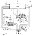
- FIG. 1 is a system configuration diagram of an internal combustion engine equipped with a first embodiment of a control device for an internal combustion engine according to the present invention.
- the block diagram which shows schematically the structure of the humidity sensor shown in FIG. The figure which shows the relationship between the intake-air humidity of an engine, an intake pressure, an intercooler temperature, and the presence or absence of condensed water generation
- the system block diagram which shows the internal structure of the control apparatus (ECU) shown in FIG.
- the block diagram which shows notionally the internal structure of the control apparatus (ECU) shown in FIG.
- the flowchart which shows the control flow of condensed water generation
- the time chart which shows the control content of condensed water generation
- the figure which shows the relationship between an engine EGR rate, an intake pressure, an intercooler temperature, and the presence or absence of condensed water generation
- the system block diagram which shows the internal structure of the control apparatus (ECU) shown in FIG.
- the block diagram which shows notionally the internal structure of the control apparatus (ECU) shown in FIG.
- the flowchart which shows the control flow of condensed water generation
- the time chart which shows the control content of condensed water generation
- FIG. 1 shows a system configuration of an automotive in-cylinder gasoline engine equipped with a first embodiment of a control device for an internal combustion engine (engine) according to the present invention.
- the illustrated engine 100 is, for example, a four-cylinder gasoline engine for automobiles that performs spark ignition combustion.
- An airflow sensor 1 that measures the amount of intake air and a humidity sensor (humidity detection unit) that detects the humidity of the intake air (hereinafter referred to as intake humidity) are located at appropriate positions of the intake pipe 18 that introduces intake air into the combustion chamber of the engine 100.
- an intercooler temperature sensor 8 that measures an intake air temperature immediately after the intercooler is defined as an intercooler temperature
- an electronic control throttle 2 that adjusts an intake pipe pressure
- an intake air pressure hereinafter referred to as an intake manifold pressure
- An intake pressure sensor 14 for measuring the intake pressure).
- the humidity sensor 3 is disposed upstream of the intake pipe 18, and the intake humidity (absolute humidity) detected by the humidity sensor 3 substantially corresponds to the atmospheric humidity (outside air humidity).
- the engine 100 is provided with an injector 13 which is a fuel injection device for injecting fuel into the cylinder 15 and an ignition plug 17 for supplying ignition energy for each cylinder.
- the cylinder head of the engine 100 is provided with a variable valve 5 that adjusts the gas flowing into or out of the cylinder. By adjusting the variable valve 5, for example, all of the first through fourth cylinders are provided. The intake air amount of the cylinder is adjusted.
- a high pressure fuel pump for supplying high pressure fuel to the injector 13 is connected to the injector 13 via a fuel pipe, and a fuel pressure sensor for measuring the fuel injection pressure is connected to the fuel pipe.
- the crankshaft of engine 100 is provided with a crank angle sensor for calculating a rotation angle (not shown).
- a turbine 4b for applying a rotational force to the compressor 4a of the supercharger 4 by exhaust energy
- an electronically controlled waste gate for adjusting the flow rate of the exhaust gas flowing through the turbine 4b.
- a valve 11, a three-way catalyst 10 that purifies the exhaust, and an air-fuel ratio sensor 9 that is an aspect of the air-fuel ratio detector and detects the air-fuel ratio of the exhaust upstream of the three-way catalyst 10 are provided.
- the waste gate valve 11 is disposed in a bypass passage 19 that bypasses the upstream side and the downstream side of the turbine 4b of the turbocharger 4, and the exhaust pipe 16 is adjusted by adjusting the opening degree of the waste gate valve 11.
- a part of the exhaust gas flowing through the engine is shunted, and the amount of exhaust gas flowing into the turbine 4a of the supercharger 4 (exhaust energy) is adjusted.
- the drive state (for example, rotation speed etc.) of supercharger 4 itself is controlled, and the supercharging pressure (namely, intake pressure) by compressor 4a of supercharger 4 is adjusted.
- Signals (detection results) obtained from the air flow sensor 1, the humidity sensor 3, the air-fuel ratio sensor 9, the intercooler temperature sensor 8, and the intake pressure sensor 14 are sent to an engine control unit (ECU: Engine Control Unit) (control device) 20.
- ECU Engine Control Unit
- a signal (detection result) obtained from the accelerator opening sensor 12 is also transmitted to the ECU 20.
- the accelerator opening sensor 12 detects the amount of depression of the accelerator pedal, that is, the accelerator opening.
- the ECU 20 calculates a required torque based on the output signal of the accelerator opening sensor 12. That is, accelerator opening sensor 12 is used as a required torque detection sensor that detects a required torque for engine 100.
- the ECU 20 calculates the rotational speed of engine 100 based on an output signal of a crank angle sensor (not shown).
- the ECU 20 appropriately calculates main operation amounts of the engine 100 such as an air flow rate, a fuel injection amount, an ignition timing, a fuel pressure, and the like based on the operation state of the engine 100 obtained from the output signals of the various sensors described above.
- the ECU 20 transmits the electronic control throttle 2, the injector 13, the spark plug 17, the waste gate valve 11, the intercooler cooling water valve 7 a of the intercooler 7, and the transmission 30 connected to the power shaft of the engine 100. Control etc.
- the fuel injection amount calculated by the ECU 20 is converted into a valve opening pulse signal and transmitted to the injector 13 as an injector drive signal. Further, an ignition signal generated based on the ignition timing is transmitted to the spark plug 17 so that the ignition is calculated at the ignition timing calculated by the ECU 20. Further, the throttle opening calculated by the ECU 20 is transmitted to the electronic control throttle 2 as a throttle drive signal. Further, the operation amount of the variable valve 5 calculated by the ECU 20 is transmitted to the variable valve 5 as a variable valve drive signal. The waste gate valve opening calculated by the ECU 20 is transmitted to the waste gate valve 11 as a waste gate valve drive signal. Further, the intercooler cooling water valve opening calculated by the ECU 20 is transmitted to the intercooler cooling water valve 7a of the intercooler 7 as an intercooler cooling water valve opening driving signal.
- a predetermined amount of fuel is injected from the injector 13 to the air introduced into the cylinder 15 from the intake pipe 18 via the intake valve, and an air-fuel mixture is formed.
- This air-fuel mixture is burned by sparks generated from the spark plug 17 at a predetermined ignition timing, and the piston is pushed down by the combustion pressure to generate the driving force of the engine 100.
- the exhaust gas after combustion is sent to the three-way catalyst 10 through the exhaust pipe 16, and the exhaust components are purified in the three-way catalyst 10 and discharged to the outside.
- FIG. 2 schematically shows the configuration of the humidity sensor shown in FIG.
- the humidity sensor 3 has a positive electrode 3b, a negative electrode 3c, and a moisture sensitive film 3d mounted on a substrate 3a, and the moisture sensitive film 3d is sandwiched between the positive electrode 3b and the negative electrode 3c.
- the humidity sensor 3 becomes a capacitor using the moisture sensitive film 3d as a dielectric, and the relative humidity of the intake air flowing through the intake pipe 18 is detected by a change in the capacitance of the moisture sensitive film 3d as a sensor element. Is done.
- the humidity sensor 3 further includes a temperature detection unit (not shown) so that the absolute humidity can be calculated from the detected relative humidity and temperature.
- FIG. 3 shows the relationship between the intake air humidity, intake air pressure, and intercooler temperature of the engine and the presence or absence of condensed water.
- the water vapor partial pressure in the intake air increases. Then, when the water vapor partial pressure in the intake air exceeds the saturated water vapor partial pressure, the generation of condensed water starts.
- the saturated water vapor pressure is expressed as a function of the atmospheric temperature, that is, the intercooler temperature.
- the intercooler temperature is high, the limit line for the generation of condensed water transitions to the high intake pressure and high intake humidity side, and the intercooler When the temperature is low, the condensate generation limit line shifts to a low intake pressure and low intake humidity side.
- the ECU 20 increases the intake pressure (supercharge) when, for example, the intake humidity (atmosphere humidity) increases, the intake pressure (supercharge pressure) increases, and the water vapor partial pressure in the intake air increases. Pressure) is reduced to reduce the partial pressure of water vapor in the intake air, or the intercooler temperature is raised to change the limit line of condensed water generation to avoid or suppress the generation of condensed water. Further, the ECU 20 suppresses a decrease in torque (output) accompanying a decrease in intake pressure (supercharging pressure) by increasing the engine speed.
- FIG. 4 shows the internal configuration of the control unit (ECU) shown in FIG.
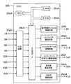
- the ECU 20 mainly includes an input circuit 20a, an input / output port 20b, a RAM 20c, a ROM 20d, and a CPU 20e, and a drive circuit that generates a drive signal for driving each actuator such as the electronic control throttle 2. .
- output signals from the air flow sensor 1, the humidity sensor 3, the intercooler temperature sensor 8, the air-fuel ratio sensor 9, the accelerator opening sensor 12, the intake pressure sensor 14, and the like are input to the input circuit 20a of the ECU 20.
- the input signal is not limited to these.
- the input signal of each sensor input to the input circuit 20a is sent to the input port in the input / output port 20b.
- the signal sent to the input port is stored in the RAM 20c and processed by the CPU 20e.
- the control program describing the contents of the arithmetic processing in the CPU 20e is written in advance in the ROM 20d.
- a value indicating the operation amount of each actuator calculated in accordance with the control program is stored in the RAM 20c and then sent to an output port in the input / output port 20b, and each drive circuit (for example, an electronic control throttle drive circuit 20f, injector drive)
- a circuit 20g, a waste gate valve driving circuit 20h, an intercooler cooling water valve driving circuit 20j, and a transmission driving circuit 20k) are used for each actuator (for example, electronic control throttle 2, injector 13, waste gate valve 11, intercooler 7). It is transmitted as a drive signal to the intercooler cooling water valve 7a and the transmission 30).
- the ECU 20 need not include all of the drive circuits, and may include any one or more of the drive circuits.
- the ECU 20 determines whether condensed water is generated, particularly the intercooler, based on input signals input to the input circuit 20a, particularly input signals input from the humidity sensor 3, the intercooler temperature sensor 8, and the intake pressure sensor 14. 7, whether or not condensed water is generated is determined inside and at the outlet side, and when it is determined that condensed water is generated, the waste gate valve driving circuit 20 h and the intercooler cooling water valve driving circuit 20 j among the above-described driving circuits.
- the waste gate valve 11, the intercooler cooling water valve 7a, and the transmission 30 are controlled via the transmission drive circuit 20k.
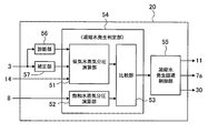
- FIG. 5 conceptually shows the internal structure of the control unit (ECU) shown in FIG.
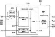
- the ECU 20 mainly includes a condensed water generation determination unit 54 having an intake water vapor partial pressure calculation unit 51, a saturated water vapor partial pressure calculation unit 52, and a comparison unit 53, a condensed water generation avoidance control unit 55, It has.
- the ECU 20 diagnoses an abnormality or failure of the humidity sensor 3 and a correction unit 57 that corrects a detection result (ie, intake humidity) by the humidity sensor 3 based on predetermined information. And.
- An input signal input from the humidity sensor 3 is transmitted to the diagnosis unit 56 and the correction unit 57.
- the diagnosis unit 56 diagnoses an abnormality or failure of the humidity sensor 3 based on the input signal, and transmits the diagnosis result to the intake water vapor partial pressure calculation unit 51 of the condensed water generation determination unit 54.
- the correction unit 57 corrects the input signal (intake humidity detected by the humidity sensor 3) based on information that may affect the intake humidity such as rain or fog, and the correction result is used as a condensed water generation determination unit. 54 to the intake water vapor partial pressure calculation unit 51.
- the correction unit 57 includes information on the external environment of a vehicle such as an automobile on which the engine 100 is mounted, a wiper by a driver (for example, a wiper provided on a windshield of the automobile), and a fog lamp (for example, provided on the front of the automobile).
- Information on the operation of the vehicle such as a fog light
- the intake humidity detected by the humidity sensor 3 is corrected based on the information.
- the influence on intake humidity by rain, fog, etc. can be suppressed.
- the information about the external environment of the vehicle includes a camera mounted in the vehicle interior and outside the vehicle compartment in order to recognize the external environment of the vehicle, and a rain mounted to recognize the rain condition in the vehicle external environment. Sent from a sensor or the like.
- an estimated value of the intake air humidity is calculated from the intake air flow rate introduced into the combustion chamber of the engine 100, the fuel flow rate introduced into the combustion chamber, and the air fuel ratio of the exhaust gas obtained from the air fuel ratio sensor 9.
- the correction unit 57 is input from the humidity sensor 3 based on the estimated value of the intake humidity in order to more precisely correct the input signal (intake humidity detected by the humidity sensor 3) input from the humidity sensor 3. The input signal may be corrected.
- the intake water vapor partial pressure calculation unit 51 calculates the intake water vapor partial pressure during intake based on the correction result of the intake humidity transmitted from the correction unit 57 and the input signal (intake pressure) input from the intake pressure sensor 14. The calculation result is transmitted to the comparison unit 53.
- the intake water vapor partial pressure calculation unit 51 determines that the humidity sensor 3 is abnormal or malfunctioning based on the diagnosis result transmitted from the diagnosis unit 56, the correction of the intake humidity transmitted from the correction unit 57 is performed. Assuming that the result or the intake humidity detected by the humidity sensor 3 is the humidity upper limit value, the intake water vapor partial pressure during intake is calculated. Note that the humidity upper limit value is humidity in a state where water vapor is saturated in the intake air, that is, in a state where the relative humidity is 100%.
- the input signal input from the intercooler temperature sensor 8 is transmitted to the saturated water vapor partial pressure calculating unit 52, and the saturated water vapor partial pressure calculating unit 52 calculates the saturated water vapor partial pressure based on the input signal (intercooler temperature). The calculation result is transmitted to the comparison unit 53.
- the comparison unit 53 compares the intake water vapor partial pressure calculated by the intake water vapor partial pressure calculation unit 51 with the saturated water vapor partial pressure calculated by the saturated water vapor partial pressure calculation unit 52 to determine whether condensed water is generated, The determination result is transmitted to the condensed water generation avoidance control unit 55.
- the condensate generation avoidance control unit 55 determines that the condensate is generated based on the determination result input from the condensate generation determination unit 54, the waste gate valve 11, A control signal is transmitted to the intercooler cooling water valve 7a, the transmission 30 and the like, and the waste gate valve 11 is opened to adjust (lower) the intake pressure (supercharging pressure), and the transmission ratio of the transmission 30 is increased.
- the engine output is maintained, or the intercooler cooling water valve 7a of the intercooler 7 is closed to increase the intake air temperature immediately after the intercooler 7.
- the condensed water generation avoidance control unit 55 determines that the condition is such that no condensed water is generated, the current setting is continued.
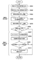
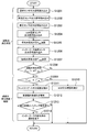
- FIG. 6 specifically shows a control flow for determining condensed water generation and avoiding condensed water generation by the control device (ECU) shown in FIG.
- the control flow shown in FIG. 6 is repeatedly executed by the ECU 20 at a predetermined cycle.
- the diagnosis flow of the abnormality or failure of the humidity sensor 3 by the diagnosis unit 56 and the correction flow of the detection result of the humidity sensor 3 by the correction unit 57 are omitted, and the intake humidity detected by the humidity sensor 3 is omitted. Is transmitted to the intake water vapor partial pressure calculation unit 51 and used for calculating the intake water vapor partial pressure.
- the ECU 20 reads the output signal (intake humidity) of the humidity sensor 3 in step S601, and reads the output signal (intake pressure) of the intake pressure sensor 14 in step S602.
- the ECU 20 uses the following equation (1) from the read output signals of the humidity sensor 3 and the intake pressure sensor 14 in the intake water vapor partial pressure calculation unit 51, and the water vapor partial pressure in the intake air: Calculate P H2O .
- P H2O Intake water vapor partial pressure [Pa]
- P in Intake (supercharging) pressure [Pa]
- H V Intake humidity (absolute volumetric humidity) [g / m 3 ]
- M H2O Molecular weight of water ( ⁇ 18.0) [g / mol]
- P a Intake pipe inlet pressure ( ⁇ atmospheric pressure) [Pa]
- T a Intake pipe inlet temperature ( ⁇ atmospheric temperature) [K]
- R Gas constant [Pa ⁇ m 3 / mol ⁇ K]
- step S603 the intake humidity detected by the humidity sensor 3 is the humidity upper limit value. Then, the intake water vapor pressure P H2O during intake is calculated.
- the ECU 20 reads the output signal (intercooler temperature) of the intercooler temperature sensor 8 in step S604, and in step S605, the saturated water vapor partial pressure calculation unit 52 reads the read output signal of the intercooler temperature sensor 8. From the above, the saturated water vapor partial pressure P ′ H2O is calculated using the following equation (2).
- step S606 the ECU 20 uses the following equation (3) for the intake water vapor partial pressure P H2O calculated in step S603 and the saturated water vapor partial pressure P ′ H2O calculated in step S605 in the comparison unit 53. To determine whether or not the conditions are such that condensed water is generated.
- the ECU 20 determines that the condensate is generated when the above equation (3) is satisfied, and proceeds to step S607. On the other hand, the ECU 20 determines that the condition is such that condensed water is not generated when the above-described equation (3) is not satisfied, that is, when the intake water vapor partial pressure P H2O is equal to or lower than the saturated water vapor partial pressure P ′ H2O . End control.
- step S607 the ECU 20 bypasses the upstream side and the downstream side of the turbine 4b of the turbocharger 4 in order to reduce the intake pressure (supercharging pressure).
- the opening degree of the waste gate valve 11 disposed in the flow path 19 is increased to control the driving state (for example, the rotational speed) of the supercharger 4.
- step S608 the ECU 20 increases the speed of the engine by increasing the gear ratio of the transmission 30 connected to the power shaft of the engine 100 in order to compensate for the output decrease accompanying the decrease in the supercharging pressure.
- step S609 the ECU 20 determines whether or not the ignition timing under the current operating condition is set to the knocking limit point (that is, the trace knocking point), and the ignition timing under the current operating condition is determined to be the knocking limit point. If it is determined that, the series of control is terminated. On the other hand, if the ECU 20 determines that the ignition timing under the current operating conditions is not the knocking limit point, that is, that there is a margin before the occurrence of knocking of the engine 100, in step S610, the ECU 20 increases the intercooler temperature. The opening degree of the intercooler cooling water valve 7a of the cooler 7 is reduced, and the flow rate of the cooling water flowing through the cooling water passage of the intercooler 7 is reduced.
- a heater or the like is provided in the cooling water passage of the intercooler 7, and the temperature of the cooling water flowing through the cooling water passage of the intercooler 7 is controlled by controlling the heater.
- the intercooler temperature may be raised directly.
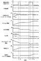
- FIG. 7 shows the contents of control of condensed water generation determination and condensed water generation avoidance by the control device (ECU) shown in FIG. 1 in time series.
- the condensed water generation determination flag atmospheric humidity, water vapor partial pressure downstream of the intercooler (intake water vapor partial pressure and saturated water vapor partial pressure), accelerator opening, waste gate valve opening, intake pressure, transmission ratio (Engine speed), intercooler cooling water valve opening, and intercooler temperature are shown in a time sequence.
- the driver depresses the accelerator pedal and the vehicle accelerates.
- the opening degree of the waste gate valve 11 is decreased and the intake pressure (supercharging pressure) is increased.
- the intake water vapor partial pressure P H2O increases.
- the increased intake water vapor partial pressure P H2O exceeds the integrated value of the saturated water vapor partial pressure P ′ H2O , more specifically, the saturated water vapor partial pressure P ′ H2O and the control ⁇ parameter ⁇ .
- the condensed water determination flag becomes 1.
- the condensate determination flag is set to 1, that is, it is determined that the condensate is generated, as the condensate generation avoidance control, the waste gate valve 11 is opened to reduce the intake pressure (supercharging pressure), and In order to maintain the output, the speed ratio of the transmission 30 is increased to increase the engine speed.
- the opening degree of the intercooler cooling water valve 7a (intercooler cooling) is used to increase the intercooler temperature and shift the condensate generation limit line.
- the water valve opening) is reduced to a predetermined value.
- the intercooler temperature after a certain time and thus reduce the intercooler cooling water valve opening has elapsed, it rises with a certain time delay which is namely (in the illustrated example, the time t D after).
- the intake water vapor partial pressure P H2O falls below the saturated water vapor partial pressure P ′ H2O , more specifically, the integrated value of the saturated water vapor partial pressure P ′ H2O and the parameter ⁇ , and the condensed water determination flag is 0 again. Therefore, after that, the waste gate valve opening and the gear ratio are kept substantially constant while the accelerator opening is constant.
- intercooler temperature begins to rise with a delay, with an increase in the intercooler temperature, as described with reference to FIG. 3, the limit line condensed water is generated is changed into the high intake pressure side Therefore, in order to increase the intake pressure, the waste gate valve opening is decreased, and the gear ratio of the transmission 30 is decreased accordingly.
- the control device of the first embodiment in the engine 100 including the supercharger 30, whether or not condensed water is generated based on the intake humidity detected by the humidity sensor 3 disposed in the intake pipe 18. And controlling the driving state of the supercharger 30 based on the determination result, adjusting the intake pressure (supercharging pressure), and performing the condensed water generation avoidance control, for example, under conditions where the atmospheric humidity is high Even underneath, generation of condensed water in the intercooler or downstream thereof can be effectively avoided, and damage to the engine, corrosion of the intake pipe, and deterioration of operability can be suppressed.
- the intake water vapor partial pressure immediately after the intercooler 7 calculated based on the intake air humidity detected by the humidity sensor 3, the intake air pressure downstream of the compressor 4 a of the supercharger 4 detected by the intake air pressure sensor 14, etc.
- the presence or absence of condensed water is determined. Presence or absence of occurrence can be determined precisely to effectively suppress the generation of condensed water.
- the driving state of the supercharger 30 is increased by increasing the speed of the engine 30 by increasing the gear ratio of the transmission 30 connected to the power shaft of the engine 100. Even when the intake pressure (supercharging pressure) is reduced by control, it is possible to secure engine torque (output) and suppress a decrease in drivability.
- the control device of the second embodiment shown in FIGS. 8 to 13 is configured to control the low pressure EGR system provided in the internal combustion engine with respect to the control device of the first embodiment shown in FIGS.
- the other configurations are the same as those of the control device of the first embodiment. Therefore, the same components as those in the first embodiment are denoted by the same reference numerals, and detailed description thereof is omitted.
- FIG. 8 shows a system configuration of an in-cylinder injection gasoline engine for automobiles having a low pressure EGR system in which a second embodiment of the control device for an internal combustion engine (engine) according to the present invention is mounted.
- engine 100A shown in FIG. 8 is downstream of humidity sensor 3A provided in intake pipe 18A from the downstream side of three-way catalyst 10A provided in exhaust pipe 16A.
- a low pressure EGR system having an EGR pipe 40A for recirculating part of the exhaust gas on the upstream side of the compressor 4aA of the supercharger 4A.
- EGR gas flowing through the EGR pipe 40A is disposed at an appropriate position of the EGR pipe 40A connecting the exhaust pipe 16A downstream of the turbine 4bA of the turbocharger 4A and the intake pipe 18A upstream of the compressor 4aA of the supercharger 4A.
- EGR cooler 42A for cooling (exhaust), EGR valve 41A for controlling EGR gas flow rate (EGR flow rate), and differential pressure before and after EGR valve 41A (EGR valve differential pressure before and after) are detected to detect EGR flow rate.
- a differential pressure sensor (EGR flow rate detection unit) 43A that measures the EGR temperature, and an EGR temperature sensor (EGR temperature detection unit) 44A that detects the temperature of the EGR gas (EGR temperature) are attached.
- Signals (detection results) obtained from the air flow sensor 1A, the humidity sensor 3A, the air-fuel ratio sensor 9A, the intercooler temperature sensor 8A, the intake pressure sensor 14A, the differential pressure sensor 43A, and the EGR temperature sensor 44A are sent to the ECU (control device) 20A.
- a signal (detection result) obtained from the accelerator opening sensor 12A is also transmitted to the ECU 20A.
- ECU 20A calculates the required torque based on the output signal of accelerator opening sensor 12A, and calculates the rotational speed of engine 100A based on the output signal of a crank angle sensor (not shown).
- the ECU 20A appropriately calculates main operating amounts of the engine 100A such as the air flow rate, the fuel injection amount, the ignition timing, the fuel pressure, etc. based on the operating state of the engine 100A obtained from the output signals of the various sensors described above.
- the ECU 20A Based on the calculation result, the ECU 20A, as in the first embodiment, the electronic control throttle 2A, the injector 13A, the ignition plug 17A, the wastegate valve 11A, the intercooler cooling water valve 7aA of the intercooler 7A, and the engine 100A
- the transmission 30A and the like connected to the power shaft are controlled, and the EGR valve 41A attached to the EGR pipe 40A is controlled. That is, the throttle opening degree calculated by the ECU 20A is transmitted as a drive signal to the electronic control throttle 2, etc., and the EGR valve opening degree calculated by the ECU 20A is transmitted to the EGR valve 41A as an EGR valve opening degree drive signal. .
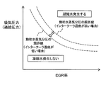
- FIG. 9 shows the relationship between the EGR rate of the engine, the intake pressure, the intercooler temperature, and whether or not condensed water is generated.
- the EGR rate representing the ratio of EGR gas in the intake air and the intake pressure (supercharging pressure) detected by the intake pressure sensor 14A increase, the water vapor partial pressure in the intake air increases. Then, when the water vapor partial pressure in the intake air exceeds the saturated water vapor partial pressure, the generation of condensed water starts.
- the saturated water vapor pressure is expressed as a function of the atmospheric temperature, that is, the intercooler temperature. When the intercooler temperature is high, the limit line for the generation of condensed water transitions to the high intake pressure and high EGR rate side, and the intercooler When the temperature is low, the condensate generation limit line shifts to a low intake pressure and low EGR rate side.
- the ECU 20A decreases the EGR rate when the intake humidity (atmospheric humidity) increases, the intake pressure (supercharging pressure) increases, and the water vapor partial pressure during intake increases. Reduce or reduce the intake water pressure (supercharging pressure) to reduce the partial pressure of water vapor in the intake air, or increase the intercooler temperature to change the condensate generation limit line. To do. Further, the ECU 20A suppresses a decrease in torque (output) accompanying a decrease in intake pressure (supercharging pressure) by increasing the engine speed.
- the relationship between the engine intake humidity, the intake pressure, the intercooler temperature, and whether or not condensed water is generated is the same as that shown in FIG.
- FIG. 10 shows the internal configuration of the control unit (ECU) shown in FIG.
- the ECU 20A shown in FIG. 10 includes an EGR valve drive circuit 20mA that generates a drive signal for driving the EGR valve 41A in addition to the components of the ECU 20 shown in FIG.
- output signals from the air flow sensor 1A, the humidity sensor 3A, the intercooler temperature sensor 8A, the air-fuel ratio sensor 9A, the accelerator opening sensor 12A, the intake pressure sensor 14A, and the like are output from the ECU 20A.
- output signals of the differential pressure sensor 43A and the EGR temperature sensor 44A are input to the input circuit 20aA of the ECU 20A.
- the input signal of each sensor input to the input circuit 20aA is sent to the input port in the input / output port 20bA.
- the signal sent to the input port is stored in the RAM 20cA and processed by the CPU 20eA.
- the control program describing the contents of the arithmetic processing in the CPU 20eA is written in advance in the ROM 20dA.
- a value indicating the operation amount of each actuator calculated in accordance with the control program is stored in the RAM 20cA and then sent to the output port in the input / output port 20bA, where each drive circuit (for example, electronic control throttle drive circuit 20fA, injector drive) A circuit 20gA, a waste gate valve drive circuit 20hA, an intercooler cooling water valve drive circuit 20jA, a transmission drive circuit 20kA, an EGR valve drive circuit 20mA, and the like (for example, electronic control throttle 2A, injector 13A, waste gate valve) 11A, the intercooler cooling water valve 7aA of the intercooler 7A, the transmission 30A, and the EGR valve 41A) are transmitted as drive signals.
- each drive circuit for example, electronic control throttle drive circuit 20fA, injector drive
- the ECU 20A determines whether condensed water is generated, particularly the intercooler, based on input signals input to the input circuit 20aA, particularly input signals input from the humidity sensor 3A, the intercooler temperature sensor 8A, and the intake pressure sensor 14A.
- the waste gate valve driving circuit 20hA and the intercooler cooling water valve driving circuit 20jA among the above-described driving circuits.
- the waste gate valve 11A, the intercooler cooling water valve 7aA, the transmission 30A, and the EGR valve 41A are controlled via the transmission drive circuit 20kA and the EGR valve drive circuit 20mA.
- FIG. 11 conceptually shows the internal structure of the control unit (ECU) shown in FIG. 11, ECU 20A, like ECU 20 shown in FIG. 5, has a diagnostic unit 56A, a correction unit 57A, an intake water vapor partial pressure calculation unit 51A, a saturated water vapor partial pressure calculation unit 52A, and a comparison unit 53A.
- a determination unit 54A and a condensed water generation avoidance control unit 55A are provided.
- An input signal input from the humidity sensor 3A is transmitted to the diagnosis unit 56A and the correction unit 57A.
- the diagnosis unit 56A diagnoses an abnormality or failure of the humidity sensor 3A based on the input signal, and transmits the diagnosis result to the intake water vapor partial pressure calculation unit 51A of the condensed water generation determination unit 54A.
- the correction unit 57A receives the input signal (based on information such as rain or fog that may affect the intake humidity, an estimated value of the intake humidity calculated from the intake flow rate introduced into the combustion chamber of the engine 100A, etc.) (Intake humidity detected by the humidity sensor 3A) is corrected, and the correction result is transmitted to the intake water vapor partial pressure calculation unit 51A of the condensed water generation determination unit 54A.
- the correction unit 57A is The input signal input from the humidity sensor 3A without correction. That is, in the correction unit 57A, the flow rate of the EGR gas flowing through the EGR pipe 40A is not more than a predetermined value (the EGR gas is not flowing through the EGR pipe 40A, or the flow rate of the EGR gas is extremely small (for example, the EGR rate is 3%). Only)), the input signal input from the humidity sensor 3A may be corrected and transmitted to the intake water vapor partial pressure calculation unit 51A.
- the intake water vapor partial pressure calculation unit 51A includes the correction result of the intake humidity transmitted from the correction unit 57A and the input signals (intake pressure, difference before and after the EGR valve) input from the intake pressure sensor 14A, the differential pressure sensor 43A, and the EGR temperature sensor 44A. Pressure, EGR temperature), the intake water vapor partial pressure in the intake air is calculated, and the calculation result is transmitted to the comparison unit 53A.
- the intake water vapor partial pressure calculation unit 51A determines that the humidity sensor 3A is abnormal or malfunctioning based on the diagnosis result transmitted from the diagnosis unit 56A, the correction of the intake humidity transmitted from the correction unit 57A. Assuming that the intake humidity detected by the result or the humidity sensor 3A is the humidity upper limit value, the intake water vapor partial pressure during the intake is calculated.
- the input signal input from the intercooler temperature sensor 8A is transmitted to the saturated water vapor partial pressure calculating unit 52A, and the saturated water vapor partial pressure calculating unit 52A calculates the saturated water vapor partial pressure based on the input signal (intercooler temperature). The calculation result is transmitted to the comparison unit 53A.
- the comparison unit 53A compares the intake water vapor partial pressure calculated by the intake water vapor partial pressure calculation unit 51A with the saturated water vapor partial pressure calculated by the saturated water vapor partial pressure calculation unit 52A. The presence or absence of condensed water generation is determined, and the determination result is transmitted to the condensed water generation avoidance control unit 55A.
- the condensate water generation avoidance control unit 55A determines that the condensate is generated based on the determination result input from the condensate generation determination unit 54A, the waste gate valve 11A, A control signal is transmitted to the intercooler cooling water valve 7aA, the transmission 30A, the EGR valve 41A, etc., and the waste gate valve 11A is opened to adjust (lower) the intake pressure (supercharging pressure), and the transmission of the transmission 30A
- the engine output is maintained by increasing the ratio, the intercooler cooling water valve 7aA of the intercooler 7A is closed to increase the intake air temperature immediately after the intercooler 7A, or the EGR valve 41A is closed to decrease the EGR rate.
- the condensate generation avoidance control unit 55A determines that the condition is such that no condensate is generated, the current setting is continued.
- FIG. 12 specifically shows a control flow for determination of condensed water generation and avoidance of condensed water generation by the control device (ECU) shown in FIG.
- the control flow shown in FIG. 12 is repeatedly executed at a predetermined cycle by the ECU 20A.
- the diagnosis flow of the abnormality or failure of the humidity sensor 3A by the diagnosis unit 56A and the correction flow of the detection result of the humidity sensor 3A by the correction unit 57A are omitted, and the intake air humidity detected by the humidity sensor 3A is omitted. Is transmitted to the intake water vapor partial pressure calculating unit 51A and used for calculating the intake water vapor partial pressure.
- the ECU 20A reads the output signal (intake humidity) of the humidity sensor 3A in step S1201, reads the output signal (intake pressure) of the intake pressure sensor 14A in step S1202, and outputs the output of the differential pressure sensor 43A in step S1203.
- a signal (differential pressure before and after the EGR valve) is read, and in step S1204, an output signal (EGR temperature) of the EGR temperature sensor 44A is read.
- the ECU 20A uses the following expression (4) from the output signals of the humidity sensor 3A, the intake pressure sensor 14A, the differential pressure sensor 43A, and the EGR temperature sensor 44A read by the intake water vapor partial pressure calculation unit 51A. ) To calculate the water vapor partial pressure P H2O in the intake air.
- EGR rate ⁇ EGR and the volumetric absolute humidity HV_EGR of water vapor in EGR are obtained using the following equations (5) and (6), respectively.
- the ECU 20A reads an output signal (intercooler temperature) of the intercooler temperature sensor 8A in step S1206, and in step S1207, the saturated water vapor partial pressure calculation unit 52A reads the output signal of the intercooler temperature sensor 8A. From the above, the saturated water vapor partial pressure P ′ H 2 O is calculated using the above-described equation (2).
- step S1208 the ECU 20A uses the above equation (3) for the intake water vapor partial pressure P H2O calculated in step S1205 and the saturated water vapor partial pressure P ′ H2O calculated in step S1207 in the comparison unit 53A. To determine whether or not the conditions are such that condensed water is generated.
- the ECU 20A determines that the condition is such that condensed water is generated when the above-described equation (3) is satisfied, and proceeds to step S1209. On the other hand, the ECU 20A determines that the condition is such that condensed water is not generated when the above-described equation (3) is not satisfied, that is, when the intake water vapor partial pressure P H2O is equal to or lower than the saturated water vapor partial pressure P ′ H2O . End control.
- the ECU 20A determines that the condition is that condensate is generated, in step S1209, the ECU 20A calculates the following equation (7) in order to determine the possibility of reducing the EGR rate ⁇ EGR from the viewpoint of the exhaust temperature limit, the knocking limit, and the like. It is used to determine whether or not the current EGR rate ⁇ EGR is equal to or less than the EGR rate ⁇ LIM that is the operation limit.
- the EGR rate ⁇ LIM that is the operation limit is set in advance from the viewpoint of, for example, the exhaust temperature limit and the knocking limit, and is stored in the ECU 20A for each operation condition.
- ECU 20A determines that the EGR rate cannot be decreased any more and proceeds to step S1211. On the other hand, the ECU 20A proceeds to step S1210 when the above-described formula (7) is not satisfied, that is, when the current EGR rate ⁇ EGR is larger than the EGR rate ⁇ LIM that is the operation limit, and the EGR rate is decreased to reduce the EGR rate. The opening degree of the valve 41A is decreased, and a series of control is finished.
- the ECU 20A determines that the condensed water is generated and that the EGR rate cannot be further reduced, the ECU 20A performs the same as in steps S607 to S610 (see FIG. 6) of the first embodiment, in step S1211.
- the opening state of the waste gate valve 11A is increased to control the driving state (for example, the rotational speed) of the supercharger 4A.
- the ECU 20A increases the speed of the engine by increasing the gear ratio of the transmission 30A in order to compensate for the output decrease accompanying the decrease in the supercharging pressure.
- step S1213 the ECU 20A determines whether or not the ignition timing under the current operating condition is set to the knocking limit point (that is, the trace knocking point), and the ignition timing under the current operating condition is determined to be the knocking limit point. If it is determined that, the series of control is terminated. On the other hand, if ECU 20A determines that the ignition timing under the current operating conditions is not the knock limit point, that is, that there is room before knocking of engine 100A occurs, in step S1214, in order to increase the intercooler temperature, The opening degree of the intercooler cooling water valve 7aA of the cooler 7A is reduced, and the flow rate of the cooling water flowing through the cooling water passage of the intercooler 7A is reduced.
- the knocking limit point that is, the trace knocking point
- a heater or the like is provided in the cooling water passage of the intercooler 7A, and the temperature of the cooling water flowing through the cooling water passage of the intercooler 7A is controlled by controlling the heater.
- the intercooler temperature may be raised directly.
- FIG. 13 shows, in a time series, the control contents of the condensed water generation determination and the condensed water generation avoidance by the control device (ECU) shown in FIG.
- the opening degree, the intake pressure, and the gear ratio (engine speed) are shown in a time sequence.
- the driver depresses the accelerator pedal in two stages and the vehicle accelerates in two stages.
- the opening degree of the waste gate valve 11A (the waste gate valve opening degree) is decreased, the intake pressure (supercharging pressure) is increased, and accordingly, the downstream of the intercooler 7A.
- the intake water vapor partial pressure P H2O increases.
- Condensed water determination flag is 1, i.e. when it is determined that the condition for the condensed water is generated, as condensed water generation avoidance control, firstly, to reduce the EGR rate gamma EGR, the EGR valve 41A opening (EGR Decrease the valve opening.
- EGR rate ⁇ EGR is larger than the EGR rate ⁇ LIM which is the operation limit.
- the accelerator depression amount by the driver becomes substantially constant, the intake vapor partial pressure P H2 O saturated water vapor pressure P by reduction of the EGR rate 'H2 O, and more specifically the saturated water vapor pressure P' H2 O and parameters Below the integrated value with ⁇ , the condensed water determination flag returns to 0 again. Therefore, after that, the EGR valve opening and the waste gate valve opening are kept substantially constant while the accelerator opening is constant.
- the acceleration operation by the accelerator depression of the driver is started again, the waste gate valve opening is reduced, and the increased intake water vapor partial pressure P H2O is saturated with the water vapor partial pressure P ′ H2O , more specifically, saturation.
- the condensed water determination flag is set to 1 again after exceeding the integrated value of the water vapor partial pressure P ′ H2O and the parameter ⁇ relating to the control margin.
- the condensed water determination flag becomes 1, first, the EGR valve opening is decreased in order to decrease the EGR rate ⁇ EGR as described above.
- the EGR rate ⁇ EGR is decreased from the viewpoint of knockability and reduced operability due to air volume fluctuations. I can't. Therefore, with the EGR valve opening degree kept substantially constant, the waste gate valve 11A is opened to reduce the intake pressure (supercharging pressure), and the transmission ratio of the transmission 30A is increased to maintain the output. Increase engine speed.
- the intake water vapor partial pressure P H2O is reduced to the saturated water vapor partial pressure P ′ H2O , more specifically, the integrated value of the saturated water vapor partial pressure P ′ H2O and the parameter ⁇ due to a decrease in the intake pressure (supercharging pressure). Since the condensed water determination flag returns to 0 again, the waste gate valve opening is kept substantially constant thereafter.
- the embodiment in which the control for increasing the intercooler temperature is not performed on the assumption that the ignition timing is set to the knocking limit point is described. However, the ignition timing is set to the knocking limit point. If not, as described with reference to FIG. 7, the intercooler cooling water valve opening is decreased, or the temperature of the cooling water flowing through the cooling water passage of the intercooler is directly increased to increase the intercooler temperature. Also good.
- the condensation is performed based on the intake humidity detected by the humidity sensor 3A disposed in the intake pipe 18A.
- the presence or absence of water generation is determined, and based on the determination result, the driving state of the supercharger 30A, the opening degree of the EGR valve 41A, etc. are controlled, and the intake pressure (supercharging pressure) is adjusted to control the generation of condensed water.
- the presence or absence of condensed water is determined by comparing the water vapor partial pressure of the intake air immediately after the intercooler 7A with the saturated water vapor partial pressure in the intake air immediately after the intercooler 7A.
- the flow rate of the EGR gas flowing through the EGR pipe 40A is reduced by controlling the opening degree of the EGR valve 41A, and the intake pressure is adjusted by controlling the driving state of the supercharger 4A after the flow rate of the EGR gas reaches the lower limit value.
- Condensed water generation avoidance control can be quickly suppressed, and condensate water generation can be achieved while suppressing deterioration of operability such as knocking and air volume fluctuations associated with a decrease in EGR gas flow rate. Can be effectively suppressed.
- the EGR gas flowing through the EGR pipe 40A is returned to the downstream side of the humidity sensor 3A and the upstream side of the compressor 4aA of the supercharger 4A. That is, the humidity sensor 3A is connected to the EGR pipe 40A.
- the humidity sensor 3A detects the humidity of the intake air before being connected to the intake pipe 18A. From the output signals of the sensor 3A, the intake pressure sensor 14A, the differential pressure sensor 43A, and the EGR temperature sensor 44A, the water vapor partial pressure P H2O in the intake air was calculated.
- the EGR gas flowing through the EGR pipe 40A is recirculated to the upstream side of the humidity sensor 3A, that is, the humidity sensor 3A is more than the connection point between the EGR pipe 40A and the intake pipe 18A.
- the humidity sensor 3A is From the output signal of the intake pressure sensor 14A, the water vapor partial pressure PH2O during intake can be calculated.
- the supercharger is controlled by controlling the opening degree of the waste gate valve disposed in the bypass flow path that bypasses the upstream side and the downstream side of the turbocharger turbine.
- the driving state of the supercharger may be controlled by a method other than the control of the opening degree of the waste gate valve, for example, by switching the number of stages of the supercharger. Of course it is good.
- the present invention is not limited to the first and second embodiments described above, and includes various modifications.
- the first and second embodiments described above have been described in detail for easy understanding of the present invention, and are not necessarily limited to those having all the configurations described.
- a part of the configuration of an embodiment can be replaced with the configuration of another embodiment, and the configuration of another embodiment can be added to the configuration of an embodiment.
- control lines and information lines indicate what is considered necessary for the explanation, and not all the control lines and information lines on the product are necessarily shown. Actually, it may be considered that almost all the components are connected to each other.
Landscapes
- Engineering & Computer Science (AREA)
- Chemical & Material Sciences (AREA)
- Combustion & Propulsion (AREA)
- Mechanical Engineering (AREA)
- General Engineering & Computer Science (AREA)
- Supercharger (AREA)
- Combined Controls Of Internal Combustion Engines (AREA)
- Exhaust-Gas Circulating Devices (AREA)
- Output Control And Ontrol Of Special Type Engine (AREA)
- Control Of Vehicle Engines Or Engines For Specific Uses (AREA)
Abstract
過給機を備えた内燃機関における凝縮水の発生を確実に抑制することのできる内燃機関の制御装置を提供することにある。制御装置(20)は、内燃機関(100)の燃焼室に導入される吸気の湿度に基づき吸気を過給する過給機(4)の駆動状態を制御して吸気の圧力を調整する。また、制御装置(20)は、吸気の圧力を調整すると共に、インタークーラ下流の吸気の温度を上昇させたり、変速機の変速比を増加させる。
Description
本発明は、内燃機関の制御装置に係り、例えば過給機を備えた内燃機関の制御装置に関する。
従来から、自動車等の車両の燃費低減技術の一つとして、圧縮比を高くしてエンジン(内燃機関)の理論熱効率を向上させる技術(エンジンの高圧縮比化)が知られている。また、他の燃費低減技術として、エンジンのダウンサイジング化も知られており、このダウンサイジング化によってポンピングロスや機械損失を低減させることができる。
しかしながら、ダウンサイジングしたエンジンにおいては、トルク(出力)を維持するために過給圧力を上昇させる必要があり、過給圧力を上昇させると、それに応じて過給機のコンプレッサ下流の吸気の温度(以下、吸気温度という)が上昇する。このような吸気温度の上昇は、エンジンのノッキングやプレイグニッションと呼ばれる異常燃焼の発生に繋がるため、過給機を備えたエンジンでは、吸気中にインタークーラを配設し、該インタークーラにより吸気を冷却した後に燃焼室に導入することが提案されている。従って、エンジンの最大過給圧力を上昇させると、それに応じてインタークーラにおける冷却量が増加し、インタークーラ内もしくはその下流において吸気の凝縮水が発生する可能性がある。そして、この凝縮水が吸気の流れによってエンジンの燃焼室に導入されると、ウォーターハンマ等の発生によりエンジンが破損するといった問題が生じ得る。
なお、上記した凝縮水は、大気中に存在する水蒸気の分圧が飽和水蒸気圧を超えて凝縮することで生成される液体であり、このような凝縮水は、大気中に存在する水蒸気の分圧が高い、すなわち大気の湿度が高いほど発生し易いことが知られている。
また、高過給のエンジンでは、異常燃焼の発生を回避するために、排気の一部を吸気に戻すEGR(Exhaust Gas Recirculation)システムの導入が進められている。特に、近年では、過給領域においても大量のEGRガスを循環させ得る低圧EGRシステムが着目されている。この低圧EGRシステムは、過給機のタービン下流の排気を過給機のコンプレッサ上流に還流するシステムであり、EGRガスは排気そのものであるため、燃焼によって生成された多くの水蒸気を含んでいる。この低圧EGRシステムでは、一般に空気よりも水蒸気量の多いEGRガスと空気とが混合されて生成された混合気がコンプレッサにより圧縮され、その後にインタークーラで冷却されるため、前述した凝縮水が発生し易いといった問題が生じ得る。また、この凝縮水には、上記したように腐食性のある排気成分の一部が混入するため、インタークーラや吸気管が腐食して破損する可能性があるといった問題も生じ得る。
このような問題に対し、特許文献1には、吸気管に設けられたインタークーラの出口側吸気での凝縮水の生成を防止する技術が開示されている。
特許文献1に開示されている内燃機関は、車両に搭載され、吸気管に走行風と吸気とを熱交換させて吸気を冷却するインタークーラを備えた内燃機関において、インタークーラの上流側吸気温度を検出する上流側吸気温度検出手段と、インタークーラの上流側吸気湿度を検出する上流側吸気湿度検出手段と、インタークーラに配設され、インタークーラに当る走行風量を調節する開度調節可能なシャッタ装置と、上流側吸気温度検出手段及び上流側吸気湿度検出手段の検出値から吸気の水蒸気分圧を算出し、インタークーラ出口側吸気温度が水蒸気分圧を飽和水蒸気分圧とする温度以上となるようにシャッタ装置の作動を制御するコントローラと、を備えているものである。
しかしながら、特許文献1に開示されている内燃機関においては、インタークーラに当る走行風量を調節する開度調節可能なシャッタ装置の作動を制御してインタークーラ出口側吸気温度を調整するため、例えばインタークーラ出口側吸気温度を上昇させるのに時間を要し、応答性が低く、インタークーラの出口側吸気で過渡的に凝縮水が発生し得るといった課題があった。
本発明は、前記問題に鑑みてなされたものであって、その目的とするところは、過給機を備えた内燃機関における凝縮水の発生を確実に抑制することのできる内燃機関の制御装置を提供することにある。
上記する課題を解決するために、本発明に係る内燃機関の制御装置は、燃焼室に導入される吸気の湿度を検出する湿度検出部と前記吸気を過給する過給機とを備えた内燃機関の制御装置であって、前記制御装置は、前記吸気の湿度に基づき前記過給機の駆動状態を制御して前記吸気の圧力を調整することを特徴とする。
以上の説明から理解できるように、本発明によれば、湿度検出部により検出される吸気の湿度に基づき過給機の駆動状態を制御し、吸気の圧力(過給圧力)を調整して吸気の水蒸気分圧を調整することにより、吸気中の水蒸気分圧を応答性良く制御することができ、吸気中における凝縮水の発生を確実に抑制することができる。
上記した以外の課題、構成及び効果は、以下の実施形態の説明により明らかにされる。
以下、本発明に係る内燃機関の制御装置の実施形態を図面を参照して説明する。
[第1実施形態]
まず、図1~図7を参照して、本発明に係る内燃機関の制御装置の第1実施形態の構成及び動作について説明する。
まず、図1~図7を参照して、本発明に係る内燃機関の制御装置の第1実施形態の構成及び動作について説明する。
図1は、本発明に係る内燃機関(エンジン)の制御装置の第1実施形態が搭載された自動車用筒内噴射式ガソリンエンジンのシステム構成を示したものである。
図示するエンジン100は、例えば、火花点火式燃焼を実施する自動車用の4気筒ガソリンエンジンである。エンジン100の燃焼室に吸気を導入する吸気管18の適宜位置には、吸入空気量を計測するエアフローセンサ1と、吸気の湿度(以下、吸気湿度という)を検出する湿度センサ(湿度検出部)3と、吸気を過給するための過給機4のコンプレッサ4aと、コンプレッサ4a下流で過給後の吸気を冷却するためのインタークーラ7と、インタークーラ直後の吸気の温度(以下、吸気温度といい、特にインタークーラ直後の吸気温度をインタークーラ温度と規定する)を計測するインタークーラ温度センサ8と、吸気管圧力を調整する電子制御スロットル2と、吸気マニホールド6内の吸気の圧力(以下、吸気圧力という)を計測する吸気圧力センサ14と、が備えられている。なお、湿度センサ3は、吸気管18のうちで上流側に配設されており、該湿度センサ3によって検出される吸気湿度(絶対湿度)は、大気湿度(外気湿度)にほぼ相当する。
また、エンジン100には、各気筒毎に、シリンダ15の内部に燃料を噴射する燃料噴射装置であるインジェクタ13と点火エネルギを供給する点火プラグ17とが備えられている。また、エンジン100のシリンダヘッドには、気筒内に流入又は気筒内から排出するガスを調整する可変バルブ5が備えられ、この可変バルブ5を調整することにより、例えば1番から4番までの全気筒の吸気量が調整される。また、インジェクタ13には、該インジェクタ13に高圧燃料を供給するための高圧燃料ポンプが燃料配管を介して接続されており、この燃料配管には、燃料噴射圧力を計測するための燃料圧力センサが備えられている(不図示)。さらに、エンジン100のクランク軸には、回転角度を算出するためのクランク角度センサが備えられている(不図示)。
エンジン100の排気管16の適宜位置には、排気エネルギによって過給機4のコンプレッサ4aに回転力を与えるためのタービン4bと、このタービン4bに流れる排気の流量を調整するための電子制御ウェイストゲート弁11と、排気を浄化する三元触媒10と、空燃比検出器の一態様であって三元触媒10の上流側で排気の空燃比を検出する空燃比センサ9と、が備えられる。ウェイストゲート弁11は、過給機4のタービン4bの上流側と下流側とをバイパスするバイパス流路19に配設され、このウェイストゲート弁11の開度が調整されることで、排気管16を流れる排気ガスの一部が分流され、過給機4のタービン4aへの排気ガスの流入量(排気エネルギ)が調整される。これにより、過給機4自体の駆動状態(例えば、回転数等)が制御されて、過給機4のコンプレッサ4aによる過給圧力(すなわち、吸気圧力)が調整される。
エアフローセンサ1と湿度センサ3と空燃比センサ9とインタークーラ温度センサ8と吸気圧力センサ14とから得られる信号(検出結果)は、エンジンコントロールユニット(ECU:Engine Control Unit)(制御装置)20に送信されると共に、アクセル開度センサ12から得られる信号(検出結果)もECU20に送信される。なお、アクセル開度センサ12は、アクセルペダルの踏み込み量、すなわち、アクセル開度を検出するものである。ECU20は、アクセル開度センサ12の出力信号に基づいて要求トルクを演算する。すなわち、アクセル開度センサ12は、エンジン100への要求トルクを検出する要求トルク検出センサとして用いられる。また、ECU20は、不図示のクランク角度センサの出力信号に基づいて、エンジン100の回転速度を演算する。ECU20は、上記した各種センサの出力信号等から得られるエンジン100の運転状態に基づいて、空気流量、燃料噴射量、点火時期、燃料圧力等といったエンジン100の主要な作動量を適正に演算する。
ECU20は、その演算結果に基づいて、電子制御スロットル2、インジェクタ13、点火プラグ17、ウェイストゲート弁11、インタークーラ7のインタークーラ冷却水弁7a、エンジン100の動力軸に連結された変速機30等を制御する。
例えば、ECU20で演算された燃料噴射量は開弁パルス信号に変換され、インジェクタ駆動信号としてインジェクタ13に送信される。また、ECU20で演算された点火時期で点火されるように、その点火時期に基づき生成される点火信号が点火プラグ17に送信される。また、ECU20で演算されたスロットル開度は、スロットル駆動信号として電子制御スロットル2に送信される。また、ECU20で演算された可変バルブ5の作動量は、可変バルブ駆動信号として可変バルブ5へ送信される。また、ECU20で演算されたウェイストゲート弁開度は、ウェイストゲート弁駆動信号としてウェイストゲート弁11へ送信される。さらに、ECU20で演算されたインタークーラ冷却水弁開度は、インタークーラ冷却水弁開度駆動信号としてインタークーラ7のインタークーラ冷却水弁7aへ送信される。
吸気管18から吸気バルブを介してシリンダ15内に導入された空気に対し、インジェクタ13から所定量の燃料が噴射されて混合気が形成される。この混合気は、所定の点火時期で点火プラグ17から発生される火花により燃焼され、その燃焼圧によりピストンが押し下げられてエンジン100の駆動力が生成される。燃焼後の排気ガスは、排気管16を介して三元触媒10に送られ、その排気成分が三元触媒10内で浄化されて外部へ排出される。
図2は、図1に示す湿度センサの構成を概略的に示したものである。
図示するように、湿度センサ3は、基板3a上に正電極3bと負電極3cと感湿膜3dとが実装され、正電極3bと負電極3cとによって感湿膜3dが挟持されている。このような構成により、湿度センサ3は、感湿膜3dを誘電体としたコンデンサとなり、センサ素子である感湿膜3dの静電容量の変化によって、吸気管18を流れる吸気の相対湿度が検出される。また、この湿度センサ3は不図示の温度検出部を更に備えており、検出した相対湿度および温度から絶対湿度を演算できるようになっている。
図3は、エンジンの吸気湿度、吸気圧力、及びインタークーラ温度と、凝縮水発生の有無との関係を示したものである。
湿度センサ3および吸気圧力センサ14によって検出される吸気湿度(絶対湿度)および吸気圧力(過給圧力)が高くなるに従って、吸気中の水蒸気分圧は上昇する。そして、その吸気中の水蒸気分圧が飽和水蒸気分圧を超過すると、凝縮水の発生が開始することとなる。ここで、飽和水蒸気圧は、雰囲気温度、すなわちインタークーラ温度の関数として表され、インタークーラ温度が高い場合は、凝縮水発生の限界線が高吸気圧力かつ高吸気湿度側に遷移し、インタークーラ温度が低い場合は、凝縮水発生の限界線が低吸気圧力かつ低吸気湿度側に遷移する。
このように、吸気湿度が高い、吸気圧力(過給圧力)が高い、あるいはインタークーラ温度が低い場合に、凝縮水が発生し易いことから、この凝縮水の発生を回避もしくは抑制するためには、ECU20により、吸気湿度を減少させる、吸気圧力(過給圧力)を減少させる、あるいはインタークーラ温度を上昇させるように制御することが有効であると考えられる。そこで、本第1実施形態では、ECU20は、例えば吸気湿度(大気湿度)が高くなったり、吸気圧力(過給圧力)が高くなり、吸気中の水蒸気分圧が上昇すると、吸気圧力(過給圧力)を減少させて吸気中の水蒸気分圧を減少させる、あるいは、インタークーラ温度を上昇させて凝縮水発生の限界線を変化させるようにして凝縮水の発生を回避もしくは抑制する。また、ECU20は、エンジン回転数を上昇させるようにして吸気圧力(過給圧力)の減少に伴うトルク(出力)低下を抑制する。
図4は、図1に示す制御装置(ECU)の内部構成を示したものである。ECU20は、主に、入力回路20aと入出力ポート20bとRAM20cとROM20dとCPU20eとを有すると共に、電子制御スロットル2等の各アクチュエータを駆動させるための駆動信号を生成する駆動回路を有している。
具体的には、エアフローセンサ1、湿度センサ3、インタークーラ温度センサ8、空燃比センサ9、アクセル開度センサ12、吸気圧力センサ14等の出力信号は、ECU20の入力回路20aに入力される。なお、入力信号はこれらのみに限定されないことは勿論である。入力回路20aに入力された各センサの入力信号は、入出力ポート20b内の入力ポートに送られる。入力ポートに送られた信号はRAM20cに格納されると共に、CPU20eで演算処理される。ここで、CPU20eでの演算処理内容を記述した制御プログラムは、ROM20dに予め書き込まれている。
前記制御プログラムに従って演算された各アクチュエータの作動量を示す値は、RAM20cに格納された後に入出力ポート20b内の出力ポートに送られ、各駆動回路(例えば、電子制御スロットル駆動回路20f、インジェクタ駆動回路20g、ウェイストゲート弁駆動回路20h、インタークーラ冷却水弁駆動回路20j、変速機駆動回路20k)を介して各アクチュエータ(例えば、電子制御スロットル2、インジェクタ13、ウェイストゲート弁11、インタークーラ7のインタークーラ冷却水弁7a、変速機30)に駆動信号として送信される。なお、ECU20は、前記駆動回路の全てを備える必要はなく、前記駆動回路のうちのいずれかもしくは複数のみを備えていてもよい。
ここで、ECU20は、入力回路20aに入力される入力信号、特に湿度センサ3、インタークーラ温度センサ8、吸気圧力センサ14から入力される入力信号に基づいて、凝縮水発生の有無、特にインタークーラ7の内部や出口側での凝縮水発生の有無を判定しており、凝縮水が発生すると判定した場合、上記した駆動回路のうち、ウェイストゲート弁駆動回路20h、インタークーラ冷却水弁駆動回路20j、変速機駆動回路20kを介してウェイストゲート弁11、インタークーラ冷却水弁7a、変速機30を制御する。
図5は、図1に示す制御装置(ECU)の内部構成を概念的に示したものである。図示するように、ECU20は、主に、吸気水蒸気分圧演算部51と飽和水蒸気分圧演算部52と比較部53とを有する凝縮水発生判定部54と、凝縮水発生回避制御部55と、を備えている。また、ECU20は、上記構成に加えて、湿度センサ3の異常もしくは故障を診断する診断部56と、所定の情報に基づいて湿度センサ3による検出結果(すなわち、吸気湿度)を補正する補正部57と、を備えている。
湿度センサ3から入力される入力信号は診断部56及び補正部57に送信される。診断部56は、その入力信号に基づいて湿度センサ3の異常もしくは故障を診断し、その診断結果を凝縮水発生判定部54の吸気水蒸気分圧演算部51に送信する。また、補正部57は、雨や霧等といった吸気湿度に影響を及ぼし得る情報に基づいてその入力信号(湿度センサ3によって検出される吸気湿度)を補正し、その補正結果を凝縮水発生判定部54の吸気水蒸気分圧演算部51に送信する。例えば、補正部57は、エンジン100が搭載された自動車等の車両の外界環境に関する情報や、ドライバによるワイパー(例えば、自動車のフロントガラスに備えられたワイパー)やフォグランプ(例えば、自動車の前面に備えられたフォグランプ)等の車両の操作に関する情報を取得し、それらの情報に基づいて湿度センサ3により検出される吸気湿度を補正する。これにより、雨や霧等による吸気湿度への影響を抑制し得る。ここで、車両の外界環境に関する情報は、車両の外界環境を認識するために車室内や車室外に搭載されたカメラや、車両の外界環境のうち特に降雨状態を認識するために搭載されたレインセンサ等から送信される。また、ドライバによる操作に関する情報は、車両のコントロールパネル等から送信される。なお、エンジン100の燃焼室に導入される吸気流量と、その燃焼室に導入される燃料流量と、空燃比センサ9から得られる排気の空燃比とから吸気湿度の推定値が算出されるため、補正部57は、湿度センサ3から入力される入力信号(湿度センサ3によって検出される吸気湿度)をより精緻に補正するために、その吸気湿度の推定値に基づいて湿度センサ3から入力される入力信号を補正してもよい。
吸気水蒸気分圧演算部51は、補正部57から送信される吸気湿度の補正結果と吸気圧力センサ14から入力される入力信号(吸気圧力)に基づいて、吸気中の吸気水蒸気分圧を演算し、その演算結果を比較部53に送信する。
ここで、吸気水蒸気分圧演算部51は、診断部56から送信される診断結果に基づき湿度センサ3が異常もしくは故障であると判断した場合には、補正部57から送信される吸気湿度の補正結果あるいは湿度センサ3により検出される吸気湿度が湿度上限値であると仮定して、吸気中の吸気水蒸気分圧を演算する。なお、湿度上限値とは、吸気中で水蒸気が飽和している状態、すなわち相対湿度が100%である状態の湿度である。
インタークーラ温度センサ8から入力される入力信号は飽和水蒸気分圧演算部52に送信され、飽和水蒸気分圧演算部52は、その入力信号(インタークーラ温度)に基づいて飽和水蒸気分圧を演算し、その演算結果を比較部53に送信する。
比較部53は、吸気水蒸気分圧演算部51によって演算された吸気水蒸気分圧と飽和水蒸気分圧演算部52によって演算された飽和水蒸気分圧とを比較して凝縮水発生の有無を判定し、その判定結果を凝縮水発生回避制御部55に送信する。
凝縮水発生回避制御部55は、凝縮水発生判定部54から入力される判定結果に基づき凝縮水が発生する条件であると判断した場合、凝縮水発生を回避するために、ウェイストゲート弁11、インタークーラ冷却水弁7a、変速機30等に制御信号を送信し、ウェイストゲート弁11を開いて吸気圧力(過給圧力)を調整する(低下させる)と共に、変速機30の変速比を増加させてエンジン出力を維持したり、インタークーラ7のインタークーラ冷却水弁7aを閉じてインタークーラ7直後の吸気温度を上昇させる。一方、凝縮水発生回避制御部55は、凝縮水が発生しない条件であると判断した場合には、現在の設定を継続する。
図6は、図1に示す制御装置(ECU)による凝縮水発生判定及び凝縮水発生回避の制御フローを具体的に示したものである。なお、図6に示す制御フローは、ECU20により所定の周期で繰り返し実行される。また、図6に示す例では、診断部56による湿度センサ3の異常もしくは故障の診断フロー、補正部57による湿度センサ3の検出結果の補正フローを省略し、湿度センサ3により検出される吸気湿度が吸気水蒸気分圧演算部51に送信されて吸気水蒸気分圧の演算に使用される場合を想定している。
まず、ECU20は、ステップS601において、湿度センサ3の出力信号(吸気湿度)を読み込み、ステップS602において、吸気圧力センサ14の出力信号(吸気圧力)を読み込む。次いで、ECU20は、ステップS603において、吸気水蒸気分圧演算部51にて、読み込んだ湿度センサ3と吸気圧力センサ14の出力信号等から、以下の式(1)を用いて吸気中の水蒸気分圧PH2Oを演算する。

Pin:吸気(過給)圧力 [Pa]、
HV :吸気湿度(容積絶対湿度) [g/m3]、
MH2O:水の分子量(≒18.0) [g/mol]、
Pa :吸気管入口圧力(≒大気圧) [Pa]、
Ta :吸気管入口温度(≒大気温度) [K]、
R :気体定数 [Pa・m3/mol・K]
なお、上記したように、ECU20は、湿度センサ3が異常もしくは故障していると判断した場合には、このステップS603において、湿度センサ3により検出される吸気湿度が湿度上限値であると仮定して、吸気中の吸気水蒸気圧PH2Oを演算する。
次に、ECU20は、ステップS604において、インタークーラ温度センサ8の出力信号(インタークーラ温度)を読み込み、ステップS605において、飽和水蒸気分圧演算部52にて、読み込んだインタークーラ温度センサ8の出力信号等から、以下の式(2)を用いて飽和水蒸気分圧P’H2Oを演算する。

TIC :インタークーラ温度 [K]
次に、ECU20は、ステップS606において、比較部53にて、ステップS603で演算した吸気水蒸気分圧PH2OとステップS605で演算した飽和水蒸気分圧P’H2Oとを以下の式(3)を用いて比較し、凝縮水が発生する条件であるか否かを判定する。

ECU20は、上記した式(3)が成立する場合には凝縮水が発生する条件であると判定してステップS607に進む。一方、ECU20は、上記した式(3)が成立しない、すなわち吸気水蒸気分圧PH2Oが飽和水蒸気分圧P’H2O以下である場合には凝縮水が発生しない条件であると判定して一連の制御を終了する。
ECU20は、凝縮水が発生する条件であると判定すると、ステップS607において、吸気圧力(過給圧力)を低下させるために、過給機4のタービン4bの上流側と下流側とをバイパスするバイパス流路19に配設されたウェイストゲート弁11の開度を増加させ、過給機4の駆動状態(例えば、回転数等)を制御する。次いで、ECU20は、ステップS608において、過給圧力の低下に伴う出力低下を補うために、エンジン100の動力軸に連結された変速機30の変速比を増加させてエンジン回転数を上昇させる。
次に、ECU20は、ステップS609において、現在の運転条件における点火時期がノッキング限界点(つまり、トレースノッキング点)に設定されているか否かを判定し、現在の運転条件における点火時期がノッキング限界点であると判定した場合には、一連の制御を終了する。一方、ECU20は、現在の運転条件における点火時期がノッキング限界点でない、すなわちエンジン100のノッキング発生までに余裕があると判定した場合には、ステップS610において、インタークーラ温度を上昇させるために、インタークーラ7のインタークーラ冷却水弁7aの開度を低下させ、インタークーラ7の冷却水路に流れる冷却水の流量を減少させる。なお、インタークーラ冷却水弁7aの開度を低下させる代わりに、インタークーラ7の冷却水路にヒータ等を配設し、該ヒータを制御してインタークーラ7の冷却水路に流れる冷却水の温度を直接上昇させて、インタークーラ温度を上昇させてもよい。
図7は、図1に示す制御装置(ECU)による凝縮水発生判定及び凝縮水発生回避の制御内容を時系列で示したものである。図7では、上段から、凝縮水発生判定フラグ、大気湿度、インタークーラ下流の水蒸気分圧(吸気水蒸気分圧および飽和水蒸気分圧)、アクセル開度、ウェイストゲート弁開度、吸気圧力、変速比(エンジン回転数)、インタークーラ冷却水弁開度、インタークーラ温度を時間列で示している。また、図7に示す例では、ドライバがアクセルペダルを踏み込んで車両が加速する場面を想定している。
図示するように、ドライバがアクセルを踏み込むに伴い、ウェイストゲート弁11の開度(ウェイストゲート弁開度)が減少され、吸気圧力(過給圧力)が上昇し、それに伴い、インタークーラ7下流の吸気水蒸気分圧PH2Oが上昇する。
時刻tAになると、上昇した吸気水蒸気分圧PH2Oが飽和水蒸気分圧P’H2O、より具体的には飽和水蒸気分圧P’H2Oと制御裕度に関するパラメータαとの積算値を超過して凝縮水判定フラグが1となる。凝縮水判定フラグが1となる、すなわち凝縮水が発生する条件であると判定されると、凝縮水発生回避制御として、ウェイストゲート弁11を開いて吸気圧力(過給圧力)を減少させると共に、出力を維持するべく、変速機30の変速比を増加させてエンジン回転数を上昇させる。また、この場面では、点火時期がノッキング限界点に設定されていないとして、インタークーラ温度を上昇させて凝縮水発生の限界線を遷移させるべく、インタークーラ冷却水弁7aの開度(インタークーラ冷却水弁開度)を所定値まで低下させる。なお、インタークーラ温度は、インタークーラ冷却水弁開度を低下させてからある一定の時間が経過した後に、すなわちある一定の時間遅れをもって上昇する(図示例では、時刻tD以降)。
時刻tBになると、ドライバによるアクセル踏み込み量が略一定となるものの、凝縮水判定フラグは1であるため、ウェイストゲート弁開度の増加および変速比の増加を継続する。
時刻tCになると、吸気水蒸気分圧PH2Oが飽和水蒸気分圧P’H2O、より具体的には飽和水蒸気分圧P’H2Oとパラメータαとの積算値を下回り、凝縮水判定フラグが再び0に戻るため、それ以降では、アクセル開度が一定のもとで、ウェイストゲート弁開度および変速比を略一定に保持する。
時刻tDになると、インタークーラ温度が遅れて上昇し始め、このインタークーラ温度の上昇に伴い、図3に基づき説明したように、凝縮水が発生する限界線が吸気圧力の高い側へ変化するため、吸気圧力を上昇させるべく、ウェイストゲート弁開度を低下させ、それに伴い変速機30の変速比を低下させる。
時刻tEになると、インタークーラ温度の上昇が終了するため、それ以降では、アクセル開度が一定のもとで、ウェイストゲート弁開度および変速比を略一定に保持する。
このように、第1実施形態の制御装置によれば、過給機30を備えたエンジン100において、吸気管18に配設された湿度センサ3により検出された吸気湿度に基づき凝縮水発生の有無を判定し、その判定結果に基づいて過給機30の駆動状態等を制御し、吸気圧力(過給圧力)を調整して凝縮水発生回避制御を実施することで、例えば大気湿度が高い条件下においても、インタークーラ内もしくはその下流での凝縮水発生を効果的に回避することができ、エンジンへのダメージや吸気管の腐食、運転性の悪化を抑制することができる。
また、湿度センサ3により検出された吸気湿度や吸気圧力センサ14により検出された過給機4のコンプレッサ4a下流の吸気圧力等に基づき演算されるインタークーラ7直後の吸気の水蒸気分圧と、インタークーラ温度センサ8により検出されたインタークーラ7直後の吸気温度等に基づき演算されるインタークーラ7直後の吸気の飽和水蒸気分圧とを比較して凝縮水発生の有無を判定することにより、凝縮水発生の有無を精緻に判定して凝縮水の発生を効果的に抑制することができる。
また、凝縮水が発生すると判定された場合に、エンジン100の動力軸に連結された変速機30の変速比を増加させてエンジン回転数を上昇させることにより、過給機30の駆動状態等を制御して吸気圧力(過給圧力)を低下させた場合であっても、エンジントルク(出力)を確保して運転性の低下を抑制することができる。
[第2実施形態]
次に、図8~図13を参照して、本発明に係る内燃機関の制御装置の第2実施形態の構成及び動作について説明する。なお、図8~図13に示す第2実施形態の制御装置は、図1~図7に示す第1実施形態の制御装置に対して、内燃機関に設けられた低圧EGRシステムを制御する構成が相違しており、その他の構成は第1実施形態の制御装置と同様である。したがって、第1実施形態と同様の構成には同様の符号を付してその詳細な説明は省略する。
次に、図8~図13を参照して、本発明に係る内燃機関の制御装置の第2実施形態の構成及び動作について説明する。なお、図8~図13に示す第2実施形態の制御装置は、図1~図7に示す第1実施形態の制御装置に対して、内燃機関に設けられた低圧EGRシステムを制御する構成が相違しており、その他の構成は第1実施形態の制御装置と同様である。したがって、第1実施形態と同様の構成には同様の符号を付してその詳細な説明は省略する。
図8は、本発明に係る内燃機関(エンジン)の制御装置の第2実施形態が搭載された低圧EGRシステムを有する自動車用筒内噴射式ガソリンエンジンのシステム構成を示したものである。
図8に示すエンジン100Aは、図1に示すエンジン100の各構成に加えて、排気管16Aに配設された三元触媒10Aの下流側から吸気管18Aに配設された湿度センサ3Aの下流側且つ過給機4Aのコンプレッサ4aAの上流側に排気の一部を還流させるEGR管40Aを有する低圧EGRシステムを備えている。この過給機4Aのタービン4bAの下流側の排気管16Aと過給機4Aのコンプレッサ4aAの上流側の吸気管18Aとを連結するEGR管40Aの適宜位置には、EGR管40Aを流れるEGRガス(排気)を冷却するためのEGRクーラ42A、EGRガスの流量(EGR流量)を制御するためのEGR弁41A、EGR弁41Aの前後の差圧(EGR弁前後差圧)を検出してEGR流量を計測する差圧センサ(EGR流量検出部)43A、EGRガスの温度(EGR温度)を検出するEGR温度センサ(EGR温度検出部)44Aが取り付けられている。
エアフローセンサ1Aと湿度センサ3Aと空燃比センサ9Aとインタークーラ温度センサ8Aと吸気圧力センサ14Aと差圧センサ43AとEGR温度センサ44Aから得られる信号(検出結果)は、ECU(制御装置)20Aに送信されると共に、アクセル開度センサ12Aから得られる信号(検出結果)もECU20Aに送信される。ECU20Aは、アクセル開度センサ12Aの出力信号に基づいて要求トルクを演算すると共に、不図示のクランク角度センサの出力信号に基づいて、エンジン100Aの回転速度を演算する。ECU20Aは、上記した各種センサの出力信号等から得られるエンジン100Aの運転状態に基づいて、空気流量、燃料噴射量、点火時期、燃料圧力等といったエンジン100Aの主要な作動量を適正に演算する。
ECU20Aは、その演算結果に基づいて、上記した第1実施形態と同様、電子制御スロットル2A、インジェクタ13A、点火プラグ17A、ウェイストゲート弁11A、インタークーラ7Aのインタークーラ冷却水弁7aA、エンジン100Aの動力軸に連結された変速機30A等を制御すると共に、EGR管40Aに取り付けられたEGR弁41Aを制御する。すなわち、ECU20Aで演算されたスロットル開度等が駆動信号として電子制御スロットル2等に送信されると共に、ECU20Aで演算されたEGR弁開度がEGR弁開度駆動信号としてEGR弁41Aに送信される。
図9は、エンジンのEGR率、吸気圧力、及びインタークーラ温度と、凝縮水発生の有無との関係を示したものである。
吸気中のEGRガスの割合を表すEGR率および吸気圧力センサ14Aによって検出される吸気圧力(過給圧力)が高くなるに従って、吸気中の水蒸気分圧は上昇する。そして、その吸気中の水蒸気分圧が飽和水蒸気分圧を超過すると、凝縮水の発生が開始することとなる。ここで、飽和水蒸気圧は、雰囲気温度、すなわちインタークーラ温度の関数として表され、インタークーラ温度が高い場合は、凝縮水発生の限界線が高吸気圧力かつ高EGR率側に遷移し、インタークーラ温度が低い場合は、凝縮水発生の限界線が低吸気圧力かつ低EGR率側に遷移する。
このように、EGR率が高い、吸気圧力(過給圧力)が高い、あるいはインタークーラ温度が低い場合に、凝縮水が発生し易いことから、この凝縮水の発生を回避もしくは抑制するためには、ECU20Aにより、EGR率を減少させる、吸気圧力(過給圧力)を減少させる、あるいはインタークーラ温度を上昇させるように制御することが有効であると考えられる。そこで、本第2実施形態では、ECU20Aは、吸気湿度(大気湿度)が高くなったり、吸気圧力(過給圧力)が高くなり、吸気中の水蒸気分圧が上昇すると、EGR率を減少させる或いは吸気圧力(過給圧力)を減少させて吸気中の水蒸気分圧を減少させる、あるいは、インタークーラ温度を上昇させて凝縮水発生の限界線を変化させるようにして凝縮水の発生を回避もしくは抑制する。また、ECU20Aは、エンジン回転数を上昇させるようにして吸気圧力(過給圧力)の減少に伴うトルク(出力)低下を抑制する。
なお、第2実施形態においても、エンジンの吸気湿度、吸気圧力、及びインタークーラ温度と、凝縮水発生の有無との関係は、図3に示す関係と同様である。
図10は、図8に示す制御装置(ECU)の内部構成を示したものである。図10に示すECU20Aは、図4に示すECU20の各構成に加えて、EGR弁41Aを駆動させるための駆動信号を生成するEGR弁駆動回路20mAを有している。
具体的には、上記した第1実施形態と同様、エアフローセンサ1A、湿度センサ3A、インタークーラ温度センサ8A、空燃比センサ9A、アクセル開度センサ12A、吸気圧力センサ14A等の出力信号がECU20Aの入力回路20aAに入力されると共に、差圧センサ43AとEGR温度センサ44Aの出力信号がECU20Aの入力回路20aAに入力される。入力回路20aAに入力された各センサの入力信号は、入出力ポート20bA内の入力ポートに送られる。入力ポートに送られた信号はRAM20cAに格納されると共に、CPU20eAで演算処理される。ここで、CPU20eAでの演算処理内容を記述した制御プログラムは、ROM20dAに予め書き込まれている。
前記制御プログラムに従って演算された各アクチュエータの作動量を示す値は、RAM20cAに格納された後に入出力ポート20bA内の出力ポートに送られ、各駆動回路(例えば、電子制御スロットル駆動回路20fA、インジェクタ駆動回路20gA、ウェイストゲート弁駆動回路20hA、インタークーラ冷却水弁駆動回路20jA、変速機駆動回路20kA、EGR弁駆動回路20mA)を介して各アクチュエータ(例えば、電子制御スロットル2A、インジェクタ13A、ウェイストゲート弁11A、インタークーラ7Aのインタークーラ冷却水弁7aA、変速機30A、EGR弁41A)に駆動信号として送信される。
ここで、ECU20Aは、入力回路20aAに入力される入力信号、特に湿度センサ3A、インタークーラ温度センサ8A、吸気圧力センサ14Aから入力される入力信号に基づいて、凝縮水発生の有無、特にインタークーラ7Aの内部や出口側での凝縮水発生の有無を判定しており、凝縮水が発生すると判定した場合、上記した駆動回路のうち、ウェイストゲート弁駆動回路20hA、インタークーラ冷却水弁駆動回路20jA、変速機駆動回路20kA、EGR弁駆動回路20mAを介してウェイストゲート弁11A、インタークーラ冷却水弁7aA、変速機30A、EGR弁41Aを制御する。
図11は、図8に示す制御装置(ECU)の内部構成を概念的に示したものである。図11に示すECU20Aは、図5に示すECU20と同様、診断部56Aと、補正部57Aと、吸気水蒸気分圧演算部51Aと飽和水蒸気分圧演算部52Aと比較部53Aとを有する凝縮水発生判定部54Aと、凝縮水発生回避制御部55Aと、を備えている。
湿度センサ3Aから入力される入力信号は診断部56A及び補正部57Aに送信される。診断部56Aは、その入力信号に基づいて湿度センサ3Aの異常もしくは故障を診断し、その診断結果を凝縮水発生判定部54Aの吸気水蒸気分圧演算部51Aに送信する。また、補正部57Aは、雨や霧等といった吸気湿度に影響を及ぼし得る情報やエンジン100Aの燃焼室に導入される吸気流量等から算出される吸気湿度の推定値等に基づいてその入力信号(湿度センサ3Aによって検出される吸気湿度)を補正し、その補正結果を凝縮水発生判定部54Aの吸気水蒸気分圧演算部51Aに送信する。
ここで、一般にEGRガスに含まれる水蒸気量は大気(湿度センサ3Aを通る吸気)に含まれる水蒸気量よりも多いため、吸気に還流されるEGRガスの流量が多い場合には、補正部57Aは、湿度センサ3Aから入力される入力信号を補正せずに吸気水蒸気分圧演算部51Aに送信してもよい。すなわち、補正部57Aは、EGR管40Aを流れるEGRガスの流量が所定値以下である(EGR管40AにEGRガスが流れていない、もしくは、EGRガスの流量が極めて小さい(例えばEGR率が3%以下である))場合のみに、湿度センサ3Aから入力される入力信号を補正して吸気水蒸気分圧演算部51Aに送信してもよい。
吸気水蒸気分圧演算部51Aは、補正部57Aから送信される吸気湿度の補正結果と吸気圧力センサ14A、差圧センサ43A、EGR温度センサ44Aから入力される入力信号(吸気圧力、EGR弁前後差圧、EGR温度)に基づいて、吸気中の吸気水蒸気分圧を演算し、その演算結果を比較部53Aに送信する。ここで、吸気水蒸気分圧演算部51Aは、診断部56Aから送信される診断結果に基づき湿度センサ3Aが異常もしくは故障であると判断した場合には、補正部57Aから送信される吸気湿度の補正結果あるいは湿度センサ3Aにより検出される吸気湿度が湿度上限値であるとして、吸気中の吸気水蒸気分圧を演算する。
インタークーラ温度センサ8Aから入力される入力信号は飽和水蒸気分圧演算部52Aに送信され、飽和水蒸気分圧演算部52Aは、その入力信号(インタークーラ温度)に基づいて飽和水蒸気分圧を演算し、その演算結果を比較部53Aに送信する。
比較部53Aは、上記した第1実施形態と同様、吸気水蒸気分圧演算部51Aによって演算された吸気水蒸気分圧と飽和水蒸気分圧演算部52Aによって演算された飽和水蒸気分圧とを比較して凝縮水発生の有無を判定し、その判定結果を凝縮水発生回避制御部55Aに送信する。
凝縮水発生回避制御部55Aは、凝縮水発生判定部54Aから入力される判定結果に基づき凝縮水が発生する条件であると判断した場合、凝縮水発生を回避するために、ウェイストゲート弁11A、インタークーラ冷却水弁7aA、変速機30A、EGR弁41A等に制御信号を送信し、ウェイストゲート弁11Aを開いて吸気圧力(過給圧力)を調整する(低下させる)と共に、変速機30Aの変速比を増加させてエンジン出力を維持したり、インタークーラ7Aのインタークーラ冷却水弁7aAを閉じてインタークーラ7A直後の吸気温度を上昇させたり、EGR弁41Aを閉じてEGR率を低下させる。一方、凝縮水発生回避制御部55Aは、凝縮水が発生しない条件であると判断した場合には、現在の設定を継続する。
図12は、図8に示す制御装置(ECU)による凝縮水発生判定及び凝縮水発生回避の制御フローを具体的に示したものである。なお、図12に示す制御フローは、ECU20Aにより所定の周期で繰り返し実行される。また、図12に示す例では、診断部56Aによる湿度センサ3Aの異常もしくは故障の診断フロー、補正部57Aによる湿度センサ3Aの検出結果の補正フローを省略し、湿度センサ3Aにより検出される吸気湿度が吸気水蒸気分圧演算部51Aに送信されて吸気水蒸気分圧の演算に使用される場合を想定している。
まず、ECU20Aは、ステップS1201において、湿度センサ3Aの出力信号(吸気湿度)を読み込み、ステップS1202において、吸気圧力センサ14Aの出力信号(吸気圧力)を読み込み、ステップS1203において、差圧センサ43Aの出力信号(EGR弁前後差圧)を読み込み、ステップS1204において、EGR温度センサ44Aの出力信号(EGR温度)を読み込む。次いで、ECU20Aは、ステップS1205において、吸気水蒸気分圧演算部51Aにて、読み込んだ湿度センサ3Aと吸気圧力センサ14Aと差圧センサ43AとEGR温度センサ44Aの出力信号等から、以下の式(4)を用いて吸気中の水蒸気分圧PH2Oを演算する。

Pa :吸気管入口圧力(≒大気圧) [Pa]、
Pin :吸気(過給)圧力 [Pa]、
HV_a:吸気湿度(容積絶対湿度) [g/m3]、
HV_EGR:EGR中の水蒸気の容積絶対湿度 [g/m3]、
MH2O:水の分子量(≒18.0) [g/mol]、
Ma :空気の平均分子量(≒29.0) [g/mol]、
MEGR:EGRの平均分子量(≒28.9) [g/mol]、
Min:空気/EGR混合気の平均分子量 [g/mol]、
Ta :吸気管入口温度(≒大気温度) [K]、
TEGR:EGR温度 [K]、
γEGR:EGR率(質量ベース)、
R :気体定数 [Pa・m3/mol・K]
なお、上記した式(4)のEGR率γEGRおよびEGR中の水蒸気の容積絶対湿度HV_EGRはそれぞれ、以下の式(5)、(6)を用いて求められる。

mEGR :EGR質量流量 [g/s]
REGR :EGRのガス定数 [Pa・m3/g・K]
TEGR :EGR温度 [K]
ΔPEGR:EGR弁前後差圧 [Pa]
A :EGR弁開口面積 [m2]
C :EGR弁の圧力損失係数
ρ :EGR密度 [g/m3]
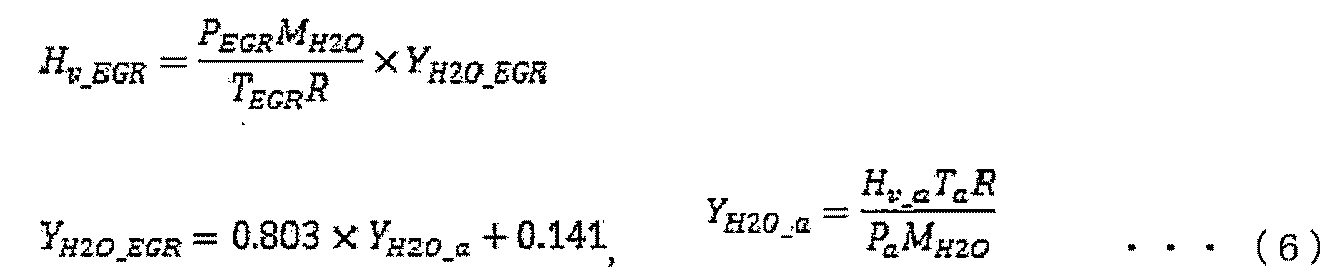
YH2O_EGR:EGR中の水のモル分率 [mol/mol]、
YH2O_a :大気中の水のモル分率 [mol/mol]
次に、ECU20Aは、ステップS1206において、インタークーラ温度センサ8Aの出力信号(インタークーラ温度)を読み込み、ステップS1207において、飽和水蒸気分圧演算部52Aにて、読み込んだインタークーラ温度センサ8Aの出力信号等から、上記した式(2)を用いて飽和水蒸気分圧P’H2Oを演算する。
次に、ECU20Aは、ステップS1208において、比較部53Aにて、ステップS1205で演算した吸気水蒸気分圧PH2OとステップS1207で演算した飽和水蒸気分圧P’H2Oとを上記した式(3)を用いて比較し、凝縮水が発生する条件であるか否かを判定する。
ECU20Aは、上記した式(3)が成立する場合には凝縮水が発生する条件であると判定してステップS1209に進む。一方、ECU20Aは、上記した式(3)が成立しない、すなわち吸気水蒸気分圧PH2Oが飽和水蒸気分圧P’H2O以下である場合には凝縮水が発生しない条件であると判定して一連の制御を終了する。
ECU20Aは、凝縮水が発生する条件であると判定すると、ステップS1209において、排気温度限界やノッキング限界等の観点からEGR率γEGRの低減可能性を判断するために、以下の式(7)を用いて現在のEGR率γEGRが運転限界であるEGR率γLIM以下であるか否かを判定する。ここで、運転限界であるEGR率γLIMは、例えば排気温度限界やノッキング限界等の観点から予め設定されており、運転条件毎にECU20Aに記憶されている。

ECU20Aは、上記した式(7)が成立する場合には、EGR率をこれ以上減少させることできないと判断してステップS1211に進む。一方、ECU20Aは、上記した式(7)が成立しない、すなわち現在のEGR率γEGRが運転限界であるEGR率γLIMよりも大きい場合にはステップS1210に進み、EGR率を低下させるべく、EGR弁41Aの開度を減少させて一連の制御を終了する。
ECU20Aは、凝縮水が発生する条件であり、かつ、EGR率をこれ以上減少させることできないと判定すると、上記した第1実施形態のステップS607~S610(図6参照)と同様、ステップS1211において、吸気圧力(過給圧力)を低下させるためにウェイストゲート弁11Aの開度を増加させて過給機4Aの駆動状態(例えば、回転数等)を制御する。次いで、ECU20Aは、ステップS1212において、過給圧力の低下に伴う出力低下を補うために、変速機30Aの変速比を増加させてエンジン回転数を上昇させる。
次に、ECU20Aは、ステップS1213において、現在の運転条件における点火時期がノッキング限界点(つまり、トレースノッキング点)に設定されているか否かを判定し、現在の運転条件における点火時期がノッキング限界点であると判定した場合には、一連の制御を終了する。一方、ECU20Aは、現在の運転条件における点火時期がノッキング限界点でない、すなわちエンジン100Aのノッキング発生までに余裕があると判定した場合には、ステップS1214において、インタークーラ温度を上昇させるために、インタークーラ7Aのインタークーラ冷却水弁7aAの開度を低下させ、インタークーラ7Aの冷却水路に流れる冷却水の流量を減少させる。なお、インタークーラ冷却水弁7aAの開度を低下させる代わりに、インタークーラ7Aの冷却水路にヒータ等を配設し、該ヒータを制御してインタークーラ7Aの冷却水路に流れる冷却水の温度を直接上昇させて、インタークーラ温度を上昇させてもよい。
図13は、図8に示す制御装置(ECU)による凝縮水発生判定及び凝縮水発生回避の制御内容を時系列で示したものである。図13では、上段から、凝縮水発生判定フラグ、大気湿度、インタークーラ下流の水蒸気分圧(吸気水蒸気分圧および飽和水蒸気分圧)、アクセル開度、EGR弁開度、EGR率、ウェイストゲート弁開度、吸気圧力、変速比(エンジン回転数)を時間列で示している。また、図13に示す例では、ドライバがアクセルペダルを二段階で踏み込んで車両が二段階で加速する場面を想定している。
図示するように、ドライバがアクセルを踏み込むに伴い、ウェイストゲート弁11Aの開度(ウェイストゲート弁開度)が減少され、吸気圧力(過給圧力)が上昇し、それに伴い、インタークーラ7A下流の吸気水蒸気分圧PH2Oが上昇する。
時刻t1になると、上昇した吸気水蒸気分圧PH2Oが飽和水蒸気分圧P’H2O、より具体的には飽和水蒸気分圧P’H2Oと制御裕度に関するパラメータαとの積算値を超過して凝縮水判定フラグが1となる。凝縮水判定フラグが1となる、すなわち凝縮水が発生する条件であると判定されると、凝縮水発生回避制御として、まず、EGR率γEGRを低下させるべく、EGR弁41Aの開度(EGR弁開度)を減少させる。ここで、EGR率γEGRは運転限界であるEGR率γLIMよりも大きい。アクセル開度の上昇に伴い、吸気圧力(過給圧力)は依然として上昇していくものの、EGR率γEGRの減少により吸気水蒸気分圧PH2Oが低下する。
時刻t2になると、ドライバによるアクセル踏み込み量が略一定となり、EGR率の減少により吸気水蒸気分圧PH2Oが飽和水蒸気分圧P’H2O、より具体的には飽和水蒸気分圧P’H2Oとパラメータαとの積算値を下回り、凝縮水判定フラグが再び0に戻る。そのため、それ以降では、アクセル開度が一定のもとで、EGR弁開度およびウェイストゲート弁開度を略一定に保持する。
時刻t3には、再びドライバのアクセル踏み込みによる加速操作が開始され、ウェイストゲート弁開度が減少され、上昇した吸気水蒸気分圧PH2Oが飽和水蒸気分圧P’H2O、より具体的には飽和水蒸気分圧P’H2Oと制御裕度に関するパラメータαとの積算値を超過して凝縮水判定フラグが再び1となる。凝縮水判定フラグが1となると、上記と同様、まず、EGR率γEGRを低下させるべく、EGR弁開度を減少させる。
時刻t4になり、減少したEGR率γEGRが運転限界であるEGR率γLIMに到達すると、これ以降は、ノッキング発生や空気量変動等による運転性低下の観点からEGR率γEGRを減少させることができない。そのため、EGR弁開度を略一定に保持した状態で、ウェイストゲート弁11Aを開いて吸気圧力(過給圧力)を減少させると共に、出力を維持するべく、変速機30Aの変速比を増加させてエンジン回転数を上昇させる。
時刻t5になると、吸気圧力(過給圧力)の減少により吸気水蒸気分圧PH2Oが飽和水蒸気分圧P’H2O、より具体的には飽和水蒸気分圧P’H2Oとパラメータαとの積算値を下回り、凝縮水判定フラグが再び0に戻るため、それ以降では、ウェイストゲート弁開度を略一定に保持する。
時刻t6になると、ドライバによるアクセル踏み込み量が略一定となるため、それ以降では、アクセル開度が一定のもとで、EGR弁開度、ウェイストゲート弁開度、および変速比を略一定に保持する。
なお、図13に示す例では、点火時期がノッキング限界点に設定されていると仮定して、インタークーラ温度の上昇制御を実施しない形態について説明したが、点火時期がノッキング限界点に設定されていない場合には、図7に基づき説明したように、インタークーラ冷却水弁開度を低下させたり、インタークーラの冷却水路に流れる冷却水の温度を直接上昇させて、インタークーラ温度を上昇させてもよい。
このように、第2実施形態の制御装置によれば、過給機30Aおよび低圧EGRシステムを備えたエンジン100Aにおいて、吸気管18Aに配設された湿度センサ3Aにより検出された吸気湿度に基づき凝縮水発生の有無を判定し、その判定結果に基づいて過給機30Aの駆動状態やEGR弁41Aの開度等を制御し、吸気圧力(過給圧力)を調整して凝縮水発生回避制御を実施することにより、凝縮水が発生しやすい低圧EGRシステムを備えたエンジン100Aにおいても、例えばインタークーラ内もしくはその下流での凝縮水発生をより効果的に回避することができ、エンジンへのダメージや吸気管の腐食、運転性の悪化を効果的に抑制することができる。
また、インタークーラ7A直後の吸気の水蒸気分圧とインタークーラ7A直後の吸気中の飽和水蒸気分圧とを比較して凝縮水発生の有無を判定し、凝縮水が発生すると判定された場合に、EGR弁41Aの開度を制御してEGR管40Aを流れるEGRガスの流量を減少させ、EGRガスの流量が下限値に到達した後に、過給機4Aの駆動状態を制御して吸気圧力を調整して凝縮水発生回避制御を実施することにより、凝縮水発生を迅速に抑制できると共に、EGRガスの流量減少に伴うノッキング発生や空気量変動等の運転性の悪化を抑制しつつ、凝縮水発生を効果的に抑制することができる。
なお、上記する第2実施形態では、EGR管40Aを流れるEGRガスが湿度センサ3Aの下流側且つ過給機4Aのコンプレッサ4aAの上流側に還流される、すなわち、湿度センサ3Aが、EGR管40Aと吸気管18Aとの接続点よりも上流側に配設され、湿度センサ3AによりEGRガスと混合される前の吸気の湿度を検出するため、上記した式(4)等で示すように、湿度センサ3Aと吸気圧力センサ14Aと差圧センサ43AとEGR温度センサ44Aの出力信号等から吸気中の水蒸気分圧PH2Oを演算した。一方で、EGRシステムを備えたエンジン100Aにおいて、EGR管40Aを流れるEGRガスが湿度センサ3Aの上流側に還流される、すなわち湿度センサ3Aが、EGR管40Aと吸気管18Aとの接続点よりも下流側に配設され、湿度センサ3AによりEGRガスと混合される後の吸気の湿度を検出する場合には、第1実施形態と同様、上記した式(1)を用いて、湿度センサ3Aと吸気圧力センサ14Aの出力信号等から吸気中の水蒸気分圧PH2Oを演算することができる。
また、上記する第1及び第2実施形態では、過給機のタービンの上流側と下流側をバイパスするバイパス流路に配設されたウェイストゲート弁の開度を制御することにより過給機の駆動状態(例えば、回転数)を制御する形態について説明したが、例えば過給機の段数を切替える等、ウェイストゲート弁の開度の制御以外の方法により過給機の駆動状態を制御してもよいことは勿論である。
なお、本発明は上記した第1及び第2実施形態に限定されるものではなく、様々な変形形態が含まれる。例えば、上記した第1及び第2実施形態は本発明を分かりやすく説明するために詳細に説明したものであり、必ずしも説明した全ての構成を備えるものに限定されるものではない。また、ある実施形態の構成の一部を他の実施形態の構成に置き換えることが可能であり、また、ある実施形態の構成に他の実施形態の構成を加えることも可能である。また、各実施形態の構成の一部について、他の構成の追加・削除・置換をすることが可能である。
また、制御線や情報線は説明上必要と考えられるものを示しており、製品上必ずしも全ての制御線や情報線を示しているとは限らない。実際には殆ど全ての構成が相互に接続されていると考えてもよい。
1…エアフローセンサ
2…電子制御スロットル
3…湿度センサ(湿度検出部)
3a…基板
3b…正電極
3c…負電極
3d…感湿膜
4…過給機
4a…コンプレッサ
4b…タービン
5…可変バルブ
6…吸気マニホールド
7…インタークーラ
7a…インタークーラ冷却水弁
8…インタークーラ温度センサ
9…空燃比センサ
10…三元触媒
11…ウェイストゲート弁
12…アクセル開度センサ
13…インジェクタ
14…吸気圧力センサ
15…シリンダ
16…排気管
17…点火プラグ
18…吸気管
19…バイパス流路
20…ECU(制御装置)
20a…入力回路
20b…入出力ポート
20c…RAM
20d…ROM
20e…CPU
20f…電子制御スロットル駆動回路
20g…インジェクタ駆動回路
20h…ウェイストゲート弁駆動回路
20j…インタークーラ冷却水弁駆動回路
20k…変速機駆動回路
20mA…EGR弁駆動回路
30…変速機
40A…EGR管
41A…EGR弁
42A…EGRクーラ
43A…差圧センサ(EGR流量検出部)
44A…EGR温度センサ(EGR温度検出部)
51…吸気水蒸気分圧演算部
52…飽和水蒸気分圧演算部
53…比較部
54…凝縮水発生判定部
55…凝縮水発生回避制御部
56…診断部
57…補正部
100…エンジン(内燃機関)
Claims (18)
- 燃焼室に導入される吸気の湿度を検出する湿度検出部と前記吸気を過給する過給機とを備えた内燃機関の制御装置であって、
前記制御装置は、前記吸気の湿度に基づき前記過給機の駆動状態を制御して前記吸気の圧力を調整することを特徴とする内燃機関の制御装置。 - 前記制御装置は、前記吸気の湿度が高くなると前記吸気の圧力を低下させるように前記過給機の駆動状態を制御することを特徴とする、請求項1に記載の内燃機関の制御装置。
- 前記制御装置は、前記過給機を構成するタービンの上流側と下流側をバイパスするバイパス流路に配設されたウェイストゲート弁の開度を制御することによって前記過給機の駆動状態を制御することを特徴とする、請求項1に記載の内燃機関の制御装置。
- 前記制御装置は、前記吸気を冷却するためのインタークーラ下流の吸気の水蒸気分圧と前記インタークーラ下流の吸気の飽和水蒸気分圧とに基づいて凝縮水発生の有無を判定する凝縮水発生判定部と、前記凝縮水発生判定部により凝縮水が発生すると判定された場合に、凝縮水発生を回避するべく前記過給機の駆動状態を制御して前記吸気の圧力を調整する凝縮水発生回避制御部と、を備えることを特徴とする、請求項1に記載の内燃機関の制御装置。
- 前記凝縮水発生回避制御部は、前記凝縮水発生判定部により凝縮水が発生すると判定された場合に、前記インタークーラ下流の吸気の温度を上昇させる、もしくは、前記内燃機関の動力軸に連結された変速機の変速比を増加させることを特徴とする、請求項4に記載の内燃機関の制御装置。
- 前記凝縮水発生回避制御部は、前記インタークーラの冷却水路に流れる冷却水の流量を減少させる、もしくは、前記冷却水の温度を上昇させることにより、前記インタークーラ下流の吸気の温度を上昇させることを特徴とする、請求項5に記載の内燃機関の制御装置。
- 前記凝縮水発生回避制御部は、前記内燃機関のノッキング発生までに余裕があると判定した場合に、前記インタークーラ下流の吸気の温度を上昇させることを特徴とする、請求項5に記載の内燃機関の制御装置。
- 前記凝縮水発生判定部は、前記吸気の湿度と前記過給機を構成するコンプレッサの下流の吸気の圧力とに基づいて前記水蒸気分圧を演算する、又は、前記インタークーラ下流の吸気の温度に基づいて前記飽和水蒸気分圧を演算することを特徴とする、請求項4に記載の内燃機関の制御装置。
- 前記内燃機関には、前記過給機のタービンの下流側の排気管と前記過給機のコンプレッサの上流側の吸気管とを連結するEGR管と、前記EGR管を流れるEGRガスの流量を制御するためのEGR弁とが備えられ、
前記凝縮水発生回避制御部は、前記凝縮水発生判定部により凝縮水が発生すると判定された場合に、前記EGR弁の開度を制御して前記EGRガスの流量を減少させることを特徴とする、請求項4に記載の内燃機関の制御装置。 - 前記凝縮水発生回避制御部は、前記凝縮水発生判定部により凝縮水が発生すると判定された場合に、前記EGR弁の開度を制御して前記EGRガスの流量を所定値まで減少させた後に、前記過給機の駆動状態を制御して前記吸気の圧力を調整することを特徴とする、請求項9に記載の内燃機関の制御装置。
- 前記所定値は、ノッキング限界もしくは排気温度限界によって規定されることを特徴とする、請求項10に記載の内燃機関の制御装置。
- 前記内燃機関には、前記過給機のタービンの下流側の排気管と前記過給機のコンプレッサの上流側の吸気管とを連結するEGR管と、前記EGR管を流れるEGRガスの流量を制御するためのEGR弁と、前記EGRガスの流量を検出するEGR流量検出部と、前記EGRガスの温度を検出するEGR温度検出部と、が備えられ、
前記凝縮水発生判定部は、
前記湿度検出部が、前記EGR管と前記吸気管との接続点よりも上流側に配設されている場合には、前記吸気の湿度と前記過給機を構成するコンプレッサの下流の吸気の圧力と前記EGRガスの流量と前記EGRガスの温度とに基づいて前記水蒸気分圧を演算し、
前記湿度検出部が、前記EGR管と前記吸気管との接続点よりも下流側に配設されている場合には、前記吸気の湿度と前記過給機を構成するコンプレッサの下流の吸気の圧力とに基づいて前記水蒸気分圧を演算することを特徴とする、請求項4に記載の内燃機関の制御装置。 - 前記制御装置は、前記湿度検出部の異常もしくは故障を診断する診断部を更に備え、
前記凝縮水発生判定部は、前記診断部により前記湿度検出部が異常もしくは故障であると判定された場合、前記吸気の湿度が湿度上限値であるとして凝縮水発生の有無を判定することを特徴とする、請求項4に記載の内燃機関の制御装置。 - 前記制御装置は、前記内燃機関が搭載された車両の外界環境に関する情報、及び/又は、ドライバによる前記車両の操作に関する情報に基づいて前記湿度検出部により検出された前記吸気の湿度を補正することを特徴とする、請求項1に記載の内燃機関の制御装置。
- 前記車両の外界環境に関する情報は、車両の外界環境を認識するカメラ又はレインセンサから取得されることを特徴とする、請求項14に記載の内燃機関の制御装置。
- 前記車両の操作は、前記車両に装備されたワイパー又はフォグランプの操作を含むことを特徴とする、請求項14に記載の内燃機関の制御装置。
- 前記制御装置は、前記内燃機関の燃焼室に導入される吸気の流量及び燃料の流量と排気の空燃比とに基づいて前記湿度検出部により検出された前記吸気の湿度を補正することを特徴とする、請求項1に記載の内燃機関の制御装置。
- 前記内燃機関には、前記過給機のタービンの下流側の排気管と前記過給機のコンプレッサの上流側の吸気管とを連結するEGR管と、前記EGR管を流れるEGRガスの流量を制御するためのEGR弁と、が備えられ、
前記制御装置は、前記EGR管に流れるEGRガスの流量が所定値以下である場合に、前記湿度検出部により検出された前記吸気の湿度を補正することを特徴とする、請求項1に記載の内燃機関の制御装置。
Applications Claiming Priority (2)
| Application Number | Priority Date | Filing Date | Title |
|---|---|---|---|
| JP2013215757A JP6141746B2 (ja) | 2013-10-16 | 2013-10-16 | 内燃機関の制御装置 |
| JP2013-215757 | 2013-10-16 |
Publications (1)
| Publication Number | Publication Date |
|---|---|
| WO2015056579A1 true WO2015056579A1 (ja) | 2015-04-23 |
Family
ID=52828027
Family Applications (1)
| Application Number | Title | Priority Date | Filing Date |
|---|---|---|---|
| PCT/JP2014/076488 Ceased WO2015056579A1 (ja) | 2013-10-16 | 2014-10-03 | 内燃機関の制御装置 |
Country Status (2)
| Country | Link |
|---|---|
| JP (1) | JP6141746B2 (ja) |
| WO (1) | WO2015056579A1 (ja) |
Cited By (6)
| Publication number | Priority date | Publication date | Assignee | Title |
|---|---|---|---|---|
| US20150361869A1 (en) * | 2013-01-29 | 2015-12-17 | Mitsubishi Heavy Industries, Ltd. | Multi-stage supercharging system and device and method for controlling the same |
| WO2017033647A1 (ja) * | 2015-08-25 | 2017-03-02 | 日立オートモティブシステムズ株式会社 | 制御装置 |
| JP2017227210A (ja) * | 2016-06-15 | 2017-12-28 | 日産自動車株式会社 | 内燃機関の制御方法及び内燃機関の制御装置 |
| CN108930587A (zh) * | 2017-05-19 | 2018-12-04 | 广州汽车集团股份有限公司 | 一种增压发动机系统及其控制方法 |
| JP2020002799A (ja) * | 2018-06-25 | 2020-01-09 | 株式会社豊田自動織機 | 内燃機関の制御システム |
| CN114810332A (zh) * | 2022-03-30 | 2022-07-29 | 江铃汽车股份有限公司 | 中冷系统调控方法、系统、终端设备及存储介质 |
Families Citing this family (11)
| Publication number | Priority date | Publication date | Assignee | Title |
|---|---|---|---|---|
| KR101664081B1 (ko) * | 2015-06-29 | 2016-10-24 | 현대자동차 주식회사 | 수냉식 인터쿨러를 갖는 엔진시스템 |
| JP2017020406A (ja) * | 2015-07-10 | 2017-01-26 | 日立オートモティブシステムズ株式会社 | 内燃機関用制御装置 |
| JP6659267B2 (ja) * | 2015-08-10 | 2020-03-04 | 日立オートモティブシステムズ株式会社 | 内燃機関の制御装置 |
| JP6058102B1 (ja) * | 2015-10-07 | 2017-01-11 | 三菱電機株式会社 | 内燃機関の制御装置および内燃機関の制御方法 |
| CN108699980B (zh) * | 2016-01-27 | 2021-06-18 | 日立汽车系统株式会社 | 内燃机控制装置 |
| DE112017000237T5 (de) | 2016-01-27 | 2018-10-04 | Hitachi Automotive Systems, Ltd. | Steuergerät |
| JP6315008B2 (ja) | 2016-03-02 | 2018-04-25 | トヨタ自動車株式会社 | 内燃機関の制御システム |
| JP6766620B2 (ja) | 2016-12-02 | 2020-10-14 | 株式会社デンソー | 物理量計測装置、異常検出装置、及び異常検出方法 |
| JP6874875B2 (ja) * | 2020-03-06 | 2021-05-19 | 株式会社デンソー | 物理量計測装置、及びセンサアッセンブリ |
| JP7054716B2 (ja) | 2020-03-18 | 2022-04-14 | 本田技研工業株式会社 | 内燃機関の過給圧制御装置 |
| WO2026069448A1 (ja) * | 2024-09-25 | 2026-04-02 | 日産自動車株式会社 | 車両の制御方法及び車両の制御装置 |
Citations (11)
| Publication number | Priority date | Publication date | Assignee | Title |
|---|---|---|---|---|
| JPS5823243A (ja) * | 1981-08-03 | 1983-02-10 | Mazda Motor Corp | エンジンの吸気装置 |
| JPS5874846A (ja) * | 1981-10-28 | 1983-05-06 | Mitsubishi Motors Corp | 内燃機関の駆動制御方法 |
| JPS61152925A (ja) * | 1984-12-26 | 1986-07-11 | Daihatsu Motor Co Ltd | 車輌用エンジンの過給圧制御方法 |
| JPH0274857A (ja) * | 1988-07-22 | 1990-03-14 | Ford Motor Co | 酸素ポンプ作用を有するデバイス及び排ガス再循環量の測定方法 |
| JPH10239261A (ja) * | 1997-02-28 | 1998-09-11 | Yamatake Honeywell Co Ltd | 湿度センサの故障検出装置 |
| JP2006144671A (ja) * | 2004-11-19 | 2006-06-08 | Mitsubishi Heavy Ind Ltd | ウェストゲートバルブを備えた排気ターボ過給機付きエンジン及びその運転方法 |
| JP2010223179A (ja) * | 2009-03-25 | 2010-10-07 | Toyota Industries Corp | 低圧egr装置を備えた内燃機関 |
| JP2012219694A (ja) * | 2011-04-07 | 2012-11-12 | Honda Motor Co Ltd | 内燃機関の停止制御装置 |
| JP2013036452A (ja) * | 2011-08-11 | 2013-02-21 | Mitsubishi Motors Corp | 内燃機関 |
| JP2013194691A (ja) * | 2012-03-22 | 2013-09-30 | Toyota Motor Corp | 内燃機関の筒内水分検出装置、内燃機関の制御装置 |
| JP2013204447A (ja) * | 2012-03-27 | 2013-10-07 | Toyota Motor Corp | 内燃機関の制御装置 |
Family Cites Families (3)
| Publication number | Priority date | Publication date | Assignee | Title |
|---|---|---|---|---|
| JPS63159637A (ja) * | 1986-12-24 | 1988-07-02 | Toyota Motor Corp | 内燃機関の空燃比制御装置 |
| JPH08158909A (ja) * | 1994-12-02 | 1996-06-18 | Nissan Motor Co Ltd | 内燃機関の空燃比制御装置 |
| JP5708505B2 (ja) * | 2012-01-13 | 2015-04-30 | トヨタ自動車株式会社 | 冷却システムの制御装置 |
-
2013
- 2013-10-16 JP JP2013215757A patent/JP6141746B2/ja active Active
-
2014
- 2014-10-03 WO PCT/JP2014/076488 patent/WO2015056579A1/ja not_active Ceased
Patent Citations (11)
| Publication number | Priority date | Publication date | Assignee | Title |
|---|---|---|---|---|
| JPS5823243A (ja) * | 1981-08-03 | 1983-02-10 | Mazda Motor Corp | エンジンの吸気装置 |
| JPS5874846A (ja) * | 1981-10-28 | 1983-05-06 | Mitsubishi Motors Corp | 内燃機関の駆動制御方法 |
| JPS61152925A (ja) * | 1984-12-26 | 1986-07-11 | Daihatsu Motor Co Ltd | 車輌用エンジンの過給圧制御方法 |
| JPH0274857A (ja) * | 1988-07-22 | 1990-03-14 | Ford Motor Co | 酸素ポンプ作用を有するデバイス及び排ガス再循環量の測定方法 |
| JPH10239261A (ja) * | 1997-02-28 | 1998-09-11 | Yamatake Honeywell Co Ltd | 湿度センサの故障検出装置 |
| JP2006144671A (ja) * | 2004-11-19 | 2006-06-08 | Mitsubishi Heavy Ind Ltd | ウェストゲートバルブを備えた排気ターボ過給機付きエンジン及びその運転方法 |
| JP2010223179A (ja) * | 2009-03-25 | 2010-10-07 | Toyota Industries Corp | 低圧egr装置を備えた内燃機関 |
| JP2012219694A (ja) * | 2011-04-07 | 2012-11-12 | Honda Motor Co Ltd | 内燃機関の停止制御装置 |
| JP2013036452A (ja) * | 2011-08-11 | 2013-02-21 | Mitsubishi Motors Corp | 内燃機関 |
| JP2013194691A (ja) * | 2012-03-22 | 2013-09-30 | Toyota Motor Corp | 内燃機関の筒内水分検出装置、内燃機関の制御装置 |
| JP2013204447A (ja) * | 2012-03-27 | 2013-10-07 | Toyota Motor Corp | 内燃機関の制御装置 |
Cited By (14)
| Publication number | Priority date | Publication date | Assignee | Title |
|---|---|---|---|---|
| US20150361869A1 (en) * | 2013-01-29 | 2015-12-17 | Mitsubishi Heavy Industries, Ltd. | Multi-stage supercharging system and device and method for controlling the same |
| US10557405B2 (en) * | 2013-01-29 | 2020-02-11 | Mitsubishi Heavy Industries, Ltd. | Multi-stage supercharging system and device and method for controlling the same |
| CN107923344A (zh) * | 2015-08-25 | 2018-04-17 | 日立汽车系统株式会社 | 控制装置 |
| JPWO2017033647A1 (ja) * | 2015-08-25 | 2018-07-19 | 日立オートモティブシステムズ株式会社 | 制御装置 |
| US20180252186A1 (en) * | 2015-08-25 | 2018-09-06 | Hitachi Automotive Systems, Ltd. | Control Device |
| EP3343011A4 (en) * | 2015-08-25 | 2019-04-17 | Hitachi Automotive Systems, Ltd. | CONTROL DEVICE |
| WO2017033647A1 (ja) * | 2015-08-25 | 2017-03-02 | 日立オートモティブシステムズ株式会社 | 制御装置 |
| CN107923344B (zh) * | 2015-08-25 | 2020-04-24 | 日立汽车系统株式会社 | 控制装置 |
| JP2017227210A (ja) * | 2016-06-15 | 2017-12-28 | 日産自動車株式会社 | 内燃機関の制御方法及び内燃機関の制御装置 |
| CN108930587A (zh) * | 2017-05-19 | 2018-12-04 | 广州汽车集团股份有限公司 | 一种增压发动机系统及其控制方法 |
| CN108930587B (zh) * | 2017-05-19 | 2024-07-26 | 广州汽车集团股份有限公司 | 一种增压发动机系统及其控制方法 |
| JP2020002799A (ja) * | 2018-06-25 | 2020-01-09 | 株式会社豊田自動織機 | 内燃機関の制御システム |
| JP7005437B2 (ja) | 2018-06-25 | 2022-01-21 | 株式会社豊田自動織機 | 内燃機関の制御システム |
| CN114810332A (zh) * | 2022-03-30 | 2022-07-29 | 江铃汽车股份有限公司 | 中冷系统调控方法、系统、终端设备及存储介质 |
Also Published As
| Publication number | Publication date |
|---|---|
| JP2015078637A (ja) | 2015-04-23 |
| JP6141746B2 (ja) | 2017-06-07 |
Similar Documents
| Publication | Publication Date | Title |
|---|---|---|
| JP6141746B2 (ja) | 内燃機関の制御装置 | |
| JP4124143B2 (ja) | 電動機付過給機の制御装置 | |
| JP6208097B2 (ja) | 内燃機関の装置 | |
| CN108626038B (zh) | 内燃机的控制装置 | |
| JP4861915B2 (ja) | 内燃機関の制御装置 | |
| US9957877B2 (en) | Control apparatus for internal combustion engine | |
| JP6860313B2 (ja) | エンジンの制御方法、及び、エンジン | |
| JP5331613B2 (ja) | 内燃機関の筒内ガス量推定装置 | |
| JP4833924B2 (ja) | 内燃機関の制御装置 | |
| CN100404830C (zh) | 内燃机 | |
| JP2010168958A (ja) | 内燃機関のegr制御装置 | |
| US11333089B2 (en) | Supercharging pressure control device for internal combustion engine | |
| JP4818344B2 (ja) | 内燃機関の過給圧制御装置 | |
| JP2016151254A (ja) | 過給機付き内燃機関の制御装置 | |
| US20180252186A1 (en) | Control Device | |
| JP6127906B2 (ja) | 内燃機関の制御装置 | |
| JP5111534B2 (ja) | 内燃機関のegr制御装置 | |
| US8229654B2 (en) | Device for limiting output of internal combustion engine when the engine has abnormality | |
| JP5171740B2 (ja) | 内燃機関の制御装置 | |
| JP2010127219A (ja) | ディーゼルエンジンの燃料制御装置 | |
| JP2007303294A (ja) | 過給機付き内燃機関の制御装置 | |
| JP5598376B2 (ja) | 内燃機関装置 | |
| JP2007255194A (ja) | 内燃機関の制御装置 | |
| JP2016173061A (ja) | 内燃機関のエンジントルク補正装置 | |
| KR20070092520A (ko) | 디젤 엔진의 연료분사시기 제어방법 및 시스템 |
Legal Events
| Date | Code | Title | Description |
|---|---|---|---|
| 121 | Ep: the epo has been informed by wipo that ep was designated in this application |
Ref document number: 14854045 Country of ref document: EP Kind code of ref document: A1 |
|
| NENP | Non-entry into the national phase |
Ref country code: DE |
|
| 122 | Ep: pct application non-entry in european phase |
Ref document number: 14854045 Country of ref document: EP Kind code of ref document: A1 |