WO2015056431A1 - Particle fractionation apparatus, particle fractionation method and particle fractionation program - Google Patents
Particle fractionation apparatus, particle fractionation method and particle fractionation program Download PDFInfo
- Publication number
- WO2015056431A1 WO2015056431A1 PCT/JP2014/005167 JP2014005167W WO2015056431A1 WO 2015056431 A1 WO2015056431 A1 WO 2015056431A1 JP 2014005167 W JP2014005167 W JP 2014005167W WO 2015056431 A1 WO2015056431 A1 WO 2015056431A1
- Authority
- WO
- WIPO (PCT)
- Prior art keywords
- particle
- droplets
- fractionating apparatus
- particles
- mode
- Prior art date
- Legal status (The legal status is an assumption and is not a legal conclusion. Google has not performed a legal analysis and makes no representation as to the accuracy of the status listed.)
- Ceased
Links
Images
Classifications
-
- G—PHYSICS
- G01—MEASURING; TESTING
- G01N—INVESTIGATING OR ANALYSING MATERIALS BY DETERMINING THEIR CHEMICAL OR PHYSICAL PROPERTIES
- G01N15/00—Investigating characteristics of particles; Investigating permeability, pore-volume or surface-area of porous materials
- G01N15/10—Investigating individual particles
- G01N15/14—Optical investigation techniques, e.g. flow cytometry
- G01N15/1425—Optical investigation techniques, e.g. flow cytometry using an analyser being characterised by its control arrangement
-
- G—PHYSICS
- G01—MEASURING; TESTING
- G01N—INVESTIGATING OR ANALYSING MATERIALS BY DETERMINING THEIR CHEMICAL OR PHYSICAL PROPERTIES
- G01N15/00—Investigating characteristics of particles; Investigating permeability, pore-volume or surface-area of porous materials
- G01N15/10—Investigating individual particles
- G01N15/14—Optical investigation techniques, e.g. flow cytometry
-
- B—PERFORMING OPERATIONS; TRANSPORTING
- B03—SEPARATION OF SOLID MATERIALS USING LIQUIDS OR USING PNEUMATIC TABLES OR JIGS; MAGNETIC OR ELECTROSTATIC SEPARATION OF SOLID MATERIALS FROM SOLID MATERIALS OR FLUIDS; SEPARATION BY HIGH-VOLTAGE ELECTRIC FIELDS
- B03C—MAGNETIC OR ELECTROSTATIC SEPARATION OF SOLID MATERIALS FROM SOLID MATERIALS OR FLUIDS; SEPARATION BY HIGH-VOLTAGE ELECTRIC FIELDS
- B03C7/00—Separating solids from solids by electrostatic effect
- B03C7/003—Pretreatment of the solids prior to electrostatic separation
-
- B—PERFORMING OPERATIONS; TRANSPORTING
- B07—SEPARATING SOLIDS FROM SOLIDS; SORTING
- B07C—POSTAL SORTING; SORTING INDIVIDUAL ARTICLES, OR BULK MATERIAL FIT TO BE SORTED PIECE-MEAL, e.g. BY PICKING
- B07C5/00—Sorting according to a characteristic or feature of the articles or material being sorted, e.g. by control effected by devices which detect or measure such characteristic or feature; Sorting by manually actuated devices, e.g. switches
- B07C5/34—Sorting according to other particular properties
- B07C5/342—Sorting according to other particular properties according to optical properties, e.g. colour
-
- G—PHYSICS
- G01—MEASURING; TESTING
- G01N—INVESTIGATING OR ANALYSING MATERIALS BY DETERMINING THEIR CHEMICAL OR PHYSICAL PROPERTIES
- G01N15/00—Investigating characteristics of particles; Investigating permeability, pore-volume or surface-area of porous materials
- G01N15/01—Investigating characteristics of particles; Investigating permeability, pore-volume or surface-area of porous materials specially adapted for biological cells, e.g. blood cells
-
- G—PHYSICS
- G01—MEASURING; TESTING
- G01N—INVESTIGATING OR ANALYSING MATERIALS BY DETERMINING THEIR CHEMICAL OR PHYSICAL PROPERTIES
- G01N15/00—Investigating characteristics of particles; Investigating permeability, pore-volume or surface-area of porous materials
- G01N15/10—Investigating individual particles
- G01N15/14—Optical investigation techniques, e.g. flow cytometry
- G01N15/149—Optical investigation techniques, e.g. flow cytometry specially adapted for sorting particles, e.g. by their size or optical properties
-
- G—PHYSICS
- G01—MEASURING; TESTING
- G01N—INVESTIGATING OR ANALYSING MATERIALS BY DETERMINING THEIR CHEMICAL OR PHYSICAL PROPERTIES
- G01N15/00—Investigating characteristics of particles; Investigating permeability, pore-volume or surface-area of porous materials
- G01N15/10—Investigating individual particles
- G01N2015/1028—Sorting particles
Definitions
- the present disclosure relates to a particle fractionation apparatus, a particle fractionation method, and a particle fractionation program, and more particularly, relates to a technology that sorts and collects particles based on an analysis result according to an optical technique.
- an optical measuring method using a flow cytometery is used in analyzing a biological microparticle, such as a cell, a microorganism, or a liposome.
- the flow cytometer is an analyzing apparatus that irradiates the microparticle, which flows through the inside of a flow path formed of a flow cell or a microchip, with light, and detects fluorescence or scattered light generated from each microparticle.
- the flow cytometer includes a function which sorts and collects only the microparticles having specific characteristics, based on an analysis result.
- a microparticle apparatus which considers a cell as a fractionation target is referred to as a 'cell sorter.
- the cell sorter makes liquid discharged from the flow path into liquid droplets by applying oscillation to the flow cell or the microchip by an oscillation element or the like (refer to Japanese Unexamined Patent Application Publication No. 2007-532874 and Japanese Unexamined Patent Application Publication No. 2010-190680, which are incorporated herein by reference).
- a progress direction of the liquid droplets separated from the flow path is changed by a deflecting plate or the like, and the liquid droplets are collected by a predetermined container or the like.
- a technology is suggested which distributes certain cells one by one to each reaction part of a base material used in a polymerase chain reaction (PCR) method or the like, by using a fractionation function by the cell sorter (refer to Japanese Unexamined Patent Application Publication No. 2010-510782, which is incorporated herein by reference).
- a particle fractionation apparatus includes a charging portion which imparts an electric charge to at least one part of liquid droplets ejected from an orifice that generates a fluid stream, and a first electric charge control portion which controls the charging portion to impart the electric charge to particle non-containing liquid droplets.
- the first electric charge control portion can determine whether or not particles are included in the liquid droplets.
- the scattered light is, for example, forward scattered light.
- the first electric charge control portion can control the charging portion to impart the electric charge to the liquid droplets.
- the first electric charge control portion may control the charging portion to impart the electric charge to the liquid droplets.
- the particle fractionation apparatus may include a second electric charge control portion which controls the charging portion to impart the electric charge to particle containing liquid droplets.
- a second electric charge control portion which controls the charging portion to impart the electric charge to particle containing liquid droplets.
- a particle fractionation method includes imparting an electric charge selectively to particle non-containing liquid droplets among liquid droplets ejected from an orifice which generates a fluid stream.
- the particle fractionation method according to the disclosure may further include imparting the electric charge selectively to the particle containing liquid droplets among the liquid droplets ejected from the orifice which generates the fluid stream.
- imparting the electric charge to the particle containing liquid droplets may be performed after imparting the electric charge to the particle non-containing liquid droplets.
- a program according to the disclosure causes an electric charge control portion of a particle fractionation apparatus to execute a function that imparts the electric charge selectively to the particle non-containing liquid droplets among the liquid droplets ejected from the orifice which generates the fluid stream.
- a particle fractionating apparatus may comprise a charging portion configured to apply voltages to an electrode that is arranged to contact liquid in a flow path for the liquid, a particle detection system configured to detect when no particle will be contained in a droplet produced from the liquid, and a charge controller connected to the charging portion and configured in a first mode to cause the charging portion to apply charge to the liquid so that the droplet that does not contain a particle will be charged.
- a particle fractionating apparatus may further comprise deflecting plates configured to support an electric field between the deflecting plates, such that charged droplets that do not contain particles will be deflected by the deflecting plates.
- a particle fractionating apparatus may further comprise deflecting plates configured to support an electric field between the deflecting plates, and wherein the charge controller is further operable in a second mode to cause the charging portion to apply charges to droplets produced from the flow path that contain particles such that the charged droplets that contain particles will be deflected by the deflecting plates.
- a particle fractionating apparatus may further comprise a microchip that includes the flow path and an orifice arranged at an end of the flow path and configured to emit droplets toward the deflecting plates.
- a particle fractionating apparatus may be configured to be manually switched between the first mode and the second mode.
- the particle detection system comprises a light detector arranged to detect light scattered from the flow path, wherein a signal from the light detector less than a predetermined threshold value indicates the absence of particles.
- the charge controller is configured in the first mode of operation to apply the voltages to the electrode responsive to at least receiving the signal from the particle detection system within a predetermined time interval.
- a method for fractionating particles may comprise acts of determining, by a particle detection system , the absence of particles in droplets produced by the particle fractionating apparatus, and causing, by a charge controller in a first mode of operation, the application of voltages to an electrode arranged to charge the droplets produced by the particle fractionating apparatus that do not contain particles such that the charged droplets that do not contain particles will be charged.
- a method may further comprise causing, by the charge controller in a second mode of operation, the application of voltages to the electrode such that droplets that contain particles will be charged.
- a method may further comprise receiving, by the charge controller, a signal from a particle detection system that indicates the presence or absence of a particle in a droplet produced by the particle fractionating apparatus.
- a method may further comprise providing the signal from a scattered light detector that is arranged to detect scattered light from a flow path that is used to form the droplet.
- methods of fractionating particles may be implemented as a storage device containing machine-readable instructions that, when executed by a particle fractionating apparatus, cause the particle fractionating apparatus to determine, by a particle detection system , the absence of particles in droplets produced by the particle fractionating apparatus, and cause, by the charge controller in a first mode of operation, the application of charges to the droplets produced by the particle fractionating apparatus that do not contain particles such that the charged droplets that do not contain particles will be charged.
- the storage device may further comprise machine-readable instructions that cause the particle fractionating apparatus to cause, by the charge controller in a second mode of operation, the application of charges to droplets produced by the particle fractionating apparatus that contain particles such that the charged droplets that contain particles will be deflected by deflecting plates.
- instructions for determining the presence or absence of particles in droplets depend upon receiving a signal within a predetermined time interval from a particle detection system, wherein the signal indicates the presence or absence of a particle in a flow path from which the droplets are produced.
- a particle fractionating apparatus comprises a scattered light detection system configured to detect when no particle will be contained in a droplet produced from a liquid in a flow path based upon comparing a detected signal with a threshold value, a charging portion configured to apply voltages to an electrode that is arranged to contact the liquid in the flow path, and a charge controller connected to the charging portion and operable in a first mode to cause the charging portion to apply a plurality of different voltages to the electrode responsive to receiving detected signals from the scattered light detection system that indicate no particles will be contained in droplets produced from the liquid.
- the particle fractionating apparatus may further comprise deflecting plates, wherein the applied plurality of different voltages are selected to charge the droplets so that they will be deflected to a plurality of predetermined locations by the deflecting plates.
- the particle fractionating apparatus may further comprise an orifice arranged at an end of the flow path, wherein the orifice and flow path are disposed on a microfluidic chip.
- the particle fractionating apparatus is configured to be manually switched between the first mode and a second mode of operation.
- the charge controller is configured to cause the charging portion to apply the plurality of different voltages only when the detected signals are received within predetermined time intervals.
- the scattered light detection system comprises a detector arranged to detect forward scattered light, sideward scattered light, Rayleigh scattered light, or Mie scattered light.
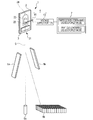
- FIG. 1 is a schematic view showing a configuration example of a particle fractionation apparatus according to an embodiment of the disclosure.
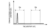
- FIG. 2 is a view showing a technique for determining 'particle containing' or 'particle non-containing' when a horizontal axis represents time and a vertical axis represents forward scattered light intensity.
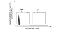
- FIG. 3 is a view showing a technique for determining 'particle containing' or 'particle non-containing' when a horizontal axis represents time and a vertical axis represents forward scattered light intensity.
- FIG. 1 is a schematic view showing a configuration example of a particle fractionation apparatus according to an embodiment of the disclosure.
- a particle fractionation apparatus 1 sorts and collects particles based on an analysis result by an optical technique or the like.
- the particle fractionation apparatus 1 includes a microchip 2, an oscillation element 3, a charging portion 4, an electric charge control portion 7, and deflecting plates 5a and 5b.
- Particles Particles which are analyzed and fractionated by the particle fractionation apparatus 1 of the embodiment include biological microparticles such as a cell, a microorganism, or a liposome, or synthetic particles such as latex particles, gel particles, or industrial particles.
- the biological microparticles include a chromosome, a liposome, a mitochondria, or an organelle which compose various cells.
- the cell includes a plant cell, an animal cell, or a blood cell.
- the microorganism includes a bacteria such as a coliform bacillus, a virus such as a tobacco mosaic virus, or a fungus such as a yeast fungus.
- the biological microparticles can even include a biological polymer, such as a nucleic acid, a protein, or a complex thereof.
- examples of the industrial particles can include particles formed by an organic polymeric material, an inorganic material, or a metal material.
- the organic polymeric material it is possible to use polystyrene, styrene-divinyl benzene, or polymethyl methacrylate.
- the inorganic material it is possible to use glass, silica, or a magnetic material.
- the metal material it is possible to use a gold colloid or aluminum.
- shapes of these particles are generally spherical, but may be non-spherical.
- a size or a weight is also not particularly limited.
- Microchip In the microchip 2, a sample inlet 22 to which the liquid (sample liquid) including particles as a fractionation target is introduced, a sheath inlet 23 to which the sheath liquid is introduced, and an absorption outlet 24 for eliminating a blockage or air bubbles, are formed.
- the sample liquid is introduced into the sample inlet 22, is merged with the sheath liquid introduced into the sheath inlet 23, sends the liquid to a sample flow path, and ejects the liquid from an orifice 21 provided at an end edge of the sample flow path.
- an absorption flow path which communicates with the absorption outlet 24 is connected to the sample flow path.
- the absorption flow path temporarily backflows a flow by making the inside of the sample flow path have a negative pressure and eliminates the blockage or the air bubbles.
- a negative pressure source such as a vacuum pump, is connected to the absorption outlet 24.
- the microchip 2 can be formed by glass or various types of plastics (PP, PC, COP, PDMS, or the like). It is preferable that material of the microchip 2 be a material which has few optical errors since the material has transmissivity with respect to measurement light irradiated from a light detection portion which will be described later, has low intrinsic fluorescence, and has low wavelength dispersion.
- Molding the microchip 2 can be performed by wet etching or dry etching of a glass-made substrate, by nanoimprint or injection molding of a plastic-made substrate, and by machining.
- the microchip 2 can be formed by sealing a substrate which molds the sample flow path or the like onto a substrate which is made of the same or different material.
- the oscillation element 3 is disposed to abut against a part of the microchip 2 or is provided as an internal configuration of the microchip 2.
- the oscillation element 3 imparts minute oscillation to the sheath liquid by oscillating the microchip 2 at a predetermined frequency, makes the liquid (the sample liquid and the sheath liquid) ejected from the orifice 21 into the liquid droplets, and generates a fluid stream (flow of the liquid droplets) S.
- the oscillation element 3 it is possible to use a piezoelectric element or the like.
- the charging portion 4 imparts the positive or negative electric charge to the liquid droplets ejected from the orifice 21, and is configured to have a voltage source (voltage supply portion 42) which applies a predetermined voltage to an electric charge electrode 41 and the electrode 41.
- the electric charge electrode 41 is disposed to be in contact with the sheath liquid and/or the sample liquid which flows through the flow path, and imparts the electric charge to the sheath liquid and/or the sample liquid, and is inserted into an electric charge electrode inlet of the microchip 2, for example.
- the electric charge electrode 41 is disposed to be in contact with the sample liquid, but the disclosure is not limited thereto.
- the electric charge electrode 41 may be disposed to be in contact with the sheath liquid, and may be in contact with both of the sample liquid and the sheath liquid. However, considering an influence on the cell of the fractionation target, it is preferable that the electric charge electrode 41 be disposed to be in contact with the sheath liquid.
- the deflecting plates 5a and 5b change a progress direction of each liquid droplet in the fluid stream S, induce predetermined collecting containers 6a and 6b, and are disposed to interpose the fluid stream S and to face each other.
- the electrode which is generally used.
- the electrical force (Coulomb force) is generated, and each liquid droplet is gravitated to any one of directions of the deflecting plates 5a and 5b.
- the particle fractionation apparatus 1 by changing the positive and negative electric charge and an amount of the electric charge to the liquid droplets, it is possible to control a direction of the flow (side stream) of the liquid droplets gravitated by the electric field. For this reason, it is possible to simultaneously fractionate a plurality of particles which are different from each other. In addition, it is possible to perform the fractionation of the particle containing liquid droplets and the fractionation of the particle non-containing liquid droplets simultaneously or sequentially.
- the collecting containers 6a and 6b collect the liquid droplets which flow between the deflecting plates 5a and 5b, and can use a base material in which a general-purpose plastic-made tube, a glass tube, or a plurality of reaction parts (well) are formed for an experiment. It is preferable that the collecting containers 6a and 6b be disposed to be exchangeable in the apparatus.
- the collecting container 6a when the collecting container 6a in a tube shape and the collecting container 6b (substrate) provided with a plurality of collecting parts (reaction parts) are used, the collecting container 6a receives non-objective particles, and it is possible to distribute certain particles one by one to each collecting part of the collecting container 6b.
- a liquid discharge path of the collected liquid may be connected to the collecting container 6a.
- each liquid droplet may be induced to any one of the collecting containers according to a presence or absence, and a size of an electrical working force between the deflecting plates 5a and 5b, and be collected.
- the electric charge control portion 7 controls imparting the electric charge to the liquid droplets, and is provided with a first electric charge control portion which carries out 'particle non-containing liquid droplets mode' that controls the charging portion to impart the predetermined electric charge to the particle non-containing liquid droplets.
- a method for determining 'particle containing' and 'particle non-containing' with respect to each liquid droplet is not particularly limited, but it is possible to determine based on a detection result of the scattered light measured by the light detection portion which will be described later.
- the electric charge control portion 7 determines 'particle non-containing' when intensity of the scattered light is equal to or less than a threshold value set in advance, controls the voltage supply portion 42 to impart the electric charge to the liquid droplets, and applies the voltage to the electric charge electrode 41. At that time, in a certain area and/or at a certain time, it is preferable that the first electric charge control portion determine a case where the scattered light is not detected or a case where the intensity of the scattered light is equal to or less than the threshold value as 'particle non-containing', and control the charging portion to impart the electric charge to the liquid droplets. Accordingly, it is possible to collect the liquid droplets which are not mixed with the particles or the foreign substances to each collecting part (reaction part) of the collecting container 6a or the collecting container 6b.
- a second electric charge control portion which carries out the 'particle containing liquid droplets mode' that controls the charging portion to impart the predetermined electric charge to the particle containing liquid droplets may be provided.
- the 'particle containing liquid droplets mode' is a general particle fractionation mode, determines whether or not a particle is the target to be obtained based on the fluorescence and the scattered light detected by the detection portion which will be described later, controls the voltage supply portion 42 by the second electric charge control portion, and applies the predetermined voltage to the electric charge electrode 41.
- a user may arbitrarily select whether the 'particle non-containing liquid droplets mode' is carried out or the 'particle containing liquid droplets mode' is carried out in the electric charge control portion 7.
- the particle fractionation apparatus 1 may also be set in advance to carry out the 'particle containing liquid droplets mode' by the second electric charge control portion after carrying out the 'particle non-containing liquid droplets mode' by the first electric charge control portion.
- the light detection portion (not shown) which irradiates a predetermined part of the sample flow path with the light (measurement light) and detects the light (measurement target light) generated from the particles that flow through the sample flow path.
- the light detection portion can be configured to be similar to a flow cytometery in the related arts.
- the light detection portion is configured to have a laser light source, an irradiation system provided with a condenser which concentrates laser light and irradiates the particles with the laser light, a dichroic mirror, or a band pass filter, and a detection system which detects the measurement target light generated from the particles by irradiation with the later light.
- the detection system is configured to have an area imaging element, such as a photo multiplier tube (PMT), a CCD, or a CMOS element.
- PMT photo multiplier tube
- the irradiation system and the detection system are configured to have the same optical path, the irradiation system and the detection system may be configured to have a separate optical path.
- the measurement target light detected by the detection system of the light detection portion is the light generated from the particles by irradiation with the measurement light, and for example, can be various types of scattered light or fluorescence, such as forward scattered light, sideward scattered light, Rayleigh scattered light, or Mie scattered light.
- the particle fractionation apparatus 1 of the embodiment determines 'particle containing' or 'particle non-containing' in the above-described electric charge control portion 7, and uses the detection result of the detection system provided for analyzing the particles.
- the 'particle non-containing liquid droplets mode' is a mode for selectively collecting the liquid droplets in which the particles or the foreign substances are not included in a part or an entirety of the reaction part of the collecting container or the base material.
- the mode is used when a conservation solution for preventing the biological microparticles from being dried is distributed to the reaction part of the collecting container or the base material.
- the conservation solution which is used at that time can include a saline solution, and in general the sheath liquid is used.
- the 'particle non-containing liquid droplets mode' When the 'particle non-containing liquid droplets mode' is carried out, only the sheath liquid is introduced to and flows through the microchip 2. Based on the result of performing the detection of the scattered light by the light detection portion, it is determined whether the liquid droplets discharged from the orifice 21 are the 'particle containing liquid droplets' or the 'particle non-containing liquid droplets.'
- a method for determining whether the liquid droplets are the 'particle containing liquid droplets' or the 'particle non-containing liquid droplets' is not particularly limited. However, in a case of determination by the scattered light, it is possible to employ a method in which a case where a signal that exceeds the threshold value is not detected for a certain period of time is 'particle non-containing.'
- FIG. 2 and FIG. 3 are views showing a technique for determining 'particle containing' or 'particle non-containing' when a horizontal axis represents time and a vertical axis represents the forward scattered light intensity.
- the first electric charge control portion of the electric charge control portion 7 controls the voltage supply portion 42 not to impart the electric charge to the liquid droplets that correspond to a detection range, or controls the voltage supply portion 42 to induce the liquid droplets to a disposable container and applies the predetermined voltage to the electric charge electrode 41.
- the voltage supply portion 42 is controlled by the first electric charge control portion of the electric charge control portion 7, and the predetermined voltage is applied to the electric charge electrode 41. Accordingly, the charged liquid droplets change the progress direction thereof by the deflecting plates 5a and 5b, are induced to each collecting part (reaction part) of the predetermined collecting container 6a or the collecting container 6b, and are collected.
- the 'particle containing liquid droplets mode' is a general particle fractionation mode in which the certain particles are separated and collected.
- the sample liquid including the target particles to be fractionated in the sample inlet 22 and the sheath liquid in the sheath inlet 23 are introduced, respectively.
- optical characteristics of the particles are detected, and at the same time, a speed of the flow (flow speed) of the particles or an interval between the particles is detected.
- the detected optical characteristics, the flow speed, or the interval of the particles is converted into the electrical signal and is output to the entire control portion (not shown) of the apparatus.
- the entire control portion it is determined whether there is the target particle to be obtained or not based on the fluorescence or the scattered light detected by the light detection portion. Based on the determination result, the second electric charge control portion controls the voltage supply portion 42, and applies the predetermined voltage to the electric charge electrode 41.
- the laminar flow of the sample liquid and the sheath liquid are discharged to a space out of the microchip 2 from the orifice 21.
- the oscillation element 3 oscillates the orifice 21 and makes the discharged liquid into the liquid droplets.
- each charged liquid droplet changes the progress direction thereof by the deflecting plates 5a and 5b, is induced to the predetermined collecting container or reaction part, and is collected.
- the user can arbitrarily select the above-described 'particle non-containing liquid droplets mode' or 'particle containing liquid droplets mode'.
- the 'particle containing liquid droplets mode' may be set in advance to be carried out after the 'particle non-containing liquid droplets mode' is carried out.
- the 'particle non-containing liquid droplets mode' and the 'particle containing liquid droplets mode' may be set to be carried out alternately.
- the above-described 'particle non-containing liquid droplets mode' may create a program for realizing a function of imparting the electric charge selectively to the particle non-containing liquid droplets among the liquid droplets discharged from the orifice, mount the program on the electric charge control portion 7, and implement the program to the particle fractionation apparatus 1.
- microchip 2 in the above-described first embodiment, a case where the microchip 2 is used is described as an example, but the disclosure is not limited thereto. The similar effect can be obtained by using a flow cell instead of the microchip 2.
- a first electric charge control portion which carries out the 'particle non-containing liquid droplets mode' that controls the charging portion to impart the electric charge to the particle non-containing liquid droplets.
- a particle fractionation apparatus which includes: a charging portion which imparts an electric charge to at least one part of liquid droplets ejected from an orifice that generates a fluid stream; and a first electric charge control portion which controls the charging portion to impart the electric charge to particle non-containing liquid droplets.
- a scattered light detection portion which communicates with the orifice, irradiates a flow path through which at least a sheath liquid flows with light, and detects scattered light generated by the irradiation is provided. Based on a detection result in the scattered light detection portion, the first electric charge control portion determines whether or not particles are included in the liquid droplets.
- the particle fractionation apparatus described in (2) in which the scattered light is forward scattered light.
- the particle fractionation apparatus described in (2) or (3) in which, when intensity of the scattered light is equal to or less than a threshold value set in advance, the first electric charge control portion controls the charging portion to impart the electric charge to the liquid droplets.
- the particle fractionation apparatus described in any one of (2) to (4) in which, in a certain area and/or at a certain time, when the scattered light is not detected, the first electric charge control portion controls the charging portion to impart the electric charge to the liquid droplets.
- a particle fractionation method which includes imparting an electric charge selectively to particle non-containing liquid droplets among liquid droplets ejected from an orifice which generates a fluid stream.
- the particle fractionation method described in (7) which includes imparting the electric charge selectively to the particle containing liquid droplets among the liquid droplets ejected from the orifice which generates the fluid stream.
- a particle fractionating apparatus comprising: a charging portion configured to apply voltages to an electrode that is arranged to contact liquid in a flow path for the liquid; a particle detection system configured to detect when no particle will be contained in a droplet produced from the liquid; and a charge controller connected to the charging portion and configured in a first mode to cause the charging portion to apply charge to the liquid so that the droplet that does not contain a particle will be charged.
- the particle fractionating apparatus of (12) further comprising deflecting plates configured to support an electric field between the deflecting plates such that charged droplets that do not contain particles will be deflected by the deflecting plates.
- the particle fractionating apparatus of (12) further comprising deflecting plates configured to support an electric field between the deflecting plates and wherein the charge controller is further operable in a second mode to cause the charging portion to apply charges to droplets produced from the flow path that contain particles such that the charged droplets that contain particles will be deflected by the deflecting plates.
- the particle fractionating apparatus is configured to be manually switched between the first mode and the second mode.
- the particle detection system comprises a light detector arranged to detect light scattered from the flow path, wherein a signal from the light detector less than a predetermined threshold value indicates the absence of particles.
- a method for fractionating particles comprising: determining, by a particle detection system , the absence of particles in droplets produced by the particle fractionating apparatus; and causing, by a charge controller in a first mode of operation, the application of voltages to an electrode arranged to charge the droplets produced by the particle fractionating apparatus that do not contain particles such that the charged droplets that do not contain particles will be charged.
- a particle fractionating apparatus comprising: a scattered light detection system configured to detect when no particle will be contained in a droplet produced from a liquid in a flow path based upon comparing a detected signal with a threshold value; a charging portion configured to apply voltages to an electrode that is arranged to contact the liquid in the flow path; and a charge controller connected to the charging portion and operable in a first mode to cause the charging portion to apply a plurality of different voltages to the electrode responsive to receiving detected signals from the scattered light detection system that indicate no particles will be contained in droplets produced from the liquid.
- the scattered light detection system comprises a detector arranged to detect forward scattered light, sideward scattered light, Rayleigh scattered light, or Mie scattered light.
Landscapes
- Chemical & Material Sciences (AREA)
- Biochemistry (AREA)
- Physics & Mathematics (AREA)
- Health & Medical Sciences (AREA)
- Life Sciences & Earth Sciences (AREA)
- Analytical Chemistry (AREA)
- Dispersion Chemistry (AREA)
- General Health & Medical Sciences (AREA)
- General Physics & Mathematics (AREA)
- Immunology (AREA)
- Pathology (AREA)
- Investigating, Analyzing Materials By Fluorescence Or Luminescence (AREA)
- Apparatus Associated With Microorganisms And Enzymes (AREA)
- Investigating Or Analysing Biological Materials (AREA)
Priority Applications (3)
| Application Number | Priority Date | Filing Date | Title |
|---|---|---|---|
| US15/028,411 US9857286B2 (en) | 2013-10-17 | 2014-10-10 | Particle fractionation apparatus, particle fractionation method and particle fractionation program |
| CN201480055726.3A CN105637341A (zh) | 2013-10-17 | 2014-10-10 | 粒子筛分装置、粒子筛分方法以及粒子筛分程序 |
| EP14799221.8A EP3036521B1 (en) | 2013-10-17 | 2014-10-10 | Particle fractionation apparatus, particle fractionation method and particle fractionation program |
Applications Claiming Priority (2)
| Application Number | Priority Date | Filing Date | Title |
|---|---|---|---|
| JP2013-216633 | 2013-10-17 | ||
| JP2013216633A JP6136843B2 (ja) | 2013-10-17 | 2013-10-17 | 粒子分取装置、粒子分取方法及びプログラム |
Publications (1)
| Publication Number | Publication Date |
|---|---|
| WO2015056431A1 true WO2015056431A1 (en) | 2015-04-23 |
Family
ID=51900930
Family Applications (1)
| Application Number | Title | Priority Date | Filing Date |
|---|---|---|---|
| PCT/JP2014/005167 Ceased WO2015056431A1 (en) | 2013-10-17 | 2014-10-10 | Particle fractionation apparatus, particle fractionation method and particle fractionation program |
Country Status (5)
| Country | Link |
|---|---|
| US (1) | US9857286B2 (enExample) |
| EP (1) | EP3036521B1 (enExample) |
| JP (1) | JP6136843B2 (enExample) |
| CN (1) | CN105637341A (enExample) |
| WO (1) | WO2015056431A1 (enExample) |
Cited By (2)
| Publication number | Priority date | Publication date | Assignee | Title |
|---|---|---|---|---|
| US10816550B2 (en) | 2012-10-15 | 2020-10-27 | Nanocellect Biomedical, Inc. | Systems, apparatus, and methods for sorting particles |
| EP4545936A3 (en) * | 2016-03-17 | 2025-07-16 | Becton, Dickinson and Company | Cell sorting using a high throughput fluorescence flow cytometer |
Families Citing this family (24)
| Publication number | Priority date | Publication date | Assignee | Title |
|---|---|---|---|---|
| JP5994337B2 (ja) | 2012-03-30 | 2016-09-21 | ソニー株式会社 | 微小粒子分取装置及びディレイタイム決定方法 |
| CN104204766B (zh) | 2012-03-30 | 2016-08-31 | 索尼公司 | 微芯片型光学测量装置及其光学位置调整方法 |
| WO2013145905A1 (ja) | 2012-03-30 | 2013-10-03 | ソニー株式会社 | 微小粒子分取装置及び該装置における流体ストリーム最適化方法 |
| JP5924077B2 (ja) | 2012-03-30 | 2016-05-25 | ソニー株式会社 | 微小粒子分取装置及び微小粒子分取装置における軌道方向判定方法 |
| JP6065527B2 (ja) | 2012-11-08 | 2017-01-25 | ソニー株式会社 | 微小粒子分取装置及び微小粒子分取方法 |
| WO2014115409A1 (ja) | 2013-01-28 | 2014-07-31 | ソニー株式会社 | 微小粒子分取装置、微小粒子分取方法及びプログラム |
| WO2015056516A1 (ja) | 2013-10-16 | 2015-04-23 | ソニー株式会社 | 粒子分取装置、粒子分取方法及びプログラム |
| EP3106857B1 (en) | 2014-02-13 | 2020-04-22 | Sony Corporation | Particle sorting apparatus, particle sorting method, program, and particle sorting system |
| JP6657625B2 (ja) | 2014-09-05 | 2020-03-04 | ソニー株式会社 | 液滴分取装置、液滴分取方法及びプログラム |
| JP2016198181A (ja) * | 2015-04-08 | 2016-12-01 | 京楽産業.株式会社 | 遊技機 |
| JP2016198187A (ja) * | 2015-04-08 | 2016-12-01 | 京楽産業.株式会社 | 遊技機 |
| JP6190843B2 (ja) * | 2015-04-08 | 2017-08-30 | 京楽産業.株式会社 | 遊技機 |
| JP2016198184A (ja) * | 2015-04-08 | 2016-12-01 | 京楽産業.株式会社 | 遊技機 |
| JP2016198183A (ja) * | 2015-04-08 | 2016-12-01 | 京楽産業.株式会社 | 遊技機 |
| JP6729597B2 (ja) | 2015-10-19 | 2020-07-22 | ソニー株式会社 | 画像処理装置、微小粒子分取装置及び画像処理方法 |
| JP6629429B2 (ja) * | 2016-03-28 | 2020-01-15 | 富士フイルム株式会社 | 細胞分析システム |
| JP6888289B2 (ja) * | 2016-12-12 | 2021-06-16 | 株式会社リコー | 液滴形成装置、液滴形成方法、及び分注装置 |
| USD868991S1 (en) | 2017-03-28 | 2019-12-03 | Becton, Dickinson And Company | Register block |
| USD869676S1 (en) | 2017-03-28 | 2019-12-10 | Becton, Dickinson And Company | Particle sorting module |
| USD864415S1 (en) | 2018-01-30 | 2019-10-22 | Becton, Dickinson And Company | Particle sorting system |
| USD876668S1 (en) | 2018-01-30 | 2020-02-25 | Becton, Dickinson And Company | Particle sorting module mount |
| USD882817S1 (en) | 2018-01-30 | 2020-04-28 | Becton, Dickinson And Company | Sample container |
| USD872296S1 (en) | 2018-01-30 | 2020-01-07 | Becton, Dickinson And Company | Particle sorting module |
| US10591400B2 (en) | 2018-03-29 | 2020-03-17 | Sony Corporation | Micro particle analyzer and micro particle analysis method |
Citations (10)
| Publication number | Priority date | Publication date | Assignee | Title |
|---|---|---|---|---|
| GB1103190A (en) * | 1965-06-04 | 1968-02-14 | Atomic Energy Commission | Corpuscle sorter |
| US3710933A (en) * | 1971-12-23 | 1973-01-16 | Atomic Energy Commission | Multisensor particle sorter |
| US3924947A (en) * | 1973-10-19 | 1975-12-09 | Coulter Electronics | Apparatus for preservation and identification of particles analyzed by flow-through apparatus |
| US4173415A (en) * | 1976-08-20 | 1979-11-06 | Science Spectrum, Inc. | Apparatus and process for rapidly characterizing and differentiating large organic cells |
| US4284496A (en) * | 1979-12-10 | 1981-08-18 | Newton William A | Particle guiding apparatus and method |
| US5776781A (en) * | 1995-04-25 | 1998-07-07 | Systemix | Sterile flow cytometer and sorter with mechanical isolation between flow chamber and sterile enclosure and methods for using same |
| JP2007532874A (ja) | 2004-04-07 | 2007-11-15 | ベックマン コールター,インコーポレイティド | フローサイトメーターの多分取監視制御サブシステム |
| JP2010510782A (ja) | 2006-11-30 | 2010-04-08 | オリンパス ライフ サイエンス リサーチ ヨーロッパ ゲーエムベーハー | 酵素反応を実行するための方法 |
| JP2010190680A (ja) | 2009-02-17 | 2010-09-02 | Sony Corp | 微小粒子分取のための装置及びマイクロチップ |
| US20130256136A1 (en) * | 2012-03-30 | 2013-10-03 | Sony Corporation | Microparticle sorting apparatus and delay time determination method |
Family Cites Families (25)
| Publication number | Priority date | Publication date | Assignee | Title |
|---|---|---|---|---|
| US4318481A (en) * | 1979-08-20 | 1982-03-09 | Ortho Diagnostics, Inc. | Method for automatically setting the correct phase of the charge pulses in an electrostatic flow sorter |
| US4318480A (en) * | 1979-08-20 | 1982-03-09 | Ortho Diagnostics, Inc. | Method and apparatus for positioning the point of droplet formation in the jetting fluid of an electrostatic sorting device |
| US4538733A (en) * | 1983-10-14 | 1985-09-03 | Becton, Dickinson And Company | Particle sorter with neutralized collection wells and method of using same |
| JPH04110639A (ja) * | 1990-08-30 | 1992-04-13 | Canon Inc | 粒子分別装置 |
| EP0422616B1 (en) * | 1989-10-11 | 1996-02-07 | Canon Kabushiki Kaisha | Apparatus for and method of fractionating particle in particle-suspended liquid in conformity with the properties thereof |
| JP2985826B2 (ja) * | 1997-04-09 | 1999-12-06 | 日本電気株式会社 | 位置検出装置および方法 |
| US6248590B1 (en) | 1998-02-27 | 2001-06-19 | Cytomation, Inc. | Method and apparatus for flow cytometry |
| US6949715B2 (en) | 2002-02-08 | 2005-09-27 | Kelly Arnold J | Method and apparatus for particle size separation |
| ES2930062T3 (es) * | 2003-03-28 | 2022-12-05 | Inguran Llc | Aparato para detectar el punto de rotura de un sistema de generación de gotitas |
| JP4304120B2 (ja) | 2004-04-30 | 2009-07-29 | ベイバイオサイエンス株式会社 | 生物学的粒子をソーティングする装置及び方法 |
| JP4304195B2 (ja) | 2006-06-13 | 2009-07-29 | ベイバイオサイエンス株式会社 | 生物学的粒子をソーティングする装置及び方法 |
| JP4304634B2 (ja) | 2006-10-23 | 2009-07-29 | ソニー株式会社 | 標識検出装置及び標識検出方法 |
| JP5446563B2 (ja) * | 2009-08-06 | 2014-03-19 | ソニー株式会社 | 微小粒子分取装置、および該微小粒子分取装置を用いたフローサイトメーター |
| US8570511B2 (en) * | 2009-09-09 | 2013-10-29 | Brookhaven Science Associates, Llc | Wide size range fast integrated mobility spectrometer |
| CN104204768B (zh) * | 2012-02-09 | 2018-07-10 | 贝克曼考尔特公司 | 分选流式细胞仪 |
| JP5978715B2 (ja) * | 2012-03-30 | 2016-08-24 | ソニー株式会社 | 微小粒子分取装置及び微小粒子分取装置の制御方法 |
| WO2013145905A1 (ja) | 2012-03-30 | 2013-10-03 | ソニー株式会社 | 微小粒子分取装置及び該装置における流体ストリーム最適化方法 |
| CN104204766B (zh) | 2012-03-30 | 2016-08-31 | 索尼公司 | 微芯片型光学测量装置及其光学位置调整方法 |
| JP5924077B2 (ja) | 2012-03-30 | 2016-05-25 | ソニー株式会社 | 微小粒子分取装置及び微小粒子分取装置における軌道方向判定方法 |
| JP5782135B2 (ja) | 2012-03-30 | 2015-09-24 | ソニー株式会社 | 微小粒子分取装置及び微小粒子分取装置における位置制御方法 |
| JP6172147B2 (ja) | 2012-07-18 | 2017-08-02 | ソニー株式会社 | 微小粒子分取装置及び微小粒子分取方法 |
| JP2014062822A (ja) | 2012-09-21 | 2014-04-10 | Sony Corp | 微小粒子分析装置及び微小粒子分析方法 |
| JP6065527B2 (ja) | 2012-11-08 | 2017-01-25 | ソニー株式会社 | 微小粒子分取装置及び微小粒子分取方法 |
| WO2014115409A1 (ja) | 2013-01-28 | 2014-07-31 | ソニー株式会社 | 微小粒子分取装置、微小粒子分取方法及びプログラム |
| WO2015056516A1 (ja) | 2013-10-16 | 2015-04-23 | ソニー株式会社 | 粒子分取装置、粒子分取方法及びプログラム |
-
2013
- 2013-10-17 JP JP2013216633A patent/JP6136843B2/ja active Active
-
2014
- 2014-10-10 EP EP14799221.8A patent/EP3036521B1/en active Active
- 2014-10-10 WO PCT/JP2014/005167 patent/WO2015056431A1/en not_active Ceased
- 2014-10-10 US US15/028,411 patent/US9857286B2/en active Active
- 2014-10-10 CN CN201480055726.3A patent/CN105637341A/zh active Pending
Patent Citations (10)
| Publication number | Priority date | Publication date | Assignee | Title |
|---|---|---|---|---|
| GB1103190A (en) * | 1965-06-04 | 1968-02-14 | Atomic Energy Commission | Corpuscle sorter |
| US3710933A (en) * | 1971-12-23 | 1973-01-16 | Atomic Energy Commission | Multisensor particle sorter |
| US3924947A (en) * | 1973-10-19 | 1975-12-09 | Coulter Electronics | Apparatus for preservation and identification of particles analyzed by flow-through apparatus |
| US4173415A (en) * | 1976-08-20 | 1979-11-06 | Science Spectrum, Inc. | Apparatus and process for rapidly characterizing and differentiating large organic cells |
| US4284496A (en) * | 1979-12-10 | 1981-08-18 | Newton William A | Particle guiding apparatus and method |
| US5776781A (en) * | 1995-04-25 | 1998-07-07 | Systemix | Sterile flow cytometer and sorter with mechanical isolation between flow chamber and sterile enclosure and methods for using same |
| JP2007532874A (ja) | 2004-04-07 | 2007-11-15 | ベックマン コールター,インコーポレイティド | フローサイトメーターの多分取監視制御サブシステム |
| JP2010510782A (ja) | 2006-11-30 | 2010-04-08 | オリンパス ライフ サイエンス リサーチ ヨーロッパ ゲーエムベーハー | 酵素反応を実行するための方法 |
| JP2010190680A (ja) | 2009-02-17 | 2010-09-02 | Sony Corp | 微小粒子分取のための装置及びマイクロチップ |
| US20130256136A1 (en) * | 2012-03-30 | 2013-10-03 | Sony Corporation | Microparticle sorting apparatus and delay time determination method |
Non-Patent Citations (1)
| Title |
|---|
| W. A. BONNER ET AL: "Fluorescence Activated Cell Sorting", REVIEW OF SCIENTIFIC INSTRUMENTS, vol. 43, no. 3, 1 March 1972 (1972-03-01), pages 404 - 9, XP055158801, ISSN: 0034-6748, DOI: 10.1063/1.1685647 * |
Cited By (2)
| Publication number | Priority date | Publication date | Assignee | Title |
|---|---|---|---|---|
| US10816550B2 (en) | 2012-10-15 | 2020-10-27 | Nanocellect Biomedical, Inc. | Systems, apparatus, and methods for sorting particles |
| EP4545936A3 (en) * | 2016-03-17 | 2025-07-16 | Becton, Dickinson and Company | Cell sorting using a high throughput fluorescence flow cytometer |
Also Published As
| Publication number | Publication date |
|---|---|
| JP6136843B2 (ja) | 2017-05-31 |
| EP3036521A1 (en) | 2016-06-29 |
| US9857286B2 (en) | 2018-01-02 |
| CN105637341A (zh) | 2016-06-01 |
| US20160245736A1 (en) | 2016-08-25 |
| JP2015078927A (ja) | 2015-04-23 |
| EP3036521B1 (en) | 2020-07-08 |
Similar Documents
| Publication | Publication Date | Title |
|---|---|---|
| US9857286B2 (en) | Particle fractionation apparatus, particle fractionation method and particle fractionation program | |
| US10876952B2 (en) | Droplet sorting device, droplet sorting method and program | |
| JP6256537B2 (ja) | マイクロチップ型光学測定装置及び該装置における光学位置調整方法 | |
| JP6102783B2 (ja) | 粒子分取装置、粒子分取方法及びプログラム | |
| JP6447506B2 (ja) | 粒子分取装置及び粒子分取方法 | |
| JP5905317B2 (ja) | 微小粒子分取装置におけるキャリブレーション方法及び該装置 | |
| US9784659B2 (en) | Microparticle fractionating apparatus and method of fractionating microparticle | |
| KR101683066B1 (ko) | 미소 입자 분취를 위한 장치 및 마이크로칩 | |
| US10591400B2 (en) | Micro particle analyzer and micro particle analysis method | |
| JP6237806B2 (ja) | 微小粒子分取装置 | |
| JP2017122734A (ja) | 粒子分取装置、粒子分取方法及びプログラム | |
| JP2019063798A (ja) | 粒子分取装置、粒子分取方法及びプログラム |
Legal Events
| Date | Code | Title | Description |
|---|---|---|---|
| 121 | Ep: the epo has been informed by wipo that ep was designated in this application |
Ref document number: 14799221 Country of ref document: EP Kind code of ref document: A1 |
|
| WWE | Wipo information: entry into national phase |
Ref document number: 2014799221 Country of ref document: EP |
|
| WWE | Wipo information: entry into national phase |
Ref document number: 15028411 Country of ref document: US |
|
| NENP | Non-entry into the national phase |
Ref country code: DE |