WO2015053191A1 - スライドドア用給電構造 - Google Patents
スライドドア用給電構造 Download PDFInfo
- Publication number
- WO2015053191A1 WO2015053191A1 PCT/JP2014/076565 JP2014076565W WO2015053191A1 WO 2015053191 A1 WO2015053191 A1 WO 2015053191A1 JP 2014076565 W JP2014076565 W JP 2014076565W WO 2015053191 A1 WO2015053191 A1 WO 2015053191A1
- Authority
- WO
- WIPO (PCT)
- Prior art keywords
- electric wire
- door
- sliding door
- arm
- tip
- Prior art date
- Legal status (The legal status is an assumption and is not a legal conclusion. Google has not performed a legal analysis and makes no representation as to the accuracy of the status listed.)
- Ceased
Links
Images






Classifications
-
- B—PERFORMING OPERATIONS; TRANSPORTING
- B60—VEHICLES IN GENERAL
- B60R—VEHICLES, VEHICLE FITTINGS, OR VEHICLE PARTS, NOT OTHERWISE PROVIDED FOR
- B60R16/00—Electric or fluid circuits specially adapted for vehicles and not otherwise provided for; Arrangement of elements of electric or fluid circuits specially adapted for vehicles and not otherwise provided for
- B60R16/02—Electric or fluid circuits specially adapted for vehicles and not otherwise provided for; Arrangement of elements of electric or fluid circuits specially adapted for vehicles and not otherwise provided for electric constitutive elements
-
- B—PERFORMING OPERATIONS; TRANSPORTING
- B60—VEHICLES IN GENERAL
- B60R—VEHICLES, VEHICLE FITTINGS, OR VEHICLE PARTS, NOT OTHERWISE PROVIDED FOR
- B60R16/00—Electric or fluid circuits specially adapted for vehicles and not otherwise provided for; Arrangement of elements of electric or fluid circuits specially adapted for vehicles and not otherwise provided for
- B60R16/02—Electric or fluid circuits specially adapted for vehicles and not otherwise provided for; Arrangement of elements of electric or fluid circuits specially adapted for vehicles and not otherwise provided for electric constitutive elements
- B60R16/023—Electric or fluid circuits specially adapted for vehicles and not otherwise provided for; Arrangement of elements of electric or fluid circuits specially adapted for vehicles and not otherwise provided for electric constitutive elements for transmission of signals between vehicle parts or subsystems
- B60R16/027—Electric or fluid circuits specially adapted for vehicles and not otherwise provided for; Arrangement of elements of electric or fluid circuits specially adapted for vehicles and not otherwise provided for electric constitutive elements for transmission of signals between vehicle parts or subsystems between relatively movable parts of the vehicle, e.g. between steering wheel and column
-
- H—ELECTRICITY
- H02—GENERATION; CONVERSION OR DISTRIBUTION OF ELECTRIC POWER
- H02G—INSTALLATION OF ELECTRIC CABLES OR LINES, OR OF COMBINED OPTICAL AND ELECTRIC CABLES OR LINES
- H02G11/00—Arrangements of electric cables or lines between relatively-movable parts
Definitions
- the present invention relates to a power supply structure for a slide door in which an electric wire is routed between a vehicle body and a slide door to supply power.
- a slide door that is slidably supported by a vehicle body of an automobile is used, and electronic devices such as a door lock switch, a window glass opening / closing switch, and a courtesy lamp are attached to the slide door.
- electronic devices such as a door lock switch, a window glass opening / closing switch, and a courtesy lamp are attached to the slide door.
- the vehicle provided with the slide door spans the vehicle body and the slide door.
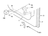
- FIG. 11 is a perspective view of a conventional slide door D as viewed from the inside of the vehicle. Further, the right side of FIG. 11 shows the front side of the vehicle and the left side shows the rear side of the vehicle, and the slide door D is slid open on the left side (rear side of the vehicle) of FIG. When the sliding door D is opened, the rotating arm 101 rotates to absorb the excess length by pulling up the electric wire W.
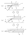
- FIG. 13 is a schematic diagram showing a positional relationship between the slide door D and the electric wire W when the slide door D is opened and closed.
- this positional relationship is shown in a sectional view of the slide door D along a cut surface parallel to the scuff trim ST on the vehicle floor.
- FIG. 13A shows the sliding door D in a state where it is opened to some extent.
- FIG. 13 (b) shows the sliding door D immediately after the protrusion at the time of opening or just before the full closing, and
- FIG. 13 (c) shows the sliding door D in the fully closed state.
- the contact angle ⁇ A becomes small and the electric wire W becomes the lower end of the door trim T.
- the portion extending in parallel tends to be caught on the lower edge of the door trim T. Stress is accumulated in the wire W thus caught, and the wire W climbs over the lower end edge of the door trim T at a stage when the stress reaches a certain level. And when the electric wire W climbs over the lower end edge of the door trim T at once, there is a problem that the vibration of the electric wire W at that time resonates as a noise to the passenger's ear.
- FIG. 14 is a view showing a kick-up portion provided at the lower end edge of the door trim T.
- a scuff trim ST is installed on the floor of the vehicle, and the kick-up portion K extends upward so that the lower end edge of the door trim T on the vehicle rear side is away from the scuff trim ST. It is a portion formed by rising at a kick-up angle ⁇ K.
- the kick-up portion K is made large to increase the gap Ar between the scuff trim ST and the door trim T. There are many. However, such an increase in the gap Ar has a problem that the appearance of the slide door D is lowered.
- the present invention provides a power supply structure for a slide door that can suppress abnormal noise caused by the vibration of an electric wire when the slide door is opened and closed and can improve the appearance of the slide door. Let it be an issue.
- the sliding door feeding structure according to claim 1 is a sliding door feeding structure in which an electric wire is routed between the vehicle body and the sliding door to feed power.
- an electric wire is routed between the vehicle body and the sliding door to feed power.
- the other end side holding portion Provided with one end side holding portion that holds one end side of the electric wire, and the other end side holding portion that holds the other end side of the electric wire, the other end side holding portion directly or on the slide door
- a rotating arm that is supported rotatably and holds the electric wire at the tip, and an urging means that urges the rotating arm in a direction to absorb the extra length of the electric wire.
- the tip of the rotating arm is a vehicle at a passing timing at which the electric wire passes over a predetermined position of the lower end edge of the door trim constituting the inside of the sliding door.
- the tip of the rotating arm is a vehicle at a passing timing at which the electric wire passes over a predetermined position of the lower end edge of the door trim constituting the inside of the sliding door.
- it is provided with obliquely.
- the power supply structure for a slide door according to claim 2 is the power supply structure for a slide door according to claim 1, wherein the rotating arm has a space in which the tip end portion is located outside the door trim of the slide door. It has a bent shape facing the side.
- the power supply structure for a slide door according to claim 3 is the power supply structure for a slide door according to claim 1, wherein the rotation arm is configured such that a rotation axis of the rotation arm is inclined with respect to the slide door. It is characterized by being.
- a power supply structure for a sliding door according to a fourth aspect is the power supply structure for a sliding door according to the first aspect, wherein the distal end of the rotating arm is positioned on the vehicle outer side than the door trim in the sliding door at the timing of getting over.
- An angle changing means for directing to the space side is further provided.
- the angle changing means may be configured to bend the rotating arm so that a tip of the rotating arm is directed to the space side.
- angle changing means tilts a pivot shaft of the pivot arm with respect to the slide door so that a tip of the pivot arm is moved to the space side. It may be directed.
- the electric wire is moved over the lower end edge of the door trim at the overpass timing. It is performed in an inclined state. As a result, when the slide door is slid, the wire is prevented from being caught on the lower edge of the door trim, and the electric wire can smoothly get over the lower edge of the door trim. Is also suppressed. Thereby, the abnormal noise resulting from the vibration of an electric wire etc. at the time of opening and closing of a slide door will be suppressed. Moreover, since the catch of an electric wire is suppressed, the kicking-up part mentioned above can be made small. As a result, the gap between the scuff trim on the vehicle floor and the door trim is suppressed, and as a result, the appearance of the sliding door is improved.
- the electric wire is connected to the lower end of the door trim including the above-mentioned transit timing. It can be reliably tilted with respect to the edge.
- the rotation arm of the rotation arm is inclined with respect to the door panel, the rotation arm is similar to the invention described in claim 2.
- the electric wire can be surely inclined with respect to the lower end edge of the door trim including the above-mentioned timing of getting over.
- the angle changing means directs the tip of the rotating arm toward the space at the overpass timing, so that it is possible to suppress friction between the slide door and the electric wire at times other than the overpass timing.
- the electric wire can smoothly get over the lower end edge of the door trim.
- a specific method of directing the tip of the second rotating arm toward the space by the angle changing means is a method of directing the tip of the rotating arm toward the space due to the structure of the shaft of the rotating arm itself.
- a method may be used in which an external force is applied to the rotating arm by a projection provided on the slide door, for example, and the tip of the rotating arm is directed to the space side.
- the angle changing portion by the angle changing means is the rotating shaft of the rotating arm, an angle changing structure that suppresses the strength reduction of the rotating arm itself is possible.
- FIG. 2 is a diagram showing a state in which the sliding door is moving backward while protruding toward the outside of the vehicle at the initial stage of opening the sliding door shown in FIG. 1. It is a figure which shows the kicking-up part provided in the lower end edge of the door trim. It is a figure which shows another example of the structure which inclines an electric wire. It is a figure which shows the structure of another example which inclined the electric wire to the door trim side. It is the perspective view which looked at the sliding door which concerns on the electric power feeding structure for sliding doors concerning 2nd Embodiment from the inner side of the vehicle.
- FIG. 2 is a diagram showing a state in which the sliding door is moving backward while protruding toward the outside of the vehicle at the initial stage of opening the sliding door shown in FIG. 1. It is a figure which shows the kicking-up part provided in the lower end edge of the door trim. It is a figure which shows another example of the structure which inclines an electric wire. It is a figure which shows the structure of another example which inclined
- FIG. 7 is a diagram showing a state in which the sliding door is moving backward while protruding toward the outside of the vehicle at the initial stage of opening the sliding door shown in FIG. 6. It is a figure which shows the angle change means which changes the angle with respect to the root arm part of a front-end
- the power supply structure 1 for a sliding door according to the present embodiment spans, for example, the vehicle body and the slide door D in order to connect the electronic device provided on the vehicle body side and the electronic device attached to the slide door D.
- the electric wire W is routed and power is supplied to an electronic device provided on the slide door D.
- the sliding door D includes a metal door outer panel P1 and a door inner panel P2 as the door panel P, and a synthetic resin door trim T provided facing the vehicle inner side of the door inner panel P2. ing.
- the electric wire W is comprised including the wire harness which consists of a some electric wire, and the connector was attached to the terminal, and the exterior member (for example, corrugated tube) which covers and protects this wire harness.
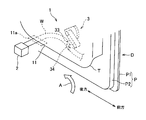
- FIG. 1 is a perspective view of the slide door D according to the first embodiment as viewed from the inside of the vehicle. 1 shows the fully closed state of the slide door D, the right side of FIG. 1 shows the front of the vehicle, and the left side shows the rear of the vehicle. D is slid open.
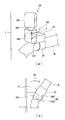
- FIG. 1A shows a perspective view of the slide door D, and FIG. 1B shows a second rotating arm 33 described later shown in FIG. 1A viewed from above. A plan view is shown.
- FIG. 2 is a view showing a state in which the slide door D is directed rearward while protruding toward the outside of the vehicle at the initial stage of opening the slide door D shown in FIG.
- the one end side holding portion 2 is provided in the vicinity of the floor of the vehicle main body, holds one end portion of the electric wire W in a freely swingable manner, and passes the electric wire W toward an electronic device such as a control device.
- This one end side holding part 2 can use what has the outer member fixed to a vehicle body, and the inner member rotatably supported by this outer member, for example, and electric wire W is held by the inner member.
- the electric wire W is inserted into the outer member and connected to the control device or the like.
- the other end side holding part 3 is pivoted to the base 31 fixed to the door inner panel P ⁇ b> 2, the first pivot arm 32 rotatably supported by the base 31, and the tip of the first pivot arm 32.
- the second rotating arm 33 that is freely supported, the tip holding portion 34 that is provided at the tip portion of the second turning arm 33 and holds the electric wire W, and the shaft portion of the first turning arm 32 are incorporated.
- a torsion coil spring (not shown) as urging means for urging the first rotating arm 32 against the base 31 is configured.
- the torsion coil spring urges the first rotating arm 32 counterclockwise in FIGS. 1 and 2, that is, the first torsion coil spring in the fully closed state of the slide door D shown in FIG. 1.
- the rotating arm 32 As the rotating arm 32 is urged counterclockwise, tension is applied to the electric wire W, and the sliding door D is opened, the electric wire W whose tension is lowered as the slide door D is opened is reduced by the first torsion coil spring.
- the rotating arm 32 rotates counterclockwise, and the electric wire W is pulled up by this rotation.
- the other end side holding part 3 functions to absorb the extra length of the electric wire W by the first rotating arm 32 urged by the torsion coil spring and prevent the electric wire W from drooping.
- the second rotating arm 33 has a bent shape whose tip is directed to the space located on the door trim T side of the sliding door D, that is, the door panel P side. Have.
- the electric wire W moves from the front end holding portion 34 toward the door panel P, and is then pulled and bent by the one end side holding portion 2, and the lower end edge of the door trim T
- the lower end edge 11 is dived in a state inclined with respect to 11.
- the electric wire W gets over the overpassing position 11a with the inclined posture.
- the wire W can be prevented from being caught on the lower end edge 11 of the door trim T at the time of getting over, and the electric wire W can smoothly get over the lower end edge 11 of the door trim T. Vibrations can be suppressed. Thereby, the abnormal noise resulting from the vibration of the electric wire W etc. at the time of this opening of the slide door D will be suppressed.
- the slide door D When the slide door D is closed, the slide door D protrudes toward the inside of the vehicle while heading forward of the vehicle immediately before reaching the fully closed state shown in FIG. At this time, the electric wire W gets over the lower end edge 11 of the door trim T to the door panel P side. Also at this time, the second rotating arm 33 having a bent shape suppresses the electric wire W from being caught on the lower end edge 11 of the door trim T, and thus the vibration of the electric wire W when the slide door D is closed, etc. An abnormal noise caused by the noise is also suppressed.
- FIG. 3 is a view showing a kick-up portion provided at the lower end edge 11 of the door trim T.
- a scuff trim ST is installed on the floor of the vehicle, and the kick-up portion K is located above the lower end edge 11 of the door trim T away from the scuff trim ST on the vehicle rear side. And a portion formed by rising at a kick-up angle ⁇ K.
- the kick-up portion K plays a role in helping the electric wire W get over the lower end edge 11 of the door trim T.
- the hooking of the electric wire W is suppressed as described above.
- the kick-up portion K in the present embodiment can be made smaller. As a result, the gap Ar between the scuff trim ST and the door trim T on the floor of the vehicle is suppressed, and as a result, the appearance of the slide door D is improved.
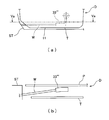
- FIG. 4 is a diagram showing another example of the structure in which the electric wire W is inclined.
- FIG. 4A shows a second turning arm 33 ′ having a bent shape facing the door panel P at the base near the turning shaft.
- FIG. 4B shows a second rotating arm 33 ′′ whose rotating shaft itself is inclined toward the door panel P. Any of the second rotating arms 33 ′ and 33 ′′ can By inclining W as described above, it is possible to smoothly get over and over the electric wire W at the overpass position 11a.
- the structure for inclining the electric wire W as described above is not limited to the structure in which the second rotating arm is bent as described above, or the structure in which the rotating shaft is inclined.
- Examples include a structure in which the first rotation arm 32 on which the arm is supported is bent, and a structure in which the rotation axis is inclined. It goes without saying that even if the structure relating to the first rotating arm 32 is such a structure, the electric wire W can be inclined as described above and the electric wire W can be smoothly moved over the position 11a.
- the direction of inclination of the electric wire W is illustrated as an example of the direction of inclination of the electric wire W.
- the direction of inclination of the electric wire W is not limited to this, and may be the direction inclined toward the door trim T side.
- FIG. 5 is a diagram showing another example of the structure in which the electric wire W is inclined toward the door trim T side.
- FIG. 5A shows a side view of the sliding door D as viewed from the inside of the vehicle, and
- FIG. 5B shows a cross-sectional view taken along the line Va in FIG. 5A. Has been.
- the second rotating arm 33 ′′ ′′ has a bent shape with the tip portion facing the door trim T side. Even with this bent shape, the electric wire W gets over the lower end edge 11 of the door trim T in an inclined state. Therefore, even with this other example structure, the wire W can be smoothly passed over.
- FIG. 6, FIG. 7, and FIG. The second embodiment is equivalent to the first embodiment described above except for the first rotating arm and the second rotating arm. Therefore, in the following, description of the second embodiment will be omitted with respect to the same points as the first embodiment, and description will be made focusing on differences from the first embodiment.
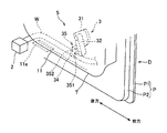
- FIG. 6 is a perspective view of the slide door D according to the power supply structure 5 for the slide door according to the second embodiment as viewed from the inside of the vehicle. 6 shows the fully closed state of the slide door D, and the right side of FIG. 6 shows the front side of the vehicle and the left side shows the rear side of the vehicle. D is slid open.
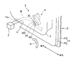
- FIG. 7 is a view showing a state in which the slide door D is directed rearward while protruding toward the outside of the vehicle at the initial stage of opening of the slide door D shown in FIG. 6.
- the second rotating arm 35 supported by the first rotating arm 32 includes a root arm portion 351 and a tip arm portion 352.
- the distal end arm portion 352 is provided with the distal end holding portion 34, and the distal end arm portion 352 is rotatably connected to the root arm portion 351 by a connecting shaft 353 (shown in FIG. 8).
- the connecting shaft 353 includes a torsion coil spring (not shown) as an urging means. The torsion coil spring urges the tip arm portion 352 so that the extending direction of the tip arm portion 352 and the extending direction of the root arm portion 351 are aligned and the second rotating arm 35 is linear. ing.
- the angle changing means described later changes the angle of the tip arm portion 352 with respect to the root arm portion 351 at the overcoming timing when the electric wire W reaches the overpass position 11a. 35 is bent. Thereby, at the boarding timing, the tip of the second turning arm 35, that is, the tip arm portion 352 is directed toward the space located on the door trim T side of the slide door D, that is, the door panel P side.
- FIG. 8 is a view showing angle changing means for changing the angle of the tip arm portion 352 with respect to the root arm portion 351.
- FIG. 8A shows a perspective view of the configuration of the angle changing means as viewed from the door panel P side to the door trim T side.
- FIG. 8B shows a plan view of the configuration shown in FIG. 8A as viewed from above.
- the angle changing means includes a second rotating arm 35 in which the root arm portion 351 and the tip arm portion 352 are connected, and a protrusion 4 that protrudes from the door trim T toward the door panel P and presses the tip arm portion 352. It consists of.
- the first rotating arm 32 and the second rotating arm 35 accompanying the pulling up of the electric wire W and the protrusion of the sliding door D to the outside of the vehicle are shown in FIGS.
- the electric wire W reaches the shown overpass position 11a.
- the tip of the protrusion 4 comes into contact with the tip arm portion 352 of the second rotating arm 35 and presses the tip arm portion 352 toward the door panel P.
- the tip arm portion 352 rotates in the arrow B1 direction.
- the electric wire W moves from the tip holding portion 34 to the door panel P side as shown in FIG. It is pulled and bent, and the lower end edge 11 of the door trim T is moved over the lower end edge 11 while being inclined.
- the wire W can be prevented from being caught on the lower end edge 11 of the door trim T at the time of getting over, and the electric wire W can smoothly get over the lower end edge 11 of the door trim T. Vibrations can be suppressed. Thereby, the abnormal noise resulting from the vibration of the electric wire W etc. at the time of this opening of the slide door D will be suppressed.
- the slide door D When the slide door D is closed, the slide door D protrudes toward the inside of the vehicle while heading forward of the vehicle immediately before reaching the fully closed state shown in FIG. At this time, the electric wire W gets over the lower end edge 11 of the door trim T to the door panel P side. Also at this time, the hook of the electric wire W to the lower end edge 11 of the door trim T is suppressed by the rotation of the tip arm portion 352 by the protrusion 4, and as a result, the vibration of the electric wire W when the slide door D is closed, etc. An abnormal noise caused by the noise is also suppressed.
- the tip of the second turning arm 35 is directed to the door panel P side at the transit timing, while suppressing the friction between the door trim T and the door panel P and the electric wire W at times other than the transit timing, The electric wire W can smoothly get over the lower end edge 11 of the door trim T.
- the direction of the inclination of the electric wire W is not limited to the door panel P side, and the inclination of the electric wire W is similar to that of the other structure in the first embodiment shown in FIG. It goes without saying that the direction may be the door trim T side. In this case, when a protrusion is employed as the angle changing means, the protrusion protrudes from the door panel P toward the door trim T.
- the angle changing portion by the protrusion 4 is the tip arm portion 352 that is a part of the second rotating arm 35, and therefore the angle changing structure that minimizes the angle changing portion is necessary. It has been realized.
- FIG. 9 is a diagram showing another example of the angle changing means.
- FIG. 9A shows a perspective view of another example of the angle changing means as viewed from the door panel P side to the door trim T side.
- FIG. 9B shows a plan view of the configuration shown in FIG. 9A as viewed from above.
- the first rotating arm 36 includes a root arm portion 361 and a tip arm portion 362.
- the root arm portion 361 is rotatably supported by the base 31 shown in FIG. 6, and the tip arm portion 362 is rotatably connected to the root arm portion 361, and at the tip thereof,
- the 2nd rotation arm 37 is supported so that rotation is possible.
- the electric wire W is held by a tip holding portion 34 provided at the tip of the second rotating arm 37.
- the connecting shaft 363 that connects the base arm portion 361 and the tip arm portion 362 in the first rotating arm 36 is an axis orthogonal to the rotating shaft 371 of the second rotating arm 37.
- the connecting shaft 363 incorporates a torsion coil spring (not shown) as urging means. This torsion coil spring urges the tip arm portion 362 in a direction in which the outer surface of the root arm portion 361 and the outer surface of the tip arm portion 362 are aligned and the first rotating arm 36 is linear. .
- the angle changing means of this other example includes a first rotating arm 36 in which a root arm portion 361 and a tip arm portion 362 are connected, and a second rotating arm 37 protruding from the door trim T toward the door panel P, as will be described later. And a protrusion 4 that presses against.
- the electric wire W is the lower end edge of the door trim T in the same manner as the electric wire W in the second embodiment shown in FIG. In this state, the lower end edge 11 is crossed.
- the wire W can be prevented from being caught on the lower end edge 11 of the door trim T at the time of getting over, and the electric wire W can smoothly get over the lower end edge 11 of the door trim T. Vibrations can be suppressed. Thereby, the abnormal noise resulting from the vibration of the electric wire W etc. at the time of this opening of the slide door D will be suppressed.
- the kick-up portion K (see FIG. 3) is reduced to suppress the gap Ar between the scuff trim ST and the door trim T, and the sliding door D The appearance can be improved.
- the tip of the second rotating arm 37 is directed to the door panel P side at the timing of getting over as in the second embodiment described above.
- the lower end edge 11 of the door trim T can be smoothly moved over the electric wire W while suppressing friction between the door panel P and the electric wire W.
- the angle changing portion by the protrusion 4 is the rotating shaft 371 of the second rotating arm 37 with respect to the first rotating arm 36, so the strength of the second rotating arm 37 itself is reduced. An angle changing structure that suppresses this is realized.
- FIG. 10 is a diagram showing still another example of the angle changing means.
- the rotation shaft 381 that rotatably supports the first rotation arm 38 is supported by the bearing 311 provided on the base 31 so as to be tiltable with respect to the base 31.
- a second turning arm 39 is rotatably supported at the tip of the first turning arm 38, and the electric wire W is a tip holding portion provided at the tip of the second turning arm 39. 34.
- the rotation shaft 381 of the first rotation arm 38 is biased in a direction orthogonal to the base 31 by a spring (not shown) built in the bearing 311.
- the angle changing means of this further another example includes a rotation shaft 381 of the first rotation arm 38 and a protrusion 4 that protrudes from the door trim T toward the door panel P and presses the second rotation arm 39 as described later. Composed.
- the angle changing means when the slide door D is opened, the first turning arm 38 and the second turning arm 39 are turned when the electric wire W is pulled up, and the sliding door D is moved to the outside of the vehicle.
- the protrusion 4 pushes the second rotating arm 39 toward the door panel P at the overpass timing when the electric wire W reaches the overpass position 11a shown in FIGS.
- the rotation shaft 381 of the first rotation arm 38 is inclined in the direction of the arrow B3 with respect to the base 31, and as a result, the tip of the second rotation arm 39 is directed toward the door panel P.
- the electric wire W is similar to the electric wire W in the second embodiment shown in FIG. In this state, the lower end edge 11 is crossed. As a result, the wire W can be prevented from being caught on the lower end edge 11 of the door trim T at the time of getting over, and the electric wire W can smoothly get over the lower end edge 11 of the door trim T. Vibrations can be suppressed. Thereby, the abnormal noise resulting from the vibration of the electric wire W etc. at the time of this opening of the slide door D will be suppressed.
- the kicking portion K (see FIG. 3) is reduced to suppress the gap Ar between the scuff trim ST and the door trim T, and the sliding door The appearance of D can be improved.
- the tip of the second turning arm 39 is directed to the door panel P side at the overpass timing as in the above-described second embodiment.
- the lower end edge 11 of the door trim T can be smoothly moved over the electric wire W while suppressing the friction between the door trim T and the door panel P and the electric wire W.
- the angle changing portion by the protrusion 4 is the rotation shaft 381 of the first rotation arm 38 with respect to the base 31, the arm structure including the first rotation arm 38 and the second rotation arm 39.
- the angle changing structure is realized without changing the structure itself as a simple rotating structure.
- the protrusion 4 protruding from the door trim T is used to press the second rotating arm.
- the angle change means said to this invention is not restricted to this structure.
- the angle changing means referred to in the present invention is, for example, at a rotation angle corresponding to the timing of getting over the electric wire W reaching the ride-over position 11a on the turn shaft of the first turn arm or the turn shaft of the second turn arm.
- a configuration in which a cam mechanism for tilting the first rotation arm or the second rotation arm is attached may be used.
- the rotating arm has a bent shape
- the tip is A configuration that always inclines including the timing of overriding (first embodiment) and a configuration that tilts the tip of the rotating arm at the timing of overriding by the angle changing means (second embodiment) are illustrated.
- first embodiment the configuration in which the tip of the rotating arm is inclined with respect to the vehicle front-rear direction
- second embodiment the configuration in which the tip of the rotating arm is inclined with respect to the vehicle front-rear direction
- the rotating arm can be used over an arbitrary period as long as it is at least during the period including the above timing of overriding.
- the tip may be inclined.
- a configuration in which one end of the rotating arm is bent as a configuration in which the tip of the rotating arm is inclined with respect to the vehicle front-rear direction (first) Embodiment) and a configuration (second embodiment) in which one part of the rotating arm is bent by the angle changing means are illustrated.
- the configuration in which the tip of the rotating arm is inclined with respect to the vehicle front-rear direction is not limited to these configurations.
- the number and location of the bent portions may be any number or location.
- the base 31 of the other end side holding portion 3 is fixed to the door inner panel P2 of the sliding door D, but the base 31 is attached to the door trim T. It may be fixed.
- the first rotating arm 32 rotates downward, and the maximum urging force is applied to the first rotating arm 32 from the urging means (torsion coil spring).
- the 1st rotation arm 32 may rotate against the urging
Landscapes
- Engineering & Computer Science (AREA)
- Mechanical Engineering (AREA)
- Electric Cable Arrangement Between Relatively Moving Parts (AREA)
Abstract
スライドドアの開閉時に電線の振動等に起因した異音が抑制されるとともに、スライドドアの見栄えを向上させることができるスライドドア用給電構造を提供する。電線(W)の他端側を保持する他端側保持部(3)を備え、他端側保持部(3)は、スライドドア(D)に直接又は間接に回動自在に支持されて先端部に電線(W)を保持する第1及び第2回動アーム(32,33)と、電線(W)の余長を吸収する方向に第1回動アーム(32)を付勢する付勢手段と、を有して構成され、スライドドア(D)がスライド移動される際にこのスライドドア(D)の車内側を構成するドアトリム(T)の下端縁(11)のうちの所定の乗越え位置(11a)を電線Wが乗越える乗越タイミングにおいて、第2回動アーム(33)の先端が車両前後方向に対して傾斜して設けられている。
Description
本発明は、車両本体とスライドドアとに亘って電線を配索して給電するスライドドア用給電構造に関するものである。
従来、自動車の車両本体にスライド自在に支持されたスライドドアが利用されており、このスライドドアには、ドアロックスイッチやウィンドウガラス開閉スイッチ、カーテシランプ等の電子機器が取り付けられている。このため、スライドドアが設けられた車両には、スライドドアに取り付けられた電子機器と車体側に設けられた制御装置等の電子機器とを接続するために、車両本体とスライドドアとに亘って電線(ワイヤハーネス)を配索して給電する給電構造が用いられている。このような給電構造としては、電線を保持するとともに、ドアパネルに回動自在に軸支されて電線の余長吸収方向に付勢されたアーム部材を備えたものが提案されている(例えば、特許文献1参照)。
上記のようなアーム部材を有する従来のスライドドア用給電構造について説明する。図11に示すように、従来のスライドドア用給電構造は、スライドドアDのドアパネルPとドアトリムTとの間にあって、回動自在に支持される回動アーム101の先端に電線Wが保持されている。電線Wの車両本体側の一端は、この車両本体側に設けられた固定具102に固定されている。尚、図11は、従来のスライドドアDを車両の内側から見た斜視図である。また、図11の右側が車両前方、左側が車両後方を示すものであり、この図11の左側(車両後方)にスライドドアDがスライド開放されるようになっている。スライドドアDの開放時には、回動アーム101が回動して電線Wを引き上げることで余長分を吸収する。
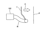
また、スライドドアDの開放時には、矢印Cが示すように、スライドドアDは、車両の外側に向かって突出しつつ後方へと向かう。このときには、図12に示すように、電線WのうちスライドドアDのドアパネルPとドアトリムTとの間に位置する部分が、矢印C方向へのスライドドアDの突出の際に、ドアトリムTの下端縁を車両本体側へと乗越える。図12は、図11に矢視Vb線で示す断面図である。
ところで、上述した従来のスライドドア用給電構造では、スライドドアDの開閉の際に、スライドドアDと電線Wとの位置関係は次のようなものになる。図13は、スライドドアDの開閉の際における、スライドドアDと電線Wとの位置関係を示す模式図である。この図13には、この位置関係が、スライドドアDの、車両のフロア上のスカッフトリムSTと平行な切断面に沿った断面図で示されている。図13(a)には、ある程度開いた状態のスライドドアDが示されている。また、図13(b)には、開放時における突出直後、あるいは全閉直前におけるスライドドアDが示され、図13(c)には全閉状態のスライドドアDが示されている。
図13に示されているように、スライドドアDの開放時には、その開放動作に伴い、スライドドアDにおいて、電線WとドアトリムTとの当接部PAが車両前方へ移動しつつ、電線WとドアトリムTとの当接角度θAが大きくなっていく。逆に、スライドドアDが閉じられる時には、その閉動作に伴い、スライドドアDにおいて当接部PAが車両後方へ移動しつつ当接角度θAが小さくなっていく。
そして、図13(c)に示されている全閉状態への移行の際、あるいは、この全閉状態から開放へと向かう際に、当接角度θAが小さくなって電線WがドアトリムTの下端縁と略平行に延びている際に、その平行に延びている部分がドアトリムTの下端縁に引っ掛かりがちとなる。このように引っ掛かった電線Wには応力が溜まり、その応力がある程度のレベルに達した段階で電線WがドアトリムTの下端縁を一気に乗越えることとなる。そして、このように電線WがドアトリムTの下端縁を一気に乗越えると、その際の電線Wの振動等が、搭乗者の耳に異音として響くという問題がある。
ここで、ドアトリムTの下端縁における車両後方側には、以下に説明する蹴上がり部が設けられている。図14は、ドアトリムTの下端縁に設けられた蹴上がり部を示す図である。この図14に示されているように、車両のフロアにはスカッフトリムSTが設置されており、蹴上がり部Kは、ドアトリムTにおける車両後方側の下端縁が、スカッフトリムSTから離れる上方へと蹴上がり角度θKで立ち上って形成された部分である。
従来、スライドドアDの開閉時における電線WとドアトリムTの下端縁との引っ掛かりを抑えるために、蹴上がり部Kを大きくとって、スカッフトリムSTとドアトリムTとの隙間Arを増大させていることが多い。しかしながら、このような隙間Arの増大には、スライドドアDの見栄えを低下させてしまうという問題がある。
これらの事情に鑑み、本発明は、スライドドアの開閉時に電線の振動等に起因した異音が抑制されるとともに、スライドドアの見栄えを向上させることができるスライドドア用給電構造を提供することを課題とする。
上記課題を解決するために請求項1に記載のスライドドア用給電構造は、車両本体とスライドドアとに亘って電線を配索して給電するスライドドア用給電構造であって、前記車両本体に設けられて前記電線の一端側を保持する一端側保持部と、前記電線の他端側を保持する他端側保持部と、を備え、前記他端側保持部は、前記スライドドアに直接又は間接に回動自在に支持されて先端部に前記電線を保持する回動アームと、前記電線の余長を吸収する方向に前記回動アームを付勢する付勢手段と、を有して構成され、前記スライドドアがスライド移動される際に該スライドドアの車内側を構成するドアトリムの下端縁のうちの所定の乗越え位置を前記電線が乗越える乗越タイミングにおいて、前記回動アームの先端が車両前後方向に対して傾斜して設けられていることを特徴とする。
請求項2に記載のスライドドア用給電構造は、請求項1記載のスライドドア用給電構造において、前記回動アームは、前記先端部が、前記スライドドアにおける前記ドアトリムよりも車外側に位置する空間側に向いた屈曲形状を有していることを特徴とする。
請求項3に記載のスライドドア用給電構造は、請求項1記載のスライドドア用給電構造において、前記回動アームは、該回動アームの回動軸が、前記スライドドアに対して傾斜していることを特徴とする。
請求項4に記載のスライドドア用給電構造は、請求項1記載のスライドドア用給電構造において、前記乗越タイミングで前記回動アームの先端を、前記スライドドアにおける前記ドアトリムよりも車外側に位置する空間側に向ける角度変更手段を、更に備えたことを特徴とする。
また、請求項4記載のスライドドア用給電構造において、前記角度変更手段は、前記回動アームを屈曲させることで該回動アームの先端を前記空間側に向けるものであってもよい。
また、請求項4記載のスライドドア用給電構造において、前記角度変更手段は、前記回動アームの回動軸を、前記スライドドアに対して傾けることで前記回動アームの先端を前記空間側に向けるものであってもよい。
請求項1に記載された発明によれば、回動アームの先端が上記の空間側に向いているので、電線の、乗越タイミングでのドアトリムの下端縁の乗越えが、電線がその下端縁に対して傾斜した状態で行われる。その結果、スライドドアがスライド移動される際の、ドアトリムの下端縁への電線の引っ掛かりが抑制され、電線は、ドアトリムの下端縁をスムーズに乗越えることができ、その乗越え時の電線の振動等も抑えられる。これにより、スライドドアの開閉時に電線の振動等に起因した異音が抑制されることとなる。また、電線の引っ掛かりが抑制されることから、その分、上述した蹴上がり部を小さくすることができる。その結果、車両のフロア上のスカッフトリムとドアトリムとの隙間が抑えられ、延いては、スライドドアの見栄えが向上されることとなる。
請求項2に記載された発明によれば、前記回動アームは、前記先端部が前記空間側に向いた屈曲形状を有しているので、電線を、上記の乗越タイミングを含めてドアトリムの下端縁に対して確実に傾斜させることができる。
請求項3に記載された発明によれば、前記回動アームは、該回動アームの回動軸が、前記ドアパネルに対して傾斜しているので、請求項2に記載された発明と同様に、電線を、上記の乗越タイミングを含めてドアトリムの下端縁に対して確実に傾斜させることができる。
請求項4に記載された発明によれば、乗越タイミングで角度変更手段が回動アームの先端を上記空間側に向けるので、その乗越タイミング以外のときのスライドドアと電線との擦れ等を抑えつつ、電線に、ドアトリムの下端縁をスムーズに乗越えさせることができる。尚、角度変更手段による、第2回動アームの先端を上記空間側に向ける具体的な方法としては、回動アームの軸自体の構造により、回動アームの先端を上記空間側に向ける方法であってもよく、又は、例えばスライドドアに設けられた突起等で回動アームに外力を加えることで回動アームの先端を上記空間側に向ける方法であってもよい。
また、請求項4に記載された発明において、角度変更手段による角度変更部位が回動アーム自体であれば、その角度変更部位を必要最小限に抑えた角度変更構造が可能となる。
また、請求項4に記載された発明において、角度変更手段による角度変更部位が回動アームの回動軸であれば、回動アーム自体の強度低下を抑えた角度変更構造が可能となる。
本発明の第1実施形態に係るスライドドア用給電構造を図1及び図2を用いて説明する。本実施形態のスライドドア用給電構造1は、例えば、車両本体側に設けられた電子機器と、スライドドアDに取り付けられた電子機器と、を接続するために車両本体とスライドドアDとに亘って電線Wを配索するとともに、スライドドアDに設けられた電子機器に給電するためのものである。スライドドアDは、ドアパネルPとしての金属製のドアアウタパネルP1及びドアインナパネルP2と、このドアインナパネルP2の車内側に対向して設けられる合成樹脂製のドアトリムTと、を有して構成されている。また、電線Wは、複数の電線からなり端末にコネクタが取り付けられたワイヤハーネスと、このワイヤハーネスを覆って保護する外装部材(例えば、コルゲートチューブ)と、を含んで構成されている。
スライドドア用給電構造1は、車両本体に設けられて電線Wの一端側を保持する一端側保持部2と、ドアパネルPとドアトリムTとの間に設けられて電線Wの他端側を保持する他端側保持部3と、を備えて構成されている。尚、図1は、第1実施形態のスライドドアDを車両の内側から見た斜視図である。また、図1は、スライドドアDの全閉状態を示すとともに、図1の右側が車両前方、左側が車両後方を示すものであり、この全閉状態から図の左側(車両後方)にスライドドアDがスライド開放されるようになっている。図1(a)には、スライドドアDの斜視図が示されており、図1(b)には、図1(a)に示されている後述の第2回動アーム33を上方から見た平面図が示されている。図2は、図1に示されているスライドドアDの開放の初めの段階で、このスライドドアDが車両の外側へと突出しながら後方へと向かっている状態を示す図である。
一端側保持部2は、車両本体におけるフロア近傍に設けられ、電線Wの一端部を搖動自在に保持するとともに、この電線Wを制御装置等の電子機器に向かって挿通させている。この一端側保持部2は、例えば、車両本体に固定されるアウター部材と、このアウター部材に回転自在に支持されるインナー部材と、を有したものが利用でき、インナー部材に電線Wが保持されるとともに、この電線Wがアウター部材に挿通されて制御装置等に接続されている。
他端側保持部3は、ドアインナパネルP2に固定されるベース31と、このベース31に回動自在に支持される第1回動アーム32と、第1回動アーム32の先端に回動自在に支持される第2回動アーム33と、第2回動アーム33の先端部に設けられて電線Wを保持する先端保持部34と、第1回動アーム32の軸部に内蔵されてベース31に対して第1回動アーム32を付勢する付勢手段としてのねじりコイルばね(不図示)と、を有して構成されている。このねじりコイルばねは、図1及び図2における反時計回りに第1回動アーム32を付勢しており、即ち、図1に示すスライドドアDの全閉状態において、ねじりコイルばねによって第1回動アーム32が反時計回りに付勢され、電線Wにテンションが作用し、スライドドアDが開放されるにつれて、垂れ下がろうとしてテンションが低下する電線Wに対し、ねじりコイルばねによって第1回動アーム32が反時計回りに回動し、この回動によって電線Wを引き上げる。このように他端側保持部3は、ねじりコイルばねで付勢された第1回動アーム32によって電線Wの余長を吸収し、電線Wの垂れ下がりを防止するように機能するものである。
ここで、スライドドアDの開放時には、図2中の矢印Aが示すように、スライドドアDは、車両の外側に向かって突出しつつ後方へと向かう。そして、この時には、電線WのうちスライドドアDのドアパネルPとドアトリムTとの間の空間内に位置する部分は、他端側保持部3によって車両前方側の斜め上方に引き上げられる。そして、この引き上げとスライドドアDの突出とにより、上記空間内の電線Wは、その一端側保持部2寄りの一部が、ドアトリムTの下端縁11のうち、所定の乗越え位置11aに達して、図2に示されているようにこの乗越え位置11aを車両本体側へと乗越える。
また、本実施形態のスライドドア用給電構造1では、第2回動アーム33は、その先端部が、スライドドアDにおけるドアトリムT側に位置する空間側、即ちドアパネルP側に向いた屈曲形状を有している。これにより、電線Wは、図1及び図2に示されているように、先端保持部34からドアパネルP側へと向かい、その後、一端側保持部2に引かれて折れ曲がり、ドアトリムTの下端縁11に対して傾斜した状態でその下端縁11を潜る。その結果、上記の乗越えタイミングでは、電線Wは、このように傾斜した姿勢のまま乗越え位置11aを乗越えることとなる。その結果、この乗越え時の、ドアトリムTの下端縁11への電線Wの引っ掛かりが抑制され、電線Wは、ドアトリムTの下端縁11をスムーズに乗越えることができ、その乗越え時の電線Wの振動等も抑えられる。これにより、スライドドアDのこの開放時に電線Wの振動等に起因した異音が抑制されることとなる。
スライドドアDが閉じられるときには、図1に示されている全閉状態へと至る直前に、スライドドアDは、車両の前方へと向かいつつ車両の内側に向かって突出する。この時には、電線Wは、ドアトリムTの下端縁11をドアパネルP側へと乗越える。この際にも、屈曲形状を有する第2回動アーム33により、ドアトリムTの下端縁11への電線Wの引っ掛かりが抑制され、延いては、スライドドアDが閉じられる時の電線Wの振動等に起因した異音も抑制されることとなる。
ここで、ドアトリムTの下端縁11における車両後方側には、以下に説明する蹴上がり部が設けられている。図3は、ドアトリムTの下端縁11に設けられた蹴上がり部を示す図である。この図3に示されているように、車両のフロアにはスカッフトリムSTが設置されており、蹴上がり部Kは、ドアトリムTの下端縁11が、車両後方側でスカッフトリムSTから離れる上方へと蹴上がり角度θKで立ち上って形成された部分である。
この蹴上がり部Kは、電線Wの、ドアトリムTの下端縁11の乗越えを助ける役割を果たすが、本実施形態によれば、上述したように電線Wの引っ掛かりが抑制されることから、例えば図14に示されている従来のスライドドアDにおける蹴上がり部Kに比べて、本実施形態における蹴上がり部Kを小さくすることができる。その結果、車両のフロア上のスカッフトリムSTとドアトリムTとの隙間Arが抑えられ、延いては、スライドドアDの見栄えが向上されることとなる。
ここで、電線Wを上記のように傾斜させる構造としては、図1及び図2に示されている第2回動アーム33の屈曲形状の他に、次のような構造が別例として挙げられる。
図4は、電線Wを傾斜させる構造の別例を示す図である。図4(a)には、回動軸近傍の根元でドアパネルP側に向いた屈曲形状を有した第2回動アーム33’が示されている。また、図4(b)には、回動軸自体がドアパネルP側に傾いた第2回動アーム33”が示されている。何れの第2回動アーム33’,33”によっても、電線Wを上記のように傾斜させることで、電線Wに乗越え位置11aをスムーズに乗越えさせることができる。
さらに、電線Wを上記のように傾斜させる構造としては、上記のように第2回動アームを屈曲形状とした構造や、その回動軸を傾けた構造に限るものではなく、第2回動アームが支持される第1回動アーム32を屈曲形状とした構造や、その回動軸を傾けた構造も挙げられる。第1回動アーム32にかかる構造をこのような構造としても、同様に、電線Wを上記のように傾斜させて、電線Wに乗越え位置11aをスムーズに乗越えさせることができることは言うまでもない。
また、ここまでに述べた第1実施形態およびその別例では、電線Wの傾斜の向きの一例として、ドアパネルP側に傾いた向きが例示されている。しかしながら、この電線Wの傾斜の向きは、これに限るものではなく、ドアトリムT側に傾いた向きであってもよい。
図5は、電線WをドアトリムT側に傾けた、別例の構造を示す図である。図5(a)には、車内側から見たスライドドアDの側面図が示されており、図5(b)には、図5(a)中に矢視Va線で示す断面図が示されている。
この図5に示されている別例の構造では、第2回動アーム33’’’は、その先端部がドアトリムT側に向いた屈曲形状を有している。この屈曲形状によっても、電線Wは、ドアトリムTの下端縁11を傾斜した状態で乗越えることとなる。従って、この別例の構造によっても、この電線Wの乗越えをスムーズなものとすることができる。
次に、本発明の第2実施形態に係るスライドドア用給電構造を図6、図7、及び図8を用いて説明する。尚、この第2実施形態は、第1回動アーム及び第2回動アームを除いて、上述した第1実施形態と同等なものとなっている。そこで、以下では、第2実施形態について、第1実施形態と同等な点については説明を省略し、第1実施形態との相違点に注目した説明を行う。
図6は、第2実施形態に係るスライドドア用給電構造5に係るスライドドアDを車両の内側から見た斜視図である。また、図6は、スライドドアDの全閉状態を示すとともに、図6の右側が車両前方、左側が車両後方を示すものであり、この全閉状態から図の左側(車両後方)にスライドドアDがスライド開放されるようになっている。図7は、図6に示されているスライドドアDの開放の初めの段階で、このスライドドアDが車両の外側へと突出しながら後方へと向かっている状態を示す図である。
本実施形態のスライドドア用給電構造5では、第1回動アーム32に支持される第2回動アーム35が根元アーム部分351と先端アーム部分352とを備えている。先端アーム部分352には上記の先端保持部34が設けられており、この先端アーム部分352が、根元アーム部分351に、連結軸353(図8に図示)によって回動自在に連結されている。また、この連結軸353には付勢手段としてのねじりコイルばね(不図示)が内蔵されている。このねじりコイルばねは、先端アーム部分352の延在方向と根元アーム部分351の延在方向とが揃って、第2回動アーム35が直線状となる向きに、先端アーム部分352を付勢している。
そして、電線Wによる上記の乗越えに当たり、電線Wが乗越え位置11aに達する乗越タイミングで、後述の角度変更手段が、先端アーム部分352の根元アーム部分351に対する角度を変更することで第2回動アーム35を屈曲させる。これにより、乗越タイミングでは、第2回動アーム35の先端、即ち先端アーム部分352が、スライドドアDにおけるドアトリムT側に位置する空間側、即ちドアパネルP側に向けられる。
図8は、先端アーム部分352の根元アーム部分351に対する角度を変更する角度変更手段を示す図である。図8(a)には、角度変更手段の構成を、ドアパネルP側からドアトリムT側へと見た斜視図が示されている。また、図8(b)には、図8(a)に示されている構成を上方から見た平面図が示されている。
本実施形態では、角度変更手段は、根元アーム部分351と先端アーム部分352とが連結された第2回動アーム35と、ドアトリムTからドアパネルPに向かって突出し先端アーム部分352を押圧する突起4とで構成される。スライドドアDの開放時には、電線Wの引き上げに伴う第1回動アーム32及び第2回動アーム35の回動と、スライドドアDの、車両外側への突出とにより、図1や図2に示されている乗越え位置11aに電線Wが達する。そして、その乗越タイミングで、突起4の先端が第2回動アーム35の先端アーム部分352に接触し、その先端アーム部分352をドアパネルP側へと押圧する。これにより、先端アーム部分352が矢印B1方向へと回動する。
乗越タイミングでの先端アーム部分352のこのような回動により、電線Wは、図7に示されているように、先端保持部34からドアパネルP側へと向かい、その後、一端側保持部2に引かれて折れ曲がり、ドアトリムTの下端縁11に対して傾斜した状態でその下端縁11を乗越えることとなる。その結果、この乗越え時の、ドアトリムTの下端縁11への電線Wの引っ掛かりが抑制され、電線Wは、ドアトリムTの下端縁11をスムーズに乗越えることができ、その乗越え時の電線Wの振動等も抑えられる。これにより、スライドドアDのこの開放時に電線Wの振動等に起因した異音が抑制されることとなる。
スライドドアDが閉じられるときには、図6に示されている全閉状態へと至る直前に、スライドドアDは、車両の前方へと向かいつつ車両の内側に向かって突出する。この時には、電線Wは、ドアトリムTの下端縁11をドアパネルP側へと乗越える。この際にも、突起4による先端アーム部分352の回動により、ドアトリムTの下端縁11への電線Wの引っ掛かりが抑制され、延いては、スライドドアDが閉じられる時の電線Wの振動等に起因した異音も抑制されることとなる。
さらに、本実施形態でも、電線Wの引っ掛かりが抑制されることを見越して、上述した蹴上がり部K(図3参照)を小さくすることができる。これにより、本実施形態でも、車両のフロア上のスカッフトリムSTとドアトリムTとの隙間Arが抑えられ、延いては、スライドドアDの見栄えが向上されることとなる。
また、本実施形態では、乗越タイミングで第2回動アーム35の先端がドアパネルP側に向けられるので、その乗越タイミング以外のときのドアトリムTやドアパネルPと電線Wとの擦れ等を抑えつつ、電線Wに、ドアトリムTの下端縁11をスムーズに乗越えさせることができる。
尚、本実施形態でも、電線Wの傾斜の向きは、ドアパネルP側に限られるものではなく、図5に示されている第1実施形態における別例の構造と同様に、電線Wの傾斜の向きを、ドアトリムT側としてもよいことは言うまでもない。この場合、角度変更手段として突起を採用するときには、その突起は、ドアパネルPからドアトリムTに向かって突出したものとなる。
また、本実施形態では、突起4による角度変更部位が第2回動アーム35の一部である先端アーム部分352となっているので、その角度変更部位を必要最小限に抑えた角度変更構造が実現されている。
次に、角度変更手段の別例について図9を用いて説明する。
図9は、角度変更手段の別例を示す図である。図9(a)には、別例の角度変更手段を、ドアパネルP側からドアトリムT側へと見た斜視図が示されている。また、図9(b)には、図9(a)に示されている構成を上方から見た平面図が示されている。
この別例の角度変更手段では、第1回動アーム36が根元アーム部分361と先端アーム部分362とを備えている。根元アーム部分361は、図6に示されているベース31に回動自在に支持されており、先端アーム部分362は、この根元アーム部分361に回動自在に連結されるとともに、その先端に、第2回動アーム37を回動自在に支持している。電線Wは、この第2回動アーム37の先端に設けられた先端保持部34に保持されている。
第1回動アーム36において根元アーム部分361と先端アーム部分362とを連結している連結軸363は、第2回動アーム37の回動軸371に直交する軸となっている。この連結軸363には付勢手段としてのねじりコイルばね(不図示)が内蔵されている。このねじりコイルばねは、根元アーム部分361の外表面と先端アーム部分362の外表面とが揃って、第1回動アーム36が直線状となる向きに、先端アーム部分362を付勢している。
この別例の角度変更手段は、根元アーム部分361と先端アーム部分362とが連結された第1回動アーム36と、ドアトリムTからドアパネルPに向かって突出し第2回動アーム37を後述するように押圧する突起4とで構成される。
スライドドアDの開放時には、電線Wの引き上げに伴う第1回動アーム36及び第2回動アーム37の回動と、スライドドアDの、車両外側への突出とにより、図6や図7に示されている乗越え位置11aに電線Wが達する乗越タイミングで、突起4の先端が第2回動アーム37に接触し、その第2回動アーム37を、ドアパネルP側へと押圧する。これにより、第1回動アーム36の先端アーム部分362、延いては第2回動アーム37が、その回動軸371ごと矢印B2方向へと回動する。
乗越タイミングでの第1回動アーム36の先端アーム部分362のこのような回動により、電線Wは、図7に示されている第2実施形態における電線Wと同様に、ドアトリムTの下端縁11に対して傾斜した状態でその下端縁11を乗越えることとなる。その結果、この乗越え時の、ドアトリムTの下端縁11への電線Wの引っ掛かりが抑制され、電線Wは、ドアトリムTの下端縁11をスムーズに乗越えることができ、その乗越え時の電線Wの振動等も抑えられる。これにより、スライドドアDのこの開放時に電線Wの振動等に起因した異音が抑制されることとなる。
スライドドアDが閉じられるときについても、突起4による先端アーム部分362の回動により、ドアトリムTの下端縁11への電線Wの引っ掛かりが抑制され、延いては、スライドドアDが閉じられる時の電線Wの振動等に起因した異音も抑制されることとなる。
そして、この別例でも、電線Wの引っ掛かりが抑制されることを見越して、蹴上がり部K(図3参照)を小さくしてスカッフトリムSTとドアトリムTとの隙間Arを抑え、スライドドアDの見栄えを向上することができる。
また、この別例の角度変更手段でも、上述した第2実施形態と同様に、乗越タイミングで第2回動アーム37の先端がドアパネルP側に向けられるので、その乗越タイミング以外のときのドアトリムTやドアパネルPと電線Wとの擦れ等を抑えつつ、電線Wに、ドアトリムTの下端縁11をスムーズに乗越えさせることができる。
また、この別例の角度変更手段では、突起4による角度変更部位が第1回動アーム36に対する第2回動アーム37の回動軸371であるので、第2回動アーム37自体の強度低下を抑えた角度変更構造が実現されている。
次に、角度変更手段の更なる別例について図10を用いて説明する。
図10は、角度変更手段の更なる別例を示す図である。
この更なる別例の角度変更手段では、第1回動アーム38を回動自在に支持する回動軸381が、ベース31に設けられた軸受311に、このベース31に対して傾動自在に支持されている。そして、この第1回動アーム38の先端には、第2回動アーム39が回動自在に支持されており、電線Wは、この第2回動アーム39の先端に設けられた先端保持部34に保持されている。
第1回動アーム38の回動軸381は、軸受311に内蔵されたばね(不図示)によって、ベース31に対して直交する向きに付勢されている。
この更なる別例の角度変更手段は、第1回動アーム38の回動軸381と、ドアトリムTからドアパネルPに向かって突出し第2回動アーム39を後述するように押圧する突起4とで構成される。
この更なる別例の角度変更手段では、スライドドアDの開放時には、電線Wの引き上げに伴う第1回動アーム38及び第2回動アーム39の回動と、スライドドアDの、車両外側への突出とにより、図6や図7に示されている乗越え位置11aに電線Wが達する乗越タイミングで、突起4の先端が第2回動アーム39を、ドアパネルP側へと押圧する。これにより、第1回動アーム38の回動軸381が、ベース31に対して矢印B3方向に傾けられ、その結果、第2回動アーム39の先端が、ドアパネルP側へと向けられる。
乗越タイミングでの第1回動アーム38の回動軸381のこのような傾動により、電線Wは、図7に示されている第2実施形態における電線Wと同様に、ドアトリムTの下端縁11に対して傾斜した状態でその下端縁11を乗越えることとなる。その結果、この乗越え時の、ドアトリムTの下端縁11への電線Wの引っ掛かりが抑制され、電線Wは、ドアトリムTの下端縁11をスムーズに乗越えることができ、その乗越え時の電線Wの振動等も抑えられる。これにより、スライドドアDのこの開放時に電線Wの振動等に起因した異音が抑制されることとなる。
スライドドアDが閉じられるときについても、突起4による第1回動アーム38の回動軸381の傾動により、ドアトリムTの下端縁11への電線Wの引っ掛かりが抑制され、延いては、スライドドアDが閉じられる時の電線Wの振動等に起因した異音も抑制されることとなる。
そして、この更なる別例でも、電線Wの引っ掛かりが抑制されることを見越して、蹴上がり部K(図3参照)を小さくしてスカッフトリムSTとドアトリムTとの隙間Arを抑え、スライドドアDの見栄えを向上することができる。
また、この更なる別例の角度変更手段でも、上述した第2実施形態と同様に、乗越タイミングで第2回動アーム39の先端がドアパネルP側に向けられるので、その乗越タイミング以外のときのドアトリムTやドアパネルPと電線Wとの擦れ等を抑えつつ、電線Wに、ドアトリムTの下端縁11をスムーズに乗越えさせることができる。
また、本実施形態では、突起4による角度変更部位がベース31に対する第1回動アーム38の回動軸381であるので、第1回動アーム38と第2回動アーム39とからなるアーム構造自体は単純な回動構造のまま変えずに角度変更構造が実現されている。
尚、前述した第2実施形態及び角度変更手段の2つの別例では、本発明にいう角度変更手段の一例として、ドアトリムTから突出した突起4で第2回動アームを押圧することで、この第2回動アームの先端を車両前後方向に傾斜させる構成が例示されているが、本発明にいう角度変更手段はこの構成に限るものではない。本発明にいう角度変更手段は、例えば、第1回動アームの回動軸や第2回動アームの回動軸に、電線Wが乗越え位置11aに達する乗越えタイミングに対応する回動角度で第1回動アームや第2回動アームを傾けるカム機構を取り付ける等といった構成であってもよい。
また、前述した各実施形態は本発明の代表的な形態を示したに過ぎず、本発明は、実施形態に限定されるものではない。即ち、本発明の骨子を逸脱しない範囲で種々変形して実施することができる。
例えば、各実施形態のスライドドア用給電構造1、5では、回動アームの先端を車両前後方向に対して傾斜させる構成として、回動アームが屈曲形状を有することで、その先端が、上記の乗越えタイミングを含んで常に傾斜している構成(第1実施形態)と、角度変更手段によって上記の乗越えタイミングで回動アームの先端を傾斜させる構成(第2実施形態)と、が例示されている。しかしながら、回動アームの先端を車両前後方向に対して傾斜させる構成はこれらの構成に限るものではなく、少なくとも上記の乗越えタイミングを含む期間中であれば、任意の期間中に亘って回動アームの先端を傾斜させる構成であってもよい。
また、例えば、各実施形態のスライドドア用給電構造1、5では、回動アームの先端を車両前後方向に対して傾斜させる構成として、回動アームの一箇所を屈曲形状とした構成(第1実施形態)と、角度変更手段によって回動アームの一箇所を屈曲させる構成(第2実施形態)と、が例示されている。しかしながら、回動アームの先端を車両前後方向に対して傾斜させる構成はこれらの構成に限るものではなく、少なくとも回動アームの先端を車両前後方向に対して傾斜させるものであれば、回動アームにおける屈曲箇所の個数や場所は任意の個数や場所であってもよい。
また、例えば、各実施形態のスライドドア用給電構造1、5では、他端側保持部3のベース31がスライドドアDのドアインナパネルP2に固定されていたが、ベース31は、ドアトリムTに固定されていてもよい。また、前記実施形態では、スライドドアDの全閉時に第1回動アーム32が下方に回動し、付勢手段(ねじりコイルばね)から最大の付勢力が第1回動アーム32に作用する構成であったが、これに限らず、スライドドアDの全開時に第1回動アーム32が付勢手段の付勢力に抗して回動するものであってもよい。即ち、図1、4に示す他端側保持部3の状態がスライドドアDの全開時のものであってもよい。
1,5 スライドドア用給電構造
2 一端側保持部
3 他端側保持部
4 突起
11 下端縁
31 ベース
32,36,38 第1回動アーム
33,35,37,39 第2回動アーム
34 先端保持部
351,361 根元アーム部分
352,362 先端アーム部分
353,363 連結軸
371,381 回動軸
D スライドドア
P ドアパネル
T ドアトリム
W 電線
2 一端側保持部
3 他端側保持部
4 突起
11 下端縁
31 ベース
32,36,38 第1回動アーム
33,35,37,39 第2回動アーム
34 先端保持部
351,361 根元アーム部分
352,362 先端アーム部分
353,363 連結軸
371,381 回動軸
D スライドドア
P ドアパネル
T ドアトリム
W 電線
Claims (4)
- 車両本体とスライドドアとに亘って電線を配索して給電するスライドドア用給電構造であって、
前記車両本体に設けられて前記電線の一端側を保持する一端側保持部と、
前記電線の他端側を保持する他端側保持部と、を備え、
前記他端側保持部は、前記スライドドアに直接又は間接に回動自在に支持されて先端部に前記電線を保持する回動アームと、前記電線の余長を吸収する方向に前記回動アームを付勢する付勢手段と、を有して構成され、
前記スライドドアがスライド移動される際に該スライドドアの車内側を構成するドアトリムの下端縁のうちの所定の乗越え位置を前記電線が乗越える乗越タイミングにおいて、前記回動アームの先端が車両前後方向に対して傾斜して設けられていることを特徴とするスライドドア用給電構造。 - 前記回動アームは、前記先端部が、前記スライドドアにおける前記ドアトリムよりも車外側に位置する空間側に向いた屈曲形状を有していることを特徴とする請求項1記載のスライドドア用給電構造。
- 前記回動アームは、該回動アームの回動軸が、前記スライドドアに対して傾斜していることを特徴とする請求項1記載のスライドドア用給電構造。
- 前記乗越タイミングで前記回動アームの先端を、前記スライドドアにおける前記ドアトリムよりも車外側に位置する空間側に向ける角度変更手段を、更に備えたことを特徴とする請求項1記載のスライドドア用給電構造。
Priority Applications (2)
| Application Number | Priority Date | Filing Date | Title |
|---|---|---|---|
| CN201480056025.1A CN105612673B (zh) | 2013-10-11 | 2014-10-03 | 滑动门的供电结构 |
| US15/027,054 US9637070B2 (en) | 2013-10-11 | 2014-10-03 | Power supply structure for sliding door |
Applications Claiming Priority (2)
| Application Number | Priority Date | Filing Date | Title |
|---|---|---|---|
| JP2013-214056 | 2013-10-11 | ||
| JP2013214056A JP6161070B2 (ja) | 2013-10-11 | 2013-10-11 | スライドドア用給電構造 |
Publications (1)
| Publication Number | Publication Date |
|---|---|
| WO2015053191A1 true WO2015053191A1 (ja) | 2015-04-16 |
Family
ID=52813007
Family Applications (1)
| Application Number | Title | Priority Date | Filing Date |
|---|---|---|---|
| PCT/JP2014/076565 Ceased WO2015053191A1 (ja) | 2013-10-11 | 2014-10-03 | スライドドア用給電構造 |
Country Status (4)
| Country | Link |
|---|---|
| US (1) | US9637070B2 (ja) |
| JP (1) | JP6161070B2 (ja) |
| CN (1) | CN105612673B (ja) |
| WO (1) | WO2015053191A1 (ja) |
Families Citing this family (3)
| Publication number | Priority date | Publication date | Assignee | Title |
|---|---|---|---|---|
| JP6177816B2 (ja) * | 2015-01-23 | 2017-08-09 | 矢崎総業株式会社 | 湾曲規制部材及び給電装置 |
| CN107196251A (zh) * | 2017-07-19 | 2017-09-22 | 成都市新筑路桥机械股份有限公司 | 一种被动滑摆式过线桥装置 |
| JP7041100B2 (ja) * | 2019-07-18 | 2022-03-23 | 矢崎総業株式会社 | スライドドアハーネス |
Citations (3)
| Publication number | Priority date | Publication date | Assignee | Title |
|---|---|---|---|---|
| JP2008148539A (ja) * | 2006-11-13 | 2008-06-26 | Yazaki Corp | スライド構造体用の給電装置 |
| JP2009065814A (ja) * | 2007-09-10 | 2009-03-26 | Yazaki Corp | スライド構造体用の給電装置 |
| JP2009171783A (ja) * | 2008-01-18 | 2009-07-30 | Yazaki Corp | スライド構造体用の給電装置 |
Family Cites Families (4)
| Publication number | Priority date | Publication date | Assignee | Title |
|---|---|---|---|---|
| JP4261947B2 (ja) * | 2003-03-14 | 2009-05-13 | 矢崎総業株式会社 | スライドドア給電用のハーネス固定具とそれを用いた給電構造 |
| JP4997060B2 (ja) * | 2007-10-16 | 2012-08-08 | 矢崎総業株式会社 | スライド構造体用の給電構造 |
| JP5197171B2 (ja) * | 2008-01-31 | 2013-05-15 | 矢崎総業株式会社 | 給電装置 |
| JP5373516B2 (ja) * | 2009-09-11 | 2013-12-18 | 矢崎総業株式会社 | アーム給電構造 |
-
2013
- 2013-10-11 JP JP2013214056A patent/JP6161070B2/ja active Active
-
2014
- 2014-10-03 CN CN201480056025.1A patent/CN105612673B/zh not_active Expired - Fee Related
- 2014-10-03 WO PCT/JP2014/076565 patent/WO2015053191A1/ja not_active Ceased
- 2014-10-03 US US15/027,054 patent/US9637070B2/en not_active Expired - Fee Related
Patent Citations (3)
| Publication number | Priority date | Publication date | Assignee | Title |
|---|---|---|---|---|
| JP2008148539A (ja) * | 2006-11-13 | 2008-06-26 | Yazaki Corp | スライド構造体用の給電装置 |
| JP2009065814A (ja) * | 2007-09-10 | 2009-03-26 | Yazaki Corp | スライド構造体用の給電装置 |
| JP2009171783A (ja) * | 2008-01-18 | 2009-07-30 | Yazaki Corp | スライド構造体用の給電装置 |
Also Published As
| Publication number | Publication date |
|---|---|
| US9637070B2 (en) | 2017-05-02 |
| JP6161070B2 (ja) | 2017-07-12 |
| CN105612673B (zh) | 2018-02-27 |
| US20160236630A1 (en) | 2016-08-18 |
| JP2015077051A (ja) | 2015-04-20 |
| CN105612673A (zh) | 2016-05-25 |
Similar Documents
| Publication | Publication Date | Title |
|---|---|---|
| US7559597B2 (en) | Vehicle roof automatic opening/closing device | |
| JP5204708B2 (ja) | スライド構造体用の給電装置 | |
| US8893436B2 (en) | Invisible sliding door link structure | |
| US20200399944A1 (en) | Vehicle slide door support device | |
| JP6161070B2 (ja) | スライドドア用給電構造 | |
| KR20120130231A (ko) | 급전용 배선 구조 | |
| US10273738B2 (en) | Actuator and actuator for opening/closing vehicle door | |
| KR20120120431A (ko) | 급전용 배선 구조 | |
| JP2008113510A (ja) | スライド構造体用の給電装置 | |
| JP2014083858A (ja) | 車両の荷室構造 | |
| WO2015053190A1 (ja) | スライドドア用給電構造 | |
| JP2010105494A (ja) | 車両用ドア開閉装置 | |
| JP5027678B2 (ja) | スライド構造体用の給電装置 | |
| WO2015034063A1 (ja) | スライド構造体用の給電構造 | |
| KR102249767B1 (ko) | 자동차용 도어 그립 핸들 | |
| JP5090075B2 (ja) | 車両用ワイパ装置 | |
| JP5075604B2 (ja) | 車両用ドア開閉装置 | |
| JP4357462B2 (ja) | 車両用コンソール装置 | |
| JP5712917B2 (ja) | 車両用リアランプ及び車体側部構造 | |
| JP5594767B2 (ja) | 車両における荷室用デッキボード | |
| JP6505519B2 (ja) | 操作レバーとコントロールケーブルの連結構造 | |
| JP2012240576A (ja) | 遮光装置 | |
| JP2006027372A (ja) | 給電装置 | |
| JP6217331B2 (ja) | 車両用サイドドアの開閉構造 | |
| JP5062062B2 (ja) | 揺動アームの格納構造 |
Legal Events
| Date | Code | Title | Description |
|---|---|---|---|
| 121 | Ep: the epo has been informed by wipo that ep was designated in this application |
Ref document number: 14852760 Country of ref document: EP Kind code of ref document: A1 |
|
| WWE | Wipo information: entry into national phase |
Ref document number: 15027054 Country of ref document: US |
|
| NENP | Non-entry into the national phase |
Ref country code: DE |
|
| 122 | Ep: pct application non-entry in european phase |
Ref document number: 14852760 Country of ref document: EP Kind code of ref document: A1 |