WO2015050186A1 - Dispositif de polissage et procédé de polissage - Google Patents
Dispositif de polissage et procédé de polissage Download PDFInfo
- Publication number
- WO2015050186A1 WO2015050186A1 PCT/JP2014/076360 JP2014076360W WO2015050186A1 WO 2015050186 A1 WO2015050186 A1 WO 2015050186A1 JP 2014076360 W JP2014076360 W JP 2014076360W WO 2015050186 A1 WO2015050186 A1 WO 2015050186A1
- Authority
- WO
- WIPO (PCT)
- Prior art keywords
- polishing
- workpiece
- polished
- polishing member
- shape
- Prior art date
Links
Images


Classifications
-
- B—PERFORMING OPERATIONS; TRANSPORTING
- B24—GRINDING; POLISHING
- B24B—MACHINES, DEVICES, OR PROCESSES FOR GRINDING OR POLISHING; DRESSING OR CONDITIONING OF ABRADING SURFACES; FEEDING OF GRINDING, POLISHING, OR LAPPING AGENTS
- B24B19/00—Single-purpose machines or devices for particular grinding operations not covered by any other main group
- B24B19/08—Single-purpose machines or devices for particular grinding operations not covered by any other main group for grinding non-circular cross-sections, e.g. shafts of elliptical or polygonal cross-section
-
- B—PERFORMING OPERATIONS; TRANSPORTING
- B24—GRINDING; POLISHING
- B24B—MACHINES, DEVICES, OR PROCESSES FOR GRINDING OR POLISHING; DRESSING OR CONDITIONING OF ABRADING SURFACES; FEEDING OF GRINDING, POLISHING, OR LAPPING AGENTS
- B24B19/00—Single-purpose machines or devices for particular grinding operations not covered by any other main group
- B24B19/02—Single-purpose machines or devices for particular grinding operations not covered by any other main group for grinding grooves, e.g. on shafts, in casings, in tubes, homokinetic joint elements
-
- B—PERFORMING OPERATIONS; TRANSPORTING
- B24—GRINDING; POLISHING
- B24B—MACHINES, DEVICES, OR PROCESSES FOR GRINDING OR POLISHING; DRESSING OR CONDITIONING OF ABRADING SURFACES; FEEDING OF GRINDING, POLISHING, OR LAPPING AGENTS
- B24B41/00—Component parts such as frames, beds, carriages, headstocks
- B24B41/002—Grinding heads
-
- B—PERFORMING OPERATIONS; TRANSPORTING
- B24—GRINDING; POLISHING
- B24B—MACHINES, DEVICES, OR PROCESSES FOR GRINDING OR POLISHING; DRESSING OR CONDITIONING OF ABRADING SURFACES; FEEDING OF GRINDING, POLISHING, OR LAPPING AGENTS
- B24B47/00—Drives or gearings; Equipment therefor
- B24B47/02—Drives or gearings; Equipment therefor for performing a reciprocating movement of carriages or work- tables
-
- B—PERFORMING OPERATIONS; TRANSPORTING
- B24—GRINDING; POLISHING
- B24B—MACHINES, DEVICES, OR PROCESSES FOR GRINDING OR POLISHING; DRESSING OR CONDITIONING OF ABRADING SURFACES; FEEDING OF GRINDING, POLISHING, OR LAPPING AGENTS
- B24B9/00—Machines or devices designed for grinding edges or bevels on work or for removing burrs; Accessories therefor
- B24B9/02—Machines or devices designed for grinding edges or bevels on work or for removing burrs; Accessories therefor characterised by a special design with respect to properties of materials specific to articles to be ground
- B24B9/06—Machines or devices designed for grinding edges or bevels on work or for removing burrs; Accessories therefor characterised by a special design with respect to properties of materials specific to articles to be ground of non-metallic inorganic material, e.g. stone, ceramics, porcelain
- B24B9/08—Machines or devices designed for grinding edges or bevels on work or for removing burrs; Accessories therefor characterised by a special design with respect to properties of materials specific to articles to be ground of non-metallic inorganic material, e.g. stone, ceramics, porcelain of glass
- B24B9/10—Machines or devices designed for grinding edges or bevels on work or for removing burrs; Accessories therefor characterised by a special design with respect to properties of materials specific to articles to be ground of non-metallic inorganic material, e.g. stone, ceramics, porcelain of glass of plate glass
- B24B9/107—Machines or devices designed for grinding edges or bevels on work or for removing burrs; Accessories therefor characterised by a special design with respect to properties of materials specific to articles to be ground of non-metallic inorganic material, e.g. stone, ceramics, porcelain of glass of plate glass for glass plates while they are turning
Definitions
- the present invention relates to a polishing apparatus and a polishing method.
- the outer periphery of the workpiece to be polished is polished by bringing the workpiece (the object to be polished) into contact with the polishing member while rotating. Yes.
- the outer periphery of the rotating workpiece to be polished is brought into contact with the polishing member, so that the workpiece has an outer shape such as a disk shape or a cylindrical shape. It is limited to a circular shape, and it is difficult to polish a workpiece to be polished having various other external shapes.
- the “circular shape” mentioned above refers to a shape drawn by a curve made up of a set of points on the plane that are equal in distance from one point.
- the “outer shape” refers to the shape of a projected view of a surface orthogonal to the side surface to be polished in the workpiece.
- the present invention has been made in view of these circumstances, and an object thereof is to provide a polishing apparatus and a polishing method capable of polishing a workpiece to be polished having various outer shapes.
- a polishing apparatus that solves the above problem is an apparatus that polishes a workpiece to be polished, the polishing member having a polishing surface that follows a shape of a portion to be polished of the workpiece, and the workpiece to be polished Alternatively, a moving mechanism that moves at least one of the polishing members in a tangential direction on a radially outer peripheral surface of the polishing member is provided.
- another polishing apparatus for solving the above-described problem is an apparatus for polishing a workpiece to be polished, the polishing member having a polishing surface having a shape along the shape of a portion to be polished of the workpiece, A first moving mechanism that moves at least one of the workpiece or the polishing member in a tangential direction on a radially outer peripheral surface of the polishing member, and at least one of the workpiece or the polishing member is polished. A second moving mechanism that moves the member in a direction orthogonal to the rotation axis of the member.
- another polishing apparatus for solving the above-described problem is an apparatus for polishing a workpiece to be polished, the polishing member having a polishing surface having a shape along the shape of a portion to be polished of the workpiece, A rotating mechanism that rotates at least one of the workpiece or the polishing member.
- another polishing apparatus for solving the above-described problem is an apparatus for polishing a workpiece to be polished, the polishing member having a polishing surface having a shape along the shape of a portion to be polished of the workpiece, A pressing mechanism that presses at least one of the workpiece or the polishing member in a direction orthogonal to the rotation axis of the polishing member.
- another polishing apparatus for solving the above-described problem is an apparatus for polishing a workpiece to be polished, the polishing member having a polishing surface having a shape along the shape of a portion to be polished of the workpiece, A moving mechanism for moving at least one of the workpiece or the polishing member in a tangential direction on a radially outer peripheral surface of the polishing member; and a rotating mechanism for rotating at least one of the workpiece or the polishing member; It has.
- another polishing apparatus for solving the above-described problem is an apparatus for polishing a workpiece to be polished, the polishing member having a polishing surface having a shape along the shape of a portion to be polished of the workpiece, A moving mechanism for moving at least one of the workpiece or the polishing member in a tangential direction on the radial outer peripheral surface of the polishing member; and at least one of the workpiece or the polishing member rotating the polishing member A pressing mechanism that presses in a direction perpendicular to the axis.
- another polishing apparatus for solving the above-described problem is an apparatus for polishing a workpiece to be polished, the polishing member having a polishing surface having a shape along the shape of a portion to be polished of the workpiece, A moving mechanism for moving at least one of the workpiece or the polishing member in a tangential direction on a radially outer peripheral surface of the polishing member; and a rotating mechanism for rotating at least one of the workpiece or the polishing member; A pressing mechanism that presses at least one of the workpiece or the polishing member in a direction perpendicular to the rotation axis of the polishing member.
- the polishing apparatus preferably includes a motor that rotates the polishing member from below, or a surface plate that rotates integrally with the polishing member in a state where the polishing member is placed on the upper surface.
- a polishing method for solving the above problem is a method of polishing a workpiece to be polished with a polishing member, and the polishing member has a polishing surface having a shape along the shape of a portion to be polished of the workpiece. And at the time of polishing the workpiece, at least one of the workpiece or the polishing member is moved in a tangential direction on the radially outer peripheral surface of the polishing member.
- another polishing method for solving the above problem is a method of polishing a workpiece to be polished with a polishing member, wherein the polishing member is polished in a shape along a shape of a portion to be polished of the workpiece. And moving at least one of the workpiece or the polishing member in a tangential direction on the radially outer peripheral surface of the polishing member when polishing the workpiece, and polishing the workpiece At least one of the workpiece or the polishing member is moved in a direction perpendicular to the rotation axis of the polishing member.
- another polishing method for solving the above problem is a method of polishing a workpiece to be polished with a polishing member, wherein the polishing member is polished in a shape along a shape of a portion to be polished of the workpiece. It has a surface, and at least one of the workpiece or the polishing member is rotated.
- another polishing method for solving the above problem is a method of polishing a workpiece to be polished with a polishing member, wherein the polishing member is polished in a shape along a shape of a portion to be polished of the workpiece. It has a surface and presses at least one of the workpiece or the polishing member in a direction orthogonal to the rotation axis of the polishing member.
- another polishing method for solving the above problem is a method of polishing a workpiece to be polished with a polishing member, wherein the polishing member is polished in a shape along a shape of a portion to be polished of the workpiece. And at least one of the workpiece or the polishing member is moved in a tangential direction on a radially outer peripheral surface of the polishing member; and at least the workpiece or the polishing member One of them is rotated.
- another polishing method for solving the above problem is a method of polishing a workpiece to be polished with a polishing member, wherein the polishing member is polished in a shape along a shape of a portion to be polished of the workpiece. And at least one of the workpiece or the polishing member is moved in a tangential direction on a radially outer peripheral surface of the polishing member; and at least the workpiece or the polishing member One of them is pressed in a direction perpendicular to the rotation axis of the polishing member.
- another polishing method for solving the above problem is a method of polishing a workpiece to be polished with a polishing member, wherein the polishing member is polished in a shape along a shape of a portion to be polished of the workpiece. And at least one of the workpiece or the polishing member is moved in a tangential direction on a radially outer peripheral surface of the polishing member; and at least the workpiece or the polishing member One is rotated, and at least one of the workpiece or the polishing member is pressed in a direction orthogonal to the rotation axis of the polishing member.
- the polishing member is rotated from below, or the polishing member is integrally rotated together with the surface plate in a state where the polishing member is placed on the upper surface of the surface plate.
- the polishing member has a polishing surface having a shape that follows the shape of the part to be polished of the workpiece. Even if the shape is different from the planar shape, such as the shape, it can be polished.
- At least one of the workpiece or the polishing member is moved in a tangential direction on the radially outer peripheral surface of the polishing member, and at least one of the workpiece or the polishing member is rotated by the polishing member.
- the positional relationship between the workpiece and the polishing member can be arbitrarily changed. Therefore, the member to be polished can be maintained in contact with the polishing workpiece while following the outer shape of various workpieces to be polished. Therefore, a workpiece to be polished having various outer shapes can be polished.
- the surface to be polished of the workpiece can be changed. Therefore, for example, the entire outer periphery or a part of the workpiece to be polished having various outer shapes can be suitably polished.
- the polishing process of the workpiece can be promoted.
- the contact state (so-called hit) between the workpiece and the polishing surface can be made uniform.
- a workpiece to be polished having various outer shapes can be polished.
- polishing apparatus of one Embodiment The side view which shows schematic structure of the grinding
- the partial side view of the to-be-polished workpiece and the polishing member in another modification of the embodiment.
- the partial side view of the to-be-polished workpiece and the polishing member in another modification of the embodiment.
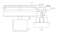
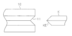
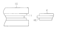
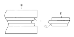
- the polishing apparatus includes a disk-shaped polishing member 10. Using the outer peripheral surface of the polishing member 10 in the radial direction, the end portion of the workpiece K to be polished is polished.
- the outer shape of the workpiece to be polished K that is, the projected shape of the surface orthogonal to the side surface to be polished in the workpiece to be polished K (the shape of the workpiece to be polished K shown in FIG. 1) is rectangular. More specifically, the corners of the rectangle are rounded rather than right. However, as other shapes, the corners of the quadrangle may be perpendicular.
- the shape of the end KE of the workpiece K (the shape of the portion to be polished) has been made into a curved shape by the previous processing, and the end KE processed into this curved shape is Polishing is performed by the polishing member 10.
- the material of the polishing member 10 can be arbitrarily selected from those optimal for polishing the end KE.
- any synthetic resin can be used. Examples thereof include a thermosetting resin (phenol resin, epoxy resin, urethane resin, polyimide, etc.) and a thermoplastic resin (polyethylene, polypropylene, acrylic resin, polyamide, polycarbonate, etc.). Further, it may be a woven fabric, a non-woven fabric, a non-woven fabric processed resin product, synthetic leather, or a composite product thereof.
- the hardness of the polishing surface of the polishing member 10 is preferably 5 or more in Shore A hardness.
- a Shore A hardness of 5 or more means that a polishing member 10 having a polished surface, which is a specimen whose hardness is to be measured, is placed in a dry state with a humidity of 20 to 60% at room temperature for 60 minutes or more, and is then placed in JIS K6253. It means that the hardness of the polished surface measured by a compliant rubber hardness meter (type A) is 5 or more.
- the Shore A hardness is 5 or more, the surface of the workpiece K can be suitably processed, and the polishing surface of the polishing member 10 can be prevented from being deformed by short-time polishing.
- the Shore A hardness of the polishing surface of the polishing member 10 is more preferably 40 or more, still more preferably 70 to 95, and particularly preferably 70 to 85. Further, when a metal is used as the material of the polishing member 10, magnesium, aluminum, titanium, iron, nickel, cobalt copper, zinc, manganese, or an alloy mainly composed thereof can be used as the material.
- polishing member 10 may have an abrasive grain.
- the type of abrasive grains used is not particularly limited, but metal oxide particles such as silicon oxide, aluminum oxide, zirconium oxide, cerium oxide, magnesium oxide, calcium oxide, titanium oxide, manganese oxide, iron oxide, and chromium oxide, and carbonized Carbides such as silicon, other nitrides, borides, diamonds and the like can be used.
- ceramics are used as the material of the polishing member 10, as materials, ceramics, glass, oxides such as silicon, aluminum, zirconium, calcium, barium, nitrides, borides, carbides, etc.
- oxides such as silicon, aluminum, zirconium, calcium, barium, nitrides, borides, carbides, etc.
- Aluminum, zirconium oxide, silicon oxide, silicon carbide, silicon nitride, boron nitride and the like can be used.
- any material can be used for the workpiece K to be polished.
- a resin any synthetic resin can be used.
- examples thereof include a thermosetting resin (phenol resin, epoxy resin, urethane resin, polyimide, etc.) and a thermoplastic resin (polyethylene, polypropylene, acrylic resin, polyamide, polycarbonate, etc.).
- ceramics When ceramics are used as the material of the workpiece K, ceramics, glass, fine ceramics, oxides such as silicon, aluminum, zirconium, calcium, barium, carbides, nitrides, borides, etc. Can be used.
- magnesium, aluminum, titanium, iron, nickel, cobalt, copper, zinc, manganese or an alloy containing the same as the main component can be used.
- the specific use of the workpiece K to be polished is also arbitrary.
- a wheel, a shaft, a container, a housing (a case, a housing, etc.), a frame (a frame, etc.), a ball, a wire, a decorative article, and the like can be used.
- the polishing member 10 is detachably fixed to the upper surface of the disk-shaped surface plate 20.
- a rotation shaft of the first motor 21 is fixed to the lower surface of the center portion of the surface plate 20.
- the first motor 21 is provided under the polishing member 10 and the surface plate 20, and the polishing member 10 disposed on the upper surface of the surface plate 20 is rotated together with the identification plate 20 from the bottom, so that the shaft shake and the like are stable. Since the rotation of the polishing member 10 can be obtained, more accurate processing can be performed.
- a polishing surface 11 having a groove-like curved surface extending in the circumferential direction is provided on the radially outer peripheral surface of the polishing member 10.
- the curved surface of the polishing surface 11 is formed along the shape of the end KE of the workpiece K to be polished. That is, the curvature of the polished surface 11 is the same as the curvature of the end KE.
- the diameter of the polishing member 10 is made as large as possible within a range where the polishing accuracy can be suitably maintained, the end portions KE of the plurality of workpieces K can be simultaneously polished on the outer peripheral surface of the polishing member 10. , Productivity can be improved. Further, if the diameter of the polishing member 10 is made as large as possible, even if the rotation speed of the polishing member 10 is the same, a large linear velocity can be obtained on the outer periphery. Even if it is relatively low, a sufficient linear velocity can be obtained. For this reason, for example, scattering of the machining liquid described later can be suppressed.
- the work piece K to be polished is detachably held on the fixed base 32.
- the fixed base 32 is fixed to the rotating shaft 31 of the second motor 30.
- the second motor 30 When the second motor 30 is driven, the workpiece K is rotated around the rotation shaft 31 (in the direction of arrow R or arrow L shown in FIG. 1).
- the second motor 30 constitutes the rotation mechanism.
- the second motor 30 is attached to the motor moving mechanism 33.
- the motor moving mechanism 33 includes a mechanism for reciprocating the second motor 30 in a direction orthogonal to the rotation axis of the polishing member 10.
- arrow X direction the direction orthogonal to the rotation axis of the polishing member 10 is referred to as “arrow X direction” (shown in FIG. 2).
- the motor moving mechanism 33 also includes a mechanism for reciprocating the second motor 30 in the tangential direction on the outer circumferential surface of the polishing member 10 in the radial direction.
- arrow Y direction shown in FIG. 1.
- the second motor 30 When the second motor 30 is moved by the motor moving mechanism 33, the second motor 30, the rotating shaft 31, the fixed base 32, and the workpiece K to be polished are integrated in a direction orthogonal to the rotating shaft of the polishing member 10.
- the polishing member 10 moves in the tangential direction on the outer circumferential surface in the radial direction.
- the motor moving mechanism 33 constitutes the first moving mechanism and the second moving mechanism.
- the polishing apparatus further includes a pressing mechanism 40 that presses the workpiece K in a direction orthogonal to the rotation axis of the polishing member 10.
- the pressing mechanism 40 presses the workpiece K with the pressure P against the polishing surface 11 of the polishing member 10.
- Such adjustment of the pressure P by the pressing mechanism 40 can be arbitrarily performed.
- the contact pressure at the contact portion between the end KE of the workpiece K and the polishing surface 11 is measured with a load cell or the like.
- the pressure P is adjusted so that the contact pressure becomes constant at a specified value.
- the pressure P may be adjusted according to the area of the contact portion (for example, the pressure P is increased at a site where the area of the contact portion is large, and the pressure P is decreased at a site where the area of the contact portion is small).
- the contact pressure tends to be higher at the corners than at the flat part. Therefore, the polishing time of a portion of the workpiece K where the contact pressure increases such as a corner is shortened, and the polishing time of the portion of the workpiece K where the contact pressure increases such as a flat portion is long.
- appropriate polishing control may be performed according to the shape of the workpiece K to be polished, or the processing time may be adjusted together with the adjustment of the pressure P so that constant polishing is performed.
- an appropriate power source such as electric power, hydraulic pressure, air pressure, gas pressure, or the like can be used.
- the motor moving mechanism 33 and the pressing mechanism 40 are driven by an automatic drive by a control device including a CPU, a RAM, a ROM, and the like, a switch operation of an operator who operates the polishing apparatus, and the like.
- the end KE of the workpiece K is pressed against the polishing surface 11 by the movement of the second motor 30 by the motor moving mechanism 33 and the pressing of the workpiece K by the pressing mechanism 40. Then, the processing liquid or the like is supplied to the contact portion between the end KE and the polishing surface 11 in an appropriate manner.
- Such machining fluid can be supplied directly from the outside to the contact portion between the end KE and the polishing surface 11.
- a machining fluid supply mechanism such as a rotary joint is interposed between the polishing member 10 (more specifically, the surface plate 20 on which the polishing member 10 is fixed) and the first motor 21.
- the machining liquid is supplied from the machining liquid supply mechanism to the inside of the polishing member 10, and the machining liquid supplied to the inside of the polishing member 10 is supplied to the contact portion through a supply path formed inside the polishing member 10. It can also be supplied.
- the processing liquid can be supplied more efficiently.
- the above-described types of processing fluid can be used in accordance with the material to be polished K and the polishing member 10. Specifically, cutting and grinding working fluids, lapping materials, polishing agents, chemical mechanical polishing polishing fluids, and the like can be used.
- the processing liquid may contain abrasive grains.
- the type of abrasive grains used is not particularly limited, but metal oxide particles such as silicon oxide, aluminum oxide, zirconium oxide, cerium oxide, magnesium oxide, calcium oxide, titanium oxide, manganese oxide, iron oxide, and chromium oxide, and carbonized Carbides such as silicon, nitrides, borides, diamonds and the like can be used.
- the content of abrasive grains in the working fluid is preferably 1% by mass or more, more preferably 2% by mass or more.
- content of the abrasive grain in a processing liquid is 50 mass% or less, More preferably, it is 40 mass% or less.
- the average secondary particle diameter of the abrasive grains in the working fluid is preferably 0.1 ⁇ m or more, more preferably 0.3 ⁇ m or more. As the average secondary particle diameter of the abrasive grains increases, the processing speed by the processing liquid is improved.
- the average secondary particle diameter of the abrasive grains in the working fluid is preferably 20 ⁇ m or less, more preferably 5 ⁇ m or less.
- the average secondary particle diameter of the abrasive grains in the processing liquid decreases, the surface of the workpiece K can be more uniformly polished.
- the average secondary particle diameter of abrasive grains is, for example, the volume average particle diameter measured using a laser diffraction / scattering particle size distribution measuring device such as “LA-950” manufactured by Horiba Ltd. is there.
- a pH adjuster In the above-mentioned processing liquid, a pH adjuster, an etching agent, an oxidizing agent, a water-soluble polymer, a copolymer and a salt thereof, a derivative, an anticorrosive agent, a chelating agent, a dispersion aid, an antiseptic agent, and an antifungal agent, as necessary It may further contain other components such as an agent.
- pH adjuster known acids, bases, or salts thereof can be used.
- acids that can be used as pH adjusters include inorganic acids such as hydrochloric acid, sulfuric acid, nitric acid, hydrofluoric acid, boric acid, carbonic acid, hypophosphorous acid, phosphorous acid, and phosphoric acid, formic acid, acetic acid, Propionic acid, butyric acid, valeric acid, 2-methylbutyric acid, n-hexanoic acid, 3,3-dimethylbutyric acid, 2-ethylbutyric acid, 4-methylpentanoic acid, n-heptanoic acid, 2-methylhexanoic acid, n-octane Acid, 2-ethylhexanoic acid, benzoic acid, glycolic acid, salicylic acid, glyceric acid, oxalic acid, malonic acid, succinic acid, glutaric acid, adipic acid, pimelic acid, maleic acid,
- a salt such as an ammonium salt or an alkali metal salt of the above-mentioned acid may be used as a pH adjuster.
- a pH adjuster is used to adjust the pH value of the processing liquid to an optimum value that varies depending on the type of workpiece K to be polished.
- etching agent examples include inorganic acids such as nitric acid, sulfuric acid and phosphoric acid, acetic acid, citric acid, organic acids such as tartaric acid and methanesulfonic acid, inorganic alkalis such as potassium hydroxide and sodium hydroxide, ammonia, amines, And organic alkalis such as quaternary ammonium hydroxides.
- oxidizing agent examples include hydrogen peroxide, peracetic acid, percarbonate, urea peroxide, perchlorate, persulfate and the like, oxo acids such as sulfuric acid, nitric acid, phosphoric acid and salts thereof, and the like. Examples include salts.
- water-soluble polymers, copolymers, salts and derivatives thereof examples include polycarboxylic acids such as polyacrylates, polysulfonic acids such as polyphosphonic acid and polystyrene sulfonic acid, polysaccharides such as chitansan gum and sodium alginate, hydroxy Cellulose derivatives such as ethyl cellulose and carboxymethyl cellulose, polyethylene glycol, polyvinyl alcohol, polyvinyl pyrrolidone, sorbitan monooleate, oxyalkylene polymers having one or more oxyalkylene units, nonionic surfactants, anionic surfactants Agents and the like.
- polycarboxylic acids such as polyacrylates
- polysulfonic acids such as polyphosphonic acid and polystyrene sulfonic acid
- polysaccharides such as chitansan gum and sodium alginate
- hydroxy Cellulose derivatives such as ethyl cellulose and carboxymethyl cellulose
- nonionic surfactants include polyoxyethylene alkyl ether, polyoxyethylene alkyl phenyl ether, sorbitan monooleate, oxyalkylene polymers having a single kind or plural kinds of oxyalkylene units.
- anionic surfactants include alkyl sulfonic acid compounds, alkyl benzene sulfonic acid compounds, alkyl naphthalene sulfonic acid compounds, methyl tauric acid compounds, alkyl diphenyl ether disulfonic acid compounds, ⁇ -olefin sulfonic acid compounds, Naphthalenesulfonic acid condensate, sulfosuccinic acid diester compound and the like.
- anticorrosives examples include amines, pyridines, tetraphenylphosphonium salts, benzotriazoles, triazoles, tetrazoles, benzoic acid, monocyclic compounds, polycyclic compounds having a condensed ring, heterocyclic compounds, etc. Is mentioned.
- the chelating agents include carboxylic acid chelating agents such as gluconic acid, amine chelating agents such as ethylenediamine, diethylenetriamine, and trimethyltetraamine, ethylenediaminetetraacetic acid, nitrilotriacetic acid, hydroxyethylethylenediaminetriacetic acid, triethylenetetramine hexa Polyaminopolycarboxylic chelating agents such as acetic acid and diethylenetriaminepentaacetic acid, 2-aminoethylphosphonic acid, 1-hydroxyethylidene-1,1-diphosphonic acid, aminotri (methylenephosphonic acid), ethylenediaminetetrakis (methylenephosphonic acid), diethylenetriaminepenta (Methylenephosphonic acid), ethane-1,1-diphosphonic acid, ethane-1,1,2-triphosphonic acid, methanehydroxyphosphonic acid, 1-phosphonobutane-2,3 - organic phosphonic acid chel
- dispersion aid examples include condensed phosphates such as pyrophosphate and hexametaphosphate.
- preservative include sodium hypochlorite and the like.
- the antifungal agent examples include oxazolines such as oxazolidine-2,5-dione. Then, the rotation speed of the first motor 21 is adjusted along with the above-described supply of the processing fluid and the like, so that the curved end KE is polished. The polishing of the end KE can be performed, for example, in the following process order.
- Process 1 The workpiece KE is moved toward the center of rotation of the polishing member 10 in the arrow X direction by the motor moving mechanism 33 to bring the end KE into contact with the polishing surface 11.
- Step 2 Next, the workpiece KE is moved in the arrow Y direction by the motor moving mechanism 33 while the pressing mechanism 40 is driven in a state where the end KE and the polishing surface 11 are in contact with each other, thereby the end KE. And the contact part with the polishing surface 11 are changed. As a result, the polishing of one side of the workpiece K progresses.
- Step 3 When the polishing of one side of the workpiece K is finished, the pressing mechanism 40 is separated from the end KE. Then, the workpiece K is rotated by the second motor 30 while the workpiece K is moved in the arrow X direction by the motor moving mechanism 33. By rotating the workpiece K while maintaining the state where the workpiece K and the polishing surface 11 are in contact with each other, the side adjacent to the side where the polishing is finished is directed toward the polishing surface 11, and polishing is performed. The edge to be switched is switched.
- step 2 and step 3 all four sides of the workpiece K are polished.
- the above-described polishing process is an example, and the driving mode of the motor moving mechanism 33 and the pressing mechanism 40 can be changed as appropriate in consideration of the processing time and the like.
- the workpiece K is moved by the motor moving mechanism 33 in the tangential direction (arrow Y direction) on the radially outer peripheral surface of the polishing member 10. Therefore, the workpiece K and the polishing member 10 are relatively moved linearly. Therefore, the end portion KE of the quadrilateral workpiece K having linear sides can be polished.
- the polishing apparatus includes a polishing member 10 having a polishing surface 11 having a shape along the shape of the end KE of the workpiece K to be polished. Therefore, even if the end KE of the workpiece K is a curved surface shape different from the planar shape, the end KE can be polished.
- the workpiece K is polished using a polishing apparatus. Therefore, even if the shape of the portion to be polished (the shape of the end KE) has a curved shape different from the flat shape, and the rectangular workpiece K is polished, the outer periphery thereof can be polished.
- the said embodiment can also be changed and implemented as follows.
- the entire outer periphery of the workpiece K is polished by rotating the workpiece K, but instead, a part of the outer periphery of the workpiece K, for example, the workpiece K Only one side, only two sides, or only three sides may be polished.
- the workpiece K is rotated while moving in the direction of the arrow X away from the center of rotation of the polishing member 10, but instead, the end KE that has been polished is
- the workpiece K may be rotated.
- the workpiece K may be moved in the arrow Y direction so that the next side to be polished in the workpiece K approaches the polishing surface 11. Even if the sides to be polished are changed in this way, each side of the workpiece K can be polished.
- the function of the motor moving mechanism 33 that moves the workpiece K in the arrow X direction can be omitted.
- the motor moving mechanism 33 has only a function of moving the workpiece K in the arrow Y direction,
- the rotation mechanism (second motor 30 or the like) may be omitted. Even in this case, the workpiece K and the polishing member 10 are linearly moved relative to each other by the motor moving mechanism 33, and therefore, the end portion KE of the rectangular workpiece K having a linear side. One side can be polished.
- the workpiece K can be moved in the direction of the arrow X and the direction of the arrow Y, but in addition, a mechanism for moving the rotation center of the polishing member 10 may be provided. Then, the workpiece K may be moved in the arrow X direction and the polishing member 10 may be moved in the arrow Y direction. Alternatively, the workpiece K may be moved in the arrow Y direction, and the polishing member 10 may be moved in the arrow X direction.
- both the workpiece K and the polishing member 10 may be moved in the arrow X direction, or both the workpiece K and the polishing member 10 may be moved in the arrow Y direction.
- the workpiece K is movable, but instead, the polishing member 10 may be configured to be movable.
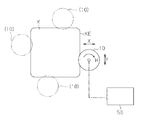
- FIG. 3 shows an outline of such a modification.
- a moving mechanism 50 for moving the polishing member 10 is provided at the rotational center of the polishing member 10 that is rotationally driven.
- the moving mechanism 50 has a function as a first moving mechanism for moving the polishing member 10 in a tangential direction (in the direction of arrow Y shown in FIG. 3) on the radially outer peripheral surface of the polishing member 10, and a rotating shaft of the polishing member 10. It also has a function as a second moving mechanism for moving the polishing member 10 in a direction orthogonal to the direction (the direction of the arrow X shown in FIG. 3).
- an appropriate mechanism can be adopted.
- a link mechanism or a mechanism similar to the motor moving mechanism 33 can be employed.
- the position of the polishing member 10 with respect to the workpiece K can be arbitrarily changed by the moving mechanism 50, so that the workpiece is polished while following the outer shape of the workpiece K to be polished.
- the contact state between the workpiece K and the polishing member 10 can be maintained. That is, as shown by a two-dot chain line in FIG. 3, the polishing member 10 can be moved along the outer periphery (end portion KE) of the workpiece K to be polished. Therefore, even in such a modification, the entire outer periphery of the workpiece K having a quadrangular outer shape can be polished.
- the entire outer periphery of the workpiece K can be polished even if the size of the polishing member 10 is relatively small compared to the above embodiment.
- a moving mechanism that moves the polishing member 10 in the direction of arrow Y shown in FIG. 3 and a moving mechanism that moves the polishing member 10 in the direction of arrow X shown in FIG. May be provided separately.
- a part of the outer periphery of the workpiece K for example, only one side of the workpiece K, only two sides, or only three sides may be polished. Good.
- the polishing member 10 is provided on the upper surface of the surface plate 20, the surface plate 20 may be omitted and the rotation shaft of the first motor 21 may be directly fixed to the center of the polishing member 10.
- the end KE is pressed against the polishing surface 11 by driving the pressing mechanism 40, the end KE is moved to the polishing surface 11 by moving the second motor 30 in the arrow X direction by the motor moving mechanism 33. If it can be pressed, the pressing mechanism 40 may be omitted.
- the second motor 30 is tangent to the outer circumferential surface in the direction perpendicular to the rotation axis of the polishing member 10 (the direction of the arrow X shown in FIG. 2) and the radial direction of the polishing member 10. However, instead, the second motor 30 is moved in a direction perpendicular to the rotation axis of the polishing member 10 (shown in FIG. 2 above). And a mechanism for moving the second motor 30 in the tangential direction on the radial outer peripheral surface of the polishing member 10 (in the direction of arrow Y shown in FIG. 1 above). It may be.
- the workpiece K may be moved in another manner.
- the edge part KE of the workpiece K was grind
- the shape of the end KE of the workpiece K may be a non-planar shape other than a curved surface, for example, a triangular shape as shown in FIG. 5 or a substantially triangular shape as shown in FIG. The shape may have a tinge. Further, the shape of the end KE of the workpiece K may be a stepped shape shown in FIG. 7 or a substantially stepped shape as shown in FIG. 8 with rounded corners. Further, as shown in FIG. 9, the end KE may have a curved shape that is recessed toward the inner side of the workpiece K. Further, it may be a curved surface composed of a plurality of curvatures or a curved surface partially including a straight line portion. Also in these modifications, the end KE is polished by making the polishing surface 11 of the polishing member 10 along the shape of the end KE of the workpiece K (the shape of the part to be polished). Can do.
- the outer shape of the workpiece K may be any other shape other than a square shape.
- the shape which consists of a some plane and a curved surface may be sufficient, and triangular shape and elliptical shape may be sufficient.
- the workpiece K having various outer shapes can be polished, for example, the peripheral surface of a cylindrical workpiece K having a circular outer shape is polished. It is also possible to do.
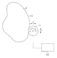
- the position of the polishing member 10 with respect to the workpiece K can be arbitrarily changed. Therefore, as shown in FIG. Even if it is a shape formed with the curvature of, the outer periphery can be polished.
- the workpiece K to be polished in order to make the end KE of the workpiece K to be in contact with the polishing surface 11 or to separate the end KE after the polishing from the polishing surface 11, the workpiece K to be polished is used.
- the workpiece to be polished K can be moved in the direction of the arrow X and the direction of the arrow Y, so that the position of the workpiece to be polished K with respect to the polishing member 10 can be arbitrarily changed. Is possible. Therefore, the contact state between the workpiece K and the polishing member 10 can be maintained while following the outer shape of the workpiece K.
- the polishing apparatus of the above embodiment also includes a rotation mechanism that rotates the workpiece K to be polished. Therefore, also in the above-mentioned embodiment, the shape as shown in FIG. 4 is obtained by combining the movement of the workpiece K in the direction of the arrow X and the direction of the arrow Y and the rotation of the workpiece K to be polished. Even if the workpiece K, that is, the outer shape of the workpiece K is formed with a plurality of curvatures, the outer periphery thereof can be polished.
- a feature (A) if at least one of the workpiece K or the polishing member 10 is moved in the tangential direction (arrow Y direction) on the radial outer peripheral surface of the polishing member 10, the workpiece to be polished One side of the object K can be polished. Further, as the feature (B), at least one of the workpiece K or the polishing member 10 is moved in a direction (arrow X direction) orthogonal to the rotation axis of the polishing member 10, and the workpiece K Alternatively, if at least one of the polishing members 10 is moved in a tangential direction (arrow Y direction) on the outer circumferential surface of the polishing member 10 in the radial direction, the positional relationship between the workpiece K and the polishing member 10 is arbitrary.
- the polishing treatment of the workpiece is performed. While being able to promote, it can accelerate
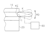
- a reciprocating mechanism that reciprocates at least one of the polishing member 10 and the workpiece K to be polished in a direction crossing the rotation direction is further provided. You may do it. Two examples when such a reciprocating mechanism is provided in the polishing apparatus of the above-described embodiment shown in FIG. 2 and the like are shown in FIGS.
- the 10 includes a rocking mechanism 60 that rocks the workpiece K in a direction perpendicular to the rotation direction of the polishing member 10.
- a rocking mechanism 60 that rocks the workpiece K in a direction perpendicular to the rotation direction of the polishing member 10.
- an appropriate mechanism such as a link mechanism can be employed.
- the swing mechanism 60 when the polishing member 10 is rotated to polish the end KE of the workpiece K, the swing mechanism 60 is operated. By the operation of the swing mechanism 60, the workpiece K is swung in a direction orthogonal to the rotation direction of the polishing member 10 (the direction of the arrow RO shown in FIG. 10). Then, due to the swinging motion of the workpiece K, the end portion KE of the workpiece K during the rotational polishing swings along the curved surface of the polishing surface 11. Due to the swinging of the end KE, the polishing mark at the end KE becomes crossed, and the polishing mark becomes smaller than that of the rotation-only polishing. Accordingly, it is possible to suppress polishing marks caused by rotational polishing.
- the swinging direction of the workpiece K with respect to the rotation direction of the polishing member 10 is not necessarily limited to the orthogonal direction, and the swinging direction is at least crossed with respect to the rotation direction of the polishing member 10. In this case, since the polishing marks are crossed, the polishing marks due to rotational polishing can be suppressed. Further, the polishing member 10 may be rocked instead of the workpiece K to be polished. Further, both the workpiece K and the polishing member 10 may be swung.
- vibration mechanism 70 that vibrates the workpiece K in a small direction in a direction orthogonal to the rotation direction of the polishing member 10.
- the vibration mechanism 70 an appropriate mechanism such as a mechanism using ultrasonic vibration can be employed.
- the vibration mechanism 70 when the polishing member 10 is rotated to polish the end KE of the workpiece K, the vibration mechanism 70 is operated.
- the workpiece K is vibrated slightly in a direction orthogonal to the rotation direction of the polishing member 10 (the direction of the arrow UD shown in FIG. 11).
- the end KE of the workpiece to be polished K that is being rotationally polished reciprocally moves in the direction of the arrow UD while being in contact with the curved surface of the polishing surface 11.
- the polishing mark of the end KE becomes crossed, and the polishing mark is smaller than that of the rotation-only polishing. Therefore, even in this modified example, it becomes possible to suppress polishing marks caused by rotational polishing.
- the vibration direction of the workpiece K with respect to the rotation direction of the polishing member 10 is not necessarily limited to the orthogonal direction, and if the vibration is performed in a direction at least crossing the rotation direction of the polishing member 10, Since the polishing marks are crossed, polishing marks due to rotational polishing can be suppressed. Further, the polishing member 10 instead of the workpiece K may be vibrated. Further, both the workpiece K and the polishing member 10 may be vibrated.
- the above-described reciprocating mechanism can be similarly applied to a polishing apparatus (for example, the polishing apparatus shown in FIG. 3 or the like) in the modified example of the above-described embodiment. Can be suppressed.
- the workpiece K to be polished with respect to the polishing surface 11 is perpendicular to the rotation axis of the polishing member 10 (the direction of the arrow X shown in FIG. 2 and the like). ),
- the end portion KE of the workpiece K to be polished was polished.
- the end KE thus pressed can be polished, but the upper and lower surfaces of the workpiece K, that is, the object to be polished which is parallel to the plane in which the rotation axis of the polishing member 10 is orthogonal. Since both sides of the workpiece K do not require excessive pressure during polishing, there is a possibility that sufficient polishing cannot be performed. Therefore, in addition to the various mechanisms described above, a pressure applying mechanism that applies a pressure perpendicular to both surfaces of the workpiece K may be further provided.
- FIG. 12 shows a schematic configuration of an example of such a pressure applying mechanism.
- the pressure applying mechanism includes a roller 80, an actuator 82, and the like.
- the roller 80 is disk-shaped and rotates around the rotation shaft 81. Further, the outer peripheral surface of the roller 80 is in contact with the vicinity of the outer periphery of the upper surface 10U of the polishing member 10, and the roller 80 also rotates as the upper surface 10U rotates.
- the roller 80 and the upper surface 10U only need to be in contact at least during polishing of the workpiece K to be polished. Accordingly, the roller 80 and the upper surface 10U may always be in contact with each other, or may be in contact only during polishing of the workpiece K to be polished.
- the actuator 82 is a mechanism that presses the roller 80 against the upper surface 10U, and is configured by an appropriate mechanism such as an electric type or a hydraulic type. During polishing of the workpiece K, the roller 80 is pressed against the upper surface 10U by the operation of the actuator 82 (in the direction of arrow VT shown in FIG. 12).
- the pressing force F that presses the polishing surface 11 of the polishing member 10 is applied to the upper surface KU of the workpiece K to be polished. Further, when the pressing force F is applied to the upper surface KU in this way, the lower surface KD of the workpiece K is pressed against the polishing surface 11 of the polishing member 10 with which the lower surface KD contacts, and as a result, A pressing force F similar to that of the upper surface KU of the workpiece K is also applied to the lower surface KD of the polished workpiece K.
- the upper surface KU and the lower surface KD can be polished simultaneously with the end KE when the workpiece K is polished.
- a pressing force F is applied to the upper surface KU and the lower surface KD of the workpiece K by pressing one surface (upper surface U) of the polishing member 10 with a pressure applying mechanism. The Therefore, the number of pressure applying mechanisms can be reduced as compared with the case where pressure applying mechanisms are provided on both surfaces of the polishing member 10.
- the roller 80 is pressed by the actuator 82, but the mass of the roller 80 is sufficiently large, and a sufficient pressing force F can be applied only by its own weight. If present, the actuator 82 may be omitted.
- one surface of the polishing member 10 is pressed. However, both surfaces may be pressed by sandwiching both surfaces of the polishing member 10, for example. When both sides are pressed in this manner, for example, distortion of the polishing member 10 can be suppressed as compared with the case where one side is pressed.
- the roller 80 does not need to be configured to be rotatable. In this case, for example, the roller 80 is simply weighted or the like. It is also possible to change to.
Abstract
Priority Applications (5)
| Application Number | Priority Date | Filing Date | Title |
|---|---|---|---|
| EP14851309.6A EP3053703A4 (fr) | 2013-10-04 | 2014-10-02 | Dispositif de polissage et procédé de polissage |
| US15/026,089 US20160236314A1 (en) | 2013-10-04 | 2014-10-02 | Polishing device and polishing method |
| JP2015540534A JPWO2015050186A1 (ja) | 2013-10-04 | 2014-10-02 | 研磨装置及び研磨方法 |
| CN201480054424.4A CN105658377A (zh) | 2013-10-04 | 2014-10-02 | 研磨装置以及研磨方法 |
| KR1020167008523A KR20160067106A (ko) | 2013-10-04 | 2014-10-02 | 연마 장치 및 연마 방법 |
Applications Claiming Priority (2)
| Application Number | Priority Date | Filing Date | Title |
|---|---|---|---|
| JP2013-209602 | 2013-10-04 | ||
| JP2013209602 | 2013-10-04 |
Publications (1)
| Publication Number | Publication Date |
|---|---|
| WO2015050186A1 true WO2015050186A1 (fr) | 2015-04-09 |
Family
ID=52778773
Family Applications (1)
| Application Number | Title | Priority Date | Filing Date |
|---|---|---|---|
| PCT/JP2014/076360 WO2015050186A1 (fr) | 2013-10-04 | 2014-10-02 | Dispositif de polissage et procédé de polissage |
Country Status (7)
| Country | Link |
|---|---|
| US (1) | US20160236314A1 (fr) |
| EP (1) | EP3053703A4 (fr) |
| JP (2) | JPWO2015050186A1 (fr) |
| KR (1) | KR20160067106A (fr) |
| CN (1) | CN105658377A (fr) |
| TW (1) | TW201529224A (fr) |
| WO (1) | WO2015050186A1 (fr) |
Cited By (2)
| Publication number | Priority date | Publication date | Assignee | Title |
|---|---|---|---|---|
| JP2015174180A (ja) * | 2014-03-14 | 2015-10-05 | 株式会社東京精密 | 超音波面取り機 |
| JP2016043692A (ja) * | 2014-08-19 | 2016-04-04 | 信越化学工業株式会社 | インプリント・リソグラフィ用角形基板及びその製造方法 |
Families Citing this family (4)
| Publication number | Priority date | Publication date | Assignee | Title |
|---|---|---|---|---|
| JP6568006B2 (ja) * | 2016-04-08 | 2019-08-28 | 株式会社荏原製作所 | 研磨装置および研磨方法 |
| CN108436650A (zh) * | 2018-03-08 | 2018-08-24 | 北京铂阳顶荣光伏科技有限公司 | 磨边方法及装置 |
| US11799150B2 (en) | 2020-07-17 | 2023-10-24 | Toyota Motor Engineering & Manufacturing North America, Inc. | Cooling structure for hybrid-electric vehicle battery cell assemblies |
| CN115365928A (zh) * | 2022-08-23 | 2022-11-22 | 北京航空航天大学宁波创新研究院 | 一种研磨方法及研磨机 |
Citations (10)
| Publication number | Priority date | Publication date | Assignee | Title |
|---|---|---|---|---|
| JPS5388291A (en) * | 1977-01-12 | 1978-08-03 | Fukuyama Tetsukoushiyo Kk | Machine for automatically pol shuing all circumference of plate glass |
| JPS591548U (ja) * | 1982-06-29 | 1984-01-07 | 小出 ▲けん▼ | 倣い研磨用砥石装置 |
| JPS60143646U (ja) * | 1984-03-02 | 1985-09-24 | 豊田工機株式会社 | 研削装置 |
| JPS6165763A (ja) * | 1984-09-06 | 1986-04-04 | Nippon Sheet Glass Co Ltd | 板状体の端面研磨装置 |
| JPH01170558U (fr) * | 1988-05-24 | 1989-12-01 | ||
| JPH04360772A (ja) * | 1991-06-05 | 1992-12-14 | Toto Ltd | 平板面取用砥石及び平板面取装置 |
| JPH1170471A (ja) * | 1997-07-03 | 1999-03-16 | Asahi Glass Co Ltd | ガラス面取り方法およびその装置 |
| JPH11188590A (ja) | 1997-12-22 | 1999-07-13 | Speedfam Co Ltd | エッジポリッシング装置 |
| JP2001038589A (ja) * | 1999-08-03 | 2001-02-13 | Speedfam Co Ltd | ワーク外周部用研磨装置 |
| JP2001205549A (ja) | 2000-01-25 | 2001-07-31 | Speedfam Co Ltd | 基板エッジ部の片面研磨方法およびその装置 |
Family Cites Families (29)
| Publication number | Priority date | Publication date | Assignee | Title |
|---|---|---|---|---|
| GB1082418A (en) * | 1966-07-22 | 1967-09-06 | Toolmasters Ltd | Improvements relating to grinding wheels |
| JPS5250088A (en) * | 1975-10-15 | 1977-04-21 | Monsanto Co | Crush forming roll |
| JPS6165762A (ja) * | 1984-09-06 | 1986-04-04 | Nippon Sheet Glass Co Ltd | 板状体の端面研磨装置 |
| US5083401A (en) * | 1988-08-08 | 1992-01-28 | Mitsubishi Denki Kabushiki Kaisha | Method of polishing |
| JP2559650B2 (ja) * | 1991-11-27 | 1996-12-04 | 信越半導体株式会社 | ウエーハ面取部研磨装置 |
| KR100277320B1 (ko) * | 1992-06-03 | 2001-01-15 | 가나이 쓰도무 | 온라인 롤 연삭 장치를 구비한 압연기와 압연 방법 및 회전 숫돌 |
| JP3010572B2 (ja) * | 1994-09-29 | 2000-02-21 | 株式会社東京精密 | ウェーハエッジの加工装置 |
| JP2000176805A (ja) * | 1998-12-17 | 2000-06-27 | Mitsubishi Materials Silicon Corp | 半導体ウェーハの面取り装置 |
| DE19914174A1 (de) * | 1999-03-29 | 2000-10-12 | Wernicke & Co Gmbh | Verfahren und Vorrichtung zum Formbearbeiten des Umfangsrandes von Brillengläsern |
| JP2001062686A (ja) * | 1999-08-25 | 2001-03-13 | Speedfam Co Ltd | インデックス式エッジポリッシャー |
| JPWO2002005337A1 (ja) * | 2000-07-10 | 2004-01-08 | 信越半導体株式会社 | 鏡面面取りウェーハ、鏡面面取り用研磨クロス、及び鏡面面取り研磨装置及び方法 |
| TWI352645B (en) * | 2004-05-28 | 2011-11-21 | Ebara Corp | Apparatus for inspecting and polishing substrate r |
| JP2007088143A (ja) * | 2005-09-21 | 2007-04-05 | Elpida Memory Inc | エッジ研磨装置 |
| ES2279719B1 (es) * | 2006-01-26 | 2008-07-16 | Timac Agro España, S.A. | Nuevo activador metabolico y nutricional para las plantas. |
| CN101284365A (zh) * | 2007-04-13 | 2008-10-15 | 奇美电子股份有限公司 | 基板的旋转装置、磨边装置及磨边方法 |
| US20080293329A1 (en) * | 2007-05-21 | 2008-11-27 | Applied Materials, Inc. | Methods and apparatus for identifying a substrate edge profile and adjusting the processing of the substrate according to the identified edge profile |
| WO2009116945A1 (fr) * | 2008-03-20 | 2009-09-24 | Telefonaktiebolaget Lm Ericsson (Publ) | Procédé et appareil de communication de paquets entre des réseau locaux |
| US8585467B2 (en) * | 2008-10-31 | 2013-11-19 | Corning Incorporated | Linear pressure feed grinding with voice coil |
| JP2010182813A (ja) * | 2009-02-04 | 2010-08-19 | Noritake Super Abrasive Co Ltd | Cmpパッドコンディショナー |
| CN201380419Y (zh) * | 2009-03-02 | 2010-01-13 | 湖北新火炬科技股份有限公司 | 金刚滚轮磨削砂轮用于磨削轮毂总成内滚道的装置 |
| JP5352331B2 (ja) * | 2009-04-15 | 2013-11-27 | ダイトエレクトロン株式会社 | ウェーハの面取り加工方法 |
| CN102427913B (zh) * | 2009-05-15 | 2014-01-15 | 旭硝子株式会社 | 玻璃端面磨削用磨具的加工位置设定方法 |
| CN101612717A (zh) * | 2009-07-17 | 2009-12-30 | 李留江 | 数控球轴承内圈沟道多功能磨床 |
| US8892238B2 (en) * | 2009-10-06 | 2014-11-18 | Edward T. Sweet | Edge break details and processing |
| JP5519256B2 (ja) * | 2009-12-03 | 2014-06-11 | 株式会社荏原製作所 | 裏面が研削された基板を研磨する方法および装置 |
| US8747188B2 (en) * | 2011-02-24 | 2014-06-10 | Apple Inc. | Smart automation of robotic surface finishing |
| US8986072B2 (en) * | 2011-05-26 | 2015-03-24 | Corning Incorporated | Methods of finishing an edge of a glass sheet |
| EP2537634A1 (fr) * | 2011-06-21 | 2012-12-26 | WENDT GmbH | Procédé de ponçage de la surface d'angle circonférentielle d'une vitrification |
| JP5898984B2 (ja) * | 2012-02-03 | 2016-04-06 | 中村留精密工業株式会社 | 硬質脆性板の側辺加工装置 |
-
2014
- 2014-10-02 JP JP2015540534A patent/JPWO2015050186A1/ja active Pending
- 2014-10-02 US US15/026,089 patent/US20160236314A1/en not_active Abandoned
- 2014-10-02 KR KR1020167008523A patent/KR20160067106A/ko not_active Application Discontinuation
- 2014-10-02 CN CN201480054424.4A patent/CN105658377A/zh active Pending
- 2014-10-02 WO PCT/JP2014/076360 patent/WO2015050186A1/fr active Application Filing
- 2014-10-02 EP EP14851309.6A patent/EP3053703A4/fr not_active Withdrawn
- 2014-10-02 TW TW103134429A patent/TW201529224A/zh unknown
-
2017
- 2017-10-06 JP JP2017196150A patent/JP2018001406A/ja active Pending
Patent Citations (10)
| Publication number | Priority date | Publication date | Assignee | Title |
|---|---|---|---|---|
| JPS5388291A (en) * | 1977-01-12 | 1978-08-03 | Fukuyama Tetsukoushiyo Kk | Machine for automatically pol shuing all circumference of plate glass |
| JPS591548U (ja) * | 1982-06-29 | 1984-01-07 | 小出 ▲けん▼ | 倣い研磨用砥石装置 |
| JPS60143646U (ja) * | 1984-03-02 | 1985-09-24 | 豊田工機株式会社 | 研削装置 |
| JPS6165763A (ja) * | 1984-09-06 | 1986-04-04 | Nippon Sheet Glass Co Ltd | 板状体の端面研磨装置 |
| JPH01170558U (fr) * | 1988-05-24 | 1989-12-01 | ||
| JPH04360772A (ja) * | 1991-06-05 | 1992-12-14 | Toto Ltd | 平板面取用砥石及び平板面取装置 |
| JPH1170471A (ja) * | 1997-07-03 | 1999-03-16 | Asahi Glass Co Ltd | ガラス面取り方法およびその装置 |
| JPH11188590A (ja) | 1997-12-22 | 1999-07-13 | Speedfam Co Ltd | エッジポリッシング装置 |
| JP2001038589A (ja) * | 1999-08-03 | 2001-02-13 | Speedfam Co Ltd | ワーク外周部用研磨装置 |
| JP2001205549A (ja) | 2000-01-25 | 2001-07-31 | Speedfam Co Ltd | 基板エッジ部の片面研磨方法およびその装置 |
Non-Patent Citations (1)
| Title |
|---|
| See also references of EP3053703A4 * |
Cited By (2)
| Publication number | Priority date | Publication date | Assignee | Title |
|---|---|---|---|---|
| JP2015174180A (ja) * | 2014-03-14 | 2015-10-05 | 株式会社東京精密 | 超音波面取り機 |
| JP2016043692A (ja) * | 2014-08-19 | 2016-04-04 | 信越化学工業株式会社 | インプリント・リソグラフィ用角形基板及びその製造方法 |
Also Published As
| Publication number | Publication date |
|---|---|
| JP2018001406A (ja) | 2018-01-11 |
| CN105658377A (zh) | 2016-06-08 |
| EP3053703A4 (fr) | 2017-07-26 |
| EP3053703A1 (fr) | 2016-08-10 |
| JPWO2015050186A1 (ja) | 2017-03-09 |
| US20160236314A1 (en) | 2016-08-18 |
| KR20160067106A (ko) | 2016-06-13 |
| TW201529224A (zh) | 2015-08-01 |
Similar Documents
| Publication | Publication Date | Title |
|---|---|---|
| JP2018001406A (ja) | 研磨装置及び研磨方法 | |
| JP2013082021A (ja) | 切削装置 | |
| WO2015020082A1 (fr) | Outil de polissage et procédé de traitement pour élément | |
| CN101740442A (zh) | 薄板状工件的搬送装置 | |
| JP6474861B2 (ja) | 研磨装置、研磨部材の加工又は修正用工具、研磨部材の加工又は修正方法、及び研磨部材の製造方法 | |
| JP2009095952A (ja) | ウェハの製造方法 | |
| JP2015196224A (ja) | 研磨方法、及び保持具 | |
| KR20190116923A (ko) | SiC 기판의 연마 방법 | |
| JP5470081B2 (ja) | 化合物半導体基板の平坦化加工装置および平坦化加工方法 | |
| JP5912696B2 (ja) | 研削方法 | |
| JP6270921B2 (ja) | ブレードのドレッシング機構を備えた切削装置 | |
| JP2001308049A (ja) | 基板加工における加工手段の移動速度の補正方法 | |
| JP5508114B2 (ja) | 研削装置 | |
| JP7158701B2 (ja) | 面取り研削装置 | |
| JP2018088490A (ja) | 研磨装置 | |
| JPH11221757A (ja) | 回転加工工具を用いた加工方法及び加工装置 | |
| JP2001150311A (ja) | 薄肉円盤の円周加工方法および加工装置 | |
| KR20240034656A (ko) | 화합물 반도체 기판 연마용의 연마액 | |
| JP2017107993A5 (fr) | ||
| JP2001118816A (ja) | 化学機械研磨方法 | |
| JP2021000675A (ja) | ドレッシング方法 | |
| US20070298687A1 (en) | Apparatus and method for modifying an edge | |
| JP2001009731A (ja) | メカノケミカル砥石 | |
| JP2002246350A (ja) | 平面研磨方法 | |
| JP2008010734A (ja) | ウェーハ面取り装置、ウェーハ面取り方法、及びツルーイング方法 |
Legal Events
| Date | Code | Title | Description |
|---|---|---|---|
| 121 | Ep: the epo has been informed by wipo that ep was designated in this application |
Ref document number: 14851309 Country of ref document: EP Kind code of ref document: A1 |
|
| DPE1 | Request for preliminary examination filed after expiration of 19th month from priority date (pct application filed from 20040101) | ||
| ENP | Entry into the national phase |
Ref document number: 2015540534 Country of ref document: JP Kind code of ref document: A |
|
| WWE | Wipo information: entry into national phase |
Ref document number: 15026089 Country of ref document: US |
|
| ENP | Entry into the national phase |
Ref document number: 20167008523 Country of ref document: KR Kind code of ref document: A |
|
| NENP | Non-entry into the national phase |
Ref country code: DE |
|
| REEP | Request for entry into the european phase |
Ref document number: 2014851309 Country of ref document: EP |
|
| WWE | Wipo information: entry into national phase |
Ref document number: 2014851309 Country of ref document: EP |