WO2015045632A1 - 組電池 - Google Patents
組電池 Download PDFInfo
- Publication number
- WO2015045632A1 WO2015045632A1 PCT/JP2014/070663 JP2014070663W WO2015045632A1 WO 2015045632 A1 WO2015045632 A1 WO 2015045632A1 JP 2014070663 W JP2014070663 W JP 2014070663W WO 2015045632 A1 WO2015045632 A1 WO 2015045632A1
- Authority
- WO
- WIPO (PCT)
- Prior art keywords
- battery
- spacer
- wide side
- height direction
- width direction
- Prior art date
Links
Images


Classifications
-
- H—ELECTRICITY
- H01—ELECTRIC ELEMENTS
- H01M—PROCESSES OR MEANS, e.g. BATTERIES, FOR THE DIRECT CONVERSION OF CHEMICAL ENERGY INTO ELECTRICAL ENERGY
- H01M10/00—Secondary cells; Manufacture thereof
- H01M10/04—Construction or manufacture in general
- H01M10/0431—Cells with wound or folded electrodes
-
- H—ELECTRICITY
- H01—ELECTRIC ELEMENTS
- H01M—PROCESSES OR MEANS, e.g. BATTERIES, FOR THE DIRECT CONVERSION OF CHEMICAL ENERGY INTO ELECTRICAL ENERGY
- H01M50/00—Constructional details or processes of manufacture of the non-active parts of electrochemical cells other than fuel cells, e.g. hybrid cells
- H01M50/20—Mountings; Secondary casings or frames; Racks, modules or packs; Suspension devices; Shock absorbers; Transport or carrying devices; Holders
- H01M50/289—Mountings; Secondary casings or frames; Racks, modules or packs; Suspension devices; Shock absorbers; Transport or carrying devices; Holders characterised by spacing elements or positioning means within frames, racks or packs
- H01M50/291—Mountings; Secondary casings or frames; Racks, modules or packs; Suspension devices; Shock absorbers; Transport or carrying devices; Holders characterised by spacing elements or positioning means within frames, racks or packs characterised by their shape
-
- H—ELECTRICITY
- H01—ELECTRIC ELEMENTS
- H01M—PROCESSES OR MEANS, e.g. BATTERIES, FOR THE DIRECT CONVERSION OF CHEMICAL ENERGY INTO ELECTRICAL ENERGY
- H01M50/00—Constructional details or processes of manufacture of the non-active parts of electrochemical cells other than fuel cells, e.g. hybrid cells
- H01M50/40—Separators; Membranes; Diaphragms; Spacing elements inside cells
- H01M50/463—Separators, membranes or diaphragms characterised by their shape
-
- H—ELECTRICITY
- H01—ELECTRIC ELEMENTS
- H01M—PROCESSES OR MEANS, e.g. BATTERIES, FOR THE DIRECT CONVERSION OF CHEMICAL ENERGY INTO ELECTRICAL ENERGY
- H01M10/00—Secondary cells; Manufacture thereof
- H01M10/60—Heating or cooling; Temperature control
- H01M10/61—Types of temperature control
- H01M10/613—Cooling or keeping cold
-
- H—ELECTRICITY
- H01—ELECTRIC ELEMENTS
- H01M—PROCESSES OR MEANS, e.g. BATTERIES, FOR THE DIRECT CONVERSION OF CHEMICAL ENERGY INTO ELECTRICAL ENERGY
- H01M10/00—Secondary cells; Manufacture thereof
- H01M10/60—Heating or cooling; Temperature control
- H01M10/62—Heating or cooling; Temperature control specially adapted for specific applications
- H01M10/625—Vehicles
-
- H—ELECTRICITY
- H01—ELECTRIC ELEMENTS
- H01M—PROCESSES OR MEANS, e.g. BATTERIES, FOR THE DIRECT CONVERSION OF CHEMICAL ENERGY INTO ELECTRICAL ENERGY
- H01M10/00—Secondary cells; Manufacture thereof
- H01M10/60—Heating or cooling; Temperature control
- H01M10/64—Heating or cooling; Temperature control characterised by the shape of the cells
- H01M10/647—Prismatic or flat cells, e.g. pouch cells
-
- H—ELECTRICITY
- H01—ELECTRIC ELEMENTS
- H01M—PROCESSES OR MEANS, e.g. BATTERIES, FOR THE DIRECT CONVERSION OF CHEMICAL ENERGY INTO ELECTRICAL ENERGY
- H01M10/00—Secondary cells; Manufacture thereof
- H01M10/60—Heating or cooling; Temperature control
- H01M10/65—Means for temperature control structurally associated with the cells
- H01M10/655—Solid structures for heat exchange or heat conduction
- H01M10/6556—Solid parts with flow channel passages or pipes for heat exchange
- H01M10/6557—Solid parts with flow channel passages or pipes for heat exchange arranged between the cells
-
- H—ELECTRICITY
- H01—ELECTRIC ELEMENTS
- H01M—PROCESSES OR MEANS, e.g. BATTERIES, FOR THE DIRECT CONVERSION OF CHEMICAL ENERGY INTO ELECTRICAL ENERGY
- H01M2220/00—Batteries for particular applications
- H01M2220/20—Batteries in motive systems, e.g. vehicle, ship, plane
-
- H—ELECTRICITY
- H01—ELECTRIC ELEMENTS
- H01M—PROCESSES OR MEANS, e.g. BATTERIES, FOR THE DIRECT CONVERSION OF CHEMICAL ENERGY INTO ELECTRICAL ENERGY
- H01M50/00—Constructional details or processes of manufacture of the non-active parts of electrochemical cells other than fuel cells, e.g. hybrid cells
- H01M50/20—Mountings; Secondary casings or frames; Racks, modules or packs; Suspension devices; Shock absorbers; Transport or carrying devices; Holders
- H01M50/204—Racks, modules or packs for multiple batteries or multiple cells
- H01M50/207—Racks, modules or packs for multiple batteries or multiple cells characterised by their shape
- H01M50/209—Racks, modules or packs for multiple batteries or multiple cells characterised by their shape adapted for prismatic or rectangular cells
-
- Y—GENERAL TAGGING OF NEW TECHNOLOGICAL DEVELOPMENTS; GENERAL TAGGING OF CROSS-SECTIONAL TECHNOLOGIES SPANNING OVER SEVERAL SECTIONS OF THE IPC; TECHNICAL SUBJECTS COVERED BY FORMER USPC CROSS-REFERENCE ART COLLECTIONS [XRACs] AND DIGESTS
- Y02—TECHNOLOGIES OR APPLICATIONS FOR MITIGATION OR ADAPTATION AGAINST CLIMATE CHANGE
- Y02E—REDUCTION OF GREENHOUSE GAS [GHG] EMISSIONS, RELATED TO ENERGY GENERATION, TRANSMISSION OR DISTRIBUTION
- Y02E60/00—Enabling technologies; Technologies with a potential or indirect contribution to GHG emissions mitigation
- Y02E60/10—Energy storage using batteries
-
- Y—GENERAL TAGGING OF NEW TECHNOLOGICAL DEVELOPMENTS; GENERAL TAGGING OF CROSS-SECTIONAL TECHNOLOGIES SPANNING OVER SEVERAL SECTIONS OF THE IPC; TECHNICAL SUBJECTS COVERED BY FORMER USPC CROSS-REFERENCE ART COLLECTIONS [XRACs] AND DIGESTS
- Y02—TECHNOLOGIES OR APPLICATIONS FOR MITIGATION OR ADAPTATION AGAINST CLIMATE CHANGE
- Y02P—CLIMATE CHANGE MITIGATION TECHNOLOGIES IN THE PRODUCTION OR PROCESSING OF GOODS
- Y02P70/00—Climate change mitigation technologies in the production process for final industrial or consumer products
- Y02P70/50—Manufacturing or production processes characterised by the final manufactured product
Definitions
- the present invention relates to an assembled battery in which a plurality of rectangular secondary batteries are stacked with a spacer interposed therebetween, for example.
- aqueous batteries such as lead batteries, nickel-cadmium batteries and nickel-hydrogen batteries have been mainstream.
- lithium ion secondary batteries having a high energy density have attracted attention, and their research, development, and commercialization are rapidly progressing.
- a gap is provided between each battery of an assembled battery configured by electrically connecting a plurality of batteries in series and / or in parallel, and cooling of the battery is performed by flowing a cooling medium such as air through the gap. Is going.
- an electrode material accommodated in a battery container may expand
- the secondary battery As an assembled battery capable of suppressing the expansion of the battery container, the secondary battery is restrained in a state in which the side surface (pressed surface) of the maximum area among the outer surfaces of each secondary battery is partially compressed.
- a secondary battery assembly is disclosed (see Patent Document 1 below).
- the secondary battery assembly described in Patent Document 1 suppresses deterioration of the secondary battery by uniformly maintaining the surface pressure of the pressed surface in a secondary battery used at a high rate that repeatedly charges and discharges a large current. And has a contact member and a restraining member as means for solving the problem.
- the contact member has a plurality of discrete contact portions that contact the pressed surface.
- the contact portion is formed so as to protrude from the connecting portion toward the pressed surface, and corresponds to a central portion in the winding axis direction of the wound electrode body, and a central region between both offset regions
- the shape or arrangement itself presses the surface to be pressed more weakly.
- the contact member is curved so that the top surface contacting the surface to be compressed is concave in the center, and the compression force to the surface to be compressed varies depending on the location in the surface. .
- the arrangement of each member is determined so that the contact member does not contact the end portion of the unit cell case and does not press the end portion of the case.
- the present invention has been made in view of the problems described above, and is capable of improving the positioning accuracy by reliably holding the square secondary battery, and preventing the battery container from being concentrated while expanding the battery container. It aims at providing the assembled battery which can be suppressed.
- the assembled battery of the present invention comprises a plurality of rectangular secondary batteries in which a group of electrodes in which positive and negative electrodes are wound and accommodated in a flat box type battery container, and spacers in the thickness direction.
- the battery assembly is an assembled battery, wherein the spacer includes an abutting portion that contacts an end region in the width direction of the wide side surface of the battery container, and an opposing portion that faces an intermediate region in the width direction of the wide side surface. And an inclined surface adjacent to both ends of the facing portion in the width direction of the wide side surface, and the inclined surface has a thickness of the spacer in the direction from the width direction end region toward the width direction intermediate region. It is inclined so as to decrease.
- the width direction end region of the wide side surface of the battery container of the square secondary battery is securely held between the contact portions of the spacer to improve positioning accuracy, and the inclined surface of the spacer While preventing stress concentration in the battery container, expansion of the battery container can be suppressed by the facing portion that faces the intermediate region in the width direction of the wide side surface.
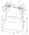
- FIG. 1 is an external perspective view of a prismatic secondary battery module according to Embodiment 1.
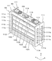
- FIG. FIG. 5 is an assembled perspective view of a pair of cell holders and a square secondary battery of the module shown in FIG. 4.
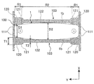
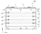
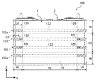
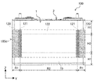
- the front view which shows the positional relationship of the spacer of a module shown in FIG. 4, and a square secondary battery.
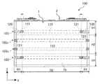
- the front view which shows the positional relationship of the square secondary battery and spacer of the module which concern on Embodiment 2.
- FIG. 5 is an assembled perspective view of a pair of cell holders and a square secondary battery of the module shown in FIG. 4.
- the front view which shows the positional relationship of the spacer of a module shown in FIG. 4, and a square secondary battery.
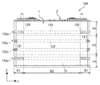
- the front view which shows the positional relationship of the square secondary battery and spacer
- FIG. 6 is a front view showing a positional relationship among a spacer, a square secondary battery, and a spacer of a module according to a fifth embodiment.
- FIG. 10 is an exploded perspective view of a module according to a sixth embodiment.
- FIG. 10 is a front view showing a positional relationship between a spacer and a prismatic secondary battery of a module according to a sixth embodiment.
- FIG. 10 is a front view showing a positional relationship between a spacer and a square secondary battery of a module according to a seventh embodiment.
- FIG. 10 is a front view showing a positional relationship between a spacer and a prismatic secondary battery of a module according to an eighth embodiment.
- FIG. 10 is a front view showing a positional relationship between a spacer of a module according to Embodiment 9 and a square secondary battery. The front view which shows the positional relationship of the spacer of the module which concerns on Example 10, and a square secondary battery.
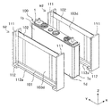
- FIG. 1 is an external perspective view of a prismatic secondary battery 100 as an embodiment of a power storage element
- FIG. 2 is an exploded perspective view showing the configuration of the prismatic secondary battery 100
- FIG. 3 is a developed perspective view of the wound group 3 provided in the prismatic secondary battery 100.
- the rectangular secondary battery 100 includes a battery container 2 including a battery can 1 and a battery lid 6.
- the material of the battery can 1 and the battery lid 6 is aluminum or an aluminum alloy.
- the battery can 1 is formed in a rectangular parallelepiped flat box shape with one surface opened by subjecting a metal material to deep drawing.
- the battery can 1 includes a rectangular bottom surface 1d, a pair of wide side surfaces 1b adjacent to each of the pair of long sides of the bottom surface 1d, and a pair of narrow side surfaces 1c adjacent to each of the pair of short sides of the bottom surface 1d. have.
- the battery lid 6 has a rectangular flat plate shape, and closes the opening of the battery can 1 and is laser-welded. That is, the battery lid 6 seals the opening of the battery can 1.
- the battery cover 6 is electrically connected to the positive electrode terminal component 60 electrically connected to the positive electrode 34 (see FIG. 3) of the wound group 3, and the negative electrode 32 (see FIG. 3) of the wound group 3.
- the negative electrode side terminal structure part 70 connected in general is provided.
- the positive electrode side terminal component 60 includes a positive electrode bolt 14, a positive electrode connection terminal 62, a positive electrode external terminal 63, a positive electrode side external insulator 24, a gasket (not shown) disposed inside the battery can 1, and a positive electrode current collector 180. Consists of The positive electrode bolt 14, the positive electrode external terminal 63, the positive electrode connection terminal 62, the gasket and the positive electrode current collector 180 are integrally fixed and attached to the battery lid 6. In this state, the positive electrode current collector 180, the positive electrode connection terminal 62, and the positive electrode external terminal 63 are electrically connected. The positive electrode current collector 180, the positive electrode connection terminal 62, and the positive electrode external terminal 63 are insulated from the battery lid 6 by the positive electrode side external insulator 24 and the gasket.
- the negative electrode side terminal component 70 includes a negative electrode bolt 12, a negative electrode connection terminal 72, a negative electrode external terminal 73, a negative electrode side external insulator 22, a gasket (not shown) disposed inside the battery can 1, and a negative electrode current collector 190. Consists of The negative electrode side terminal component 70 has the same structure as the positive electrode side terminal component 60, and the negative electrode bolt 12, the negative electrode external terminal 73, the negative electrode connection terminal 72, and the negative electrode current collector 190 are integrally fixed, and the battery cover 6 is attached. In this state, the negative electrode current collector 190, the negative electrode connection terminal 72, and the negative electrode external terminal 73 are electrically connected. The negative electrode current collector 190, the negative electrode connection terminal 72, and the negative electrode external terminal 73 are insulated from the battery lid 6 by the negative electrode side external insulator 22 and the gasket.
- each of the positive and negative bolts 14 and 12 protrudes from the battery lid 6 and has a screw structure. Therefore, when producing an assembled battery, the positive electrode bolt 14 or the negative electrode bolt 12 is inserted into a bus bar (not shown) provided with holes or notches, and assembled with a nut. Thereby, the positive electrode external terminal 63 or the negative electrode external terminal 73 and the bus bar are electrically connected.
- the battery cover 6 is provided with a gas discharge valve 10.
- the gas discharge valve 10 is formed by partially thinning the battery cover 6 by press working.
- the thin film member may be attached to the opening of the battery lid 6 by laser welding or the like, and the thin portion of the thin film member may be used as a gas discharge valve.
- the gas discharge valve 10 generates heat when the square secondary battery 100 generates heat due to an abnormality such as overcharge, and when the pressure in the battery container rises and reaches a predetermined pressure, the gas discharge valve 10 is opened and gas is discharged from the inside. By discharging, the pressure in the battery container is reduced.
- the battery lid 6 is provided with a liquid injection hole (not shown) for injecting the electrolyte into the battery container.
- the liquid injection hole is sealed with a liquid injection stopper 11 after the electrolytic solution is injected.
- the electrolytic solution for example, a non-aqueous electrolytic solution in which a lithium salt such as lithium hexafluorophosphate (LiPF 6 ) is dissolved in a carbonate-based organic solvent such as ethylene carbonate can be used.
- the battery can 1 contains a wound electrode group 3 (hereinafter also referred to as a wound group) held by the lid assembly 107.
- the positive electrode current collector 180 bonded to the positive electrode 34 (see FIG. 3) of the winding group 3 and the negative electrode current collector 190 bonded to the negative electrode 32 (see FIG. 3) of the winding group 3 and the winding group 3 Is housed in the battery can 1 while being covered with the insulating case 108.
- the material of the insulating case 108 is an insulating resin such as polypropylene, and the battery can 1 and the wound group 3 are electrically insulated by the insulating case 108.
- the insulating case 108 includes an insulating case wide portion 108a that covers the wide side surface of the wound group 3, and two insulating case side surface portions 108b that cover the side surface portion of the wound group 3.
- the wide part 108a and the insulating case side part 108b may be integrated.
- the lid assembly 107 includes a positive electrode current collector 180, a positive electrode connection terminal 62, a positive electrode external terminal 63, a positive electrode bolt 14, a positive electrode side external insulator 24, a negative electrode current collector 190, a negative electrode connection terminal 72, a negative electrode external terminal 73, a negative electrode
- the bolt 12, the negative electrode side external insulator 22, the gasket and the battery lid 6 are assembled together.
- the positive electrode external terminal 63 is electrically connected to the positive electrode 34 (see FIG. 3) of the winding group 3 via the positive electrode current collector 180, and the negative electrode external terminal 73 is connected to the winding group 3 via the negative electrode current collector 190.
- the negative electrode 32 (see FIG. 3) is electrically connected. As a result, power is supplied from the wound group 3 to the external device via the positive external terminal 63 and the negative external terminal 73, or external generated power is supplied to the external group 3 via the positive external terminal 63 and the negative external terminal 73. To be charged.
- the positive electrode current collector 180 is made of aluminum or an aluminum alloy.
- the positive electrode current collector 180 includes a flat plate-shaped seat surface portion 181 attached along the lower surface of the battery lid 6 and a pair of flat surface portions 182 that are bent downward at approximately 90 ° at both ends in the width direction of the seat surface portion 181. And a flat joint plane portion 183 formed at the tip of each of the pair of plane portions 182.
- Each joining plane part 183 is joined to the winding group 3 by ultrasonic welding.
- Each of the bonding flat portions 183 is bent at an angle inclined with respect to the flat portion 182.
- the pair of joining flat portions 183 are inclined so as to be separated from each other in the short side direction of the battery cover 6 as they move from the central side in the long side direction of the battery cover 6 toward the outside, and the inclination directions are opposite to each other. Although it is a direction, it is the same angle with respect to the center plane and is line symmetric.
- the pair of joining plane portions 183 are inserted between the positive foil exposed portions 34b of the wound group 3 and the positive foil exposed portions 34b of the wound group 3 are opened in a V-shape. Joined by ultrasonic welding.
- the negative electrode current collector 190 is formed of copper or a copper alloy, but has the same structure as the positive electrode current collector 180.
- the negative electrode current collector 190 includes a flat seat surface portion 191 attached along the lower surface of the battery lid 6 and a pair of flat surface portions 192 that are bent downward at approximately 90 ° at both ends in the width direction of the seat surface portion 191. And a flat joint plane portion 193 formed at the tip of each of the pair of plane portions 192.
- Each joining plane part 193 is joined to the winding group 3 by ultrasonic welding.
- Each of the bonding plane portions 193 is bent at an angle inclined with respect to the plane portion 192.
- the pair of joining flat portions 192 are inclined so as to be separated from each other in the short side direction of the battery cover 6 as they move from the center side in the long side direction of the battery cover 6 toward the outside, and the inclination directions are opposite to each other. Although it is a direction, it is the same angle with respect to the center plane and is line symmetric.
- the pair of bonding flat portions 193 is inserted into the negative electrode foil exposed portion 32b with the negative foil exposed portion 32b of the wound group 3 inserted between them and the negative foil exposed portion 32b of the wound group 3 opened in a V shape. Joined by ultrasonic welding.
- FIG. 3 shows a state where the winding end side of the wound group 3 is developed.
- the winding group 3 which is a power generation element, has a laminated structure in which a long positive electrode 34 and a negative electrode 32 are wound in a flat shape around the winding center axis W with separators 33 and 35 interposed therebetween. ing.
- the positive electrode 34 has a positive electrode mixture layer 34a in which a positive electrode active material mixture is applied to both surfaces of a positive electrode foil that is a positive electrode current collector, and a positive electrode active material compound is formed at one end in the width direction of the positive electrode foil. There is provided a positive foil exposed portion 34b to which no agent is applied.
- the negative electrode 32 has a negative electrode mixture layer 32a in which a negative electrode active material mixture is applied to both surfaces of a negative electrode foil that is a negative electrode current collector, and the negative electrode active material mixture is formed at the other end in the width direction of the negative electrode foil.
- the negative electrode foil exposed part 32b which does not apply
- the positive electrode foil exposed portion 34b and the negative electrode foil exposed portion 32b are regions where the metal surface of the electrode foil is exposed, and are disposed at positions on one side and the other side in the winding central axis W direction (width direction in FIG. 3). To be wound up.
- negative electrode 32 10 parts by weight of polyvinylidene fluoride (hereinafter referred to as PVDF) is added as a binder to 100 parts by weight of amorphous carbon powder as a negative electrode active material, and N as a dispersion solvent.
- NMP kneading methylpyrrolidone
- amorphous carbon is used as the negative electrode active material, but the present invention is not limited to this.
- Natural graphite capable of inserting and removing lithium ions and various artificial graphite materials Carbonaceous materials such as coke, compounds such as Si and Sn (for example, SiO, TiSi2 etc.), or composite materials thereof may be used, and the particle shape is particularly limited, such as scaly, spherical, fibrous, or massive Is not to be done.
- the positive electrode 34 10 parts by weight of flaky graphite as a conductive material and 10 parts by weight of PVDF as a binder are added to 100 parts by weight of lithium manganate (chemical formula LiMn 2 O 4 ) as a positive electrode active material.
- a positive electrode mixture was prepared by adding and kneading NMP as a dispersion solvent. This positive electrode material mixture was applied to both surfaces of an aluminum foil (positive electrode foil) having a thickness of 20 ⁇ m, leaving the welded portion (positive electrode foil exposed portion 34b). Thereafter, a positive electrode 34 having a thickness of 90 ⁇ m in the thickness of the positive electrode active material coating portion not including an aluminum foil was obtained through drying, pressing, and cutting processes.
- lithium manganate is used as the positive electrode active material
- other lithium manganate having a spinel crystal structure or a lithium manganese composite oxide or layered in which a part is substituted or doped with a metal element A lithium cobalt oxide or lithium titanate having a crystal structure, or a lithium-metal composite oxide obtained by substituting or doping a part thereof with a metal element may be used.
- PVDF polytetrafluoroethylene
- PTFE polytetrafluoroethylene
- Polymers such as nitrile rubber, styrene butadiene rubber, polysulfide rubber, nitrocellulose, cyanoethyl cellulose, various latexes, acrylonitrile, vinyl fluoride, vinylidene fluoride, propylene fluoride, chloroprene fluoride, acrylic resins, and mixtures thereof Etc.
- One of the end portions of the winding group 3 in the width direction is a laminated portion of the positive electrode 34, and the other is a laminated portion of the negative electrode 32.
- the stacked portion of the positive electrode 34 provided at one end is formed by stacking the positive foil exposed portion 34b where the positive electrode mixture layer 34a is not formed.
- the laminated portion of the negative electrode 32 provided at the other end is obtained by laminating a negative foil exposed portion 32b where the negative electrode mixture layer 32a is not formed.
- the laminated portion of the positive electrode foil exposed portion 34b and the laminated portion of the negative electrode foil exposed portion 32b are respectively crushed in advance, and are ultrasonically bonded to the positive electrode current collector 180 and the negative electrode current collector 190 of the lid assembly 107 as described above. To form an electrode assembly.
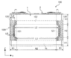
- FIG. 4 is a perspective view showing the module 200 of the present embodiment.
- the rectangular secondary battery 100 when the module 200 is manufactured will be described using an orthogonal coordinate system in which the thickness, width, and height directions are the X, Y, and Z directions, respectively.
- the module 200 includes a plurality of rectangular secondary batteries 100 stacked in the thickness direction (X direction), and a cell holder 91 that holds each rectangular secondary battery 100 in a stacked state.
- the cell holder 91 can be made of, for example, a resin material such as glass epoxy resin, polypropylene, or polybutylene terephthalate resin, or a metal material such as aluminum, copper, or stainless steel.
- the cell holder 91 includes a plurality of intermediate cell holders 92 and a pair of end cell holders 93.
- Intermediate cell holder 92 is interposed between prismatic secondary batteries 100 adjacent to each other.
- the end cell holders 93 are arranged at both ends in the stacking direction of the plurality of prismatic secondary batteries 100 held by the intermediate cell holder 92, and hold the prismatic secondary battery 100 between the intermediate cell holders 92.
- the end cell holder 93 has a shape in which the intermediate cell holder 92 is roughly divided into two parts parallel to the wide side surface 1 b of the prismatic secondary battery 100.
- the plurality of spacers 101, 102, 103 and the openings 111a, 111b provided in the intermediate cell holder 92 and the end cell holder 93 will be described later.
- FIG. 5 is a perspective view showing an assembled state of the pair of intermediate cell holders 92 and the prismatic secondary battery 100.
- FIG. 6 is a perspective view showing an exploded state of the pair of intermediate cell holders 92 and the prismatic secondary battery 100 shown in FIG.
- the intermediate cell holder 92 includes a pair of side plates 111, 111 facing the pair of narrow side surfaces 1 c, 1 c of the battery can 1 of the square secondary battery 100, and the bottom surface of the battery can 1. 1d and a bottom plate 112 facing each other.
- the intermediate cell holder 92 Since the intermediate cell holder 92 is disposed between the two rectangular secondary batteries 100, the intermediate cell holder 92 has a shape symmetrical to a plane passing through the middle of the two rectangular secondary batteries 100 and parallel to the wide side surface 1 b of the battery can 1. ing. Therefore, the side plate 111 and the bottom plate 112 of the intermediate cell holder 92 are respectively arranged in the thickness direction of the battery can 1 with respect to the narrow side surface 1c and the bottom surface 1d of the two rectangular secondary batteries 100 arranged on both sides of the intermediate cell holder 92. It is facing about half each.
- the pair of side plates 111, 111 are opposed to each other in the width direction (Y direction) of the wide side surface 1 b of the battery can 1, that is, both ends in the width direction of the rectangular secondary battery 100, and the stacking direction (X Direction), that is, extending in the thickness direction of the prismatic secondary battery 100.
- the bottom plate 112 extends in the stacking direction of the rectangular secondary battery 100 in the direction perpendicular to the bottom surface 1 d (Z direction) of the battery can 1, that is, the lower end in the height direction of the rectangular secondary battery 100, and has two side plates 111. The lower ends of the are connected.
- the two intermediate cell holders 92 and 92 disposed on both sides of the rectangular secondary battery 100 are held with the end portions of the side plates 111 and 111 and the bottom plates 112 and 112 being abutted or slightly spaced from each other. Thus, a space for holding the prismatic secondary battery 100 is formed between them.
- the pair of side plates 111, 111 are connected by a plurality of spacers 101, 102, 103. More specifically, the pair of side plates 111, 111 includes a lower end spacer 101 that connects these lower ends, an upper end spacer 102 that connects these upper ends, and an intermediate spacer 103 that connects these intermediate portions. It is connected by.
- the lower end spacer 101 is connected to the bottom plate 112 at the lower end.
- the upper end spacer 102 corresponds to the height of the portion from the battery lid 6 to the curved portion on the battery lid 6 side of the wound group 3 built in the battery can 1, and has a width in the Z direction as compared with other spacers. It is getting wider.
- the interval between the lower end spacer 101 and the intermediate spacer 103 and the interval between the upper end spacer 102 and the intermediate spacer 103 are smaller than the interval between the intermediate spacers 103.
- Each spacer 101, 102, 103 is disposed between two adjacent battery cans 1. That is, in the module 200, the square secondary battery 100 is laminated with the spacers 101, 102, and 103 interposed in the thickness direction.
- the side plate 111 has a first opening 111a and a second opening 111b.
- the first opening 111 a is formed at a position between the lower end spacer 101 and the intermediate spacer 103 and a position between the upper end spacer 102 and the intermediate spacer 103 in the Z direction.
- the second opening 111b is formed at a position between the intermediate spacers 103 in the Z direction.
- the first opening 111a and the second opening 111b have the same opening width in the X direction.
- the opening height in the Z direction of each opening is greater in the second opening 111b than in the first opening 111a, corresponding to the spacing between the spacers 101, 102, 103.
- the spacers 101, 102, and 103 are spaced apart from each other in the Z direction, and thereby a plurality of slits extending in the width direction (Y direction) along the wide side surface 1 b of the battery can 1 of the rectangular secondary battery 100. 114 and 115 are formed.
- the width in the Z direction is relatively small between the lower end spacer 101 and the intermediate spacer 103 and between the upper end spacer 102 and the intermediate spacer 103 corresponding to the distance between the spacers 101, 102, and 103.
- a narrow first slit 114 is formed.
- a second slit 115 having a relatively wide width in the Z direction is formed between the intermediate spacers 103.
- the first slit 114 communicates the first openings 111 a of the two side plates 111
- the second slit 115 communicates the second openings 111 b of the two side plates 111.
- a cooling medium is allowed to pass through the slits 114 and 115 so that the wide side surface 1b of the battery can 1 of the rectangular secondary battery 100 can be cooled.
- FIG. 7 is a perspective view showing an assembled state of the pair of intermediate cell holders 92 and 92 and the prismatic secondary battery 100 shown in FIG. 5, and a cross section in which the intermediate cell holders 92 and 92 are cut along the XY plane so as to include the intermediate spacer 103.
- FIG. 7 is a perspective view showing an assembled state of the pair of intermediate cell holders 92 and 92 and the prismatic secondary battery 100 shown in FIG. 5, and a cross section in which the intermediate cell holders 92 and 92 are cut along the XY plane so as to include the intermediate spacer 103.
- the spacer 103 is divided into a plurality in the height direction (Z direction) of the wide side surface 1b of the battery can 1. Specifically, in the example shown in FIGS. 5 and 6, the spacer 103 is divided into four. As shown in FIG. 7, the spacer 103 includes a contact portion 120 that contacts the width direction end region R ⁇ b> 1 of the wide side surface 1 b of the battery can 1 constituting the battery case 2, and a width direction intermediate region R ⁇ b> 2 of the wide side surface 1 b. It has the opposing part 122 which opposes, and the inclined surface 121 adjacent to the both ends of the opposing part 122 in the width direction (Y direction) of the wide side surface 1b.
- the width direction end region R1 is a region having a predetermined width narrower than the width from the width direction end of the wide side surface 1b of the battery can 1 to the width direction center, and the width direction intermediate region R2 is The region between the width direction end region R1.
- the contact portions 120 are provided at both end portions of the spacer 103 in the width direction of the wide side surface 1b, and protrude toward the wide side surface 1b of the rectangular secondary battery 100 from the facing portion 122. That is, the thickness T1 of the contact portion 120 in the thickness direction (X direction) of the rectangular secondary battery 100 is greater than the thickness T2 of the facing portion 122 in the same direction. Thereby, in the pair of spacers 103 and 103 facing each other, the distance D1 between the contact parts 120 and 120 is narrower than the distance D2 between the facing parts 122 and 122. In other words, the distance D2 between the facing parts 122, 122 is wider than the distance D1 between the contact parts 120, 120. Further, the surfaces of the contact portion 120 and the facing portion 122 facing the wide side surface 1b of the battery can 1 are flat surfaces parallel to the width direction (Y direction) and the height direction (Z direction) of the rectangular secondary battery 100. Has been.
- the contact portions 120 are provided at both ends of each of the four spacers 103 and contact the width direction end region R1 of the wide side surface 1b of the battery can 1.
- the facing part 122 faces the intermediate region R2 in the width direction of the wide side surface 1b.
- an inclined surface 121 is provided inside the contact portion 120, and a facing portion 122 is provided inside the inclined surface 121.
- the inclined surface 121 abuts in the width direction (Y direction) of the wide side surface 1b at the position facing the entire height direction (Z direction) of the wide side surface 1b, that is, the height direction end region H1 and the intermediate region H2. It is provided between the portion 120 and the facing portion 122.
- the inclined surface 121 when the inclination angle of the inclined surface 121 with respect to the width direction (Y direction) of the wide side surface 1b of the battery can 1 is smaller than the inclination angle of the wide side surface 1b due to the expansion of the battery can 1, the inclined surface 121 is changed to the wide side surface. In addition to suppressing the expansion of the wide side surface 1b, the stress acting on the wide side surface 1b can be reduced as compared with the case where the inclined surface 121 is not formed. Further, if the inclination angle of the inclined surface 121 is approximately the same as the inclination angle of the wide side surface 1b of the battery can 1, the entire inclined surface 121 is substantially brought into contact with the wide side surface 1b and acts on the wide side surface 1b. The stress can be further reduced.
- the inclination angle of the inclined surface 121 is larger than the inclination angle of the wide side surface 1b, the contact between the spacer 103 and the wide side surface 1b is avoided between the contact portion 120 and the facing portion 122, and the inclined surface Stress concentration is prevented from occurring between 121 and the wide side surface 1 b of the battery can 1.
- the distance D ⁇ b> 2 between the pair of facing portions 122, 122 is such that when the battery can 1 is expanded such that the battery performance of the prismatic secondary battery 100 is deteriorated, the facing portion 122 has the wide side surface of the battery can 1. It is set to abut against 1b and suppress the expansion of the battery can 1. Therefore, when the battery can 1 does not expand so as to adversely affect the battery performance, the facing portion 122 does not contact the wide side surface 1b of the battery can 1.
- the width direction end region R1 of the wide side surface 1b of the battery can 1 that constitutes the battery container 2 of the prismatic secondary battery 100. Can be securely held between the contact portions 120, 120 of the spacers 103, 103, and the positioning accuracy of the prismatic secondary battery 100 can be improved. Further, while the stress concentration on the wide side surface 1b is suppressed by the inclined surface 121, the expansion of the battery case 2 can be suppressed by the facing portion 122 that faces the intermediate region R2 in the width direction of the wide side surface 1b.
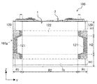
- FIG. 9 is a front view showing the positional relationship between the prismatic secondary battery 100 and the intermediate spacers 103 and 103a of the prismatic secondary battery module, which is the assembled battery of the present embodiment, corresponding to FIG. 8 of the first embodiment. .
- the module of the present embodiment is different from the intermediate portion spacer 103 of the first embodiment described above in the configuration of the intermediate portion spacer 103a included in the intermediate portion cell holder 92 and the end portion cell holder 93 constituting the cell holder 91. Since the other points of the module of the present embodiment are the same as those of the module 200 of the first embodiment, the same portions are denoted by the same reference numerals and description thereof is omitted.
- the two spacers 103 and 103 facing the height direction intermediate region H2 of the wide side surface 1b of the battery can 1 have the same configuration as the spacer 103 of the first embodiment.
- the two spacers 103a and 103a facing the height direction end regions H1 and H1 of the wide side surface 1b of the battery can 1 are different from the spacer 103 of the first embodiment in that the inclined surface 121 is not formed. ing.
- the inclined surface 121 provided on the spacers 103 and 103 is a position facing the intermediate region H2 in the height direction of the wide side surface 1b of the battery can 1, and the width direction (Y direction) of the wide side surface 1b. 1 is provided between the contact portion 120 and the facing portion 122.
- the length L0 of the contact portion 120 in the width direction of the wide side surface 1b of the spacer 103a facing the height direction end region H1 of the wide side surface 1b is the same direction of the contact portion 120 of the spacer 103 therebetween. Longer than L0. That is, the length L0 of the contact portion 120 along the width direction of the wide side surface 1b is gradually increased in the direction from the height direction intermediate region H2 to the height direction end region H1.
- the thickness of the battery can 1 when the battery can 1 expands is greatest at the center in the height direction (Z direction) and the width direction (Y direction) of the wide side surface 1b of the battery can 1, and at the end in each direction. It gets smaller as you go. Therefore, stress concentration may not occur in the battery can 1 even if the inclined surface 121 is not formed in the spacer 103a facing the height direction end region H1 as in the module of the present embodiment.
- the module 200 of the first embodiment includes the spacer 103 having the same configuration as that of the first embodiment facing the intermediate region in the height direction of the wide side surface 1b of the battery can 1. Similar effects can be obtained.
- the length L0 of the contact portion 120 along the width direction of the wide side surface 1b is gradually increased in the direction from the intermediate region H2 in the height direction toward the end region H1 in the height direction.
- the width direction end region R1 of the wide side surface 1b can be more reliably held by the relatively long contact portion 120 of the spacer 103a.
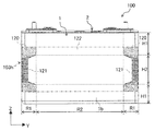
- FIG. 10 is a front view showing the positional relationship between the prismatic secondary battery 100 and the intermediate spacers 103 and 103b of the prismatic secondary battery module, which is the assembled battery of the present embodiment, corresponding to FIG. 8 of the first embodiment. .
- the length L0 in the same direction of the contact portion 120 of the spacer 103 facing the height direction end region H1 is the length in the same direction of the contact portion 120 of the spacer 103b facing the intermediate region H2 in the height direction. Longer than L0. That is, the length L0 of the contact portion 120 along the width direction of the wide side surface 1b of the battery can 1 is gradually increased in the direction from the height direction intermediate region H2 to the height direction end region H1. Since the other points of the module of the present embodiment are the same as those of the module 200 of the first embodiment, the same portions are denoted by the same reference numerals and description thereof is omitted.
- the thickness of the battery can 1 when the battery can 1 expands is the largest in the height direction and the center in the width direction of the wide side surface 1b of the battery can 1, and the thickness decreases toward the end in each direction.
- the module of the present embodiment not only the same effects as the module 200 of the first embodiment described above can be obtained, but also the length L0 of the contact portion 120 is increased from the height direction intermediate region H2 of the wide side surface 1b.
- the width direction end region R1 can be more reliably held by the relatively long contact portion 120 in the height direction end region H1 of the battery can 1. it can.
- the length L2 of the facing portion 122 along the width direction of the wide side surface 1b of the battery can 1 is gradually increased in the direction from the height direction end region H1 to the height direction intermediate region H2.
- the position of the contact portion 120 is close to both end portions of the spacer 103b. Therefore, in the height direction intermediate region H2, the stress concentration in the width direction end region R1 of the wide side surface 1b of the battery can 1 can be further relaxed.
- FIG. 11 is a front view showing the positional relationship between the prismatic secondary battery 100 and the intermediate spacers 103 and 103c of the prismatic secondary battery module, which is the assembled battery of the present embodiment, corresponding to FIG. 8 of the first embodiment. .
- the inclined surface 121 is provided between the contact portion 120 and the facing portion 122 in the width direction of the wide side surface 1b.
- the inclined surfaces 121 are provided at both ends in the width direction of the wide side surface 1b of the battery can 1. Since the other points of the module of the present embodiment are the same as those of the module 200 of the first embodiment, the same portions are denoted by the same reference numerals and description thereof is omitted.
- the thickness of the battery can 1 when the battery can 1 expands is the largest in the height direction and the center in the width direction of the wide side surface 1b of the battery can 1, and the thickness decreases toward the end in each direction.
- the spacer 103 having the same configuration as that of the first embodiment is provided at a position facing the height direction end region H1 of the wide side surface 1b of the battery can 1, and the spacer 103c facing the height direction intermediate region H2 is in contact.
- FIG. 12 is a front view showing the positional relationship between the prismatic secondary battery 100 and the intermediate spacers 103a and 103c of the prismatic secondary battery module, which is the assembled battery of the present embodiment, corresponding to FIG. 8 of the first embodiment. .
- the spacer 103a facing the height direction end region H1 of the wide side surface 1b of the battery can 1 has the same configuration as the spacer 103a of the above-described second embodiment, and the height of the wide side surface 1b.
- the spacer 103c facing the vertical intermediate region H2 has the same configuration as the spacer 103c of the fourth embodiment described above.
- the spacer 103a at a position facing the height direction end region H1 has the contact portion 120 and the facing portion 122 and does not have the inclined surface 121.
- the spacer 103c at a position facing the intermediate region H2 in the height direction has the inclined surface 121 and the facing portion 122, and does not have the contact portion 120. Since the other points of the module of the present embodiment are the same as those of the module 200 of the first embodiment, the same portions are denoted by the same reference numerals and description thereof is omitted.
- the thickness of the battery can 1 when the battery can 1 expands is the largest in the height direction and the center in the width direction of the wide side surface 1b of the battery can 1, and the thickness decreases toward the end in each direction.
- the spacer 130a at the position facing the height direction end region H1 of the wide side surface 1b of the battery can 1 has the same configuration as the spacer 130a of the second embodiment, and the middle in the height direction. Since the spacer 103c at the position facing the region H2 has the same configuration as the spacer 103c of the fourth embodiment, not only can the same effect as the module 200 of the first embodiment be obtained, but also the modules of the second and fourth embodiments. Similar effects can be obtained.
- the intermediate spacer 103d of the module of the present embodiment is integrally provided in the height direction (Z direction) of the rectangular secondary battery 100, the lower end is connected to the lower end spacer 101, and the upper end is connected to the upper end spacer 102.
- the intermediate cell holder 92 and the end cell holder 93 include notches 112 a for cooling the square secondary battery 100 on the bottom plate 112 in place of the openings 111 a and 111 b and the slits 114 and 115 of the side plate 111. Yes.
- the notch 112a exposes the bottom surface 1d of the battery can 1 from the bottom plate 112 of the cell holders 92 and 93 when the prismatic secondary battery 100 is assembled into the cell holder 91, thereby allowing the prismatic secondary battery 100 to be cooled. Yes. Since the other points of the module of the present embodiment are the same as those of the module 200 of the first embodiment, the same portions are denoted by the same reference numerals and description thereof is omitted.
- the spacer 103d of this embodiment has the same configuration as the spacer 103 of Embodiment 1 shown in FIGS. 7 and 8 except that the spacer 103d is integrally provided in the height direction of the prismatic secondary battery 100.
- the spacer 103d includes an abutment portion 120 that abuts on the width direction end region R1 of the wide side surface 1b of the battery can 1, an opposing portion 122 that opposes the width direction intermediate region R2 of the wide side surface 1b, and the battery can 1. It has the inclined surface 121 adjacent to the both ends of the opposing part 122 in the width direction of the wide side surface 1b.
- the inclined surface 121 is inclined so that the thickness of the spacer 103d decreases in the direction from the width direction end region R1 toward the width direction intermediate region R2. Thereby, the inclined surface 121 inclines along the wide side surface 1b of the battery can 1 which expanded in the convex curved surface shape where the thickness of the center part becomes the thickest. Therefore, when the wide side surface 1b of the expanded battery can 1 is pressed by the contact portion 120 or the facing portion 122 of the spacer 103d, it is possible to prevent stress concentration from occurring on the wide side surface 1b of the battery can 1 due to the spacer 103. Therefore, it is possible to improve both the reliability of the battery can 1 and suppress the deterioration of battery performance.
- the width direction end region R1 of the wide side surface 1b of the battery can 1 constituting the battery container 2 of the prismatic secondary battery 100 is the spacer 103d. , 103d can be securely held between the contact portions 120, 120, and the positioning accuracy of the rectangular secondary battery 100 can be improved. Further, while the stress concentration on the wide side surface 1b is suppressed by the inclined surface 121, the expansion of the battery case 2 can be suppressed by the facing portion 122 that faces the intermediate region R2 in the width direction of the wide side surface 1b.
- the wide side surface 1b of the battery can 1 is pressed by the spacer 103d having a large area integrally formed as compared with the spacer 103 of the first embodiment divided into a plurality of parts, the battery can 1 can be more reliably attached. Expansion of the wide side surface 1b can be suppressed, and deterioration of battery performance can be suppressed more reliably.
- the intermediate spacer 103e is integrally provided in the height direction of the rectangular secondary battery 100, the same effect as that of the intermediate spacer 103d of Embodiment 6 can be obtained.
- the spacer of the second embodiment Similarly to 103a, in the height direction end region H1 of the wide side surface 1b of the battery can 1, the width direction end region R1 can be more reliably held by the contact portion 120 of the spacer 103a.
- FIG. 17 is a front view showing the positional relationship between the prismatic secondary battery 100 and the intermediate spacer 103g of the module of the present embodiment, which corresponds to FIG. 8 of the first embodiment.
- the intermediate spacer 103g is integrally provided in the height direction of the square secondary battery 100, the same effect as that of the module of the sixth embodiment can be obtained.
- the inclined surface 121 is provided between the contact portion 120 and the facing portion 122 at a position facing the height direction end region H1 of the wide side surface 1b, and at a position facing the height direction intermediate region H2. Since it is provided at both ends in the width direction, the same effect as the module of the fourth embodiment can be obtained.
- the intermediate spacer 103h has an abutting portion 120 and an opposing portion 122 at a position facing the height direction end region H1, and is inclined. There is no surface 121.
- the intermediate spacer 103h has an inclined surface 121 and an opposing portion 122 at a position facing the intermediate region H2 in the height direction. I don't have it.
- Battery can (battery container) 1b Wide side surface 2 Battery container 3 Winding group (electrode group) 6 Battery cover (battery container) 32 Negative electrode 34 Positive electrode 100 Square secondary battery 103 Spacer 120 Abutting portion 121 Inclined surface 122 Opposing portion 200 Module (assembled battery) L0 Length of contact portion L2 Length of opposite portion R1 Width direction end region R2 Width direction intermediate region H1 Height direction end region H2 Height direction intermediate region X Thickness direction Y Width direction Z Height direction
Landscapes
- Chemical & Material Sciences (AREA)
- Chemical Kinetics & Catalysis (AREA)
- Electrochemistry (AREA)
- General Chemical & Material Sciences (AREA)
- Engineering & Computer Science (AREA)
- Manufacturing & Machinery (AREA)
- Battery Mounting, Suspending (AREA)
- Secondary Cells (AREA)
Priority Applications (3)
| Application Number | Priority Date | Filing Date | Title |
|---|---|---|---|
| EP14849377.8A EP3051606B1 (de) | 2013-09-24 | 2014-08-06 | Zusammengesetzte zelle |
| US14/914,282 US10651442B2 (en) | 2013-09-24 | 2014-08-06 | Assembled cell |
| CN201480049247.0A CN105518904B (zh) | 2013-09-24 | 2014-08-06 | 电池组 |
Applications Claiming Priority (2)
| Application Number | Priority Date | Filing Date | Title |
|---|---|---|---|
| JP2013196990A JP6166994B2 (ja) | 2013-09-24 | 2013-09-24 | 組電池 |
| JP2013-196990 | 2013-09-24 |
Publications (1)
| Publication Number | Publication Date |
|---|---|
| WO2015045632A1 true WO2015045632A1 (ja) | 2015-04-02 |
Family
ID=52742788
Family Applications (1)
| Application Number | Title | Priority Date | Filing Date |
|---|---|---|---|
| PCT/JP2014/070663 WO2015045632A1 (ja) | 2013-09-24 | 2014-08-06 | 組電池 |
Country Status (5)
| Country | Link |
|---|---|
| US (1) | US10651442B2 (de) |
| EP (1) | EP3051606B1 (de) |
| JP (1) | JP6166994B2 (de) |
| CN (1) | CN105518904B (de) |
| WO (1) | WO2015045632A1 (de) |
Cited By (3)
| Publication number | Priority date | Publication date | Assignee | Title |
|---|---|---|---|---|
| WO2016132897A1 (ja) * | 2015-02-19 | 2016-08-25 | 日立オートモティブシステムズ株式会社 | 組電池 |
| CN106340685A (zh) * | 2015-07-13 | 2017-01-18 | 宁德时代新能源科技股份有限公司 | 二次电池用夹具 |
| CN107851756A (zh) * | 2015-09-30 | 2018-03-27 | 松下知识产权经营株式会社 | 电池模块 |
Families Citing this family (27)
| Publication number | Priority date | Publication date | Assignee | Title |
|---|---|---|---|---|
| KR102230556B1 (ko) | 2012-08-16 | 2021-03-22 | 에노빅스 코오퍼레이션 | 3차원 배터리들을 위한 전극 구조들 |
| EP3641030B1 (de) | 2013-03-15 | 2022-03-02 | Enovix Corporation | Dreidimensionale batterien |
| JP6166994B2 (ja) * | 2013-09-24 | 2017-07-19 | 日立オートモティブシステムズ株式会社 | 組電池 |
| US10164296B2 (en) * | 2015-03-12 | 2018-12-25 | Johnson Controls Technology Company | Battery module separator plates |
| JP6547407B2 (ja) * | 2015-05-18 | 2019-07-24 | 株式会社豊田自動織機 | 蓄電装置モジュール |
| EP3828976B1 (de) | 2015-05-14 | 2023-07-05 | Enovix Corporation | Längsbeschränkungen für energiespeichervorrichtungen |
| SG11201809308QA (en) | 2016-05-13 | 2018-11-29 | Enovix Corp | Dimensional constraints for three-dimensional batteries |
| US10873111B2 (en) * | 2016-08-09 | 2020-12-22 | Wisk Aero Llc | Battery with compression and prevention of thermal runaway propagation features |
| JP7086978B2 (ja) | 2016-11-16 | 2022-06-20 | エノビクス・コーポレイション | 圧縮性カソードを備えた3次元電池 |
| JP6878975B2 (ja) * | 2017-03-17 | 2021-06-02 | 三洋電機株式会社 | 組電池 |
| WO2019071184A1 (en) * | 2017-10-06 | 2019-04-11 | Johnson Controls Technology Company | LITHIUM ION BATTERY |
| JP6926946B2 (ja) * | 2017-10-26 | 2021-08-25 | トヨタ自動車株式会社 | 組電池 |
| US10256507B1 (en) | 2017-11-15 | 2019-04-09 | Enovix Corporation | Constrained electrode assembly |
| KR20200074246A (ko) | 2017-11-15 | 2020-06-24 | 에노빅스 코오퍼레이션 | 전극 어셈블리 및 2차 배터리 |
| US10756398B2 (en) | 2018-06-22 | 2020-08-25 | Wisk Aero Llc | Capacitance reducing battery submodule with thermal runaway propagation prevention and containment features |
| US11211639B2 (en) | 2018-08-06 | 2021-12-28 | Enovix Corporation | Electrode assembly manufacture and device |
| US10593920B2 (en) | 2018-08-13 | 2020-03-17 | Wisk Aero Llc | Capacitance reduction in battery systems |
| EP3951818A4 (de) * | 2019-03-28 | 2022-06-01 | GS Yuasa International Ltd. | Stromspeichervorrichtung |
| DE102019211253A1 (de) * | 2019-07-29 | 2021-02-04 | Elringklinger Ag | Galvanische Zellen und Batteriemodule |
| CN111029488B (zh) * | 2019-08-14 | 2021-07-30 | 宁德时代新能源科技股份有限公司 | 二次电池 |
| CN110676518B (zh) * | 2019-09-19 | 2020-06-26 | 宜宾锂宝新材料有限公司 | 一种防止锂离子电池负极析锂的方法 |
| CN111564585B (zh) * | 2020-04-27 | 2022-10-14 | 先进储能材料国家工程研究中心有限责任公司 | 方形电池模组 |
| CN111490208B (zh) * | 2020-04-27 | 2023-01-17 | 先进储能材料国家工程研究中心有限责任公司 | 储能电池箱 |
| KR20220017741A (ko) * | 2020-08-05 | 2022-02-14 | 주식회사 엘지에너지솔루션 | 셀 스웰링을 흡수할 수 있는 구조를 갖는 배터리 모듈, 그리고 이를 포함하는 배터리 팩 및 자동차 |
| US11394076B2 (en) * | 2020-09-15 | 2022-07-19 | Lithium Power Inc. | Battery pack with a plurality of battery cells |
| EP4200921A1 (de) | 2020-09-18 | 2023-06-28 | Enovix Corporation | Verfahren zur abgrenzung einer population von elektrodenstrukturen in einem gewebe mit einem laserstrahl |
| KR20230122050A (ko) | 2020-12-09 | 2023-08-22 | 에노빅스 코오퍼레이션 | 2차 배터리용 전극 조립체의 제조를 위한 방법 및 장치 |
Citations (11)
| Publication number | Priority date | Publication date | Assignee | Title |
|---|---|---|---|---|
| JP2006048996A (ja) * | 2004-08-02 | 2006-02-16 | Toyota Motor Corp | 組電池 |
| JP2006310309A (ja) * | 2005-04-26 | 2006-11-09 | Samsung Sdi Co Ltd | 電池モジュール |
| JP2007115437A (ja) * | 2005-10-18 | 2007-05-10 | Toyota Motor Corp | 電池モジュール構造 |
| JP2009110833A (ja) * | 2007-10-31 | 2009-05-21 | Sanyo Electric Co Ltd | 電池パック及び電池パック用セパレータ |
| JP2011151013A (ja) * | 2009-12-25 | 2011-08-04 | Gs Yuasa Corp | 単電池およびこの単電池を用いた組電池 |
| WO2011158341A1 (ja) | 2010-06-16 | 2011-12-22 | トヨタ自動車株式会社 | 二次電池アセンブリ |
| JP2013033686A (ja) * | 2011-08-03 | 2013-02-14 | Toyota Motor Corp | 電池モジュール |
| JP2013073917A (ja) * | 2011-09-29 | 2013-04-22 | Lithium Energy Japan:Kk | 組電池 |
| WO2013084290A1 (ja) * | 2011-12-06 | 2013-06-13 | 日立ビークルエナジー株式会社 | 組電池 |
| JP2013149523A (ja) * | 2012-01-20 | 2013-08-01 | Gs Yuasa Corp | 蓄電素子モジュール |
| JP2014010983A (ja) * | 2012-06-28 | 2014-01-20 | Sanyo Electric Co Ltd | 電源装置及びこの電源装置を備える車両並びに蓄電装置 |
Family Cites Families (8)
| Publication number | Priority date | Publication date | Assignee | Title |
|---|---|---|---|---|
| JP4457931B2 (ja) * | 2005-03-17 | 2010-04-28 | トヨタ自動車株式会社 | 電池モジュール |
| JP2008282648A (ja) * | 2007-05-10 | 2008-11-20 | Toyota Motor Corp | 組電池 |
| JP5169471B2 (ja) * | 2008-05-16 | 2013-03-27 | トヨタ自動車株式会社 | 蓄電装置及び車両 |
| CN101814623A (zh) * | 2009-02-20 | 2010-08-25 | 日立麦克赛尔株式会社 | 电池组件以及电池组件的制造方法 |
| JP5645675B2 (ja) * | 2011-01-07 | 2014-12-24 | 三菱電機株式会社 | 分散シミュレーションシステム |
| US9356268B2 (en) * | 2011-01-10 | 2016-05-31 | Samsung Sdi Co., Ltd. | Battery module |
| WO2013080338A1 (ja) * | 2011-11-30 | 2013-06-06 | 日立ビークルエナジー株式会社 | 電池ブロック及びそれを有する電池モジュール |
| JP6166994B2 (ja) * | 2013-09-24 | 2017-07-19 | 日立オートモティブシステムズ株式会社 | 組電池 |
-
2013
- 2013-09-24 JP JP2013196990A patent/JP6166994B2/ja active Active
-
2014
- 2014-08-06 WO PCT/JP2014/070663 patent/WO2015045632A1/ja active Application Filing
- 2014-08-06 CN CN201480049247.0A patent/CN105518904B/zh active Active
- 2014-08-06 US US14/914,282 patent/US10651442B2/en active Active
- 2014-08-06 EP EP14849377.8A patent/EP3051606B1/de active Active
Patent Citations (11)
| Publication number | Priority date | Publication date | Assignee | Title |
|---|---|---|---|---|
| JP2006048996A (ja) * | 2004-08-02 | 2006-02-16 | Toyota Motor Corp | 組電池 |
| JP2006310309A (ja) * | 2005-04-26 | 2006-11-09 | Samsung Sdi Co Ltd | 電池モジュール |
| JP2007115437A (ja) * | 2005-10-18 | 2007-05-10 | Toyota Motor Corp | 電池モジュール構造 |
| JP2009110833A (ja) * | 2007-10-31 | 2009-05-21 | Sanyo Electric Co Ltd | 電池パック及び電池パック用セパレータ |
| JP2011151013A (ja) * | 2009-12-25 | 2011-08-04 | Gs Yuasa Corp | 単電池およびこの単電池を用いた組電池 |
| WO2011158341A1 (ja) | 2010-06-16 | 2011-12-22 | トヨタ自動車株式会社 | 二次電池アセンブリ |
| JP2013033686A (ja) * | 2011-08-03 | 2013-02-14 | Toyota Motor Corp | 電池モジュール |
| JP2013073917A (ja) * | 2011-09-29 | 2013-04-22 | Lithium Energy Japan:Kk | 組電池 |
| WO2013084290A1 (ja) * | 2011-12-06 | 2013-06-13 | 日立ビークルエナジー株式会社 | 組電池 |
| JP2013149523A (ja) * | 2012-01-20 | 2013-08-01 | Gs Yuasa Corp | 蓄電素子モジュール |
| JP2014010983A (ja) * | 2012-06-28 | 2014-01-20 | Sanyo Electric Co Ltd | 電源装置及びこの電源装置を備える車両並びに蓄電装置 |
Non-Patent Citations (1)
| Title |
|---|
| See also references of EP3051606A4 |
Cited By (3)
| Publication number | Priority date | Publication date | Assignee | Title |
|---|---|---|---|---|
| WO2016132897A1 (ja) * | 2015-02-19 | 2016-08-25 | 日立オートモティブシステムズ株式会社 | 組電池 |
| CN106340685A (zh) * | 2015-07-13 | 2017-01-18 | 宁德时代新能源科技股份有限公司 | 二次电池用夹具 |
| CN107851756A (zh) * | 2015-09-30 | 2018-03-27 | 松下知识产权经营株式会社 | 电池模块 |
Also Published As
| Publication number | Publication date |
|---|---|
| CN105518904A (zh) | 2016-04-20 |
| JP2015064959A (ja) | 2015-04-09 |
| US10651442B2 (en) | 2020-05-12 |
| JP6166994B2 (ja) | 2017-07-19 |
| EP3051606A4 (de) | 2017-03-29 |
| US20160218339A1 (en) | 2016-07-28 |
| EP3051606B1 (de) | 2019-05-01 |
| CN105518904B (zh) | 2018-06-08 |
| EP3051606A1 (de) | 2016-08-03 |
Similar Documents
| Publication | Publication Date | Title |
|---|---|---|
| JP6166994B2 (ja) | 組電池 | |
| JP6352640B2 (ja) | 電池モジュール | |
| JP6198844B2 (ja) | 組電池 | |
| JP6214758B2 (ja) | 角形二次電池 | |
| JP6086240B2 (ja) | 非水電解液電池およびその製造方法 | |
| JP5889333B2 (ja) | 組電池 | |
| CN103227311A (zh) | 密闭型二次电池 | |
| JP2014157722A (ja) | 組電池 | |
| WO2016132897A1 (ja) | 組電池 | |
| WO2014003032A1 (ja) | 二次電池 | |
| JP6186449B2 (ja) | 組電池 | |
| WO2018062231A1 (ja) | 角形二次電池 | |
| US10991985B2 (en) | Secondary battery | |
| JP4449658B2 (ja) | 二次電池 | |
| JP6247486B2 (ja) | 組電池 | |
| JP6530819B2 (ja) | 二次電池 | |
| JP5768002B2 (ja) | 二次電池 | |
| JP4803300B2 (ja) | 二次電池 | |
| WO2016088505A1 (ja) | 角形二次電池 | |
| JP6382336B2 (ja) | 角形二次電池 | |
| JP6562726B2 (ja) | 角形二次電池及びその製造方法 | |
| WO2016158398A1 (ja) | 角形二次電池およびその製造方法 | |
| JP2015204236A (ja) | 二次電池および電池モジュール | |
| JP6739615B2 (ja) | 二次電池 |
Legal Events
| Date | Code | Title | Description |
|---|---|---|---|
| 121 | Ep: the epo has been informed by wipo that ep was designated in this application |
Ref document number: 14849377 Country of ref document: EP Kind code of ref document: A1 |
|
| WWE | Wipo information: entry into national phase |
Ref document number: 14914282 Country of ref document: US |
|
| REEP | Request for entry into the european phase |
Ref document number: 2014849377 Country of ref document: EP |
|
| WWE | Wipo information: entry into national phase |
Ref document number: 2014849377 Country of ref document: EP |
|
| NENP | Non-entry into the national phase |
Ref country code: DE |