WO2015045632A1 - Assembled cell - Google Patents
Assembled cell Download PDFInfo
- Publication number
- WO2015045632A1 WO2015045632A1 PCT/JP2014/070663 JP2014070663W WO2015045632A1 WO 2015045632 A1 WO2015045632 A1 WO 2015045632A1 JP 2014070663 W JP2014070663 W JP 2014070663W WO 2015045632 A1 WO2015045632 A1 WO 2015045632A1
- Authority
- WO
- WIPO (PCT)
- Prior art keywords
- battery
- spacer
- wide side
- height direction
- width direction
- Prior art date
Links
Images


Classifications
-
- H—ELECTRICITY
- H01—ELECTRIC ELEMENTS
- H01M—PROCESSES OR MEANS, e.g. BATTERIES, FOR THE DIRECT CONVERSION OF CHEMICAL ENERGY INTO ELECTRICAL ENERGY
- H01M10/00—Secondary cells; Manufacture thereof
- H01M10/04—Construction or manufacture in general
- H01M10/0431—Cells with wound or folded electrodes
-
- H—ELECTRICITY
- H01—ELECTRIC ELEMENTS
- H01M—PROCESSES OR MEANS, e.g. BATTERIES, FOR THE DIRECT CONVERSION OF CHEMICAL ENERGY INTO ELECTRICAL ENERGY
- H01M50/00—Constructional details or processes of manufacture of the non-active parts of electrochemical cells other than fuel cells, e.g. hybrid cells
- H01M50/20—Mountings; Secondary casings or frames; Racks, modules or packs; Suspension devices; Shock absorbers; Transport or carrying devices; Holders
- H01M50/289—Mountings; Secondary casings or frames; Racks, modules or packs; Suspension devices; Shock absorbers; Transport or carrying devices; Holders characterised by spacing elements or positioning means within frames, racks or packs
- H01M50/291—Mountings; Secondary casings or frames; Racks, modules or packs; Suspension devices; Shock absorbers; Transport or carrying devices; Holders characterised by spacing elements or positioning means within frames, racks or packs characterised by their shape
-
- H—ELECTRICITY
- H01—ELECTRIC ELEMENTS
- H01M—PROCESSES OR MEANS, e.g. BATTERIES, FOR THE DIRECT CONVERSION OF CHEMICAL ENERGY INTO ELECTRICAL ENERGY
- H01M50/00—Constructional details or processes of manufacture of the non-active parts of electrochemical cells other than fuel cells, e.g. hybrid cells
- H01M50/40—Separators; Membranes; Diaphragms; Spacing elements inside cells
- H01M50/463—Separators, membranes or diaphragms characterised by their shape
-
- H—ELECTRICITY
- H01—ELECTRIC ELEMENTS
- H01M—PROCESSES OR MEANS, e.g. BATTERIES, FOR THE DIRECT CONVERSION OF CHEMICAL ENERGY INTO ELECTRICAL ENERGY
- H01M10/00—Secondary cells; Manufacture thereof
- H01M10/60—Heating or cooling; Temperature control
- H01M10/61—Types of temperature control
- H01M10/613—Cooling or keeping cold
-
- H—ELECTRICITY
- H01—ELECTRIC ELEMENTS
- H01M—PROCESSES OR MEANS, e.g. BATTERIES, FOR THE DIRECT CONVERSION OF CHEMICAL ENERGY INTO ELECTRICAL ENERGY
- H01M10/00—Secondary cells; Manufacture thereof
- H01M10/60—Heating or cooling; Temperature control
- H01M10/62—Heating or cooling; Temperature control specially adapted for specific applications
- H01M10/625—Vehicles
-
- H—ELECTRICITY
- H01—ELECTRIC ELEMENTS
- H01M—PROCESSES OR MEANS, e.g. BATTERIES, FOR THE DIRECT CONVERSION OF CHEMICAL ENERGY INTO ELECTRICAL ENERGY
- H01M10/00—Secondary cells; Manufacture thereof
- H01M10/60—Heating or cooling; Temperature control
- H01M10/64—Heating or cooling; Temperature control characterised by the shape of the cells
- H01M10/647—Prismatic or flat cells, e.g. pouch cells
-
- H—ELECTRICITY
- H01—ELECTRIC ELEMENTS
- H01M—PROCESSES OR MEANS, e.g. BATTERIES, FOR THE DIRECT CONVERSION OF CHEMICAL ENERGY INTO ELECTRICAL ENERGY
- H01M10/00—Secondary cells; Manufacture thereof
- H01M10/60—Heating or cooling; Temperature control
- H01M10/65—Means for temperature control structurally associated with the cells
- H01M10/655—Solid structures for heat exchange or heat conduction
- H01M10/6556—Solid parts with flow channel passages or pipes for heat exchange
- H01M10/6557—Solid parts with flow channel passages or pipes for heat exchange arranged between the cells
-
- H—ELECTRICITY
- H01—ELECTRIC ELEMENTS
- H01M—PROCESSES OR MEANS, e.g. BATTERIES, FOR THE DIRECT CONVERSION OF CHEMICAL ENERGY INTO ELECTRICAL ENERGY
- H01M2220/00—Batteries for particular applications
- H01M2220/20—Batteries in motive systems, e.g. vehicle, ship, plane
-
- H—ELECTRICITY
- H01—ELECTRIC ELEMENTS
- H01M—PROCESSES OR MEANS, e.g. BATTERIES, FOR THE DIRECT CONVERSION OF CHEMICAL ENERGY INTO ELECTRICAL ENERGY
- H01M50/00—Constructional details or processes of manufacture of the non-active parts of electrochemical cells other than fuel cells, e.g. hybrid cells
- H01M50/20—Mountings; Secondary casings or frames; Racks, modules or packs; Suspension devices; Shock absorbers; Transport or carrying devices; Holders
- H01M50/204—Racks, modules or packs for multiple batteries or multiple cells
- H01M50/207—Racks, modules or packs for multiple batteries or multiple cells characterised by their shape
- H01M50/209—Racks, modules or packs for multiple batteries or multiple cells characterised by their shape adapted for prismatic or rectangular cells
-
- Y—GENERAL TAGGING OF NEW TECHNOLOGICAL DEVELOPMENTS; GENERAL TAGGING OF CROSS-SECTIONAL TECHNOLOGIES SPANNING OVER SEVERAL SECTIONS OF THE IPC; TECHNICAL SUBJECTS COVERED BY FORMER USPC CROSS-REFERENCE ART COLLECTIONS [XRACs] AND DIGESTS
- Y02—TECHNOLOGIES OR APPLICATIONS FOR MITIGATION OR ADAPTATION AGAINST CLIMATE CHANGE
- Y02E—REDUCTION OF GREENHOUSE GAS [GHG] EMISSIONS, RELATED TO ENERGY GENERATION, TRANSMISSION OR DISTRIBUTION
- Y02E60/00—Enabling technologies; Technologies with a potential or indirect contribution to GHG emissions mitigation
- Y02E60/10—Energy storage using batteries
-
- Y—GENERAL TAGGING OF NEW TECHNOLOGICAL DEVELOPMENTS; GENERAL TAGGING OF CROSS-SECTIONAL TECHNOLOGIES SPANNING OVER SEVERAL SECTIONS OF THE IPC; TECHNICAL SUBJECTS COVERED BY FORMER USPC CROSS-REFERENCE ART COLLECTIONS [XRACs] AND DIGESTS
- Y02—TECHNOLOGIES OR APPLICATIONS FOR MITIGATION OR ADAPTATION AGAINST CLIMATE CHANGE
- Y02P—CLIMATE CHANGE MITIGATION TECHNOLOGIES IN THE PRODUCTION OR PROCESSING OF GOODS
- Y02P70/00—Climate change mitigation technologies in the production process for final industrial or consumer products
- Y02P70/50—Manufacturing or production processes characterised by the final manufactured product
Definitions
- the present invention relates to an assembled battery in which a plurality of rectangular secondary batteries are stacked with a spacer interposed therebetween, for example.
- aqueous batteries such as lead batteries, nickel-cadmium batteries and nickel-hydrogen batteries have been mainstream.
- lithium ion secondary batteries having a high energy density have attracted attention, and their research, development, and commercialization are rapidly progressing.
- a gap is provided between each battery of an assembled battery configured by electrically connecting a plurality of batteries in series and / or in parallel, and cooling of the battery is performed by flowing a cooling medium such as air through the gap. Is going.
- an electrode material accommodated in a battery container may expand
- the secondary battery As an assembled battery capable of suppressing the expansion of the battery container, the secondary battery is restrained in a state in which the side surface (pressed surface) of the maximum area among the outer surfaces of each secondary battery is partially compressed.
- a secondary battery assembly is disclosed (see Patent Document 1 below).
- the secondary battery assembly described in Patent Document 1 suppresses deterioration of the secondary battery by uniformly maintaining the surface pressure of the pressed surface in a secondary battery used at a high rate that repeatedly charges and discharges a large current. And has a contact member and a restraining member as means for solving the problem.
- the contact member has a plurality of discrete contact portions that contact the pressed surface.
- the contact portion is formed so as to protrude from the connecting portion toward the pressed surface, and corresponds to a central portion in the winding axis direction of the wound electrode body, and a central region between both offset regions
- the shape or arrangement itself presses the surface to be pressed more weakly.
- the contact member is curved so that the top surface contacting the surface to be compressed is concave in the center, and the compression force to the surface to be compressed varies depending on the location in the surface. .
- the arrangement of each member is determined so that the contact member does not contact the end portion of the unit cell case and does not press the end portion of the case.
- the present invention has been made in view of the problems described above, and is capable of improving the positioning accuracy by reliably holding the square secondary battery, and preventing the battery container from being concentrated while expanding the battery container. It aims at providing the assembled battery which can be suppressed.
- the assembled battery of the present invention comprises a plurality of rectangular secondary batteries in which a group of electrodes in which positive and negative electrodes are wound and accommodated in a flat box type battery container, and spacers in the thickness direction.
- the battery assembly is an assembled battery, wherein the spacer includes an abutting portion that contacts an end region in the width direction of the wide side surface of the battery container, and an opposing portion that faces an intermediate region in the width direction of the wide side surface. And an inclined surface adjacent to both ends of the facing portion in the width direction of the wide side surface, and the inclined surface has a thickness of the spacer in the direction from the width direction end region toward the width direction intermediate region. It is inclined so as to decrease.
- the width direction end region of the wide side surface of the battery container of the square secondary battery is securely held between the contact portions of the spacer to improve positioning accuracy, and the inclined surface of the spacer While preventing stress concentration in the battery container, expansion of the battery container can be suppressed by the facing portion that faces the intermediate region in the width direction of the wide side surface.
- FIG. 1 is an external perspective view of a prismatic secondary battery module according to Embodiment 1.
- FIG. FIG. 5 is an assembled perspective view of a pair of cell holders and a square secondary battery of the module shown in FIG. 4.
- the front view which shows the positional relationship of the spacer of a module shown in FIG. 4, and a square secondary battery.
- the front view which shows the positional relationship of the square secondary battery and spacer of the module which concern on Embodiment 2.
- FIG. 5 is an assembled perspective view of a pair of cell holders and a square secondary battery of the module shown in FIG. 4.
- the front view which shows the positional relationship of the spacer of a module shown in FIG. 4, and a square secondary battery.
- the front view which shows the positional relationship of the square secondary battery and spacer
- FIG. 6 is a front view showing a positional relationship among a spacer, a square secondary battery, and a spacer of a module according to a fifth embodiment.
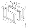
- FIG. 10 is an exploded perspective view of a module according to a sixth embodiment.
- FIG. 10 is a front view showing a positional relationship between a spacer and a prismatic secondary battery of a module according to a sixth embodiment.
- FIG. 10 is a front view showing a positional relationship between a spacer and a square secondary battery of a module according to a seventh embodiment.
- FIG. 10 is a front view showing a positional relationship between a spacer and a prismatic secondary battery of a module according to an eighth embodiment.
- FIG. 10 is a front view showing a positional relationship between a spacer of a module according to Embodiment 9 and a square secondary battery. The front view which shows the positional relationship of the spacer of the module which concerns on Example 10, and a square secondary battery.
- FIG. 1 is an external perspective view of a prismatic secondary battery 100 as an embodiment of a power storage element
- FIG. 2 is an exploded perspective view showing the configuration of the prismatic secondary battery 100
- FIG. 3 is a developed perspective view of the wound group 3 provided in the prismatic secondary battery 100.
- the rectangular secondary battery 100 includes a battery container 2 including a battery can 1 and a battery lid 6.
- the material of the battery can 1 and the battery lid 6 is aluminum or an aluminum alloy.
- the battery can 1 is formed in a rectangular parallelepiped flat box shape with one surface opened by subjecting a metal material to deep drawing.
- the battery can 1 includes a rectangular bottom surface 1d, a pair of wide side surfaces 1b adjacent to each of the pair of long sides of the bottom surface 1d, and a pair of narrow side surfaces 1c adjacent to each of the pair of short sides of the bottom surface 1d. have.
- the battery lid 6 has a rectangular flat plate shape, and closes the opening of the battery can 1 and is laser-welded. That is, the battery lid 6 seals the opening of the battery can 1.
- the battery cover 6 is electrically connected to the positive electrode terminal component 60 electrically connected to the positive electrode 34 (see FIG. 3) of the wound group 3, and the negative electrode 32 (see FIG. 3) of the wound group 3.
- the negative electrode side terminal structure part 70 connected in general is provided.
- the positive electrode side terminal component 60 includes a positive electrode bolt 14, a positive electrode connection terminal 62, a positive electrode external terminal 63, a positive electrode side external insulator 24, a gasket (not shown) disposed inside the battery can 1, and a positive electrode current collector 180. Consists of The positive electrode bolt 14, the positive electrode external terminal 63, the positive electrode connection terminal 62, the gasket and the positive electrode current collector 180 are integrally fixed and attached to the battery lid 6. In this state, the positive electrode current collector 180, the positive electrode connection terminal 62, and the positive electrode external terminal 63 are electrically connected. The positive electrode current collector 180, the positive electrode connection terminal 62, and the positive electrode external terminal 63 are insulated from the battery lid 6 by the positive electrode side external insulator 24 and the gasket.
- the negative electrode side terminal component 70 includes a negative electrode bolt 12, a negative electrode connection terminal 72, a negative electrode external terminal 73, a negative electrode side external insulator 22, a gasket (not shown) disposed inside the battery can 1, and a negative electrode current collector 190. Consists of The negative electrode side terminal component 70 has the same structure as the positive electrode side terminal component 60, and the negative electrode bolt 12, the negative electrode external terminal 73, the negative electrode connection terminal 72, and the negative electrode current collector 190 are integrally fixed, and the battery cover 6 is attached. In this state, the negative electrode current collector 190, the negative electrode connection terminal 72, and the negative electrode external terminal 73 are electrically connected. The negative electrode current collector 190, the negative electrode connection terminal 72, and the negative electrode external terminal 73 are insulated from the battery lid 6 by the negative electrode side external insulator 22 and the gasket.
- each of the positive and negative bolts 14 and 12 protrudes from the battery lid 6 and has a screw structure. Therefore, when producing an assembled battery, the positive electrode bolt 14 or the negative electrode bolt 12 is inserted into a bus bar (not shown) provided with holes or notches, and assembled with a nut. Thereby, the positive electrode external terminal 63 or the negative electrode external terminal 73 and the bus bar are electrically connected.
- the battery cover 6 is provided with a gas discharge valve 10.
- the gas discharge valve 10 is formed by partially thinning the battery cover 6 by press working.
- the thin film member may be attached to the opening of the battery lid 6 by laser welding or the like, and the thin portion of the thin film member may be used as a gas discharge valve.
- the gas discharge valve 10 generates heat when the square secondary battery 100 generates heat due to an abnormality such as overcharge, and when the pressure in the battery container rises and reaches a predetermined pressure, the gas discharge valve 10 is opened and gas is discharged from the inside. By discharging, the pressure in the battery container is reduced.
- the battery lid 6 is provided with a liquid injection hole (not shown) for injecting the electrolyte into the battery container.
- the liquid injection hole is sealed with a liquid injection stopper 11 after the electrolytic solution is injected.
- the electrolytic solution for example, a non-aqueous electrolytic solution in which a lithium salt such as lithium hexafluorophosphate (LiPF 6 ) is dissolved in a carbonate-based organic solvent such as ethylene carbonate can be used.
- the battery can 1 contains a wound electrode group 3 (hereinafter also referred to as a wound group) held by the lid assembly 107.
- the positive electrode current collector 180 bonded to the positive electrode 34 (see FIG. 3) of the winding group 3 and the negative electrode current collector 190 bonded to the negative electrode 32 (see FIG. 3) of the winding group 3 and the winding group 3 Is housed in the battery can 1 while being covered with the insulating case 108.
- the material of the insulating case 108 is an insulating resin such as polypropylene, and the battery can 1 and the wound group 3 are electrically insulated by the insulating case 108.
- the insulating case 108 includes an insulating case wide portion 108a that covers the wide side surface of the wound group 3, and two insulating case side surface portions 108b that cover the side surface portion of the wound group 3.
- the wide part 108a and the insulating case side part 108b may be integrated.
- the lid assembly 107 includes a positive electrode current collector 180, a positive electrode connection terminal 62, a positive electrode external terminal 63, a positive electrode bolt 14, a positive electrode side external insulator 24, a negative electrode current collector 190, a negative electrode connection terminal 72, a negative electrode external terminal 73, a negative electrode
- the bolt 12, the negative electrode side external insulator 22, the gasket and the battery lid 6 are assembled together.
- the positive electrode external terminal 63 is electrically connected to the positive electrode 34 (see FIG. 3) of the winding group 3 via the positive electrode current collector 180, and the negative electrode external terminal 73 is connected to the winding group 3 via the negative electrode current collector 190.
- the negative electrode 32 (see FIG. 3) is electrically connected. As a result, power is supplied from the wound group 3 to the external device via the positive external terminal 63 and the negative external terminal 73, or external generated power is supplied to the external group 3 via the positive external terminal 63 and the negative external terminal 73. To be charged.
- the positive electrode current collector 180 is made of aluminum or an aluminum alloy.
- the positive electrode current collector 180 includes a flat plate-shaped seat surface portion 181 attached along the lower surface of the battery lid 6 and a pair of flat surface portions 182 that are bent downward at approximately 90 ° at both ends in the width direction of the seat surface portion 181. And a flat joint plane portion 183 formed at the tip of each of the pair of plane portions 182.
- Each joining plane part 183 is joined to the winding group 3 by ultrasonic welding.
- Each of the bonding flat portions 183 is bent at an angle inclined with respect to the flat portion 182.
- the pair of joining flat portions 183 are inclined so as to be separated from each other in the short side direction of the battery cover 6 as they move from the central side in the long side direction of the battery cover 6 toward the outside, and the inclination directions are opposite to each other. Although it is a direction, it is the same angle with respect to the center plane and is line symmetric.
- the pair of joining plane portions 183 are inserted between the positive foil exposed portions 34b of the wound group 3 and the positive foil exposed portions 34b of the wound group 3 are opened in a V-shape. Joined by ultrasonic welding.
- the negative electrode current collector 190 is formed of copper or a copper alloy, but has the same structure as the positive electrode current collector 180.
- the negative electrode current collector 190 includes a flat seat surface portion 191 attached along the lower surface of the battery lid 6 and a pair of flat surface portions 192 that are bent downward at approximately 90 ° at both ends in the width direction of the seat surface portion 191. And a flat joint plane portion 193 formed at the tip of each of the pair of plane portions 192.
- Each joining plane part 193 is joined to the winding group 3 by ultrasonic welding.
- Each of the bonding plane portions 193 is bent at an angle inclined with respect to the plane portion 192.
- the pair of joining flat portions 192 are inclined so as to be separated from each other in the short side direction of the battery cover 6 as they move from the center side in the long side direction of the battery cover 6 toward the outside, and the inclination directions are opposite to each other. Although it is a direction, it is the same angle with respect to the center plane and is line symmetric.
- the pair of bonding flat portions 193 is inserted into the negative electrode foil exposed portion 32b with the negative foil exposed portion 32b of the wound group 3 inserted between them and the negative foil exposed portion 32b of the wound group 3 opened in a V shape. Joined by ultrasonic welding.
- FIG. 3 shows a state where the winding end side of the wound group 3 is developed.
- the winding group 3 which is a power generation element, has a laminated structure in which a long positive electrode 34 and a negative electrode 32 are wound in a flat shape around the winding center axis W with separators 33 and 35 interposed therebetween. ing.
- the positive electrode 34 has a positive electrode mixture layer 34a in which a positive electrode active material mixture is applied to both surfaces of a positive electrode foil that is a positive electrode current collector, and a positive electrode active material compound is formed at one end in the width direction of the positive electrode foil. There is provided a positive foil exposed portion 34b to which no agent is applied.
- the negative electrode 32 has a negative electrode mixture layer 32a in which a negative electrode active material mixture is applied to both surfaces of a negative electrode foil that is a negative electrode current collector, and the negative electrode active material mixture is formed at the other end in the width direction of the negative electrode foil.
- the negative electrode foil exposed part 32b which does not apply
- the positive electrode foil exposed portion 34b and the negative electrode foil exposed portion 32b are regions where the metal surface of the electrode foil is exposed, and are disposed at positions on one side and the other side in the winding central axis W direction (width direction in FIG. 3). To be wound up.
- negative electrode 32 10 parts by weight of polyvinylidene fluoride (hereinafter referred to as PVDF) is added as a binder to 100 parts by weight of amorphous carbon powder as a negative electrode active material, and N as a dispersion solvent.
- NMP kneading methylpyrrolidone
- amorphous carbon is used as the negative electrode active material, but the present invention is not limited to this.
- Natural graphite capable of inserting and removing lithium ions and various artificial graphite materials Carbonaceous materials such as coke, compounds such as Si and Sn (for example, SiO, TiSi2 etc.), or composite materials thereof may be used, and the particle shape is particularly limited, such as scaly, spherical, fibrous, or massive Is not to be done.
- the positive electrode 34 10 parts by weight of flaky graphite as a conductive material and 10 parts by weight of PVDF as a binder are added to 100 parts by weight of lithium manganate (chemical formula LiMn 2 O 4 ) as a positive electrode active material.
- a positive electrode mixture was prepared by adding and kneading NMP as a dispersion solvent. This positive electrode material mixture was applied to both surfaces of an aluminum foil (positive electrode foil) having a thickness of 20 ⁇ m, leaving the welded portion (positive electrode foil exposed portion 34b). Thereafter, a positive electrode 34 having a thickness of 90 ⁇ m in the thickness of the positive electrode active material coating portion not including an aluminum foil was obtained through drying, pressing, and cutting processes.
- lithium manganate is used as the positive electrode active material
- other lithium manganate having a spinel crystal structure or a lithium manganese composite oxide or layered in which a part is substituted or doped with a metal element A lithium cobalt oxide or lithium titanate having a crystal structure, or a lithium-metal composite oxide obtained by substituting or doping a part thereof with a metal element may be used.
- PVDF polytetrafluoroethylene
- PTFE polytetrafluoroethylene
- Polymers such as nitrile rubber, styrene butadiene rubber, polysulfide rubber, nitrocellulose, cyanoethyl cellulose, various latexes, acrylonitrile, vinyl fluoride, vinylidene fluoride, propylene fluoride, chloroprene fluoride, acrylic resins, and mixtures thereof Etc.
- One of the end portions of the winding group 3 in the width direction is a laminated portion of the positive electrode 34, and the other is a laminated portion of the negative electrode 32.
- the stacked portion of the positive electrode 34 provided at one end is formed by stacking the positive foil exposed portion 34b where the positive electrode mixture layer 34a is not formed.
- the laminated portion of the negative electrode 32 provided at the other end is obtained by laminating a negative foil exposed portion 32b where the negative electrode mixture layer 32a is not formed.
- the laminated portion of the positive electrode foil exposed portion 34b and the laminated portion of the negative electrode foil exposed portion 32b are respectively crushed in advance, and are ultrasonically bonded to the positive electrode current collector 180 and the negative electrode current collector 190 of the lid assembly 107 as described above. To form an electrode assembly.
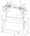
- FIG. 4 is a perspective view showing the module 200 of the present embodiment.
- the rectangular secondary battery 100 when the module 200 is manufactured will be described using an orthogonal coordinate system in which the thickness, width, and height directions are the X, Y, and Z directions, respectively.
- the module 200 includes a plurality of rectangular secondary batteries 100 stacked in the thickness direction (X direction), and a cell holder 91 that holds each rectangular secondary battery 100 in a stacked state.
- the cell holder 91 can be made of, for example, a resin material such as glass epoxy resin, polypropylene, or polybutylene terephthalate resin, or a metal material such as aluminum, copper, or stainless steel.
- the cell holder 91 includes a plurality of intermediate cell holders 92 and a pair of end cell holders 93.
- Intermediate cell holder 92 is interposed between prismatic secondary batteries 100 adjacent to each other.
- the end cell holders 93 are arranged at both ends in the stacking direction of the plurality of prismatic secondary batteries 100 held by the intermediate cell holder 92, and hold the prismatic secondary battery 100 between the intermediate cell holders 92.
- the end cell holder 93 has a shape in which the intermediate cell holder 92 is roughly divided into two parts parallel to the wide side surface 1 b of the prismatic secondary battery 100.
- the plurality of spacers 101, 102, 103 and the openings 111a, 111b provided in the intermediate cell holder 92 and the end cell holder 93 will be described later.
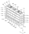
- FIG. 5 is a perspective view showing an assembled state of the pair of intermediate cell holders 92 and the prismatic secondary battery 100.
- FIG. 6 is a perspective view showing an exploded state of the pair of intermediate cell holders 92 and the prismatic secondary battery 100 shown in FIG.
- the intermediate cell holder 92 includes a pair of side plates 111, 111 facing the pair of narrow side surfaces 1 c, 1 c of the battery can 1 of the square secondary battery 100, and the bottom surface of the battery can 1. 1d and a bottom plate 112 facing each other.
- the intermediate cell holder 92 Since the intermediate cell holder 92 is disposed between the two rectangular secondary batteries 100, the intermediate cell holder 92 has a shape symmetrical to a plane passing through the middle of the two rectangular secondary batteries 100 and parallel to the wide side surface 1 b of the battery can 1. ing. Therefore, the side plate 111 and the bottom plate 112 of the intermediate cell holder 92 are respectively arranged in the thickness direction of the battery can 1 with respect to the narrow side surface 1c and the bottom surface 1d of the two rectangular secondary batteries 100 arranged on both sides of the intermediate cell holder 92. It is facing about half each.
- the pair of side plates 111, 111 are opposed to each other in the width direction (Y direction) of the wide side surface 1 b of the battery can 1, that is, both ends in the width direction of the rectangular secondary battery 100, and the stacking direction (X Direction), that is, extending in the thickness direction of the prismatic secondary battery 100.
- the bottom plate 112 extends in the stacking direction of the rectangular secondary battery 100 in the direction perpendicular to the bottom surface 1 d (Z direction) of the battery can 1, that is, the lower end in the height direction of the rectangular secondary battery 100, and has two side plates 111. The lower ends of the are connected.
- the two intermediate cell holders 92 and 92 disposed on both sides of the rectangular secondary battery 100 are held with the end portions of the side plates 111 and 111 and the bottom plates 112 and 112 being abutted or slightly spaced from each other. Thus, a space for holding the prismatic secondary battery 100 is formed between them.
- the pair of side plates 111, 111 are connected by a plurality of spacers 101, 102, 103. More specifically, the pair of side plates 111, 111 includes a lower end spacer 101 that connects these lower ends, an upper end spacer 102 that connects these upper ends, and an intermediate spacer 103 that connects these intermediate portions. It is connected by.
- the lower end spacer 101 is connected to the bottom plate 112 at the lower end.
- the upper end spacer 102 corresponds to the height of the portion from the battery lid 6 to the curved portion on the battery lid 6 side of the wound group 3 built in the battery can 1, and has a width in the Z direction as compared with other spacers. It is getting wider.
- the interval between the lower end spacer 101 and the intermediate spacer 103 and the interval between the upper end spacer 102 and the intermediate spacer 103 are smaller than the interval between the intermediate spacers 103.
- Each spacer 101, 102, 103 is disposed between two adjacent battery cans 1. That is, in the module 200, the square secondary battery 100 is laminated with the spacers 101, 102, and 103 interposed in the thickness direction.
- the side plate 111 has a first opening 111a and a second opening 111b.
- the first opening 111 a is formed at a position between the lower end spacer 101 and the intermediate spacer 103 and a position between the upper end spacer 102 and the intermediate spacer 103 in the Z direction.
- the second opening 111b is formed at a position between the intermediate spacers 103 in the Z direction.
- the first opening 111a and the second opening 111b have the same opening width in the X direction.
- the opening height in the Z direction of each opening is greater in the second opening 111b than in the first opening 111a, corresponding to the spacing between the spacers 101, 102, 103.
- the spacers 101, 102, and 103 are spaced apart from each other in the Z direction, and thereby a plurality of slits extending in the width direction (Y direction) along the wide side surface 1 b of the battery can 1 of the rectangular secondary battery 100. 114 and 115 are formed.
- the width in the Z direction is relatively small between the lower end spacer 101 and the intermediate spacer 103 and between the upper end spacer 102 and the intermediate spacer 103 corresponding to the distance between the spacers 101, 102, and 103.
- a narrow first slit 114 is formed.
- a second slit 115 having a relatively wide width in the Z direction is formed between the intermediate spacers 103.
- the first slit 114 communicates the first openings 111 a of the two side plates 111
- the second slit 115 communicates the second openings 111 b of the two side plates 111.
- a cooling medium is allowed to pass through the slits 114 and 115 so that the wide side surface 1b of the battery can 1 of the rectangular secondary battery 100 can be cooled.
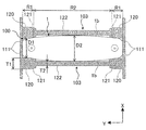
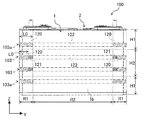
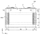
- FIG. 7 is a perspective view showing an assembled state of the pair of intermediate cell holders 92 and 92 and the prismatic secondary battery 100 shown in FIG. 5, and a cross section in which the intermediate cell holders 92 and 92 are cut along the XY plane so as to include the intermediate spacer 103.
- FIG. 7 is a perspective view showing an assembled state of the pair of intermediate cell holders 92 and 92 and the prismatic secondary battery 100 shown in FIG. 5, and a cross section in which the intermediate cell holders 92 and 92 are cut along the XY plane so as to include the intermediate spacer 103.
- the spacer 103 is divided into a plurality in the height direction (Z direction) of the wide side surface 1b of the battery can 1. Specifically, in the example shown in FIGS. 5 and 6, the spacer 103 is divided into four. As shown in FIG. 7, the spacer 103 includes a contact portion 120 that contacts the width direction end region R ⁇ b> 1 of the wide side surface 1 b of the battery can 1 constituting the battery case 2, and a width direction intermediate region R ⁇ b> 2 of the wide side surface 1 b. It has the opposing part 122 which opposes, and the inclined surface 121 adjacent to the both ends of the opposing part 122 in the width direction (Y direction) of the wide side surface 1b.
- the width direction end region R1 is a region having a predetermined width narrower than the width from the width direction end of the wide side surface 1b of the battery can 1 to the width direction center, and the width direction intermediate region R2 is The region between the width direction end region R1.
- the contact portions 120 are provided at both end portions of the spacer 103 in the width direction of the wide side surface 1b, and protrude toward the wide side surface 1b of the rectangular secondary battery 100 from the facing portion 122. That is, the thickness T1 of the contact portion 120 in the thickness direction (X direction) of the rectangular secondary battery 100 is greater than the thickness T2 of the facing portion 122 in the same direction. Thereby, in the pair of spacers 103 and 103 facing each other, the distance D1 between the contact parts 120 and 120 is narrower than the distance D2 between the facing parts 122 and 122. In other words, the distance D2 between the facing parts 122, 122 is wider than the distance D1 between the contact parts 120, 120. Further, the surfaces of the contact portion 120 and the facing portion 122 facing the wide side surface 1b of the battery can 1 are flat surfaces parallel to the width direction (Y direction) and the height direction (Z direction) of the rectangular secondary battery 100. Has been.
- the contact portions 120 are provided at both ends of each of the four spacers 103 and contact the width direction end region R1 of the wide side surface 1b of the battery can 1.
- the facing part 122 faces the intermediate region R2 in the width direction of the wide side surface 1b.
- an inclined surface 121 is provided inside the contact portion 120, and a facing portion 122 is provided inside the inclined surface 121.
- the inclined surface 121 abuts in the width direction (Y direction) of the wide side surface 1b at the position facing the entire height direction (Z direction) of the wide side surface 1b, that is, the height direction end region H1 and the intermediate region H2. It is provided between the portion 120 and the facing portion 122.
- the inclined surface 121 when the inclination angle of the inclined surface 121 with respect to the width direction (Y direction) of the wide side surface 1b of the battery can 1 is smaller than the inclination angle of the wide side surface 1b due to the expansion of the battery can 1, the inclined surface 121 is changed to the wide side surface. In addition to suppressing the expansion of the wide side surface 1b, the stress acting on the wide side surface 1b can be reduced as compared with the case where the inclined surface 121 is not formed. Further, if the inclination angle of the inclined surface 121 is approximately the same as the inclination angle of the wide side surface 1b of the battery can 1, the entire inclined surface 121 is substantially brought into contact with the wide side surface 1b and acts on the wide side surface 1b. The stress can be further reduced.
- the inclination angle of the inclined surface 121 is larger than the inclination angle of the wide side surface 1b, the contact between the spacer 103 and the wide side surface 1b is avoided between the contact portion 120 and the facing portion 122, and the inclined surface Stress concentration is prevented from occurring between 121 and the wide side surface 1 b of the battery can 1.
- the distance D ⁇ b> 2 between the pair of facing portions 122, 122 is such that when the battery can 1 is expanded such that the battery performance of the prismatic secondary battery 100 is deteriorated, the facing portion 122 has the wide side surface of the battery can 1. It is set to abut against 1b and suppress the expansion of the battery can 1. Therefore, when the battery can 1 does not expand so as to adversely affect the battery performance, the facing portion 122 does not contact the wide side surface 1b of the battery can 1.
- the width direction end region R1 of the wide side surface 1b of the battery can 1 that constitutes the battery container 2 of the prismatic secondary battery 100. Can be securely held between the contact portions 120, 120 of the spacers 103, 103, and the positioning accuracy of the prismatic secondary battery 100 can be improved. Further, while the stress concentration on the wide side surface 1b is suppressed by the inclined surface 121, the expansion of the battery case 2 can be suppressed by the facing portion 122 that faces the intermediate region R2 in the width direction of the wide side surface 1b.
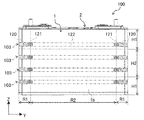
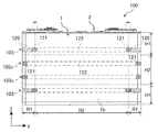
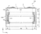
- FIG. 9 is a front view showing the positional relationship between the prismatic secondary battery 100 and the intermediate spacers 103 and 103a of the prismatic secondary battery module, which is the assembled battery of the present embodiment, corresponding to FIG. 8 of the first embodiment. .
- the module of the present embodiment is different from the intermediate portion spacer 103 of the first embodiment described above in the configuration of the intermediate portion spacer 103a included in the intermediate portion cell holder 92 and the end portion cell holder 93 constituting the cell holder 91. Since the other points of the module of the present embodiment are the same as those of the module 200 of the first embodiment, the same portions are denoted by the same reference numerals and description thereof is omitted.
- the two spacers 103 and 103 facing the height direction intermediate region H2 of the wide side surface 1b of the battery can 1 have the same configuration as the spacer 103 of the first embodiment.
- the two spacers 103a and 103a facing the height direction end regions H1 and H1 of the wide side surface 1b of the battery can 1 are different from the spacer 103 of the first embodiment in that the inclined surface 121 is not formed. ing.
- the inclined surface 121 provided on the spacers 103 and 103 is a position facing the intermediate region H2 in the height direction of the wide side surface 1b of the battery can 1, and the width direction (Y direction) of the wide side surface 1b. 1 is provided between the contact portion 120 and the facing portion 122.
- the length L0 of the contact portion 120 in the width direction of the wide side surface 1b of the spacer 103a facing the height direction end region H1 of the wide side surface 1b is the same direction of the contact portion 120 of the spacer 103 therebetween. Longer than L0. That is, the length L0 of the contact portion 120 along the width direction of the wide side surface 1b is gradually increased in the direction from the height direction intermediate region H2 to the height direction end region H1.
- the thickness of the battery can 1 when the battery can 1 expands is greatest at the center in the height direction (Z direction) and the width direction (Y direction) of the wide side surface 1b of the battery can 1, and at the end in each direction. It gets smaller as you go. Therefore, stress concentration may not occur in the battery can 1 even if the inclined surface 121 is not formed in the spacer 103a facing the height direction end region H1 as in the module of the present embodiment.
- the module 200 of the first embodiment includes the spacer 103 having the same configuration as that of the first embodiment facing the intermediate region in the height direction of the wide side surface 1b of the battery can 1. Similar effects can be obtained.
- the length L0 of the contact portion 120 along the width direction of the wide side surface 1b is gradually increased in the direction from the intermediate region H2 in the height direction toward the end region H1 in the height direction.
- the width direction end region R1 of the wide side surface 1b can be more reliably held by the relatively long contact portion 120 of the spacer 103a.
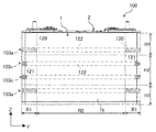
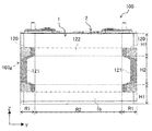
- FIG. 10 is a front view showing the positional relationship between the prismatic secondary battery 100 and the intermediate spacers 103 and 103b of the prismatic secondary battery module, which is the assembled battery of the present embodiment, corresponding to FIG. 8 of the first embodiment. .
- the length L0 in the same direction of the contact portion 120 of the spacer 103 facing the height direction end region H1 is the length in the same direction of the contact portion 120 of the spacer 103b facing the intermediate region H2 in the height direction. Longer than L0. That is, the length L0 of the contact portion 120 along the width direction of the wide side surface 1b of the battery can 1 is gradually increased in the direction from the height direction intermediate region H2 to the height direction end region H1. Since the other points of the module of the present embodiment are the same as those of the module 200 of the first embodiment, the same portions are denoted by the same reference numerals and description thereof is omitted.
- the thickness of the battery can 1 when the battery can 1 expands is the largest in the height direction and the center in the width direction of the wide side surface 1b of the battery can 1, and the thickness decreases toward the end in each direction.
- the module of the present embodiment not only the same effects as the module 200 of the first embodiment described above can be obtained, but also the length L0 of the contact portion 120 is increased from the height direction intermediate region H2 of the wide side surface 1b.
- the width direction end region R1 can be more reliably held by the relatively long contact portion 120 in the height direction end region H1 of the battery can 1. it can.
- the length L2 of the facing portion 122 along the width direction of the wide side surface 1b of the battery can 1 is gradually increased in the direction from the height direction end region H1 to the height direction intermediate region H2.
- the position of the contact portion 120 is close to both end portions of the spacer 103b. Therefore, in the height direction intermediate region H2, the stress concentration in the width direction end region R1 of the wide side surface 1b of the battery can 1 can be further relaxed.
- FIG. 11 is a front view showing the positional relationship between the prismatic secondary battery 100 and the intermediate spacers 103 and 103c of the prismatic secondary battery module, which is the assembled battery of the present embodiment, corresponding to FIG. 8 of the first embodiment. .
- the inclined surface 121 is provided between the contact portion 120 and the facing portion 122 in the width direction of the wide side surface 1b.
- the inclined surfaces 121 are provided at both ends in the width direction of the wide side surface 1b of the battery can 1. Since the other points of the module of the present embodiment are the same as those of the module 200 of the first embodiment, the same portions are denoted by the same reference numerals and description thereof is omitted.
- the thickness of the battery can 1 when the battery can 1 expands is the largest in the height direction and the center in the width direction of the wide side surface 1b of the battery can 1, and the thickness decreases toward the end in each direction.
- the spacer 103 having the same configuration as that of the first embodiment is provided at a position facing the height direction end region H1 of the wide side surface 1b of the battery can 1, and the spacer 103c facing the height direction intermediate region H2 is in contact.
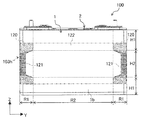
- FIG. 12 is a front view showing the positional relationship between the prismatic secondary battery 100 and the intermediate spacers 103a and 103c of the prismatic secondary battery module, which is the assembled battery of the present embodiment, corresponding to FIG. 8 of the first embodiment. .
- the spacer 103a facing the height direction end region H1 of the wide side surface 1b of the battery can 1 has the same configuration as the spacer 103a of the above-described second embodiment, and the height of the wide side surface 1b.
- the spacer 103c facing the vertical intermediate region H2 has the same configuration as the spacer 103c of the fourth embodiment described above.
- the spacer 103a at a position facing the height direction end region H1 has the contact portion 120 and the facing portion 122 and does not have the inclined surface 121.
- the spacer 103c at a position facing the intermediate region H2 in the height direction has the inclined surface 121 and the facing portion 122, and does not have the contact portion 120. Since the other points of the module of the present embodiment are the same as those of the module 200 of the first embodiment, the same portions are denoted by the same reference numerals and description thereof is omitted.
- the thickness of the battery can 1 when the battery can 1 expands is the largest in the height direction and the center in the width direction of the wide side surface 1b of the battery can 1, and the thickness decreases toward the end in each direction.
- the spacer 130a at the position facing the height direction end region H1 of the wide side surface 1b of the battery can 1 has the same configuration as the spacer 130a of the second embodiment, and the middle in the height direction. Since the spacer 103c at the position facing the region H2 has the same configuration as the spacer 103c of the fourth embodiment, not only can the same effect as the module 200 of the first embodiment be obtained, but also the modules of the second and fourth embodiments. Similar effects can be obtained.
- the intermediate spacer 103d of the module of the present embodiment is integrally provided in the height direction (Z direction) of the rectangular secondary battery 100, the lower end is connected to the lower end spacer 101, and the upper end is connected to the upper end spacer 102.
- the intermediate cell holder 92 and the end cell holder 93 include notches 112 a for cooling the square secondary battery 100 on the bottom plate 112 in place of the openings 111 a and 111 b and the slits 114 and 115 of the side plate 111. Yes.
- the notch 112a exposes the bottom surface 1d of the battery can 1 from the bottom plate 112 of the cell holders 92 and 93 when the prismatic secondary battery 100 is assembled into the cell holder 91, thereby allowing the prismatic secondary battery 100 to be cooled. Yes. Since the other points of the module of the present embodiment are the same as those of the module 200 of the first embodiment, the same portions are denoted by the same reference numerals and description thereof is omitted.
- the spacer 103d of this embodiment has the same configuration as the spacer 103 of Embodiment 1 shown in FIGS. 7 and 8 except that the spacer 103d is integrally provided in the height direction of the prismatic secondary battery 100.
- the spacer 103d includes an abutment portion 120 that abuts on the width direction end region R1 of the wide side surface 1b of the battery can 1, an opposing portion 122 that opposes the width direction intermediate region R2 of the wide side surface 1b, and the battery can 1. It has the inclined surface 121 adjacent to the both ends of the opposing part 122 in the width direction of the wide side surface 1b.
- the inclined surface 121 is inclined so that the thickness of the spacer 103d decreases in the direction from the width direction end region R1 toward the width direction intermediate region R2. Thereby, the inclined surface 121 inclines along the wide side surface 1b of the battery can 1 which expanded in the convex curved surface shape where the thickness of the center part becomes the thickest. Therefore, when the wide side surface 1b of the expanded battery can 1 is pressed by the contact portion 120 or the facing portion 122 of the spacer 103d, it is possible to prevent stress concentration from occurring on the wide side surface 1b of the battery can 1 due to the spacer 103. Therefore, it is possible to improve both the reliability of the battery can 1 and suppress the deterioration of battery performance.
- the width direction end region R1 of the wide side surface 1b of the battery can 1 constituting the battery container 2 of the prismatic secondary battery 100 is the spacer 103d. , 103d can be securely held between the contact portions 120, 120, and the positioning accuracy of the rectangular secondary battery 100 can be improved. Further, while the stress concentration on the wide side surface 1b is suppressed by the inclined surface 121, the expansion of the battery case 2 can be suppressed by the facing portion 122 that faces the intermediate region R2 in the width direction of the wide side surface 1b.
- the wide side surface 1b of the battery can 1 is pressed by the spacer 103d having a large area integrally formed as compared with the spacer 103 of the first embodiment divided into a plurality of parts, the battery can 1 can be more reliably attached. Expansion of the wide side surface 1b can be suppressed, and deterioration of battery performance can be suppressed more reliably.
- the intermediate spacer 103e is integrally provided in the height direction of the rectangular secondary battery 100, the same effect as that of the intermediate spacer 103d of Embodiment 6 can be obtained.
- the spacer of the second embodiment Similarly to 103a, in the height direction end region H1 of the wide side surface 1b of the battery can 1, the width direction end region R1 can be more reliably held by the contact portion 120 of the spacer 103a.
- FIG. 17 is a front view showing the positional relationship between the prismatic secondary battery 100 and the intermediate spacer 103g of the module of the present embodiment, which corresponds to FIG. 8 of the first embodiment.
- the intermediate spacer 103g is integrally provided in the height direction of the square secondary battery 100, the same effect as that of the module of the sixth embodiment can be obtained.
- the inclined surface 121 is provided between the contact portion 120 and the facing portion 122 at a position facing the height direction end region H1 of the wide side surface 1b, and at a position facing the height direction intermediate region H2. Since it is provided at both ends in the width direction, the same effect as the module of the fourth embodiment can be obtained.
- the intermediate spacer 103h has an abutting portion 120 and an opposing portion 122 at a position facing the height direction end region H1, and is inclined. There is no surface 121.
- the intermediate spacer 103h has an inclined surface 121 and an opposing portion 122 at a position facing the intermediate region H2 in the height direction. I don't have it.
- Battery can (battery container) 1b Wide side surface 2 Battery container 3 Winding group (electrode group) 6 Battery cover (battery container) 32 Negative electrode 34 Positive electrode 100 Square secondary battery 103 Spacer 120 Abutting portion 121 Inclined surface 122 Opposing portion 200 Module (assembled battery) L0 Length of contact portion L2 Length of opposite portion R1 Width direction end region R2 Width direction intermediate region H1 Height direction end region H2 Height direction intermediate region X Thickness direction Y Width direction Z Height direction
Abstract
Provided is an assembled cell by which it is possible to reliably hold rectangular secondary cells in place and to improve positioning accuracy, and by which it is possible to minimize expansion of a cell container while preventing concentration of stress on the cell container. The assembled cell is formed by stacking a plurality of rectangular secondary cells (100) in the thickness direction interposed by spacers (103), the rectangular secondary cells (100) housing therein a group of electrodes formed by coiling positive and negative electrodes inside a flat box-shaped cell container (2). The spacers (103) have abutting portions (120) that abut the widthwise direction terminal regions (R1) of the wide side faces (1b) of the cell container (2), facing portions (122) that face the widthwise intermediate region (R2) of the wide side faces (1b), and inclined surfaces (121) adjacent to both ends of the facing portions (122) in the widthwise direction (Y direction) of the wide side faces (1b), the inclined surfaces (121) being inclined such that the thickness (T1) of the spacers (103) decreases from the widthwise terminal regions (R1) towards the widthwise intermediate region (R2).
Description
本発明は、例えばスペーサを介在させて複数の角形二次電池を積層させた組電池に関する。
The present invention relates to an assembled battery in which a plurality of rectangular secondary batteries are stacked with a spacer interposed therebetween, for example.
従来、再充電可能な二次電池の分野では、鉛電池、ニッケル-カドミウム電池、ニッケル-水素電池等の水溶液系電池が主流であった。しかしながら、電気機器の小型化、軽量化が進むにつれ、高いエネルギー密度を有するリチウムイオン二次電池が着目され、その研究、開発及び商品化が急速に進められている。
Conventionally, in the field of rechargeable secondary batteries, aqueous batteries such as lead batteries, nickel-cadmium batteries and nickel-hydrogen batteries have been mainstream. However, as electric appliances become smaller and lighter, lithium ion secondary batteries having a high energy density have attracted attention, and their research, development, and commercialization are rapidly progressing.
また、地球温暖化や枯渇燃料の観点から、電気自動車(EV)や駆動の一部を電気モータで補助するハイブリッド電気自動車(HEV)が各自動車メーカーで開発され、その電源として高容量で高出力の二次電池が求められるようになってきた。このような要求に合致する電源として、高電圧の非水溶液系のリチウムイオン二次電池が注目されている。特に角形リチウムイオン二次電池はパック化した際の体積効率が優れているため、HEVまたはEV用として角形リチウムイオン二次電池の開発への期待が高まっている。
In addition, from the perspective of global warming and depleted fuel, electric vehicles (EV) and hybrid electric vehicles (HEV) that use electric motors to assist a part of the drive have been developed by each automobile manufacturer. Secondary batteries have come to be demanded. As a power source that meets such requirements, high-voltage non-aqueous lithium ion secondary batteries have attracted attention. In particular, prismatic lithium ion secondary batteries have excellent volumetric efficiency when packed into packs, and therefore, there is an increasing expectation for the development of prismatic lithium ion secondary batteries for HEVs or EVs.
HEVまたはEV用などの大電流用途では、電池の発熱は避けられず、電池の冷却が必要となる。一般的には、複数の電池を直列およびまたは並列に電気的に接続して構成される組電池の各電池間に隙間を設け、その隙間に空気などの冷却媒体を流すことで電池の冷却を行っている。また、組電池を構成する個々の電池は、電池容器内に収容されている電極材料が充電に伴って膨張することで、電池容器が膨張することがある。
In high current applications such as for HEV or EV, heat generation of the battery is inevitable and the battery needs to be cooled. Generally, a gap is provided between each battery of an assembled battery configured by electrically connecting a plurality of batteries in series and / or in parallel, and cooling of the battery is performed by flowing a cooling medium such as air through the gap. Is going. Moreover, as for each battery which comprises an assembled battery, an electrode material accommodated in a battery container may expand | swell with charge, and a battery container may expand | swell.
電池容器の膨張を抑制することができる組電池として、各二次電池の外面のうち最大面積の側面(被圧迫面)が部分的に圧迫された状態で、二次電池が拘束されている二次電池アセンブリが開示されている(下記特許文献1参照)。
As an assembled battery capable of suppressing the expansion of the battery container, the secondary battery is restrained in a state in which the side surface (pressed surface) of the maximum area among the outer surfaces of each secondary battery is partially compressed. A secondary battery assembly is disclosed (see Patent Document 1 below).
特許文献1に記載の二次電池アセンブリは、大電流の充放電を繰り返すハイレートで使用される二次電池において、被圧迫面の面圧を均一に保持して二次電池の劣化を抑制することを課題とし、その解決手段として接触部材と拘束部材とを有している。接触部材は、被圧迫面に接触する、離散的に設けられた複数の接触部を有している。接触部は、被圧迫面に向かって連結部から突出して形成されており、捲回状の電極体における捲回軸方向の中央寄りの部位に対応する、両方の片寄り領域の間の中央領域にて被圧迫面をより弱く圧迫する形状または配置そのものとされている。具体的には、接触部材は、被圧迫面に接触する頂面が中央で凹となるように湾曲し、被圧迫面への圧迫力をその面内の箇所によって異ならせることが記載されている。一方で、接触部材は、単電池のケースの端部に接触せず、ケースの端部を圧迫しないように、各部材の配置が決定されることが記載されている。
The secondary battery assembly described in Patent Document 1 suppresses deterioration of the secondary battery by uniformly maintaining the surface pressure of the pressed surface in a secondary battery used at a high rate that repeatedly charges and discharges a large current. And has a contact member and a restraining member as means for solving the problem. The contact member has a plurality of discrete contact portions that contact the pressed surface. The contact portion is formed so as to protrude from the connecting portion toward the pressed surface, and corresponds to a central portion in the winding axis direction of the wound electrode body, and a central region between both offset regions The shape or arrangement itself presses the surface to be pressed more weakly. Specifically, it is described that the contact member is curved so that the top surface contacting the surface to be compressed is concave in the center, and the compression force to the surface to be compressed varies depending on the location in the surface. . On the other hand, it is described that the arrangement of each member is determined so that the contact member does not contact the end portion of the unit cell case and does not press the end portion of the case.
特許文献1に記載の二次電池アセンブリでは、接触部材が単電池の被圧迫面を圧迫することで被圧迫面の膨張が抑制されるが、単電池のケースの端部が固定されていないため、車載時の振動等により単電池が移動しやすくなるなど、単電池の位置決めに課題がある。一方で、単電池のケースの端部に圧力を加えて端部を保持した場合、ケースに応力集中が発生する虞がある。
In the secondary battery assembly described in Patent Document 1, expansion of the pressed surface is suppressed by the contact member pressing the pressed surface of the unit cell, but the end of the case of the unit cell is not fixed. However, there is a problem in positioning of the unit cell such that the unit cell can be easily moved by vibration when mounted on the vehicle. On the other hand, when pressure is applied to the end portion of the cell case to hold the end portion, stress concentration may occur in the case.
本発明は、前記課題に鑑みてなされたものであり、角形二次電池を確実に保持して位置決め精度を向上させると共に、電池容器に応力集中が生じることを防止しつつ、電池容器の膨張を抑制することができる組電池を提供することを目的とする。
The present invention has been made in view of the problems described above, and is capable of improving the positioning accuracy by reliably holding the square secondary battery, and preventing the battery container from being concentrated while expanding the battery container. It aims at providing the assembled battery which can be suppressed.
前記目的を達成すべく、本発明の組電池は、扁平箱型の電池容器内に正負の電極を捲回した電極群が収容配置された複数の角形二次電池を、厚さ方向にスペーサを介在させて積層させた組電池であって、前記スペーサは、前記電池容器の幅広側面の幅方向端部領域に当接する当接部と、前記幅広側面の幅方向中間領域に対向する対向部と、前記幅広側面の幅方向において前記対向部の両端に隣接する傾斜面とを有し、前記傾斜面は、前記幅方向端部領域から前記幅方向中間領域に向かう方向において、前記スペーサの厚みが減少するように傾斜していることを特徴とする。
In order to achieve the above object, the assembled battery of the present invention comprises a plurality of rectangular secondary batteries in which a group of electrodes in which positive and negative electrodes are wound and accommodated in a flat box type battery container, and spacers in the thickness direction. The battery assembly is an assembled battery, wherein the spacer includes an abutting portion that contacts an end region in the width direction of the wide side surface of the battery container, and an opposing portion that faces an intermediate region in the width direction of the wide side surface. And an inclined surface adjacent to both ends of the facing portion in the width direction of the wide side surface, and the inclined surface has a thickness of the spacer in the direction from the width direction end region toward the width direction intermediate region. It is inclined so as to decrease.
本発明の組電池によれば、角形二次電池の電池容器の幅広側面の幅方向端部領域をスペーサの当接部間で確実に保持して位置決め精度を向上させると共に、スペーサの傾斜面によって電池容器に応力集中が生じることを防止しつつ、該幅広側面の幅方向中間領域に対向する対向部によって電池容器の膨張を抑制することができる。
According to the assembled battery of the present invention, the width direction end region of the wide side surface of the battery container of the square secondary battery is securely held between the contact portions of the spacer to improve positioning accuracy, and the inclined surface of the spacer While preventing stress concentration in the battery container, expansion of the battery container can be suppressed by the facing portion that faces the intermediate region in the width direction of the wide side surface.
以下、図面を参照して本発明の組電池である角形二次電池モジュールの実施形態について説明する。
Hereinafter, embodiments of a rectangular secondary battery module which is an assembled battery of the present invention will be described with reference to the drawings.
[実施形態1]
(角形二次電池)
まず、本実施形態の角形二次電池モジュールが備える角形二次電池について説明する。図1は蓄電素子の一実施の形態としての角形二次電池100の外観斜視図であり、図2は角形二次電池100の構成を示す分解斜視図である。図3は、角形二次電池100が備える捲回群3の展開斜視図である。 [Embodiment 1]
(Square secondary battery)
First, the prismatic secondary battery provided in the prismatic secondary battery module of the present embodiment will be described. FIG. 1 is an external perspective view of a prismaticsecondary battery 100 as an embodiment of a power storage element, and FIG. 2 is an exploded perspective view showing the configuration of the prismatic secondary battery 100. FIG. 3 is a developed perspective view of the wound group 3 provided in the prismatic secondary battery 100.
(角形二次電池)
まず、本実施形態の角形二次電池モジュールが備える角形二次電池について説明する。図1は蓄電素子の一実施の形態としての角形二次電池100の外観斜視図であり、図2は角形二次電池100の構成を示す分解斜視図である。図3は、角形二次電池100が備える捲回群3の展開斜視図である。 [Embodiment 1]
(Square secondary battery)
First, the prismatic secondary battery provided in the prismatic secondary battery module of the present embodiment will be described. FIG. 1 is an external perspective view of a prismatic
図1に示すように、角形二次電池100は、電池缶1と電池蓋6とからなる電池容器2を備えている。電池缶1および電池蓋6の材質は、アルミニウムまたはアルミニウム合金などである。電池缶1は、金属材料に深絞り加工を施すことによって、一面が開口された直方体形状の扁平箱型に形成されている。電池缶1は、長方形状の底面1dと、底面1dの一対の長辺のそれぞれに隣接する一対の幅広側面1bと、底面1dの一対の短辺のそれぞれに隣接する一対の幅狭側面1cとを有している。
As shown in FIG. 1, the rectangular secondary battery 100 includes a battery container 2 including a battery can 1 and a battery lid 6. The material of the battery can 1 and the battery lid 6 is aluminum or an aluminum alloy. The battery can 1 is formed in a rectangular parallelepiped flat box shape with one surface opened by subjecting a metal material to deep drawing. The battery can 1 includes a rectangular bottom surface 1d, a pair of wide side surfaces 1b adjacent to each of the pair of long sides of the bottom surface 1d, and a pair of narrow side surfaces 1c adjacent to each of the pair of short sides of the bottom surface 1d. have.
電池蓋6は、矩形平板状であって、電池缶1の開口を塞いでレーザ溶接されている。つまり、電池蓋6は、電池缶1の開口を封止している。また、電池蓋6は、捲回群3の正極電極34(図3参照)と電気的に接続された正極側端子構成部60と、捲回群3の負極電極32(図3参照)と電気的に接続された負極側端子構成部70を備えている。
The battery lid 6 has a rectangular flat plate shape, and closes the opening of the battery can 1 and is laser-welded. That is, the battery lid 6 seals the opening of the battery can 1. In addition, the battery cover 6 is electrically connected to the positive electrode terminal component 60 electrically connected to the positive electrode 34 (see FIG. 3) of the wound group 3, and the negative electrode 32 (see FIG. 3) of the wound group 3. The negative electrode side terminal structure part 70 connected in general is provided.
正極側端子構成部60は、正極ボルト14、正極接続端子62、正極外部端子63、正極側外部絶縁体24および電池缶1の内部に配置されるガスケット(図示せず)、正極集電体180から構成される。正極ボルト14、正極外部端子63、正極接続端子62、ガスケットおよび正極集電体180は、一体的に固定され、電池蓋6に取り付けられている。この状態において、正極集電体180、正極接続端子62、正極外部端子63は、電気的に接続されている。また、正極集電体180、正極接続端子62、正極外部端子63は、正極側外部絶縁体24およびガスケットにより電池蓋6から絶縁されている。
The positive electrode side terminal component 60 includes a positive electrode bolt 14, a positive electrode connection terminal 62, a positive electrode external terminal 63, a positive electrode side external insulator 24, a gasket (not shown) disposed inside the battery can 1, and a positive electrode current collector 180. Consists of The positive electrode bolt 14, the positive electrode external terminal 63, the positive electrode connection terminal 62, the gasket and the positive electrode current collector 180 are integrally fixed and attached to the battery lid 6. In this state, the positive electrode current collector 180, the positive electrode connection terminal 62, and the positive electrode external terminal 63 are electrically connected. The positive electrode current collector 180, the positive electrode connection terminal 62, and the positive electrode external terminal 63 are insulated from the battery lid 6 by the positive electrode side external insulator 24 and the gasket.
負極側端子構成部70は、負極ボルト12、負極接続端子72、負極外部端子73、負極側外部絶縁体22および電池缶1の内部に配置されるガスケット(図示せず)、負極集電体190から構成される。負極側端子構成部70は、正極側端子構成部60と同様な構造であり、負極ボルト12、負極外部端子73、負極接続端子72および負極集電体190は、一体的に固定され、電池蓋6に取り付けられている。この状態において、負極集電体190、負極接続端子72、負極外部端子73は、電気的に接続されている。また、負極集電体190、負極接続端子72、負極外部端子73は、負極側外部絶縁体22およびガスケットにより電池蓋6から絶縁されている。
The negative electrode side terminal component 70 includes a negative electrode bolt 12, a negative electrode connection terminal 72, a negative electrode external terminal 73, a negative electrode side external insulator 22, a gasket (not shown) disposed inside the battery can 1, and a negative electrode current collector 190. Consists of The negative electrode side terminal component 70 has the same structure as the positive electrode side terminal component 60, and the negative electrode bolt 12, the negative electrode external terminal 73, the negative electrode connection terminal 72, and the negative electrode current collector 190 are integrally fixed, and the battery cover 6 is attached. In this state, the negative electrode current collector 190, the negative electrode connection terminal 72, and the negative electrode external terminal 73 are electrically connected. The negative electrode current collector 190, the negative electrode connection terminal 72, and the negative electrode external terminal 73 are insulated from the battery lid 6 by the negative electrode side external insulator 22 and the gasket.
なお、正極ボルト14及び負極ボルト12は、それぞれ電池蓋6の外部に突出しており、さらにねじ構造を有している。そのため組電池を作成する場合には、穴または切り欠きが設けられたバスバー(図示せず)に正極ボルト14又は負極ボルト12を挿通させ、ナットで組みつける構造となる。これにより、正極外部端子63または負極外部端子73とバスバーが電気的に接続される。
Note that each of the positive and negative bolts 14 and 12 protrudes from the battery lid 6 and has a screw structure. Therefore, when producing an assembled battery, the positive electrode bolt 14 or the negative electrode bolt 12 is inserted into a bus bar (not shown) provided with holes or notches, and assembled with a nut. Thereby, the positive electrode external terminal 63 or the negative electrode external terminal 73 and the bus bar are electrically connected.
また、電池蓋6には、ガス排出弁10が設けられている。ガス排出弁10は、プレス加工によって電池蓋6を部分的に薄肉化することで形成されている。なお、薄膜部材を電池蓋6の開口にレーザ溶接等により取り付けて、薄膜部材の薄肉部分をガス排出弁としてもよい。ガス排出弁10は、角形二次電池100が過充電等の異常により発熱してガスが発生し、電池容器内の圧力が上昇して所定圧力に達したときに開裂して、内部からガスを排出することで電池容器内の圧力を低減させる。
The battery cover 6 is provided with a gas discharge valve 10. The gas discharge valve 10 is formed by partially thinning the battery cover 6 by press working. The thin film member may be attached to the opening of the battery lid 6 by laser welding or the like, and the thin portion of the thin film member may be used as a gas discharge valve. The gas discharge valve 10 generates heat when the square secondary battery 100 generates heat due to an abnormality such as overcharge, and when the pressure in the battery container rises and reaches a predetermined pressure, the gas discharge valve 10 is opened and gas is discharged from the inside. By discharging, the pressure in the battery container is reduced.
さらに、電池蓋6には、電池容器内に電解液を注入するための注液孔(不図示)が穿設されている。注液孔は、電解液注入後に注液栓11によって封止される。電解液としては、たとえば、エチレンカーボネート等の炭酸エステル系の有機溶媒に6フッ化リン酸リチウム(LiPF6)等のリチウム塩が溶解された非水電解液を用いることができる。
Further, the battery lid 6 is provided with a liquid injection hole (not shown) for injecting the electrolyte into the battery container. The liquid injection hole is sealed with a liquid injection stopper 11 after the electrolytic solution is injected. As the electrolytic solution, for example, a non-aqueous electrolytic solution in which a lithium salt such as lithium hexafluorophosphate (LiPF 6 ) is dissolved in a carbonate-based organic solvent such as ethylene carbonate can be used.
次に、電池缶1の内部構造について説明する。図2に示すように、電池缶1には蓋組立体107に保持された捲回電極群3(以下、捲回群ともいう。)が収容されている。捲回群3の正極電極34(図3参照)に接合される正極集電体180および捲回群3の負極電極32(図3参照)に接合される負極集電体190ならびに捲回群3は、絶縁ケース108に覆われた状態で電池缶1に収容されている。
Next, the internal structure of the battery can 1 will be described. As shown in FIG. 2, the battery can 1 contains a wound electrode group 3 (hereinafter also referred to as a wound group) held by the lid assembly 107. The positive electrode current collector 180 bonded to the positive electrode 34 (see FIG. 3) of the winding group 3 and the negative electrode current collector 190 bonded to the negative electrode 32 (see FIG. 3) of the winding group 3 and the winding group 3 Is housed in the battery can 1 while being covered with the insulating case 108.
絶縁ケース108の材質は、ポリプロピレン等の絶縁性を有する樹脂であり、電池缶1と、捲回群3とは絶縁ケース108によって電気的に絶縁されている。なお、本実施形態では絶縁ケース108は捲回群3の幅広側面を覆う絶縁ケース幅広部108aと、捲回群3の側面部を覆う2つの絶縁ケース側面部108bから構成されるが、絶縁ケース幅広部108aと絶縁ケース側面部108bを一体とする構造であっても良い。
The material of the insulating case 108 is an insulating resin such as polypropylene, and the battery can 1 and the wound group 3 are electrically insulated by the insulating case 108. In this embodiment, the insulating case 108 includes an insulating case wide portion 108a that covers the wide side surface of the wound group 3, and two insulating case side surface portions 108b that cover the side surface portion of the wound group 3. The wide part 108a and the insulating case side part 108b may be integrated.
蓋組立体107は、正極集電体180、正極接続端子62、正極外部端子63、正極ボルト14、正極側外部絶縁体24、負極集電体190、負極接続端子72、負極外部端子73、負極ボルト12、負極側外部絶縁体22、ガスケット及び電池蓋6を一体に組み立てたものである。
The lid assembly 107 includes a positive electrode current collector 180, a positive electrode connection terminal 62, a positive electrode external terminal 63, a positive electrode bolt 14, a positive electrode side external insulator 24, a negative electrode current collector 190, a negative electrode connection terminal 72, a negative electrode external terminal 73, a negative electrode The bolt 12, the negative electrode side external insulator 22, the gasket and the battery lid 6 are assembled together.
正極外部端子63は正極集電体180を介して捲回群3の正極電極34(図3参照)に電気的に接続され、負極外部端子73は負極集電体190を介して捲回群3の負極電極32(図3参照)に電気的に接続されている。これにより、正極外部端子63および負極外部端子73を介して捲回群3から外部機器に電力が供給され、あるいは、正極外部端子63および負極外部端子73を介して外部発電電力が捲回群3に供給されて充電される。
The positive electrode external terminal 63 is electrically connected to the positive electrode 34 (see FIG. 3) of the winding group 3 via the positive electrode current collector 180, and the negative electrode external terminal 73 is connected to the winding group 3 via the negative electrode current collector 190. The negative electrode 32 (see FIG. 3) is electrically connected. As a result, power is supplied from the wound group 3 to the external device via the positive external terminal 63 and the negative external terminal 73, or external generated power is supplied to the external group 3 via the positive external terminal 63 and the negative external terminal 73. To be charged.
正極集電体180は、アルミニウムまたはアルミニウム合金により形成されている。正極集電体180は、電池蓋6の下面に沿って取り付けられる平板状の座面部181と、座面部181の幅方向両端部でそれぞれ下方にほぼ90°に折曲された一対の平面部182と、これら一対の平面部182の先端にそれぞれ形成された平坦状の接合平面部183を有する。各接合平面部183は、捲回群3に超音波溶接により接合される。接合平面部183は、それぞれ、平面部182に対して傾斜した角度に折曲されている。一対の接合平面部183は、電池蓋6の長辺方向中央側から外側に向かって移行するにしたがって電池蓋6の短辺方向に互いに離反するように傾斜しており、傾斜方向は相互に逆方向であるが中心面に対して同一の角度であり、線対称となっている。一対の接合平面部183は、その間に捲回群3の正極箔露出部34bが挿入され、捲回群3の正極箔露出部34bをV字状に開いた状態で、正極箔露出部34bに超音波溶接により接合される。
The positive electrode current collector 180 is made of aluminum or an aluminum alloy. The positive electrode current collector 180 includes a flat plate-shaped seat surface portion 181 attached along the lower surface of the battery lid 6 and a pair of flat surface portions 182 that are bent downward at approximately 90 ° at both ends in the width direction of the seat surface portion 181. And a flat joint plane portion 183 formed at the tip of each of the pair of plane portions 182. Each joining plane part 183 is joined to the winding group 3 by ultrasonic welding. Each of the bonding flat portions 183 is bent at an angle inclined with respect to the flat portion 182. The pair of joining flat portions 183 are inclined so as to be separated from each other in the short side direction of the battery cover 6 as they move from the central side in the long side direction of the battery cover 6 toward the outside, and the inclination directions are opposite to each other. Although it is a direction, it is the same angle with respect to the center plane and is line symmetric. The pair of joining plane portions 183 are inserted between the positive foil exposed portions 34b of the wound group 3 and the positive foil exposed portions 34b of the wound group 3 are opened in a V-shape. Joined by ultrasonic welding.
負極集電体190は、銅または銅合金により形成されているが、正極集電体180と同じ構造を有している。負極集電体190は、電池蓋6の下面に沿って取り付けられる平板状の座面部191と、座面部191の幅方向両端部でそれぞれ下方にほぼ90°に折曲された一対の平面部192と、これら一対の平面部192の先端にそれぞれ形成された平坦状の接合平面部193を有する。各接合平面部193は、捲回群3に超音波溶接により接合される。接合平面部193は、それぞれ、平面部192に対して傾斜した角度に折曲されている。一対の接合平面部192は、電池蓋6の長辺方向中央側から外側に向かって移行するにしたがって電池蓋6の短辺方向に互いに離反するように傾斜しており、傾斜方向は相互に逆方向であるが中心面に対して同一の角度であり、線対称となっている。一対の接合平面部193は、その間に捲回群3の負極箔露出部32bが挿入され、捲回群3の負極箔露出部32bをV字状に開いた状態で、負極箔露出部32bに超音波溶接により接合される。
The negative electrode current collector 190 is formed of copper or a copper alloy, but has the same structure as the positive electrode current collector 180. The negative electrode current collector 190 includes a flat seat surface portion 191 attached along the lower surface of the battery lid 6 and a pair of flat surface portions 192 that are bent downward at approximately 90 ° at both ends in the width direction of the seat surface portion 191. And a flat joint plane portion 193 formed at the tip of each of the pair of plane portions 192. Each joining plane part 193 is joined to the winding group 3 by ultrasonic welding. Each of the bonding plane portions 193 is bent at an angle inclined with respect to the plane portion 192. The pair of joining flat portions 192 are inclined so as to be separated from each other in the short side direction of the battery cover 6 as they move from the center side in the long side direction of the battery cover 6 toward the outside, and the inclination directions are opposite to each other. Although it is a direction, it is the same angle with respect to the center plane and is line symmetric. The pair of bonding flat portions 193 is inserted into the negative electrode foil exposed portion 32b with the negative foil exposed portion 32b of the wound group 3 inserted between them and the negative foil exposed portion 32b of the wound group 3 opened in a V shape. Joined by ultrasonic welding.
次に、捲回群3について説明する。図3は、捲回群3の巻き終り側を展開した状態を示している。発電要素である捲回群3は、長尺状の正極電極34および負極電極32を、セパレータ33、35を介在させて捲回中心軸W周りに扁平形状に捲回することで積層構造とされている。
Next, the winding group 3 will be described. FIG. 3 shows a state where the winding end side of the wound group 3 is developed. The winding group 3, which is a power generation element, has a laminated structure in which a long positive electrode 34 and a negative electrode 32 are wound in a flat shape around the winding center axis W with separators 33 and 35 interposed therebetween. ing.
正極電極34は、正極集電体である正極箔の両面に正極活物質合剤を塗布した正極合剤層34aを有し、正極箔の幅方向一方側の端部には、正極活物質合剤を塗布しない正極箔露出部34bが設けられている。負極電極32は、負極集電体である負極箔の両面に負極活物質合剤を塗布した負極合剤層32aを有し、負極箔の幅方向他方側の端部には、負極活物質合剤を塗布しない負極箔露出部32bが設けられている。正極箔露出部34bと負極箔露出部32bは、電極箔の金属面が露出した領域であり、捲回中心軸W方向(図3の幅方向)の一方側と他方側の位置に配置されるように捲回される。
The positive electrode 34 has a positive electrode mixture layer 34a in which a positive electrode active material mixture is applied to both surfaces of a positive electrode foil that is a positive electrode current collector, and a positive electrode active material compound is formed at one end in the width direction of the positive electrode foil. There is provided a positive foil exposed portion 34b to which no agent is applied. The negative electrode 32 has a negative electrode mixture layer 32a in which a negative electrode active material mixture is applied to both surfaces of a negative electrode foil that is a negative electrode current collector, and the negative electrode active material mixture is formed at the other end in the width direction of the negative electrode foil. The negative electrode foil exposed part 32b which does not apply | coat an agent is provided. The positive electrode foil exposed portion 34b and the negative electrode foil exposed portion 32b are regions where the metal surface of the electrode foil is exposed, and are disposed at positions on one side and the other side in the winding central axis W direction (width direction in FIG. 3). To be wound up.
負極電極32に関しては、負極活物質として非晶質炭素粉末100重量部に対して、結着剤として10重量部のポリフッ化ビニリデン(以下、PVDFという。)を添加し、これに分散溶媒としてN-メチルピロリドン(以下、NMPという。)を添加、混練した負極合剤を作製した。この負極合剤を厚さ10μmの銅箔(負極箔)の両面に溶接部(負極箔露出部32b)を残して塗布した。その後、乾燥、プレス、裁断工程を経て、銅箔を含まない負極活物質塗布部厚さ70μmの負極電極32を得た。
Regarding the negative electrode 32, 10 parts by weight of polyvinylidene fluoride (hereinafter referred to as PVDF) is added as a binder to 100 parts by weight of amorphous carbon powder as a negative electrode active material, and N as a dispersion solvent. Negative electrode mixture prepared by adding and kneading methylpyrrolidone (hereinafter referred to as NMP) was prepared. This negative electrode mixture was applied to both surfaces of a 10 μm thick copper foil (negative electrode foil) leaving the welded portion (negative electrode foil exposed portion 32b). Then, the negative electrode 32 with a negative electrode active material application part thickness of 70 micrometers which does not contain copper foil was obtained through drying, a press, and a cutting process.
尚、本実施形態では、負極活物質に非晶質炭素を用いる場合について例示したが、これに限定されるものではなく、リチウムイオンを挿入、脱離可能な天然黒鉛や、人造の各種黒鉛材、コークスなどの炭素質材料やSiやSnなどの化合物(例えば、SiO、TiSi2等)、またはそれの複合材料でもよく、その粒子形状においても、鱗片状、球状、繊維状、塊状等、特に制限されるものではない。
In this embodiment, the case where amorphous carbon is used as the negative electrode active material is exemplified, but the present invention is not limited to this. Natural graphite capable of inserting and removing lithium ions and various artificial graphite materials Carbonaceous materials such as coke, compounds such as Si and Sn (for example, SiO, TiSi2 etc.), or composite materials thereof may be used, and the particle shape is particularly limited, such as scaly, spherical, fibrous, or massive Is not to be done.
正極電極34に関しては、正極活物質としてマンガン酸リチウム(化学式LiMn2O4)100重量部に対し、導電材として10重量部の鱗片状黒鉛と結着剤として10重量部のPVDFとを添加し、これに分散溶媒としてNMPを添加、混練した正極合剤を作製した。この正極合剤を厚さ20μmのアルミニウム箔(正極箔)の両面に溶接部(正極箔露出部34b)を残して塗布した。その後、乾燥、プレス、裁断工程を経て、アルミニウム箔を含まない正極活物質塗布部厚さ90μmの正極電極34を得た。
Regarding the positive electrode 34, 10 parts by weight of flaky graphite as a conductive material and 10 parts by weight of PVDF as a binder are added to 100 parts by weight of lithium manganate (chemical formula LiMn 2 O 4 ) as a positive electrode active material. A positive electrode mixture was prepared by adding and kneading NMP as a dispersion solvent. This positive electrode material mixture was applied to both surfaces of an aluminum foil (positive electrode foil) having a thickness of 20 μm, leaving the welded portion (positive electrode foil exposed portion 34b). Thereafter, a positive electrode 34 having a thickness of 90 μm in the thickness of the positive electrode active material coating portion not including an aluminum foil was obtained through drying, pressing, and cutting processes.
また、本実施形態では、正極活物質にマンガン酸リチウムを用いる場合について例示したが、スピネル結晶構造を有する他のマンガン酸リチウムや一部を金属元素で置換又はドープしたリチウムマンガン複合酸化物や層状結晶構造を有すコバルト酸リチウムやチタン酸リチウムやこれらの一部を金属元素で置換またはドープしたリチウム-金属複合酸化物を用いるようにしてもよい。
Further, in the present embodiment, the case where lithium manganate is used as the positive electrode active material is exemplified, but other lithium manganate having a spinel crystal structure or a lithium manganese composite oxide or layered in which a part is substituted or doped with a metal element A lithium cobalt oxide or lithium titanate having a crystal structure, or a lithium-metal composite oxide obtained by substituting or doping a part thereof with a metal element may be used.
また、本実施形態では、正極電極34、負極電極32における合剤層塗布部の結着材としてPVDFを用いる場合について例示したが、ポリテトラフルオロエチレン(PTFE)、ポリエチレン、ポリスチレン、ポリブタジエン、ブチルゴム、ニトリルゴム、スチレンブタジエンゴム、多硫化ゴム、ニトロセルロース、シアノエチルセルロース、各種ラテックス、アクリロニトリル、フッ化ビニル、フッ化ビニリデン、フッ化プロピレン、フッ化クロロプレン、アクリル系樹脂などの重合体およびこれらの混合体などを用いることができる。
Moreover, in this embodiment, although illustrated about the case where PVDF is used as a binder of the mixture layer application part in the positive electrode 34 and the negative electrode 32, polytetrafluoroethylene (PTFE), polyethylene, polystyrene, polybutadiene, butyl rubber, Polymers such as nitrile rubber, styrene butadiene rubber, polysulfide rubber, nitrocellulose, cyanoethyl cellulose, various latexes, acrylonitrile, vinyl fluoride, vinylidene fluoride, propylene fluoride, chloroprene fluoride, acrylic resins, and mixtures thereof Etc. can be used.
捲回群3の幅方向、すなわち捲回方向に直交する捲回中心軸Wの方向の両端部は、一方が正極電極34の積層部とされ、他方が負極電極32の積層部とされている。一端に設けられる正極電極34の積層部は、正極合剤層34aが形成されていない正極箔露出部34bが積層されたものである。他端に設けられる負極電極32の積層部は、負極合剤層32aが形成されていない負極箔露出部32bが積層されたものである。正極箔露出部34bの積層部および負極箔露出部32bの積層部は、それぞれ予め押し潰され、上述したようにそれぞれ蓋組立体107の正極集電体180および負極集電体190に超音波接合により接続され、電極群組立体が形成される。
One of the end portions of the winding group 3 in the width direction, that is, in the direction of the winding central axis W perpendicular to the winding direction, is a laminated portion of the positive electrode 34, and the other is a laminated portion of the negative electrode 32. . The stacked portion of the positive electrode 34 provided at one end is formed by stacking the positive foil exposed portion 34b where the positive electrode mixture layer 34a is not formed. The laminated portion of the negative electrode 32 provided at the other end is obtained by laminating a negative foil exposed portion 32b where the negative electrode mixture layer 32a is not formed. The laminated portion of the positive electrode foil exposed portion 34b and the laminated portion of the negative electrode foil exposed portion 32b are respectively crushed in advance, and are ultrasonically bonded to the positive electrode current collector 180 and the negative electrode current collector 190 of the lid assembly 107 as described above. To form an electrode assembly.
(組電池)
次に、本実施形態の組電池である角形二次電池モジュール200について説明する。図4は、本実施形態のモジュール200を示す斜視図である。以下では、モジュール200を作製したときの角形二次電池100の厚さ、幅、高さの方向を、それぞれX、Y、Z方向とする直交座標系を用いて説明する。 (Battery)
Next, the squaresecondary battery module 200 which is the assembled battery of this embodiment is demonstrated. FIG. 4 is a perspective view showing the module 200 of the present embodiment. Hereinafter, the rectangular secondary battery 100 when the module 200 is manufactured will be described using an orthogonal coordinate system in which the thickness, width, and height directions are the X, Y, and Z directions, respectively.
次に、本実施形態の組電池である角形二次電池モジュール200について説明する。図4は、本実施形態のモジュール200を示す斜視図である。以下では、モジュール200を作製したときの角形二次電池100の厚さ、幅、高さの方向を、それぞれX、Y、Z方向とする直交座標系を用いて説明する。 (Battery)
Next, the square
モジュール200は、厚さ方向(X方向)に積層された複数の角形二次電池100と、各角形二次電池100を積層した状態に保持するセルホルダ91を有している。セルホルダ91は、例えば、ガラスエポキシ樹脂、ポリプロピレン、ポリブチレンテレフタレート樹脂などの樹脂材料や、アルミニウム、銅、ステンレスなどの金属材料によって構成することができる。
The module 200 includes a plurality of rectangular secondary batteries 100 stacked in the thickness direction (X direction), and a cell holder 91 that holds each rectangular secondary battery 100 in a stacked state. The cell holder 91 can be made of, for example, a resin material such as glass epoxy resin, polypropylene, or polybutylene terephthalate resin, or a metal material such as aluminum, copper, or stainless steel.
セルホルダ91は、複数の中間セルホルダ92と一対の端部セルホルダ93とからなる。中間セルホルダ92は、互いに隣り合う角形二次電池100の間に介在される。端部セルホルダ93は、中間セルホルダ92に保持された複数の角形二次電池100の積層方向の両端部に配置され、中間セルホルダ92との間に角形二次電池100を保持する。端部セルホルダ93は、概ね中間セルホルダ92を角形二次電池100の幅広側面1bに平行な面で二分割した形状を有している。中間セルホルダ92および端部セルホルダ93が備える複数のスペーサ101,102,103と開口部111a,111bに関しては後述する。
The cell holder 91 includes a plurality of intermediate cell holders 92 and a pair of end cell holders 93. Intermediate cell holder 92 is interposed between prismatic secondary batteries 100 adjacent to each other. The end cell holders 93 are arranged at both ends in the stacking direction of the plurality of prismatic secondary batteries 100 held by the intermediate cell holder 92, and hold the prismatic secondary battery 100 between the intermediate cell holders 92. The end cell holder 93 has a shape in which the intermediate cell holder 92 is roughly divided into two parts parallel to the wide side surface 1 b of the prismatic secondary battery 100. The plurality of spacers 101, 102, 103 and the openings 111a, 111b provided in the intermediate cell holder 92 and the end cell holder 93 will be described later.
図5は、一対の中間セルホルダ92と角形二次電池100との組み立て状態を示す斜視図である。図6は、図5に示す一対の中間セルホルダ92と角形二次電池100との分解状態を示す斜視図である。中間セルホルダ92は、図5及び図6に示すように、それぞれ角形二次電池100の電池缶1の一対の幅狭側面1c,1cと対向する一対の側板111,111と、電池缶1の底面1dと対向する底板112とを有する。中間セルホルダ92は、2つの角形二次電池100の間に配置されるため、2つの角形二次電池100の中間を通り電池缶1の幅広側面1bに平行な面に面対称な形状を有している。したがって、中間セルホルダ92の側板111、底板112はそれぞれ、中間セルホルダ92の両側に配置された2つの角形二次電池100の幅狭側面1cおよび底面1dに対して、電池缶1の厚さ方向の約半分ずつ対向している。
FIG. 5 is a perspective view showing an assembled state of the pair of intermediate cell holders 92 and the prismatic secondary battery 100. FIG. 6 is a perspective view showing an exploded state of the pair of intermediate cell holders 92 and the prismatic secondary battery 100 shown in FIG. As shown in FIGS. 5 and 6, the intermediate cell holder 92 includes a pair of side plates 111, 111 facing the pair of narrow side surfaces 1 c, 1 c of the battery can 1 of the square secondary battery 100, and the bottom surface of the battery can 1. 1d and a bottom plate 112 facing each other. Since the intermediate cell holder 92 is disposed between the two rectangular secondary batteries 100, the intermediate cell holder 92 has a shape symmetrical to a plane passing through the middle of the two rectangular secondary batteries 100 and parallel to the wide side surface 1 b of the battery can 1. ing. Therefore, the side plate 111 and the bottom plate 112 of the intermediate cell holder 92 are respectively arranged in the thickness direction of the battery can 1 with respect to the narrow side surface 1c and the bottom surface 1d of the two rectangular secondary batteries 100 arranged on both sides of the intermediate cell holder 92. It is facing about half each.
一対の側板111,111は、電池缶1の幅広側面1bの幅方向(Y方向)、すなわち角形二次電池100の幅方向の両端部で対峙して、角形二次電池100の積層方向(X方向)、すなわち角形二次電池100の厚さ方向に延在している。底板112は、電池缶1の底面1dと垂直な方向(Z方向)すなわち角形二次電池100の高さ方向の下端部で、角形二次電池100の積層方向に延在して二つの側板111の下端部間を連結している。また、角形二次電池100の両側に配置された2つの中間セルホルダ92,92は、互いの側板111,111および底板112,112の端部が突き合わされるか僅かに隙間をあけて保持されることで、これらの間に角形二次電池100を保持する空間が形成される。
The pair of side plates 111, 111 are opposed to each other in the width direction (Y direction) of the wide side surface 1 b of the battery can 1, that is, both ends in the width direction of the rectangular secondary battery 100, and the stacking direction (X Direction), that is, extending in the thickness direction of the prismatic secondary battery 100. The bottom plate 112 extends in the stacking direction of the rectangular secondary battery 100 in the direction perpendicular to the bottom surface 1 d (Z direction) of the battery can 1, that is, the lower end in the height direction of the rectangular secondary battery 100, and has two side plates 111. The lower ends of the are connected. In addition, the two intermediate cell holders 92 and 92 disposed on both sides of the rectangular secondary battery 100 are held with the end portions of the side plates 111 and 111 and the bottom plates 112 and 112 being abutted or slightly spaced from each other. Thus, a space for holding the prismatic secondary battery 100 is formed between them.
一対の側板111,111は、複数のスペーサ101,102,103により連結されている。より詳細には、一対の側板111,111は、これらの下端部を連結する下端部スペーサ101と、これらの上端部を連結する上端部スペーサ102と、これらの中間部を連結する中間部スペーサ103とにより連結されている。下端部スペーサ101は、下端が底板112と連結されている。上端部スペーサ102は、電池蓋6から電池缶1に内蔵される捲回群3の電池蓋6側の湾曲部までの部分の高さに対応して、他のスペーサよりもZ方向の幅が広くなっている。下端部スペーサ101と中間部スペーサ103との間隔及び上端部スペーサ102と中間部スペーサ103との間隔は、中間部スペーサ103同士の間隔よりも小さくなっている。各スペーサ101,102,103は、隣接する2つの電池缶1の間に配置される。すなわち、モジュール200では、角形二次電池100を、厚さ方向にスペーサ101,102,103を介在させて積層している。
The pair of side plates 111, 111 are connected by a plurality of spacers 101, 102, 103. More specifically, the pair of side plates 111, 111 includes a lower end spacer 101 that connects these lower ends, an upper end spacer 102 that connects these upper ends, and an intermediate spacer 103 that connects these intermediate portions. It is connected by. The lower end spacer 101 is connected to the bottom plate 112 at the lower end. The upper end spacer 102 corresponds to the height of the portion from the battery lid 6 to the curved portion on the battery lid 6 side of the wound group 3 built in the battery can 1, and has a width in the Z direction as compared with other spacers. It is getting wider. The interval between the lower end spacer 101 and the intermediate spacer 103 and the interval between the upper end spacer 102 and the intermediate spacer 103 are smaller than the interval between the intermediate spacers 103. Each spacer 101, 102, 103 is disposed between two adjacent battery cans 1. That is, in the module 200, the square secondary battery 100 is laminated with the spacers 101, 102, and 103 interposed in the thickness direction.
側板111は、第1の開口部111aと、第2の開口部111bと、を有している。第1の開口部111aは、Z方向において下端部スペーサ101と中間部スペーサ103との間の位置、および、上端部スペーサ102と中間部スペーサ103との間の位置に形成されている。第2の開口部111bは、Z方向において中間部スペーサ103同士の間の位置に形成されている。第1の開口部111aと第2の開口部111bはX方向の開口幅が等しくなっている。各開口部のZ方向の開口高さは、各スペーサ101,102,103の間隔に対応して、第1の開口部111aよりも第2の開口部111bの方が大きくなっている。
The side plate 111 has a first opening 111a and a second opening 111b. The first opening 111 a is formed at a position between the lower end spacer 101 and the intermediate spacer 103 and a position between the upper end spacer 102 and the intermediate spacer 103 in the Z direction. The second opening 111b is formed at a position between the intermediate spacers 103 in the Z direction. The first opening 111a and the second opening 111b have the same opening width in the X direction. The opening height in the Z direction of each opening is greater in the second opening 111b than in the first opening 111a, corresponding to the spacing between the spacers 101, 102, 103.
スペーサ101,102,103は、Z方向に互いに間隔をあけて配置されることで、角形二次電池100の電池缶1の幅広側面1bに沿ってその幅方向(Y方向)に延びる複数のスリット114,115を形成している。各スペーサ101,102,103間の間隔に対応して、下端部スペーサ101と中間部スペーサ103との間及び上端部スペーサ102と中間部スペーサ103との間には、Z方向の幅が比較的狭い第1のスリット114が形成されている。また、中間部スペーサ103同士の間には、Z方向の幅が比較的広い第2のスリット115が形成されている。第1のスリット114は、二つの側板111の第1の開口部111aを連通し、第2のスリット115は二つの側板111の第2の開口部111bを連通している。これにより、スリット114,115に冷却媒体を通過させ、角形二次電池100の電池缶1の幅広側面1bを冷却できるようになっている。
The spacers 101, 102, and 103 are spaced apart from each other in the Z direction, and thereby a plurality of slits extending in the width direction (Y direction) along the wide side surface 1 b of the battery can 1 of the rectangular secondary battery 100. 114 and 115 are formed. The width in the Z direction is relatively small between the lower end spacer 101 and the intermediate spacer 103 and between the upper end spacer 102 and the intermediate spacer 103 corresponding to the distance between the spacers 101, 102, and 103. A narrow first slit 114 is formed. In addition, a second slit 115 having a relatively wide width in the Z direction is formed between the intermediate spacers 103. The first slit 114 communicates the first openings 111 a of the two side plates 111, and the second slit 115 communicates the second openings 111 b of the two side plates 111. Thereby, a cooling medium is allowed to pass through the slits 114 and 115 so that the wide side surface 1b of the battery can 1 of the rectangular secondary battery 100 can be cooled.
(スペーサ)
以下、本実施形態の中間部スペーサ103の構成について詳細に説明する。図7は、図5に示す一対の中間セルホルダ92,92と角形二次電池100の組み立て状態を示す斜視図において、中間部スペーサ103を含むようにXY平面で中間セルホルダ92,92を切断した断面図である。 (Spacer)
Hereinafter, the configuration of theintermediate spacer 103 of this embodiment will be described in detail. 7 is a perspective view showing an assembled state of the pair of intermediate cell holders 92 and 92 and the prismatic secondary battery 100 shown in FIG. 5, and a cross section in which the intermediate cell holders 92 and 92 are cut along the XY plane so as to include the intermediate spacer 103. FIG.
以下、本実施形態の中間部スペーサ103の構成について詳細に説明する。図7は、図5に示す一対の中間セルホルダ92,92と角形二次電池100の組み立て状態を示す斜視図において、中間部スペーサ103を含むようにXY平面で中間セルホルダ92,92を切断した断面図である。 (Spacer)
Hereinafter, the configuration of the
スペーサ103は、電池缶1の幅広側面1bの高さ方向(Z方向)において複数に分割されている。具体的には、図5および6に示す例において、スペーサ103は4本に分割されている。スペーサ103は、図7に示すように、電池容器2を構成する電池缶1の幅広側面1bの幅方向端部領域R1に当接する当接部120と、幅広側面1bの幅方向中間領域R2に対向する対向部122と、幅広側面1bの幅方向(Y方向)において対向部122の両端に隣接する傾斜面121とを有している。ここで、幅方向端部領域R1とは、電池缶1の幅広側面1bの幅方向端部から幅方向中央までの幅よりも狭い所定の幅を有する領域であり、幅方向中間領域R2とは、幅方向端部領域R1の間の領域である。
The spacer 103 is divided into a plurality in the height direction (Z direction) of the wide side surface 1b of the battery can 1. Specifically, in the example shown in FIGS. 5 and 6, the spacer 103 is divided into four. As shown in FIG. 7, the spacer 103 includes a contact portion 120 that contacts the width direction end region R <b> 1 of the wide side surface 1 b of the battery can 1 constituting the battery case 2, and a width direction intermediate region R <b> 2 of the wide side surface 1 b. It has the opposing part 122 which opposes, and the inclined surface 121 adjacent to the both ends of the opposing part 122 in the width direction (Y direction) of the wide side surface 1b. Here, the width direction end region R1 is a region having a predetermined width narrower than the width from the width direction end of the wide side surface 1b of the battery can 1 to the width direction center, and the width direction intermediate region R2 is The region between the width direction end region R1.
当接部120は、幅広側面1bの幅方向においてスペーサ103の両端部に設けられ、対向部122よりも角形二次電池100の幅広側面1bに向けて突出している。すなわち、角形二次電池100の厚さ方向(X方向)における当接部120の厚さT1は、対向部122の同方向の厚さT2よりも厚くなっている。これにより、対向する一対のスペーサ103,103において、当接部120,120間の間隔D1は、対向部122,122間の間隔D2よりも狭くなっている。換言すると、対向部122,122間の間隔D2は、当接部120,120間の間隔D1よりも広くなっている。また、電池缶1の幅広側面1bに対向する当接部120および対向部122の表面は、角形二次電池100の幅方向(Y方向)および高さ方向(Z方向)に平行な平坦面とされている。
The contact portions 120 are provided at both end portions of the spacer 103 in the width direction of the wide side surface 1b, and protrude toward the wide side surface 1b of the rectangular secondary battery 100 from the facing portion 122. That is, the thickness T1 of the contact portion 120 in the thickness direction (X direction) of the rectangular secondary battery 100 is greater than the thickness T2 of the facing portion 122 in the same direction. Thereby, in the pair of spacers 103 and 103 facing each other, the distance D1 between the contact parts 120 and 120 is narrower than the distance D2 between the facing parts 122 and 122. In other words, the distance D2 between the facing parts 122, 122 is wider than the distance D1 between the contact parts 120, 120. Further, the surfaces of the contact portion 120 and the facing portion 122 facing the wide side surface 1b of the battery can 1 are flat surfaces parallel to the width direction (Y direction) and the height direction (Z direction) of the rectangular secondary battery 100. Has been.
傾斜面121は、当接部120から対向部122に向かって、すなわち電池缶1の幅広側面1bの幅方向端部領域R1から幅方向中間領域R2に向かう方向において、角形二次電池100の厚さ方向におけるスペーサ103の厚みが漸次減少するように傾斜している。すなわち、図7に示す例において、傾斜面121は、幅方向端部領域R1から幅方向中間領域R2に向かう方向において、スペーサ103の当接部120の厚さT1が減少するように傾斜している。傾斜面121は、図7に示す断面視で、例えばテーパ状に直線的に形成されても良く、ある曲率半径をもって当接部120と対向部122をつなぐような曲線状に形成されても良い。
The inclined surface 121 extends from the contact portion 120 toward the facing portion 122, that is, in the direction from the width direction end region R1 of the wide side surface 1b of the battery can 1 to the width direction intermediate region R2, and the thickness of the rectangular secondary battery 100. The thickness of the spacer 103 in the vertical direction is inclined so as to gradually decrease. That is, in the example shown in FIG. 7, the inclined surface 121 is inclined so that the thickness T1 of the contact portion 120 of the spacer 103 decreases in the direction from the width direction end region R1 to the width direction intermediate region R2. Yes. In the cross-sectional view shown in FIG. 7, the inclined surface 121 may be linearly formed, for example, in a tapered shape, or may be formed in a curved shape that connects the contact portion 120 and the facing portion 122 with a certain radius of curvature. .
図8は、セルホルダ91を構成する中間セルホルダ92および端部セルホルダ93が備える4本の中間部スペーサ103と電池缶1の幅広側面1bとの位置関係を示す正面図である。なお、下端部スペーサ101および上端部スペーサ102を含む中間部スペーサ103以外のセルホルダ91の構成は、図示を省略している。
FIG. 8 is a front view showing a positional relationship between the four intermediate spacers 103 provided in the intermediate cell holder 92 and the end cell holder 93 constituting the cell holder 91 and the wide side surface 1 b of the battery can 1. The configuration of the cell holder 91 other than the intermediate spacer 103 including the lower end spacer 101 and the upper end spacer 102 is not shown.
当接部120は、4本のスペーサ103のそれぞれの両端に設けられ、電池缶1の幅広側面1bの幅方向端部領域R1と当接する。対向部122は、幅広側面1bの幅方向中間領域R2に対向している。幅広側面1bの幅方向において、当接部120の内側に傾斜面121が設けられ、傾斜面121の内側に対向部122が設けられている。傾斜面121は、幅広側面1bの高さ方向(Z方向)の全体、すなわち高さ方向端部領域H1および中間領域H2に対向する位置で、幅広側面1bの幅方向(Y方向)において当接部120と対向部122との間に設けられている。
The contact portions 120 are provided at both ends of each of the four spacers 103 and contact the width direction end region R1 of the wide side surface 1b of the battery can 1. The facing part 122 faces the intermediate region R2 in the width direction of the wide side surface 1b. In the width direction of the wide side surface 1 b, an inclined surface 121 is provided inside the contact portion 120, and a facing portion 122 is provided inside the inclined surface 121. The inclined surface 121 abuts in the width direction (Y direction) of the wide side surface 1b at the position facing the entire height direction (Z direction) of the wide side surface 1b, that is, the height direction end region H1 and the intermediate region H2. It is provided between the portion 120 and the facing portion 122.
ここで、高さ方向端部領域H1とは、電池缶1の幅広側面1bの上端または下端から高さ方向中央までの幅よりも狭い所定の幅を有する領域であり、高さ方向中間領域H2とは、幅広側面1bの高さ方向中央を含む、高さ方向端部領域H1,H1の間の領域である。当接部120、傾斜面121、および対向部122のY方向の長さは、4本のスペーサ103間で等しくなっている。
Here, the height direction end region H1 is a region having a predetermined width narrower than the width from the upper end or the lower end of the wide side surface 1b of the battery can 1 to the center in the height direction, and the intermediate region H2 in the height direction. Is a region between the height direction end regions H1 and H1 including the center in the height direction of the wide side surface 1b. The lengths of the contact portion 120, the inclined surface 121, and the facing portion 122 in the Y direction are equal between the four spacers 103.
次に、本実施形態のスペーサ103の作用について説明する。組電池200を構成する際に、個々の角形二次電池100を充電すると、前記したように電池容器2を構成する電池缶1が膨張する。電池缶1が膨張したときの幅方向に沿う断面形状は、電池缶1の幅方向中央の膨らみが最も大きく、幅方向端部に向かって膨らみが漸次減少する形状になる。このように膨張した角形二次電池100を、中間セルホルダ92を介在させて積層させ、積層方向の両端部に端部セルホルダ93を配置し、積層方向から圧縮荷重をかけて組電池200を構成する。
Next, the operation of the spacer 103 of this embodiment will be described. When each assembled secondary battery 100 is charged when the assembled battery 200 is configured, the battery can 1 that configures the battery container 2 expands as described above. The cross-sectional shape along the width direction when the battery can 1 expands has a shape in which the bulge at the center in the width direction of the battery can 1 is the largest, and the bulge gradually decreases toward the end in the width direction. The thus-expanded prismatic secondary battery 100 is stacked with the intermediate cell holder 92 interposed therebetween, end cell holders 93 are disposed at both ends in the stacking direction, and the assembled battery 200 is configured by applying a compressive load from the stacking direction. .
その際に、中間セルホルダ92および端部セルホルダ93の中間部スペーサ103の当接部120が、電池缶1の幅広側面1bの幅方向端部領域R1に当接して電池缶1の厚さ方向に荷重を加える。これにより、電池缶1の幅広側面1bの幅方向端部領域R1における膨張が抑制されると共に、幅広側面1bの幅方向端部領域R1がスペーサ103の当接部120によって確実に保持されて位置決めされる。また、中間セルホルダ92および端部セルホルダ93の下端部スペーサ101および上端部スペーサ102によって、電池缶1の幅広側面1bの高さ方向端部領域H1が確実に保持されて位置決めされる。
At that time, the contact part 120 of the intermediate spacer 103 of the intermediate cell holder 92 and the end cell holder 93 is in contact with the width direction end region R1 of the wide side surface 1b of the battery can 1 in the thickness direction of the battery can 1. Apply load. Accordingly, expansion in the width direction end region R1 of the wide side surface 1b of the battery can 1 is suppressed, and the width direction end region R1 of the wide side surface 1b is reliably held by the contact portion 120 of the spacer 103 for positioning. Is done. Further, the lower end spacer 101 and the upper end spacer 102 of the intermediate cell holder 92 and the end cell holder 93 surely hold and position the height direction end region H1 of the wide side surface 1b of the battery can 1.
さらに、膨張した電池缶1の厚さが、該電池缶1の厚さ方向の両側に対向する一対のスペーサ103,103の対向部122,122間の間隔D2よりも大きい場合には、対向部122と電池缶1の幅広側面1bが当接し、電池缶1の幅広側面1b,1bが対向する一対の対向部122,122によって厚さ方向に圧縮される。これにより、電池容器2を構成する電池缶1の幅広側面1bの膨張を抑制することができ、電池性能の劣化を抑制することが可能となる。
Furthermore, when the thickness of the expanded battery can 1 is larger than the distance D2 between the facing portions 122 and 122 of the pair of spacers 103 and 103 facing both sides in the thickness direction of the battery can 1, the facing portion 122 and the wide side surface 1b of the battery can 1 are in contact with each other, and the wide side surfaces 1b and 1b of the battery can 1 are compressed in the thickness direction by the pair of facing portions 122 and 122 facing each other. Thereby, expansion | swelling of the wide side surface 1b of the battery can 1 which comprises the battery container 2 can be suppressed, and it becomes possible to suppress deterioration of battery performance.
また、本実施形態のスペーサ103は、図7に示すように、電池缶1の幅広側面1bの幅方向において対向部122に隣接する傾斜面121を有し、該傾斜面121は幅方向端部領域R1から幅方向中間領域R2に向かう方向において、スペーサ103の厚みが減少するように傾斜している。すなわち、傾斜面121は、中央部の厚みが最も厚くなる凸曲面状に膨張した電池缶1の幅広側面1bに沿って傾斜している。したがって、膨張した電池缶1の幅広側面1bをスペーサ103の当接部120または対向部122によって押圧する際に、スペーサ103によって電池缶1の幅広側面1bに応力集中が生じることを抑制できる。これにより、電池缶1の信頼性向上と電池性能の劣化抑制の両立が可能となる。
In addition, as shown in FIG. 7, the spacer 103 of the present embodiment has an inclined surface 121 adjacent to the facing portion 122 in the width direction of the wide side surface 1 b of the battery can 1, and the inclined surface 121 is an end in the width direction. In the direction from the region R1 to the intermediate region R2 in the width direction, the spacer 103 is inclined so that the thickness of the spacer 103 decreases. That is, the inclined surface 121 is inclined along the wide side surface 1b of the battery can 1 that has expanded into a convex curved surface having the thickest central portion. Therefore, when the wide side surface 1 b of the expanded battery can 1 is pressed by the contact portion 120 or the facing portion 122 of the spacer 103, it is possible to suppress stress concentration from being generated on the wide side surface 1 b of the battery can 1 by the spacer 103. As a result, it is possible to improve both the reliability of the battery can 1 and suppress the deterioration of battery performance.
例えば、電池缶1の幅広側面1bの幅方向(Y方向)に対する傾斜面121の傾斜角度が、電池缶1の膨張による幅広側面1bの傾斜角度よりも小さい場合には、傾斜面121を幅広側面1bに当接させ、幅広側面1bの膨張を抑制することができるだけでなく、傾斜面121が形成されていない場合と比較して、幅広側面1bに作用する応力を低減することができる。また、傾斜面121の傾斜角度が、電池缶1の幅広側面1bの傾斜角度と同程度であれば、実質的に傾斜面121の全体を幅広側面1bに当接させ、幅広側面1bに作用する応力をさらに低減できる。また、傾斜面121の傾斜角度が幅広側面1bの傾斜角度よりも大きい場合には、当接部120と対向部122との間において、スペーサ103と幅広側面1bとの接触が回避され、傾斜面121と電池缶1の幅広側面1bとの間に応力集中が生じることが防止される。
For example, when the inclination angle of the inclined surface 121 with respect to the width direction (Y direction) of the wide side surface 1b of the battery can 1 is smaller than the inclination angle of the wide side surface 1b due to the expansion of the battery can 1, the inclined surface 121 is changed to the wide side surface. In addition to suppressing the expansion of the wide side surface 1b, the stress acting on the wide side surface 1b can be reduced as compared with the case where the inclined surface 121 is not formed. Further, if the inclination angle of the inclined surface 121 is approximately the same as the inclination angle of the wide side surface 1b of the battery can 1, the entire inclined surface 121 is substantially brought into contact with the wide side surface 1b and acts on the wide side surface 1b. The stress can be further reduced. Further, when the inclination angle of the inclined surface 121 is larger than the inclination angle of the wide side surface 1b, the contact between the spacer 103 and the wide side surface 1b is avoided between the contact portion 120 and the facing portion 122, and the inclined surface Stress concentration is prevented from occurring between 121 and the wide side surface 1 b of the battery can 1.
なお、一対の対向部122,122間の間隔D2は、角形二次電池100の電池性能の劣化が生じるような膨張が電池缶1に発生した場合に、対向部122が電池缶1の幅広側面1bに当接して、電池缶1の膨張を抑制するように設定されている。したがって、電池性能に悪影響を及ぼすような膨張が電池缶1に生じない場合には、対向部122は電池缶1の幅広側面1bに当接しない。
Note that the distance D <b> 2 between the pair of facing portions 122, 122 is such that when the battery can 1 is expanded such that the battery performance of the prismatic secondary battery 100 is deteriorated, the facing portion 122 has the wide side surface of the battery can 1. It is set to abut against 1b and suppress the expansion of the battery can 1. Therefore, when the battery can 1 does not expand so as to adversely affect the battery performance, the facing portion 122 does not contact the wide side surface 1b of the battery can 1.
以上説明したように、本実施形態の組電池である角形二次電池モジュール200によれば、角形二次電池100の電池容器2を構成する電池缶1の幅広側面1bの幅方向端部領域R1をスペーサ103,103の当接部120,120間で確実に保持して、角形二次電池100の位置決め精度を向上させることができる。また、傾斜面121によって幅広側面1bへの応力集中を抑制しつつ、該幅広側面1bの幅方向中間領域R2に対向する対向部122によって電池容器2の膨張を抑制することができる。
As described above, according to the prismatic secondary battery module 200 that is the assembled battery of the present embodiment, the width direction end region R1 of the wide side surface 1b of the battery can 1 that constitutes the battery container 2 of the prismatic secondary battery 100. Can be securely held between the contact portions 120, 120 of the spacers 103, 103, and the positioning accuracy of the prismatic secondary battery 100 can be improved. Further, while the stress concentration on the wide side surface 1b is suppressed by the inclined surface 121, the expansion of the battery case 2 can be suppressed by the facing portion 122 that faces the intermediate region R2 in the width direction of the wide side surface 1b.
[実施形態2]
次に、本発明の組電池の実施形態2について、図1から図7を援用し、図9を用いて説明する。図9は、実施形態1の図8に相当する、本実施形態の組電池である角形二次電池モジュールの角形二次電池100と中間部スペーサ103,103aとの位置関係を示す正面図である。 [Embodiment 2]
Next,Embodiment 2 of the assembled battery of the present invention will be described with reference to FIG. 9 with reference to FIGS. FIG. 9 is a front view showing the positional relationship between the prismatic secondary battery 100 and the intermediate spacers 103 and 103a of the prismatic secondary battery module, which is the assembled battery of the present embodiment, corresponding to FIG. 8 of the first embodiment. .
次に、本発明の組電池の実施形態2について、図1から図7を援用し、図9を用いて説明する。図9は、実施形態1の図8に相当する、本実施形態の組電池である角形二次電池モジュールの角形二次電池100と中間部スペーサ103,103aとの位置関係を示す正面図である。 [Embodiment 2]
Next,
本実施形態のモジュールは、セルホルダ91を構成する中間部セルホルダ92および端部セルホルダ93が備える中間部スペーサ103aの構成が、前述の実施形態1の中間部スペーサ103と異なっている。本実施形態のモジュールのその他の点は、前述の実施形態1のモジュール200と同一であるので、同一の部分には同一の符号を付して説明は省略する。
The module of the present embodiment is different from the intermediate portion spacer 103 of the first embodiment described above in the configuration of the intermediate portion spacer 103a included in the intermediate portion cell holder 92 and the end portion cell holder 93 constituting the cell holder 91. Since the other points of the module of the present embodiment are the same as those of the module 200 of the first embodiment, the same portions are denoted by the same reference numerals and description thereof is omitted.
本実施形態において、電池缶1の幅広側面1bの高さ方向中間領域H2に対向する2本のスペーサ103,103は、実施形態1のスペーサ103と同一の構成を有している。一方、電池缶1の幅広側面1bの高さ方向端部領域H1,H1に対向する2本のスペーサ103a,103aは、傾斜面121が形成されていない点で、実施形態1のスペーサ103と異なっている。
In the present embodiment, the two spacers 103 and 103 facing the height direction intermediate region H2 of the wide side surface 1b of the battery can 1 have the same configuration as the spacer 103 of the first embodiment. On the other hand, the two spacers 103a and 103a facing the height direction end regions H1 and H1 of the wide side surface 1b of the battery can 1 are different from the spacer 103 of the first embodiment in that the inclined surface 121 is not formed. ing.
すなわち、本実施形態において、スペーサ103,103に設けられた傾斜面121は、電池缶1の幅広側面1bの高さ方向中間領域H2に対向する位置で、幅広側面1bの幅方向(Y方向)において当接部120と対向部122との間に設けられている。また、幅広側面1bの高さ方向端部領域H1に対向するスペーサ103aの幅広側面1bの幅方向における当接部120の長さL0は、それらの間のスペーサ103の当接部120の同方向の長さL0よりも長い。すなわち、幅広側面1bの幅方向に沿う当接部120の長さL0は、高さ方向中間領域H2から高さ方向端部領域H1に向かう方向において漸次長くなる。
That is, in the present embodiment, the inclined surface 121 provided on the spacers 103 and 103 is a position facing the intermediate region H2 in the height direction of the wide side surface 1b of the battery can 1, and the width direction (Y direction) of the wide side surface 1b. 1 is provided between the contact portion 120 and the facing portion 122. The length L0 of the contact portion 120 in the width direction of the wide side surface 1b of the spacer 103a facing the height direction end region H1 of the wide side surface 1b is the same direction of the contact portion 120 of the spacer 103 therebetween. Longer than L0. That is, the length L0 of the contact portion 120 along the width direction of the wide side surface 1b is gradually increased in the direction from the height direction intermediate region H2 to the height direction end region H1.
電池缶1が膨張したときの電池缶1の厚さは、電池缶1の幅広側面1bの高さ方向(Z方向)および幅方向(Y方向)の中央で最も大きく、各方向の端部に行くほど小さくなる。そのため、本実施形態のモジュールのように、高さ方向端部領域H1に対向するスペーサ103aにおいて傾斜面121を形成しなくても、電池缶1に応力集中が生じない場合がある。
The thickness of the battery can 1 when the battery can 1 expands is greatest at the center in the height direction (Z direction) and the width direction (Y direction) of the wide side surface 1b of the battery can 1, and at the end in each direction. It gets smaller as you go. Therefore, stress concentration may not occur in the battery can 1 even if the inclined surface 121 is not formed in the spacer 103a facing the height direction end region H1 as in the module of the present embodiment.
したがって、本実施形態の組電池によれば、電池缶1の幅広側面1bの高さ方向中間領域に対向する実施形態1と同一の構成のスペーサ103を備えることで、実施形態1のモジュール200と同様の効果を得られる。加えて、幅広側面1bの幅方向に沿う当接部120の長さL0は、高さ方向中間領域H2から高さ方向端部領域H1に向かう方向において漸次長くなるので、電池缶1の幅広側面1bの高さ方向端部領域H1において、スペーサ103aの相対的に長い当接部120によって幅広側面1bの幅方向端部領域R1をより確実に保持することができる。
Therefore, according to the assembled battery of the present embodiment, the module 200 of the first embodiment includes the spacer 103 having the same configuration as that of the first embodiment facing the intermediate region in the height direction of the wide side surface 1b of the battery can 1. Similar effects can be obtained. In addition, the length L0 of the contact portion 120 along the width direction of the wide side surface 1b is gradually increased in the direction from the intermediate region H2 in the height direction toward the end region H1 in the height direction. In the height direction end region H1 of 1b, the width direction end region R1 of the wide side surface 1b can be more reliably held by the relatively long contact portion 120 of the spacer 103a.
[実施形態3]
次に、本発明の組電池の実施形態3について、図1から図7を援用し、図10を用いて説明する。図10は、実施形態1の図8に相当する、本実施形態の組電池である角形二次電池モジュールの角形二次電池100と中間部スペーサ103,103bとの位置関係を示す正面図である。 [Embodiment 3]
Next,Embodiment 3 of the assembled battery of the present invention will be described with reference to FIGS. FIG. 10 is a front view showing the positional relationship between the prismatic secondary battery 100 and the intermediate spacers 103 and 103b of the prismatic secondary battery module, which is the assembled battery of the present embodiment, corresponding to FIG. 8 of the first embodiment. .
次に、本発明の組電池の実施形態3について、図1から図7を援用し、図10を用いて説明する。図10は、実施形態1の図8に相当する、本実施形態の組電池である角形二次電池モジュールの角形二次電池100と中間部スペーサ103,103bとの位置関係を示す正面図である。 [Embodiment 3]
Next,
本実施形態のモジュールは、電池缶1の幅広側面1bの高さ方向中間領域H2に対向するスペーサ103bの対向部122の幅広側面1bの幅方向(Y方向)における長さL2が、高さ方向端部領域H1に対向するスペーサ103の対向部122の同方向の長さL2よりも長い。すなわち、幅広側面1bの幅方向に沿う対向部122の長さL2は、高さ方向端部領域H1から高さ方向中間領域H2に向かう方向において漸次長くなる。
In the module of the present embodiment, the length L2 in the width direction (Y direction) of the wide side surface 1b of the facing portion 122 of the spacer 103b facing the height direction intermediate region H2 of the wide side surface 1b of the battery can 1 is the height direction. It is longer than the length L2 in the same direction of the facing portion 122 of the spacer 103 facing the end region H1. That is, the length L2 of the facing portion 122 along the width direction of the wide side surface 1b is gradually increased in the direction from the height direction end region H1 to the height direction intermediate region H2.
また、高さ方向端部領域H1に対向するスペーサ103の当接部120の同方向の長さL0は、高さ方向中間領域H2に対向するスペーサ103bの当接部120の同方向の長さL0よりも長い。すなわち、電池缶1の幅広側面1bの幅方向に沿う当接部120の長さL0は、高さ方向中間領域H2から高さ方向端部領域H1に向かう方向において漸次長くなる。本実施形態のモジュールのその他の点は、前述の実施形態1のモジュール200と同一であるので、同一の部分には同一の符号を付して説明は省略する。
The length L0 in the same direction of the contact portion 120 of the spacer 103 facing the height direction end region H1 is the length in the same direction of the contact portion 120 of the spacer 103b facing the intermediate region H2 in the height direction. Longer than L0. That is, the length L0 of the contact portion 120 along the width direction of the wide side surface 1b of the battery can 1 is gradually increased in the direction from the height direction intermediate region H2 to the height direction end region H1. Since the other points of the module of the present embodiment are the same as those of the module 200 of the first embodiment, the same portions are denoted by the same reference numerals and description thereof is omitted.
前記したように、電池缶1が膨張したときの電池缶1の厚さは、電池缶1の幅広側面1bの高さ方向および幅方向の中央で最も大きく、各方向の端部に行くほど小さくなる。本実施形態のモジュールによれば、前述の実施形態1のモジュール200と同様の効果を得られるだけでなく、当接部120の長さL0を幅広側面1bの高さ方向中間領域H2から高さ方向端部領域H1に向かう方向において漸次長くすることで、電池缶1の高さ方向端部領域H1において相対的に長い当接部120によって幅方向端部領域R1をより確実に保持することができる。
As described above, the thickness of the battery can 1 when the battery can 1 expands is the largest in the height direction and the center in the width direction of the wide side surface 1b of the battery can 1, and the thickness decreases toward the end in each direction. Become. According to the module of the present embodiment, not only the same effects as the module 200 of the first embodiment described above can be obtained, but also the length L0 of the contact portion 120 is increased from the height direction intermediate region H2 of the wide side surface 1b. By gradually increasing the length in the direction toward the direction end region H1, the width direction end region R1 can be more reliably held by the relatively long contact portion 120 in the height direction end region H1 of the battery can 1. it can.
また、電池缶1の幅広側面1bの幅方向に沿う対向部122の長さL2は、高さ方向端部領域H1から高さ方向中間領域H2に向かう方向において漸次長くなっているので、高さ方向中間領域H2において、当接部120の位置がスペーサ103bの両端部に近くなる。したがって、高さ方向中間領域H2において、電池缶1の幅広側面1bの幅方向端部領域R1における応力集中をより緩和することが可能になる。
Further, the length L2 of the facing portion 122 along the width direction of the wide side surface 1b of the battery can 1 is gradually increased in the direction from the height direction end region H1 to the height direction intermediate region H2. In the direction intermediate region H2, the position of the contact portion 120 is close to both end portions of the spacer 103b. Therefore, in the height direction intermediate region H2, the stress concentration in the width direction end region R1 of the wide side surface 1b of the battery can 1 can be further relaxed.
[実施形態4]
次に、本発明の組電池の実施形態4について、図1から図7を援用し、図11を用いて説明する。図11は、実施形態1の図8に相当する、本実施形態の組電池である角形二次電池モジュールの角形二次電池100と中間部スペーサ103,103cとの位置関係を示す正面図である。 [Embodiment 4]
Next,Embodiment 4 of the assembled battery of the present invention will be described with reference to FIGS. FIG. 11 is a front view showing the positional relationship between the prismatic secondary battery 100 and the intermediate spacers 103 and 103c of the prismatic secondary battery module, which is the assembled battery of the present embodiment, corresponding to FIG. 8 of the first embodiment. .
次に、本発明の組電池の実施形態4について、図1から図7を援用し、図11を用いて説明する。図11は、実施形態1の図8に相当する、本実施形態の組電池である角形二次電池モジュールの角形二次電池100と中間部スペーサ103,103cとの位置関係を示す正面図である。 [Embodiment 4]
Next,
本実施形態のモジュールは、中間部スペーサ103,103cのうち、高さ方向端部領域H1に対向する位置に配置されたスペーサ103は、実施形態1のスペーサ103と同様に当接部120、傾斜面121および対向部122を有する。一方、高さ方向中間領域H2に対向する位置に配置されたスペーサ103cは、傾斜面121および対向部122を有するが、当接部120を有していない。
In the module according to the present embodiment, the spacer 103 arranged at a position facing the height direction end region H1 among the intermediate spacers 103 and 103c is similar to the spacer 103 according to the first embodiment. It has a surface 121 and a facing portion 122. On the other hand, the spacer 103c disposed at a position facing the intermediate region H2 in the height direction has the inclined surface 121 and the facing portion 122, but does not have the contact portion 120.
すなわち、幅広側面1bの高さ方向端部領域H1に対向するスペーサ103において、傾斜面121は、幅広側面1bの幅方向において当接部120と対向部122との間に設けられている。一方、高さ方向中間領域H2に対向するスペーサ103cにおいて、傾斜面121は、電池缶1の幅広側面1bの幅方向両端部に設けられている。本実施形態のモジュールのその他の点は、前述の実施形態1のモジュール200と同一であるので、同一の部分には同一の符号を付して説明は省略する。
That is, in the spacer 103 facing the height direction end region H1 of the wide side surface 1b, the inclined surface 121 is provided between the contact portion 120 and the facing portion 122 in the width direction of the wide side surface 1b. On the other hand, in the spacer 103c facing the intermediate region H2 in the height direction, the inclined surfaces 121 are provided at both ends in the width direction of the wide side surface 1b of the battery can 1. Since the other points of the module of the present embodiment are the same as those of the module 200 of the first embodiment, the same portions are denoted by the same reference numerals and description thereof is omitted.
前記したように、電池缶1が膨張したときの電池缶1の厚さは、電池缶1の幅広側面1bの高さ方向および幅方向の中央で最も大きく、各方向の端部に行くほど小さくなる。そのため、電池缶1の幅広側面1bの高さ方向端部領域H1に対向する位置に実施形態1と同様の構成のスペーサ103を有し、高さ方向中間領域H2に対向するスペーサ103cは当接部120を有さないことで、実施形態1のモジュール200と同様の効果を得られるだけでなく、高さ方向中間領域H2における応力集中をより緩和することが可能になる。
As described above, the thickness of the battery can 1 when the battery can 1 expands is the largest in the height direction and the center in the width direction of the wide side surface 1b of the battery can 1, and the thickness decreases toward the end in each direction. Become. For this reason, the spacer 103 having the same configuration as that of the first embodiment is provided at a position facing the height direction end region H1 of the wide side surface 1b of the battery can 1, and the spacer 103c facing the height direction intermediate region H2 is in contact. By not having the part 120, not only the effect similar to the module 200 of Embodiment 1 can be obtained, but also the stress concentration in the intermediate region H2 in the height direction can be further relaxed.
[実施形態5]
次に、本発明の組電池の実施形態5について、図1から図7を援用し、図12を用いて説明する。図12は、実施形態1の図8に相当する、本実施形態の組電池である角形二次電池モジュールの角形二次電池100と中間部スペーサ103a,103cとの位置関係を示す正面図である。 [Embodiment 5]
Next, Embodiment 5 of the assembled battery of the present invention will be described with reference to FIGS. FIG. 12 is a front view showing the positional relationship between the prismaticsecondary battery 100 and the intermediate spacers 103a and 103c of the prismatic secondary battery module, which is the assembled battery of the present embodiment, corresponding to FIG. 8 of the first embodiment. .
次に、本発明の組電池の実施形態5について、図1から図7を援用し、図12を用いて説明する。図12は、実施形態1の図8に相当する、本実施形態の組電池である角形二次電池モジュールの角形二次電池100と中間部スペーサ103a,103cとの位置関係を示す正面図である。 [Embodiment 5]
Next, Embodiment 5 of the assembled battery of the present invention will be described with reference to FIGS. FIG. 12 is a front view showing the positional relationship between the prismatic
本実施形態のモジュールにおいて、電池缶1の幅広側面1bの高さ方向端部領域H1に対向するスペーサ103aは、前述の実施形態2のスペーサ103aと同様の構成を有し、幅広側面1bの高さ方向中間領域H2に対向するスペーサ103cは、前述の実施形態4のスペーサ103cと同様の構成を有している。
In the module of the present embodiment, the spacer 103a facing the height direction end region H1 of the wide side surface 1b of the battery can 1 has the same configuration as the spacer 103a of the above-described second embodiment, and the height of the wide side surface 1b. The spacer 103c facing the vertical intermediate region H2 has the same configuration as the spacer 103c of the fourth embodiment described above.
すなわち、中間部スペーサ103a,103cうち、高さ方向端部領域H1に対向する位置のスペーサ103aは、当接部120および対向部122を有し、傾斜面121を有さない。一方、高さ方向中間領域H2に対向する位置のスペーサ103cは、傾斜面121および対向部122を有し、当接部120を有さない。本実施形態のモジュールのその他の点は、前述の実施形態1のモジュール200と同一であるので、同一の部分には同一の符号を付して説明は省略する。
That is, among the intermediate spacers 103a and 103c, the spacer 103a at a position facing the height direction end region H1 has the contact portion 120 and the facing portion 122 and does not have the inclined surface 121. On the other hand, the spacer 103c at a position facing the intermediate region H2 in the height direction has the inclined surface 121 and the facing portion 122, and does not have the contact portion 120. Since the other points of the module of the present embodiment are the same as those of the module 200 of the first embodiment, the same portions are denoted by the same reference numerals and description thereof is omitted.
前記したように、電池缶1が膨張したときの電池缶1の厚さは、電池缶1の幅広側面1bの高さ方向および幅方向の中央で最も大きく、各方向の端部に行くほど小さくなる。本実施形態のモジュールによれば、電池缶1の幅広側面1bの高さ方向端部領域H1に対向する位置のスペーサ130aが実施形態2のスペーサ130aと同様の構成を有し、高さ方向中間領域H2に対向する位置のスペーサ103cが実施形態4のスペーサ103cと同様の構成を有することで、実施形態1のモジュール200と同様の効果を得られるだけでなく、実施形態2および4のモジュールと同様の効果を得ることができる。
As described above, the thickness of the battery can 1 when the battery can 1 expands is the largest in the height direction and the center in the width direction of the wide side surface 1b of the battery can 1, and the thickness decreases toward the end in each direction. Become. According to the module of the present embodiment, the spacer 130a at the position facing the height direction end region H1 of the wide side surface 1b of the battery can 1 has the same configuration as the spacer 130a of the second embodiment, and the middle in the height direction. Since the spacer 103c at the position facing the region H2 has the same configuration as the spacer 103c of the fourth embodiment, not only can the same effect as the module 200 of the first embodiment be obtained, but also the modules of the second and fourth embodiments. Similar effects can be obtained.
[実施形態6]
次に、本発明の組電池の実施形態6について、図1から図4を援用し、図13および図14を用いて説明する。図13は、実施形態1の図6に相当する、本実施形態の組電池である角形二次電池モジュールの分解斜視図である。図14は、実施形態1の図8に相当する、本実施形態のモジュールの角形二次電池100と中間部スペーサ103dとの位置関係を示す正面図である。 [Embodiment 6]
Next,Embodiment 6 of the assembled battery of the present invention will be described with reference to FIGS. 13 and 14 with reference to FIGS. FIG. 13 is an exploded perspective view of a prismatic secondary battery module, which is the assembled battery of this embodiment, corresponding to FIG. 6 of the first embodiment. FIG. 14 is a front view showing the positional relationship between the prismatic secondary battery 100 and the intermediate spacer 103d of the module of the present embodiment corresponding to FIG. 8 of the first embodiment.
次に、本発明の組電池の実施形態6について、図1から図4を援用し、図13および図14を用いて説明する。図13は、実施形態1の図6に相当する、本実施形態の組電池である角形二次電池モジュールの分解斜視図である。図14は、実施形態1の図8に相当する、本実施形態のモジュールの角形二次電池100と中間部スペーサ103dとの位置関係を示す正面図である。 [Embodiment 6]
Next,
本実施形態のモジュールの中間部スペーサ103dは、角形二次電池100の高さ方向(Z方向)において一体に設けられ、下端が下端部スペーサ101に連結され、上端が上端部スペーサ102に連結されている。また、中間部セルホルダ92及び端部セルホルダ93は、側板111の開口部111a,111bおよびスリット114,115に代えて、底板112に角形二次電池100を冷却するための切り欠き部112aを備えている。切り欠き部112aは、角形二次電池100をセルホルダ91に組み込んだときに、電池缶1の底面1dをセルホルダ92,93の底板112から露出させて、角形二次電池100の冷却を可能にしている。本実施形態のモジュールのその他の点は、前述の実施形態1のモジュール200と同一であるので、同一の部分には同一の符号を付して説明は省略する。
The intermediate spacer 103d of the module of the present embodiment is integrally provided in the height direction (Z direction) of the rectangular secondary battery 100, the lower end is connected to the lower end spacer 101, and the upper end is connected to the upper end spacer 102. ing. The intermediate cell holder 92 and the end cell holder 93 include notches 112 a for cooling the square secondary battery 100 on the bottom plate 112 in place of the openings 111 a and 111 b and the slits 114 and 115 of the side plate 111. Yes. The notch 112a exposes the bottom surface 1d of the battery can 1 from the bottom plate 112 of the cell holders 92 and 93 when the prismatic secondary battery 100 is assembled into the cell holder 91, thereby allowing the prismatic secondary battery 100 to be cooled. Yes. Since the other points of the module of the present embodiment are the same as those of the module 200 of the first embodiment, the same portions are denoted by the same reference numerals and description thereof is omitted.
本実施形態のスペーサ103dは、角形二次電池100の高さ方向において一体的に設けられている以外は、図7および図8に示す実施形態1のスペーサ103と同様の構成を有している。すなわち、スペーサ103dは、電池缶1の幅広側面1bの幅方向端部領域R1に当接する当接部120と、幅広側面1bの幅方向中間領域R2に対向する対向部122と、電池缶1の幅広側面1bの幅方向において対向部122の両端に隣接する傾斜面121を有している。
The spacer 103d of this embodiment has the same configuration as the spacer 103 of Embodiment 1 shown in FIGS. 7 and 8 except that the spacer 103d is integrally provided in the height direction of the prismatic secondary battery 100. . That is, the spacer 103d includes an abutment portion 120 that abuts on the width direction end region R1 of the wide side surface 1b of the battery can 1, an opposing portion 122 that opposes the width direction intermediate region R2 of the wide side surface 1b, and the battery can 1. It has the inclined surface 121 adjacent to the both ends of the opposing part 122 in the width direction of the wide side surface 1b.
そして、傾斜面121は幅方向端部領域R1から幅方向中間領域R2に向かう方向において、スペーサ103dの厚みが減少するように傾斜している。これにより、傾斜面121は、中央部の厚みが最も厚くなる凸曲面状に膨張した電池缶1の幅広側面1bに沿って傾斜している。したがって、膨張した電池缶1の幅広側面1bをスペーサ103dの当接部120または対向部122によって押圧する際に、スペーサ103によって電池缶1の幅広側面1bに応力集中が生じることを防止できる。よって、電池缶1の信頼性向上と電池性能の劣化抑制の両立が可能となる。
The inclined surface 121 is inclined so that the thickness of the spacer 103d decreases in the direction from the width direction end region R1 toward the width direction intermediate region R2. Thereby, the inclined surface 121 inclines along the wide side surface 1b of the battery can 1 which expanded in the convex curved surface shape where the thickness of the center part becomes the thickest. Therefore, when the wide side surface 1b of the expanded battery can 1 is pressed by the contact portion 120 or the facing portion 122 of the spacer 103d, it is possible to prevent stress concentration from occurring on the wide side surface 1b of the battery can 1 due to the spacer 103. Therefore, it is possible to improve both the reliability of the battery can 1 and suppress the deterioration of battery performance.
したがって、本実施形態のモジュールによれば、実施形態1のモジュール200と同様に、角形二次電池100の電池容器2を構成する電池缶1の幅広側面1bの幅方向端部領域R1をスペーサ103d,103dの当接部120,120間で確実に保持して、角形二次電池100の位置決め精度を向上させることができる。また、傾斜面121によって幅広側面1bへの応力集中を抑制しつつ、該幅広側面1bの幅方向中間領域R2に対向する対向部122によって電池容器2の膨張を抑制することができる。さらに、複数に分割された実施形態1のスペーサ103と比較して、一体的に形成された面積の大きいスペーサ103dによって電池缶1の幅広側面1bが押圧されるため、より確実に電池缶1の幅広側面1bの膨張を抑制し、電池性能の劣化をより確実に抑制することができる。
Therefore, according to the module of the present embodiment, as in the module 200 of the first embodiment, the width direction end region R1 of the wide side surface 1b of the battery can 1 constituting the battery container 2 of the prismatic secondary battery 100 is the spacer 103d. , 103d can be securely held between the contact portions 120, 120, and the positioning accuracy of the rectangular secondary battery 100 can be improved. Further, while the stress concentration on the wide side surface 1b is suppressed by the inclined surface 121, the expansion of the battery case 2 can be suppressed by the facing portion 122 that faces the intermediate region R2 in the width direction of the wide side surface 1b. Furthermore, since the wide side surface 1b of the battery can 1 is pressed by the spacer 103d having a large area integrally formed as compared with the spacer 103 of the first embodiment divided into a plurality of parts, the battery can 1 can be more reliably attached. Expansion of the wide side surface 1b can be suppressed, and deterioration of battery performance can be suppressed more reliably.
[実施形態7]
次に、本発明の組電池の実施形態7について、図1から図4および図13を援用し、図15を用いて説明する。図15は、実施形態1の図8に相当する、本実施形態のモジュールの角形二次電池100と中間部スペーサ103eとの位置関係を示す正面図である。 [Embodiment 7]
Next, Embodiment 7 of the assembled battery of the present invention will be described with reference to FIGS. 1 to 4 and 13 and FIG. FIG. 15 is a front view showing the positional relationship between the prismaticsecondary battery 100 and the intermediate spacer 103e of the module of the present embodiment, which corresponds to FIG. 8 of the first embodiment.
次に、本発明の組電池の実施形態7について、図1から図4および図13を援用し、図15を用いて説明する。図15は、実施形態1の図8に相当する、本実施形態のモジュールの角形二次電池100と中間部スペーサ103eとの位置関係を示す正面図である。 [Embodiment 7]
Next, Embodiment 7 of the assembled battery of the present invention will be described with reference to FIGS. 1 to 4 and 13 and FIG. FIG. 15 is a front view showing the positional relationship between the prismatic
本実施形態のモジュールの中間部スペーサ103eは、実施形態6の中間部スペーサ103dと同様に、角形二次電池100の高さ方向(Z方向)において一体に設けられている。また、中間部スペーサ103eの傾斜面121は、図9に示す実施形態2の中間部スペーサ103,103aと同様に、電池缶1の幅広側面1bの高さ方向中間領域H2に対向する位置で、幅広側面1bの幅方向(Y方向)において当接部120と対向部122との間に設けられる。一方、幅広側面1bの高さ方向端部領域H1に対向する位置に、傾斜面121は設けられていない。
The intermediate spacer 103e of the module of the present embodiment is integrally provided in the height direction (Z direction) of the rectangular secondary battery 100, similarly to the intermediate spacer 103d of the sixth embodiment. In addition, the inclined surface 121 of the intermediate spacer 103e is at a position facing the intermediate region H2 in the height direction of the wide side surface 1b of the battery can 1 in the same manner as the intermediate spacers 103 and 103a of the second embodiment shown in FIG. It is provided between the contact portion 120 and the facing portion 122 in the width direction (Y direction) of the wide side surface 1b. On the other hand, the inclined surface 121 is not provided at a position facing the height direction end region H1 of the wide side surface 1b.
また、実施形態2と同様に、幅広側面1bの幅方向に沿う当接部120の長さL0は、高さ方向中間領域H2から、高さ方向端部領域H1に向かう方向において漸次長くなっている。本実施形態のモジュールのその他の点は、前述の実施形態1のモジュール200と同一であるので、同一の部分には同一の符号を付して説明は省略する。
Similarly to the second embodiment, the length L0 of the contact portion 120 along the width direction of the wide side surface 1b gradually increases in the direction from the height direction intermediate region H2 toward the height direction end region H1. Yes. Since the other points of the module of the present embodiment are the same as those of the module 200 of the first embodiment, the same portions are denoted by the same reference numerals and description thereof is omitted.
本実施形態のモジュールによれば、中間部スペーサ103eが角形二次電池100の高さ方向において一体的に設けられていることで、実施形態6の中間部スペーサ103dと同様の効果が得られる。また、幅広側面1bの幅方向に沿う当接部120の長さL0は、高さ方向中間領域H2から高さ方向端部領域H1に向かう方向において漸次長くなっているので、実施形態2のスペーサ103aと同様に、電池缶1の幅広側面1bの高さ方向端部領域H1において、幅方向端部領域R1をスペーサ103aの当接部120によってより確実に保持することができる。
According to the module of the present embodiment, since the intermediate spacer 103e is integrally provided in the height direction of the rectangular secondary battery 100, the same effect as that of the intermediate spacer 103d of Embodiment 6 can be obtained. In addition, since the length L0 of the contact portion 120 along the width direction of the wide side surface 1b is gradually increased in the direction from the height direction intermediate region H2 to the height direction end region H1, the spacer of the second embodiment Similarly to 103a, in the height direction end region H1 of the wide side surface 1b of the battery can 1, the width direction end region R1 can be more reliably held by the contact portion 120 of the spacer 103a.
[実施形態8]
次に、本発明の組電池の実施形態8について、図1から図4および図13を援用し、図16を用いて説明する。図16は、実施形態1の図8に相当する、本実施形態のモジュールの角形二次電池100と中間部スペーサ103fとの位置関係を示す正面図である。 [Embodiment 8]
Next, Embodiment 8 of the assembled battery of the present invention will be described with reference to FIG. 16 with reference to FIGS. 1 to 4 and 13. FIG. 16 is a front view showing the positional relationship between the prismaticsecondary battery 100 and the intermediate spacer 103f of the module of the present embodiment, which corresponds to FIG. 8 of the first embodiment.
次に、本発明の組電池の実施形態8について、図1から図4および図13を援用し、図16を用いて説明する。図16は、実施形態1の図8に相当する、本実施形態のモジュールの角形二次電池100と中間部スペーサ103fとの位置関係を示す正面図である。 [Embodiment 8]
Next, Embodiment 8 of the assembled battery of the present invention will be described with reference to FIG. 16 with reference to FIGS. 1 to 4 and 13. FIG. 16 is a front view showing the positional relationship between the prismatic
本実施形態のモジュールの中間部スペーサ103fは、実施形態6の中間部スペーサ103dと同様に、角形二次電池100の高さ方向(Z方向)において一体に設けられている。中間部スペーサ103fの傾斜面121は、図10に示す実施形態3の中間部スペーサ103,103bと同様に、幅広側面1bの高さ方向端部領域H1および高さ方向中間領域H2の双方に対向する位置で、幅広側面1bの幅方向(Y方向)において当接部120と対向部122との間に設けられている。
The intermediate spacer 103f of the module of the present embodiment is integrally provided in the height direction (Z direction) of the rectangular secondary battery 100, similarly to the intermediate spacer 103d of the sixth embodiment. The inclined surface 121 of the intermediate spacer 103f faces both the height direction end region H1 and the height direction intermediate region H2 of the wide side surface 1b in the same manner as the intermediate spacers 103 and 103b of the third embodiment shown in FIG. In the width direction (Y direction) of the wide side surface 1b, it is provided between the contact portion 120 and the facing portion 122.
また、中間部スペーサ103fの傾斜面121は、図10に示す実施形態3の中間部スペーサ103,103bと同様に、電池缶1の幅広側面1bの高さ方向中間領域H2に対向する対向部122の幅広側面1bの幅方向における長さL2が、高さ方向端部領域H1に対向する対向部122の同方向の長さL2よりも長い。すなわち、幅広側面1bの幅方向に沿う対向部122の長さL2は、高さ方向端部領域H1から高さ方向中間領域H2に向かう方向において漸次長くなる。
In addition, the inclined surface 121 of the intermediate spacer 103f is opposite to the intermediate portion H2 in the height direction of the wide side surface 1b of the battery can 1 in the same manner as the intermediate spacers 103 and 103b of the third embodiment shown in FIG. The length L2 in the width direction of the wide side surface 1b is longer than the length L2 in the same direction of the facing portion 122 facing the height direction end region H1. That is, the length L2 of the facing portion 122 along the width direction of the wide side surface 1b is gradually increased in the direction from the height direction end region H1 to the height direction intermediate region H2.
また、スペーサ103fの電池缶1の幅広側面1bの高さ方向端部領域H1に対向する当接部120の同方向の長さL0は、高さ方向中間領域H2に対向する当接部120の同方向の長さL0よりも長い。すなわち、電池缶1の幅広側面1bの幅方向に沿う当接部120の長さL0は、高さ方向中間領域H2から高さ方向端部領域H1に向かうにしたがって漸次長くなる。本実施形態のモジュールのその他の点は、前述の実施形態1のモジュール200と同一であるので、同一の部分には同一の符号を付して説明は省略する。
The length L0 in the same direction of the contact portion 120 facing the height direction end region H1 of the wide side surface 1b of the battery can 1 of the spacer 103f is equal to the length of the contact portion 120 facing the height direction intermediate region H2. It is longer than the length L0 in the same direction. That is, the length L0 of the contact portion 120 along the width direction of the wide side surface 1b of the battery can 1 gradually increases from the height direction intermediate region H2 toward the height direction end region H1. Since the other points of the module of the present embodiment are the same as those of the module 200 of the first embodiment, the same portions are denoted by the same reference numerals and description thereof is omitted.
本実施形態のモジュールによれば、中間部スペーサ103fが角形二次電池100の高さ方向において一体に設けられているので、実施形態6のモジュールと同様の効果が得られる。また、幅広側面1bの幅方向に沿う対向部122の長さL2は、高さ方向端部領域H1から高さ方向中間領域H2に向かう方向において漸次長くなり、同方向に沿う当接部120の長さL0は、高さ方向中間領域H2から高さ方向端部領域H1に向かう方向において漸次長くなるので、実施形態3のモジュールと同様の効果を得ることができる。
According to the module of the present embodiment, since the intermediate spacer 103f is integrally provided in the height direction of the square secondary battery 100, the same effect as that of the module of the sixth embodiment can be obtained. Further, the length L2 of the facing portion 122 along the width direction of the wide side surface 1b gradually increases in the direction from the height direction end region H1 toward the height direction intermediate region H2, and the length of the contact portion 120 along the same direction. Since the length L0 becomes gradually longer in the direction from the height direction intermediate region H2 to the height direction end region H1, the same effect as the module of the third embodiment can be obtained.
[実施形態9]
次に、本発明の組電池の実施形態9について、図1から図4および図13を援用し、図17を用いて説明する。図17は、実施形態1の図8に相当する、本実施形態のモジュールの角形二次電池100と中間部スペーサ103gとの位置関係を示す正面図である。 [Embodiment 9]
Next, Embodiment 9 of the assembled battery of the present invention will be described with reference to FIG. 17 with reference to FIGS. 1 to 4 and 13. FIG. 17 is a front view showing the positional relationship between the prismaticsecondary battery 100 and the intermediate spacer 103g of the module of the present embodiment, which corresponds to FIG. 8 of the first embodiment.
次に、本発明の組電池の実施形態9について、図1から図4および図13を援用し、図17を用いて説明する。図17は、実施形態1の図8に相当する、本実施形態のモジュールの角形二次電池100と中間部スペーサ103gとの位置関係を示す正面図である。 [Embodiment 9]
Next, Embodiment 9 of the assembled battery of the present invention will be described with reference to FIG. 17 with reference to FIGS. 1 to 4 and 13. FIG. 17 is a front view showing the positional relationship between the prismatic
本実施形態のモジュールの中間部スペーサ103gは、実施形態6の中間部スペーサ103dと同様に、角形二次電池100の高さ方向(Z方向)において一体に設けられている。
The intermediate spacer 103g of the module of the present embodiment is integrally provided in the height direction (Z direction) of the rectangular secondary battery 100, similarly to the intermediate spacer 103d of the sixth embodiment.
中間部スペーサ103gにおいては、図11に示す実施形態4の中間部スペーサ103,103cと同様に、幅広側面1bの高さ方向端部領域H1に対向する位置で、傾斜面121は、幅広側面1bの幅方向(Y方向)において当接部120と対向部122との間に設けられている。一方、高さ方向中間領域H2に対向する位置で、傾斜面121は、電池缶1の幅広側面1bの幅方向両端部に設けられている。本実施形態のモジュールのその他の点は、前述の実施形態1のモジュール200と同一であるので、同一の部分には同一の符号を付して説明は省略する。
In the intermediate spacer 103g, as in the intermediate spacers 103 and 103c of the fourth embodiment shown in FIG. 11, the inclined surface 121 is located at the position facing the height direction end region H1 of the wide side surface 1b and the wide side surface 1b. Are provided between the contact portion 120 and the facing portion 122 in the width direction (Y direction). On the other hand, the inclined surfaces 121 are provided at both ends in the width direction of the wide side surface 1b of the battery can 1 at positions facing the intermediate region H2 in the height direction. Since the other points of the module of the present embodiment are the same as those of the module 200 of the first embodiment, the same portions are denoted by the same reference numerals and description thereof is omitted.
本実施形態のモジュールによれば、中間部スペーサ103gが角形二次電池100の高さ方向において一体に設けられているので、実施形態6のモジュールと同様の効果が得られる。また、傾斜面121は、幅広側面1bの高さ方向端部領域H1に対向する位置で、当接部120と対向部122との間に設けられ、高さ方向中間領域H2に対向する位置で、幅方向両端部に設けられているので、実施形態4のモジュールと同様の効果を得ることができる。
According to the module of the present embodiment, since the intermediate spacer 103g is integrally provided in the height direction of the square secondary battery 100, the same effect as that of the module of the sixth embodiment can be obtained. Further, the inclined surface 121 is provided between the contact portion 120 and the facing portion 122 at a position facing the height direction end region H1 of the wide side surface 1b, and at a position facing the height direction intermediate region H2. Since it is provided at both ends in the width direction, the same effect as the module of the fourth embodiment can be obtained.
[実施形態10]
次に、本発明の組電池の実施形態10について、図1から図4および図13を援用し、図18を用いて説明する。図18は、実施形態1の図8に相当する、本実施形態のモジュールの角形二次電池100と中間部スペーサ103hとの位置関係を示す正面図である。 [Embodiment 10]
Next,Embodiment 10 of the assembled battery of the present invention will be described with reference to FIG. 18 with reference to FIGS. 1 to 4 and 13. FIG. 18 is a front view showing the positional relationship between the prismatic secondary battery 100 and the intermediate spacer 103h of the module of the present embodiment, which corresponds to FIG. 8 of the first embodiment.
次に、本発明の組電池の実施形態10について、図1から図4および図13を援用し、図18を用いて説明する。図18は、実施形態1の図8に相当する、本実施形態のモジュールの角形二次電池100と中間部スペーサ103hとの位置関係を示す正面図である。 [Embodiment 10]
Next,
本実施形態のモジュールの中間部スペーサ103hは、実施形態6の中間部スペーサ103dと同様に、角形二次電池100の高さ方向(Z方向)において一体に設けられている。
The intermediate spacer 103h of the module of the present embodiment is integrally provided in the height direction (Z direction) of the rectangular secondary battery 100, similarly to the intermediate spacer 103d of the sixth embodiment.
中間部スペーサ103hは、図12に示す実施形態5の中間部スペーサ103a,103cと同様に、高さ方向端部領域H1に対向する位置において、当接部120および対向部122を有し、傾斜面121を有さない。また、中間部スペーサ103hは、実施形態5の中間部スペーサ103a,103cと同様に、高さ方向中間領域H2に対向する位置において、傾斜面121および対向部122を有し、当接部120を有さない。
Similarly to the intermediate spacers 103a and 103c of the fifth embodiment shown in FIG. 12, the intermediate spacer 103h has an abutting portion 120 and an opposing portion 122 at a position facing the height direction end region H1, and is inclined. There is no surface 121. Similarly to the intermediate spacers 103a and 103c of the fifth embodiment, the intermediate spacer 103h has an inclined surface 121 and an opposing portion 122 at a position facing the intermediate region H2 in the height direction. I don't have it.
本実施形態のモジュールによれば、中間部スペーサ103hが角形二次電池100の高さ方向において一体に設けられているので、実施形態6のモジュールと同様の効果が得られる。また、高さ方向端部領域H1に対向する位置において、当接部120および対向部122を有し、高さ方向中間領域H2に対向する位置において、傾斜面121および対向部122を有することで、実施形態5のモジュールと同様の効果が得られる。
According to the module of the present embodiment, since the intermediate spacer 103h is integrally provided in the height direction of the rectangular secondary battery 100, the same effect as that of the module of the sixth embodiment can be obtained. Further, by having the contact portion 120 and the facing portion 122 at a position facing the height direction end region H1, and having the inclined surface 121 and the facing portion 122 at a position facing the height direction intermediate region H2. The same effects as those of the module of the fifth embodiment can be obtained.
以上、図面を用いて本発明の実施の形態を詳述してきたが、具体的な構成はこの実施形態に限定されるものではなく、本発明の要旨を逸脱しない範囲における設計変更等があっても、それらは本発明に含まれるものである。
The embodiment of the present invention has been described in detail with reference to the drawings, but the specific configuration is not limited to this embodiment, and there are design changes and the like without departing from the gist of the present invention. They are also included in the present invention.
1 電池缶(電池容器)
1b 幅広側面
2 電池容器
3 捲回群(電極群)
6 電池蓋(電池容器)
32 負極電極
34 正極電極
100 角形二次電池
103 スペーサ
120 当接部
121 傾斜面
122 対向部
200 モジュール(組電池)
L0 当接部の長さ
L2 対向部の長さ
R1 幅方向端部領域
R2 幅方向中間領域
H1 高さ方向端部領域
H2 高さ方向中間領域
X 厚さ方向
Y 幅方向
Z 高さ方向 1 Battery can (battery container)
1bWide side surface 2 Battery container 3 Winding group (electrode group)
6 Battery cover (battery container)
32Negative electrode 34 Positive electrode 100 Square secondary battery 103 Spacer 120 Abutting portion 121 Inclined surface 122 Opposing portion 200 Module (assembled battery)
L0 Length of contact portion L2 Length of opposite portion R1 Width direction end region R2 Width direction intermediate region H1 Height direction end region H2 Height direction intermediate region X Thickness direction Y Width direction Z Height direction
1b 幅広側面
2 電池容器
3 捲回群(電極群)
6 電池蓋(電池容器)
32 負極電極
34 正極電極
100 角形二次電池
103 スペーサ
120 当接部
121 傾斜面
122 対向部
200 モジュール(組電池)
L0 当接部の長さ
L2 対向部の長さ
R1 幅方向端部領域
R2 幅方向中間領域
H1 高さ方向端部領域
H2 高さ方向中間領域
X 厚さ方向
Y 幅方向
Z 高さ方向 1 Battery can (battery container)
1b
6 Battery cover (battery container)
32
L0 Length of contact portion L2 Length of opposite portion R1 Width direction end region R2 Width direction intermediate region H1 Height direction end region H2 Height direction intermediate region X Thickness direction Y Width direction Z Height direction
Claims (7)
- 扁平箱型の電池容器内に正負の電極を捲回した電極群が収容配置された複数の角形二次電池を、厚さ方向にスペーサを介在させて積層させた組電池であって、
前記スペーサは、前記電池容器の幅広側面の幅方向端部領域に当接する当接部と、前記幅広側面の幅方向中間領域に対向する対向部と、前記幅広側面の幅方向において前記対向部の両端に隣接する傾斜面とを有し、
前記傾斜面は、前記幅方向端部領域から前記幅方向中間領域に向かう方向において、前記スペーサの厚みが減少するように傾斜していることを特徴とする組電池。 A battery pack in which a plurality of rectangular secondary batteries in which an electrode group in which positive and negative electrodes are wound is accommodated and arranged in a flat box type battery container are stacked with a spacer interposed in the thickness direction,
The spacer includes an abutting portion that abuts against an end region in the width direction of the wide side surface of the battery container, an opposing portion that opposes the intermediate region in the width direction of the wide side surface, and An inclined surface adjacent to both ends,
The assembled battery is characterized in that the inclined surface is inclined so that the thickness of the spacer decreases in a direction from the end region in the width direction toward the intermediate region in the width direction. - 前記傾斜面は、前記幅広側面の高さ方向端部領域と高さ方向中間領域の少なくとも一方に対向する位置で、前記幅広側面の幅方向において前記当接部と前記対向部との間に設けられていることを特徴とする請求項1に記載の組電池。 The inclined surface is provided between the contact portion and the facing portion in the width direction of the wide side surface at a position facing at least one of the height direction end region and the height direction intermediate region of the wide side surface. The assembled battery according to claim 1, wherein:
- 前記幅広側面の幅方向に沿う前記当接部の長さは、前記高さ方向中間領域から前記高さ方向端部領域に向かう方向において漸次長くなることを特徴とする請求項2に記載の組電池。 The length of the said contact part along the width direction of the said wide side surface becomes long gradually in the direction which goes to the said height direction edge part area | region from the said height direction intermediate | middle area | region. battery.
- 前記幅広側面の幅方向に沿う前記対向部の長さは、前記高さ方向端部領域から前記高さ方向中間領域に向かう方向において漸次長くなることを特徴とする請求項1に記載の組電池。 2. The assembled battery according to claim 1, wherein the length of the facing portion along the width direction of the wide side surface gradually increases in a direction from the height direction end region toward the height direction intermediate region. .
- 前記スペーサは、前記高さ方向端部領域に対向する位置に前記当接部、前記傾斜面および前記対向部を有し、前記高さ方向中間領域に対向する位置に前記傾斜面および前記対向部を有することを特徴とする請求項4に記載の組電池。 The spacer has the contact portion, the inclined surface, and the facing portion at a position facing the height direction end region, and the inclined surface and the facing portion at a position facing the intermediate region in the height direction. The assembled battery according to claim 4, comprising:
- 前記スペーサは、前記高さ方向端部領域に対向する位置に前記当接部および前記対向部を有し、前記高さ方向中間領域に対向する位置に前記傾斜面および前記対向部を有することを特徴とする請求項4に記載の組電池。 The spacer has the contact portion and the facing portion at a position facing the end region in the height direction, and has the inclined surface and the facing portion at a position facing the intermediate region in the height direction. The assembled battery according to claim 4.
- 前記スペーサは、前記幅広側面の高さ方向において複数に分割されていることを特徴とする請求項1から請求項6のいずれか一項に記載の組電池。 The assembled battery according to any one of claims 1 to 6, wherein the spacer is divided into a plurality in the height direction of the wide side surface.
Priority Applications (3)
| Application Number | Priority Date | Filing Date | Title |
|---|---|---|---|
| EP14849377.8A EP3051606B1 (en) | 2013-09-24 | 2014-08-06 | Assembled cell |
| CN201480049247.0A CN105518904B (en) | 2013-09-24 | 2014-08-06 | Battery pack |
| US14/914,282 US10651442B2 (en) | 2013-09-24 | 2014-08-06 | Assembled cell |
Applications Claiming Priority (2)
| Application Number | Priority Date | Filing Date | Title |
|---|---|---|---|
| JP2013196990A JP6166994B2 (en) | 2013-09-24 | 2013-09-24 | Assembled battery |
| JP2013-196990 | 2013-09-24 |
Publications (1)
| Publication Number | Publication Date |
|---|---|
| WO2015045632A1 true WO2015045632A1 (en) | 2015-04-02 |
Family
ID=52742788
Family Applications (1)
| Application Number | Title | Priority Date | Filing Date |
|---|---|---|---|
| PCT/JP2014/070663 WO2015045632A1 (en) | 2013-09-24 | 2014-08-06 | Assembled cell |
Country Status (5)
| Country | Link |
|---|---|
| US (1) | US10651442B2 (en) |
| EP (1) | EP3051606B1 (en) |
| JP (1) | JP6166994B2 (en) |
| CN (1) | CN105518904B (en) |
| WO (1) | WO2015045632A1 (en) |
Cited By (3)
| Publication number | Priority date | Publication date | Assignee | Title |
|---|---|---|---|---|
| WO2016132897A1 (en) * | 2015-02-19 | 2016-08-25 | 日立オートモティブシステムズ株式会社 | Battery pack |
| CN106340685A (en) * | 2015-07-13 | 2017-01-18 | 宁德时代新能源科技股份有限公司 | Secondary battery clamp |
| CN107851756A (en) * | 2015-09-30 | 2018-03-27 | 松下知识产权经营株式会社 | Battery module |
Families Citing this family (27)
| Publication number | Priority date | Publication date | Assignee | Title |
|---|---|---|---|---|
| EP2885830B1 (en) | 2012-08-16 | 2017-10-11 | Enovix Corporation | Electrode structures for three-dimensional batteries |
| US9991490B2 (en) | 2013-03-15 | 2018-06-05 | Enovix Corporation | Separators for three-dimensional batteries |
| JP6166994B2 (en) * | 2013-09-24 | 2017-07-19 | 日立オートモティブシステムズ株式会社 | Assembled battery |
| US10164296B2 (en) * | 2015-03-12 | 2018-12-25 | Johnson Controls Technology Company | Battery module separator plates |
| JP6547407B2 (en) * | 2015-05-18 | 2019-07-24 | 株式会社豊田自動織機 | Power storage device module |
| EP4113682A1 (en) | 2015-05-14 | 2023-01-04 | Enovix Corporation | Longitudinal constraints for energy storage devices |
| KR102391925B1 (en) | 2016-05-13 | 2022-04-28 | 에노빅스 코오퍼레이션 | Dimensional Constraints for 3D Batteries |
| US10873111B2 (en) | 2016-08-09 | 2020-12-22 | Wisk Aero Llc | Battery with compression and prevention of thermal runaway propagation features |
| US11063299B2 (en) | 2016-11-16 | 2021-07-13 | Enovix Corporation | Three-dimensional batteries with compressible cathodes |
| JP6878975B2 (en) * | 2017-03-17 | 2021-06-02 | 三洋電機株式会社 | Batteries |
| WO2019071184A1 (en) * | 2017-10-06 | 2019-04-11 | Johnson Controls Technology Company | Lithium ion battery |
| JP6926946B2 (en) * | 2017-10-26 | 2021-08-25 | トヨタ自動車株式会社 | Batteries |
| JP2021503165A (en) | 2017-11-15 | 2021-02-04 | エノビクス・コーポレイションEnovix Corporation | Electrode assembly and rechargeable battery |
| US10256507B1 (en) | 2017-11-15 | 2019-04-09 | Enovix Corporation | Constrained electrode assembly |
| US10756398B2 (en) | 2018-06-22 | 2020-08-25 | Wisk Aero Llc | Capacitance reducing battery submodule with thermal runaway propagation prevention and containment features |
| US11211639B2 (en) | 2018-08-06 | 2021-12-28 | Enovix Corporation | Electrode assembly manufacture and device |
| US10593920B2 (en) | 2018-08-13 | 2020-03-17 | Wisk Aero Llc | Capacitance reduction in battery systems |
| WO2020196189A1 (en) * | 2019-03-28 | 2020-10-01 | 株式会社Gsユアサ | Electricity storage device |
| DE102019211253A1 (en) * | 2019-07-29 | 2021-02-04 | Elringklinger Ag | Galvanic cells and battery modules |
| CN111029488B (en) * | 2019-08-14 | 2021-07-30 | 宁德时代新能源科技股份有限公司 | Secondary battery |
| CN110676518B (en) * | 2019-09-19 | 2020-06-26 | 宜宾锂宝新材料有限公司 | Method for preventing lithium precipitation of lithium ion battery cathode |
| CN111490208B (en) * | 2020-04-27 | 2023-01-17 | 先进储能材料国家工程研究中心有限责任公司 | Energy storage battery box |
| CN111564585B (en) * | 2020-04-27 | 2022-10-14 | 先进储能材料国家工程研究中心有限责任公司 | Square battery module |
| KR20220017741A (en) * | 2020-08-05 | 2022-02-14 | 주식회사 엘지에너지솔루션 | A battery module having a structure capable of absorbing battery cell swelling, and a battery pack and vehicle comprising the same |
| US11394076B2 (en) * | 2020-09-15 | 2022-07-19 | Lithium Power Inc. | Battery pack with a plurality of battery cells |
| EP4200921A1 (en) | 2020-09-18 | 2023-06-28 | Enovix Corporation | Processes for delineating a population of electrode structures in a web using a laser beam |
| CN116783744A (en) | 2020-12-09 | 2023-09-19 | 艾诺维克斯公司 | Method and apparatus for manufacturing electrode assembly of secondary battery |
Citations (11)
| Publication number | Priority date | Publication date | Assignee | Title |
|---|---|---|---|---|
| JP2006048996A (en) * | 2004-08-02 | 2006-02-16 | Toyota Motor Corp | Battery pack |
| JP2006310309A (en) * | 2005-04-26 | 2006-11-09 | Samsung Sdi Co Ltd | Battery module |
| JP2007115437A (en) * | 2005-10-18 | 2007-05-10 | Toyota Motor Corp | Battery module structure |
| JP2009110833A (en) * | 2007-10-31 | 2009-05-21 | Sanyo Electric Co Ltd | Battery pack and separator for battery pack |
| JP2011151013A (en) * | 2009-12-25 | 2011-08-04 | Gs Yuasa Corp | Single battery, and battery pack using the single battery |
| WO2011158341A1 (en) | 2010-06-16 | 2011-12-22 | トヨタ自動車株式会社 | Secondary battery assembly |
| JP2013033686A (en) * | 2011-08-03 | 2013-02-14 | Toyota Motor Corp | Battery module |
| JP2013073917A (en) * | 2011-09-29 | 2013-04-22 | Lithium Energy Japan:Kk | Battery pack |
| WO2013084290A1 (en) * | 2011-12-06 | 2013-06-13 | 日立ビークルエナジー株式会社 | Assembled battery |
| JP2013149523A (en) * | 2012-01-20 | 2013-08-01 | Gs Yuasa Corp | Storage element module |
| JP2014010983A (en) * | 2012-06-28 | 2014-01-20 | Sanyo Electric Co Ltd | Power supply device, and vehicle and power storage device having the power supply device |
Family Cites Families (8)
| Publication number | Priority date | Publication date | Assignee | Title |
|---|---|---|---|---|
| JP4457931B2 (en) * | 2005-03-17 | 2010-04-28 | トヨタ自動車株式会社 | Battery module |
| JP2008282648A (en) * | 2007-05-10 | 2008-11-20 | Toyota Motor Corp | Battery pack |
| JP5169471B2 (en) * | 2008-05-16 | 2013-03-27 | トヨタ自動車株式会社 | Power storage device and vehicle |
| CN101814623A (en) * | 2009-02-20 | 2010-08-25 | 日立麦克赛尔株式会社 | The manufacture method of battery component and battery component |
| JP5645675B2 (en) * | 2011-01-07 | 2014-12-24 | 三菱電機株式会社 | Distributed simulation system |
| US9356268B2 (en) * | 2011-01-10 | 2016-05-31 | Samsung Sdi Co., Ltd. | Battery module |
| WO2013080338A1 (en) * | 2011-11-30 | 2013-06-06 | 日立ビークルエナジー株式会社 | Cell block and cell module having same |
| JP6166994B2 (en) * | 2013-09-24 | 2017-07-19 | 日立オートモティブシステムズ株式会社 | Assembled battery |
-
2013
- 2013-09-24 JP JP2013196990A patent/JP6166994B2/en active Active
-
2014
- 2014-08-06 CN CN201480049247.0A patent/CN105518904B/en active Active
- 2014-08-06 WO PCT/JP2014/070663 patent/WO2015045632A1/en active Application Filing
- 2014-08-06 EP EP14849377.8A patent/EP3051606B1/en active Active
- 2014-08-06 US US14/914,282 patent/US10651442B2/en active Active
Patent Citations (11)
| Publication number | Priority date | Publication date | Assignee | Title |
|---|---|---|---|---|
| JP2006048996A (en) * | 2004-08-02 | 2006-02-16 | Toyota Motor Corp | Battery pack |
| JP2006310309A (en) * | 2005-04-26 | 2006-11-09 | Samsung Sdi Co Ltd | Battery module |
| JP2007115437A (en) * | 2005-10-18 | 2007-05-10 | Toyota Motor Corp | Battery module structure |
| JP2009110833A (en) * | 2007-10-31 | 2009-05-21 | Sanyo Electric Co Ltd | Battery pack and separator for battery pack |
| JP2011151013A (en) * | 2009-12-25 | 2011-08-04 | Gs Yuasa Corp | Single battery, and battery pack using the single battery |
| WO2011158341A1 (en) | 2010-06-16 | 2011-12-22 | トヨタ自動車株式会社 | Secondary battery assembly |
| JP2013033686A (en) * | 2011-08-03 | 2013-02-14 | Toyota Motor Corp | Battery module |
| JP2013073917A (en) * | 2011-09-29 | 2013-04-22 | Lithium Energy Japan:Kk | Battery pack |
| WO2013084290A1 (en) * | 2011-12-06 | 2013-06-13 | 日立ビークルエナジー株式会社 | Assembled battery |
| JP2013149523A (en) * | 2012-01-20 | 2013-08-01 | Gs Yuasa Corp | Storage element module |
| JP2014010983A (en) * | 2012-06-28 | 2014-01-20 | Sanyo Electric Co Ltd | Power supply device, and vehicle and power storage device having the power supply device |
Non-Patent Citations (1)
| Title |
|---|
| See also references of EP3051606A4 |
Cited By (3)
| Publication number | Priority date | Publication date | Assignee | Title |
|---|---|---|---|---|
| WO2016132897A1 (en) * | 2015-02-19 | 2016-08-25 | 日立オートモティブシステムズ株式会社 | Battery pack |
| CN106340685A (en) * | 2015-07-13 | 2017-01-18 | 宁德时代新能源科技股份有限公司 | Secondary battery clamp |
| CN107851756A (en) * | 2015-09-30 | 2018-03-27 | 松下知识产权经营株式会社 | Battery module |
Also Published As
| Publication number | Publication date |
|---|---|
| EP3051606A1 (en) | 2016-08-03 |
| CN105518904B (en) | 2018-06-08 |
| US20160218339A1 (en) | 2016-07-28 |
| US10651442B2 (en) | 2020-05-12 |
| JP6166994B2 (en) | 2017-07-19 |
| EP3051606B1 (en) | 2019-05-01 |
| EP3051606A4 (en) | 2017-03-29 |
| CN105518904A (en) | 2016-04-20 |
| JP2015064959A (en) | 2015-04-09 |
Similar Documents
| Publication | Publication Date | Title |
|---|---|---|
| JP6166994B2 (en) | Assembled battery | |
| JP6352640B2 (en) | Battery module | |
| JP6198844B2 (en) | Assembled battery | |
| JP6214758B2 (en) | Prismatic secondary battery | |
| JP6086240B2 (en) | Non-aqueous electrolyte battery and manufacturing method thereof | |
| JP5889333B2 (en) | Assembled battery | |
| CN103227311A (en) | Sealed secondary battery | |
| JP2014157722A (en) | Battery pack | |
| WO2016132897A1 (en) | Battery pack | |
| WO2014003032A1 (en) | Secondary cell | |
| JP6186449B2 (en) | Assembled battery | |
| WO2018062231A1 (en) | Square-shaped secondary battery | |
| US10991985B2 (en) | Secondary battery | |
| JP4449658B2 (en) | Secondary battery | |
| JP6247486B2 (en) | Assembled battery | |
| JP6530819B2 (en) | Secondary battery | |
| JP5768002B2 (en) | Secondary battery | |
| JP4803300B2 (en) | Secondary battery | |
| WO2016088505A1 (en) | Rectangular secondary cell | |
| JP6382336B2 (en) | Prismatic secondary battery | |
| JP6562726B2 (en) | Rectangular secondary battery and manufacturing method thereof | |
| WO2016158398A1 (en) | Rectangular secondary battery and production method therefor | |
| JP2015204236A (en) | Secondary battery and battery module | |
| JP6739615B2 (en) | Secondary battery |
Legal Events
| Date | Code | Title | Description |
|---|---|---|---|
| 121 | Ep: the epo has been informed by wipo that ep was designated in this application |
Ref document number: 14849377 Country of ref document: EP Kind code of ref document: A1 |
|
| WWE | Wipo information: entry into national phase |
Ref document number: 14914282 Country of ref document: US |
|
| REEP | Request for entry into the european phase |
Ref document number: 2014849377 Country of ref document: EP |
|
| WWE | Wipo information: entry into national phase |
Ref document number: 2014849377 Country of ref document: EP |
|
| NENP | Non-entry into the national phase |
Ref country code: DE |