EP3051606A1 - Assembled cell - Google Patents
Assembled cell Download PDFInfo
- Publication number
- EP3051606A1 EP3051606A1 EP14849377.8A EP14849377A EP3051606A1 EP 3051606 A1 EP3051606 A1 EP 3051606A1 EP 14849377 A EP14849377 A EP 14849377A EP 3051606 A1 EP3051606 A1 EP 3051606A1
- Authority
- EP
- European Patent Office
- Prior art keywords
- battery
- spacer
- wide side
- width direction
- height direction
- Prior art date
- Legal status (The legal status is an assumption and is not a legal conclusion. Google has not performed a legal analysis and makes no representation as to the accuracy of the status listed.)
- Granted
Links
Images


Classifications
-
- H—ELECTRICITY
- H01—ELECTRIC ELEMENTS
- H01M—PROCESSES OR MEANS, e.g. BATTERIES, FOR THE DIRECT CONVERSION OF CHEMICAL ENERGY INTO ELECTRICAL ENERGY
- H01M10/00—Secondary cells; Manufacture thereof
- H01M10/04—Construction or manufacture in general
- H01M10/0431—Cells with wound or folded electrodes
-
- H—ELECTRICITY
- H01—ELECTRIC ELEMENTS
- H01M—PROCESSES OR MEANS, e.g. BATTERIES, FOR THE DIRECT CONVERSION OF CHEMICAL ENERGY INTO ELECTRICAL ENERGY
- H01M50/00—Constructional details or processes of manufacture of the non-active parts of electrochemical cells other than fuel cells, e.g. hybrid cells
- H01M50/20—Mountings; Secondary casings or frames; Racks, modules or packs; Suspension devices; Shock absorbers; Transport or carrying devices; Holders
- H01M50/289—Mountings; Secondary casings or frames; Racks, modules or packs; Suspension devices; Shock absorbers; Transport or carrying devices; Holders characterised by spacing elements or positioning means within frames, racks or packs
- H01M50/291—Mountings; Secondary casings or frames; Racks, modules or packs; Suspension devices; Shock absorbers; Transport or carrying devices; Holders characterised by spacing elements or positioning means within frames, racks or packs characterised by their shape
-
- H—ELECTRICITY
- H01—ELECTRIC ELEMENTS
- H01M—PROCESSES OR MEANS, e.g. BATTERIES, FOR THE DIRECT CONVERSION OF CHEMICAL ENERGY INTO ELECTRICAL ENERGY
- H01M50/00—Constructional details or processes of manufacture of the non-active parts of electrochemical cells other than fuel cells, e.g. hybrid cells
- H01M50/40—Separators; Membranes; Diaphragms; Spacing elements inside cells
- H01M50/463—Separators, membranes or diaphragms characterised by their shape
-
- H—ELECTRICITY
- H01—ELECTRIC ELEMENTS
- H01M—PROCESSES OR MEANS, e.g. BATTERIES, FOR THE DIRECT CONVERSION OF CHEMICAL ENERGY INTO ELECTRICAL ENERGY
- H01M10/00—Secondary cells; Manufacture thereof
- H01M10/60—Heating or cooling; Temperature control
- H01M10/61—Types of temperature control
- H01M10/613—Cooling or keeping cold
-
- H—ELECTRICITY
- H01—ELECTRIC ELEMENTS
- H01M—PROCESSES OR MEANS, e.g. BATTERIES, FOR THE DIRECT CONVERSION OF CHEMICAL ENERGY INTO ELECTRICAL ENERGY
- H01M10/00—Secondary cells; Manufacture thereof
- H01M10/60—Heating or cooling; Temperature control
- H01M10/62—Heating or cooling; Temperature control specially adapted for specific applications
- H01M10/625—Vehicles
-
- H—ELECTRICITY
- H01—ELECTRIC ELEMENTS
- H01M—PROCESSES OR MEANS, e.g. BATTERIES, FOR THE DIRECT CONVERSION OF CHEMICAL ENERGY INTO ELECTRICAL ENERGY
- H01M10/00—Secondary cells; Manufacture thereof
- H01M10/60—Heating or cooling; Temperature control
- H01M10/64—Heating or cooling; Temperature control characterised by the shape of the cells
- H01M10/647—Prismatic or flat cells, e.g. pouch cells
-
- H—ELECTRICITY
- H01—ELECTRIC ELEMENTS
- H01M—PROCESSES OR MEANS, e.g. BATTERIES, FOR THE DIRECT CONVERSION OF CHEMICAL ENERGY INTO ELECTRICAL ENERGY
- H01M10/00—Secondary cells; Manufacture thereof
- H01M10/60—Heating or cooling; Temperature control
- H01M10/65—Means for temperature control structurally associated with the cells
- H01M10/655—Solid structures for heat exchange or heat conduction
- H01M10/6556—Solid parts with flow channel passages or pipes for heat exchange
- H01M10/6557—Solid parts with flow channel passages or pipes for heat exchange arranged between the cells
-
- H—ELECTRICITY
- H01—ELECTRIC ELEMENTS
- H01M—PROCESSES OR MEANS, e.g. BATTERIES, FOR THE DIRECT CONVERSION OF CHEMICAL ENERGY INTO ELECTRICAL ENERGY
- H01M2220/00—Batteries for particular applications
- H01M2220/20—Batteries in motive systems, e.g. vehicle, ship, plane
-
- H—ELECTRICITY
- H01—ELECTRIC ELEMENTS
- H01M—PROCESSES OR MEANS, e.g. BATTERIES, FOR THE DIRECT CONVERSION OF CHEMICAL ENERGY INTO ELECTRICAL ENERGY
- H01M50/00—Constructional details or processes of manufacture of the non-active parts of electrochemical cells other than fuel cells, e.g. hybrid cells
- H01M50/20—Mountings; Secondary casings or frames; Racks, modules or packs; Suspension devices; Shock absorbers; Transport or carrying devices; Holders
- H01M50/204—Racks, modules or packs for multiple batteries or multiple cells
- H01M50/207—Racks, modules or packs for multiple batteries or multiple cells characterised by their shape
- H01M50/209—Racks, modules or packs for multiple batteries or multiple cells characterised by their shape adapted for prismatic or rectangular cells
-
- Y—GENERAL TAGGING OF NEW TECHNOLOGICAL DEVELOPMENTS; GENERAL TAGGING OF CROSS-SECTIONAL TECHNOLOGIES SPANNING OVER SEVERAL SECTIONS OF THE IPC; TECHNICAL SUBJECTS COVERED BY FORMER USPC CROSS-REFERENCE ART COLLECTIONS [XRACs] AND DIGESTS
- Y02—TECHNOLOGIES OR APPLICATIONS FOR MITIGATION OR ADAPTATION AGAINST CLIMATE CHANGE
- Y02E—REDUCTION OF GREENHOUSE GAS [GHG] EMISSIONS, RELATED TO ENERGY GENERATION, TRANSMISSION OR DISTRIBUTION
- Y02E60/00—Enabling technologies; Technologies with a potential or indirect contribution to GHG emissions mitigation
- Y02E60/10—Energy storage using batteries
-
- Y—GENERAL TAGGING OF NEW TECHNOLOGICAL DEVELOPMENTS; GENERAL TAGGING OF CROSS-SECTIONAL TECHNOLOGIES SPANNING OVER SEVERAL SECTIONS OF THE IPC; TECHNICAL SUBJECTS COVERED BY FORMER USPC CROSS-REFERENCE ART COLLECTIONS [XRACs] AND DIGESTS
- Y02—TECHNOLOGIES OR APPLICATIONS FOR MITIGATION OR ADAPTATION AGAINST CLIMATE CHANGE
- Y02P—CLIMATE CHANGE MITIGATION TECHNOLOGIES IN THE PRODUCTION OR PROCESSING OF GOODS
- Y02P70/00—Climate change mitigation technologies in the production process for final industrial or consumer products
- Y02P70/50—Manufacturing or production processes characterised by the final manufactured product
Definitions
- the present invention relates to an assembled cell in which a plurality of rectangular secondary batteries are laminated with a spacer interposed therebetween.
- an aqueous solution based battery such as a lead battery, a nickel cadmium battery or a nickel hydrogen battery has been mainly used.
- a lithium ion secondary battery with a high energy density attention has been given to a lithium ion secondary battery with a high energy density, and research, development and commercialization of the lithium ion secondary battery is rapidly proceeded.
- an electric vehicle (EV) or a hybrid electric vehicle (HEV) in which an electric motor assists a part of driving is developed by vehicle manufacturers, and a high-capacity and high-voltage secondary battery is required as a power source of the vehicle.
- a nonaqueous solution battery with high voltage is focused on.
- a packed rectangular lithium ion secondary battery has an advantage of good volumetric efficiency, expectations for a development of the rectangular lithium ion secondary battery for the HEV or the EV have been increased.
- a battery container may be expanded when an electrode material housed in the battery container is expanded due to charging.
- the secondary battery assembly described in Patent Literature 1 has a purpose, in a secondary battery which is used in a high rate in which the battery is repeatedly charged and discharged with a large current, to reduce a performance degradation of the secondary battery by holding the secondary batteries to keep uniform face pressure on the pressed surface, thus the secondary battery assembly has a contact member and a binding member as a solution means.
- the contact member has a plurality contact parts which is arranged discretely, each of which contacts with the pressed surface.
- the contact parts are formed to protrude from a connecting part toward the pressed surface, and the contact parts are arranged or formed to press less strongly a central region of the pressed surface between both one-side regions, the central region corresponding to a part close to the center of a wound electrode body in a winding axis direction.
- the contact member such that top of the contact member which contacts the pressed surface is curved to be concave at the center and pressing force to the pressed surface is different according to parts of the surface is described.
- a cell case in order not to press the end part of the cell case is described.
- An object of the present invention is, in consideration of the above-described problem, to provide an assembled cell which is able to improve positioning accuracy of a rectangular secondary battery by holding the rectangular secondary battery stably and to prevent stress concentration on a battery container and to suppress expansion of the battery container.
- an assembled cell of the present invention includes: a plurality of rectangular secondary batteries, each of which has a battery container formed in a flat box shape, and an electrode group in which a positive electrode and a negative electrode are wound, the electrode group being housed in the battery container; and a spacer which is interposed between the rectangular secondary batteries, the assembled cell being formed by the rectangular secondary batteries laminated in a thickness direction, wherein the spacer includes a contact part which contacts with a width direction end region of a wide side surface of the battery container, a facing part which faces a width direction intermediate region of the wide side surface, and an inclined surface which is adjacent to both ends of the facing part in a width direction of the wide side surface, and the inclined surface is inclined such that a thickness of the spacer is decreased in a direction toward the width direction intermediate region from the width direction end region.
- positioning accuracy can be enhanced by holding a width direction end region of a wide side surface of a battery container of a rectangular secondary battery between contact parts of spacers, and stress concentration to be occurred on the battery container can be prevented by an inclined surface of the spacer, and expansion of the battery container can be suppressed by a facing part which faces a width direction intermediate region of the wide side surface.
- FIG. 1 is a perspective view illustrating an appearance of a rectangular secondary battery 100 as one example of an electricity storage element
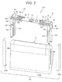
- FIG. 2 is an exploded perspective view illustrating a configuration of the rectangular secondary battery 100
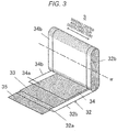
- FIG. 3 is a perspective view illustrating a developed wound group 3 provided in the rectangular secondary battery 100.
- the rectangular secondary battery 100 has a battery container 2 which is provided by a battery can 1 and a battery cover 6.
- the material of the battery can 1 and the battery cover 6 is aluminum or aluminum alloy.
- the battery can 1 is formed by a deep drawing to a metal material into a rectangular parallelepiped flat box shape having an opening on one surface.
- the battery can 1 has a rectangular bottom surface 1d, a pair of wide side surfaces 1b each of which is adjacent to each long side of the bottom surface 1d, and a pair of narrow side surfaces 1c each of which is adjacent to each short side of the bottom surface 1d.
- the battery cover 6 has a rectangular flat shape, and welded to the battery can 1 by laser beam welding to cover the opening of the battery can 1. Namely, the battery cover 6 seals the opening of the battery can 1. Further, the battery cover 6 has a positive electrode side terminal component part 60 which is electrically connected to a positive electrode 34 (see FIG. 3 ) in the wound group 3 and a negative electrode side terminal component part 70 which is electrically connected to a negative electrode 32 (see FIG. 3 ) in the wound group 3.
- the positive electrode side terminal component part 60 is provided with a positive electrode bolt 14, a positive electrode connection terminal 62, a positive electrode outer terminal 63, a positive electrode side outer insulator 24, and a gasket (not shown) and a positive electrode collector 180 which are arranged inside the battery can 1.
- the positive electrode bolt 14, the positive electrode outer terminal 63, the positive electrode connection terminal 62, the gasket and the positive electrode collector 180 are integrally assembled and mounted to the battery cover 6. In this state, the positive electrode collector 180, the positive electrode connection terminal 62 and the positive electrode outer terminal 63 are electrically connected with each other. Further, the positive electrode collector 180, the positive electrode connection terminal 62 and the positive electrode outer terminal 63 are insulated from the battery cover 6 by the positive electrode side outer insulator 24 and the gasket.
- the negative electrode side terminal component part 70 is provided with a negative electrode bolt 12, a negative electrode connection terminal 72, a negative electrode outer terminal 73, a negative electrode side outer insulator 22, and a gasket (not shown) and a negative electrode collector 190 which are arranged inside the battery can 1.
- the negative electrode side terminal component part 70 has a similar configuration to the positive electrode side terminal component part 60, and the negative electrode bolt 12, the negative electrode outer terminal 73, the negative electrode connection terminal 72 and the negative electrode collector 190 are integrally assembled and mounted to the battery cover 6. In this state, the negative electrode collector 190, the negative electrode connection terminal 72 and the negative electrode outer terminal 73 are electrically connected with each other. Further, the negative electrode collector 190, the negative electrode connection terminal 72 and the negative electrode outer terminal 73 are insulated from the battery cover 6 by the negative electrode side outer insulator 22 and the gasket.
- each of the positive electrode bolt 14 and the negative electrode bolt 12 protrudes outward of the battery cover 6 and has a screw construction. Accordingly, when the assembled cell is manufactured, the positive electrode bolt 14 or the negative electrode bolt 12 is inserted into a bus bar (not shown) which has a hole or a notch and assembled by means of a nut. With such a configuration, the positive electrode outer terminal 63 or the negative electrode outer terminal 73 is electrically connected with the bus bar.
- the battery cover 6 has a gas exhausting valve 10.
- the gas exhausting valve 10 is formed by thinning the battery cover 6 partially by press working. Further, the gas exhausting valve may be formed by a thin part of a thin film member to be weld to the opening of the battery cover 6 by laser welding.
- the gas exhausting valve 10 is torn and reduces the inner pressure of the battery container by exhausting gas in the battery container, when the inner pressure of the battery container is increased and reached to a predetermined pressure by gas generated by heat generation under an abnormal situation such as an overcharging of the rectangular secondary battery 100 and the like.
- an electrolyte injection hole (not shown) for injecting an electrolyte into the battery container is provided on the battery cover 6.
- the electrolyte injection hole is sealed by a sealing plug 11 after the electrolyte is injected into the battery container.
- a non-aqueous electrolyte may be used, in which a lithium salt such as a lithium hexafluorophosphate (LiPF 6 ) is dissolved into a carbon ester-based organic solvent such as an ethylene carbonate.
- the wound electrode group 3 (hereinafter also referred to as "wound group") which is held by a cover assembly 107 is housed in the battery can 1.
- the positive electrode collector 180 to be connected to the positive electrode 34 (see FIG. 3 ) of the wound group 3, the negative electrode collector 190 to be connected to the negative electrode 32 (see FIG. 3 ) of the wound group 3 and the wound group 3 are housed in the battery can 1 in a such manner that they are covered with an insulation case 108.
- the material of the insulation case 108 is a resin having an electrical insulation property such as a polypropylene, and the battery can 1 and the wound group 3 are electrically isolated from each other by the insulation case 108.
- the insulation case 108 is provided with an insulation case wide surface part 108a which covers a wide side surface of the wound group 3 and two insulation case end parts 108b which cover end parts of the wound group 3, however the insulation case 108 may have a structure in which the insulation case wide surface part 108a and the insulation case end part 108b are integrated with each other.
- the cover assembly 107 is provided by integrally assembling the positive electrode collector 180, the positive electrode connection terminal 62, the positive electrode outer terminal 63, the positive electrode bolt 14, the positive electrode side outer insulator 24, the negative electrode collector 190, the negative electrode connection terminal 72, the negative electrode outer terminal 73, the negative electrode bolt 12, the negative electrode side outer insulator 22, the gasket and the battery cover 6.
- the positive electrode outer terminal 63 is electrically connected to the positive electrode 34 (see FIG. 3 ) of the wound group 3 via the positive electrode collector 180, and the negative electrode outer terminal 73 is electrically connected to the negative electrode 32 (see FIG. 3 ) of the wound group 3 via the negative electrode collector 190.
- electricity is provided to an outer device from the wound group 3 via the positive electrode outer terminal 63 and the negative electrode outer terminal 73, or electricity is provided to the wound group 3 from an outer power generator via the positive electrode outer terminal 63 and the negative electrode outer terminal 73 and then the rectangular secondary battery 100 is charged.
- the positive electrode collector 180 is formed by aluminum or aluminum alloy.
- the positive electrode collector 180 has a flat-shaped base part 181 which is mounted along a lower surface of the battery cover 6, a pair of flat parts 182 which is bent downward at 90 degrees at both end parts of the base part 181 in its width direction, and flat-shaped connection flat parts 183 each of which is provided at each distal end of the pair of the flat parts 182.
- Each connection flat part 183 is connected to the wound group 3 by ultrasonic welding.
- Each connection flat part 183 is bent at an inclined angle against the flat part 182.
- connection flat parts 183 is inclined such that the connection flat parts 183 are receding in a short side direction of the battery cover 6 toward the outside from the center side of the battery cover 6 with respect to a long side direction of the battery cover 6. Both of the inclined directions of the connection flat parts 183 are opposite with each other, and both connection flat parts 183 are arranged at the same angle against the center surface and arranged in linear symmetry to the center surface.
- the pair of the connection flat parts 183 has a positive electrode foil exposing part 34b of the wound group 3 therebetween and is connected to the positive electrode foil exposing part 34b by ultrasonic welding in a state in which the positive electrode foil exposing part 34b of the wound group 3 is opened into a V-shape.
- the negative electrode collector 190 is formed by copper or copper alloy, however the negative electrode collector has a similar configuration to the positive electrode collector 180.
- the negative electrode collector 190 has a flat-shaped base part 191 which is mounted along a lower surface of the battery cover 6, a pair of flat parts 192 which is bent downward at 90 degrees at both end parts of the base part 191 in its width direction, and flat-shaped connection flat parts 193 each of which is provided at each distal ends of the pair of the flat parts 192.
- Each connection flat part 193 is connected to the wound group 3 by ultrasonic welding.
- Each connection flat part 193 is bent at an inclined angle against the flat part 192.
- connection flat parts 192 is inclined such that the connection flat parts 192 are receding in a short side direction of the battery cover 6 toward the outside from the center side of the battery cover 6 with respect to a long side direction of the battery cover 6. Both of the inclined directions of the connection flat parts 192 are opposite with each other, and both connection flat parts 192 are arranged at the same angle against the center surface and arranged in linear symmetry to the center surface.
- the pair of the connection flat parts 193 has a negative electrode foil exposing part 32b of the wound group 3 therebetween, and is connected to the negative electrode foil exposing part 32b by ultrasonic welding in a state in which the negative electrode foil exposing part 32b of the wound group 3 is opened into a V-shape.
- FIG. 3 shows a developed state of a winding end side of the wound group 3.
- the wound group 3 is a power generation element, which has a layered structure in which the elongate positive electrode 34 and the elongate negative electrode 32 are wound around a winding center axis W in a flat shape with separators 33, 35 interposed between them.
- the positive electrode 34 has a positive electrode mixture layer 34a provided by coating both surfaces of a positive electrode foil, which is served as a positive electrode collector, with a positive electrode active material mixture, and the positive electrode foil exposing part 34b in which the positive electrode active material mixture is not coated is provided at one end part on the positive electrode foil with respect to a width direction of the positive electrode foil.
- the negative electrode 32 has a negative electrode mixture layer 32a provided by coating both surfaces of a negative electrode foil, which is served as a negative electrode collector, with a negative electrode active material mixture, and the negative electrode foil exposing part 32b in which the negative electrode active material mixture is not coated is provided at another end part on the negative electrode foil with respect to a width direction of the negative electrode foil.
- the positive electrode foil exposing part 34b and the negative electrode foil exposing part 32b are areas exposing a metal surface of the electrode foils, and are wound such that the positive electrode foil exposing part 34b and the negative electrode foil exposing part 32b are respectively arranged at one end and another end in a direction of the winding center axis W (width direction in FIG. 3 ).
- a negative electrode mixture is provided by adding 10 pts.wt. polyvinylidene fluoride (hereinafter referred to as "PVDF”) as a binder into 100 pts.wt. amorphous carbon powder as a negative electrode active material, and then adding and mixing N-methyl pyrrolidone (hereinafter referred to as "NMP") as a dispersant solvent.
- PVDF polyvinylidene fluoride
- NMP N-methyl pyrrolidone
- the negative electrode mixture is coated on both surfaces of a copper foil (negative electrode foil) with a thickness of 10 ⁇ m except a welding part (negative electrode foil exposing part 32b). Thereafter the negative electrode 32 having a negative electrode active material coating part with a thickness of 70 ⁇ m excluding the thickness of the copper foil is obtained through a drying process, a pressing process and a cutting process.
- the amorphous carbon as the negative electrode active material is utilized as an example, however it is not limited to this.
- a natural graphite into or from which lithium ions are insertable or removable, carbon materials such as various artificial graphite materials, coke, or the like, a chemical compound of silicon or tin (for example SiO, TiSi2, etc.), or a composite material thereof may be utilized, and as a particle shape, scale-like, sphere-like, fiber-like, needle-like, mass-like shape or the like shape may be applicable and it is not limited to the specific shape.
- a positive electrode mixture is provided by adding 10 pts.wt. scale-like graphite as a conductive material and 10 pts.wt. PVDF as a binder into 100 pts. wt. lithium manganate (LiMn 2 O 4 ) as a positive electrode active material, and then adding and mixing NMP as a dispersant solvent.
- the positive electrode mixture is coated on both surfaces of an aluminum foil (positive electrode foil) with a thickness of 20 ⁇ m except a welding part (positive electrode foil exposing part 34b). Thereafter the positive electrode 34 having a positive electrode active material coating part with a thickness of 90 ⁇ m excluding the thickness of the aluminum foil is obtained through a drying process, a pressing process and a cutting process.
- the lithium manganate is utilized as an example of the positive electrode active material, however other lithium manganate having a spinel crystal structure, a lithium manganese compound oxide in which a part of the lithium manganate is substituted or doped with a metal element, a lithium cobaltate or a lithium titanate having a stratified crystal structure, or a lithium-metal complex oxide in which a part of the lithium cobaltate or the lithium titanate is substituted or doped with a metal element may be utilized.
- PVDF is utilized as an example of a binder for the mixture material layer coating part of the positive electrode 34 and the negative electrode 32, however polymers such as polytetrafluoroethylene (PTFE), polyethylene, polystyrene, polybutadiene, butyl rubber, nitrile rubber, styrene-butadiene rubber, polysulfide rubber, nitrocellulose, cyanoethyl cellulose, various latexes, acrylonitrile, vinyl fluoride, vinylidene fluoride, fluoride propylene, fluoride chloroprene, acrylic resin, or mixtures thereof may be utilized.
- PTFE polytetrafluoroethylene
- polyethylene polystyrene
- polybutadiene butyl rubber
- nitrile rubber styrene-butadiene rubber
- polysulfide rubber nitrocellulose
- cyanoethyl cellulose various latexes
- acrylonitrile vinyl fluoride
- both end parts in the width direction of the wound group 3 namely a direction of the winding center axis W which is perpendicular to a winding direction
- one end part is served as a layered part of the positive electrode 34
- another end part is served as a layered part of the negative electrode 32.
- the layered part of the positive electrode 34 provided at one end is formed by layering the positive electrode foil exposing part 34b where the positive electrode mixture layer 34a is not formed.
- the layered part of the negative electrode 32 provided at another end is formed by layering the negative electrode foil exposing part 32b where the negative electrode mixture layer 32a is not formed.
- Each of the layered part of the positive electrode foil exposing part 34b and the layered part of the negative electrode foil exposing part 32b is pressed in advance and, as mentioned above, connected to the positive electrode collector 180 or the negative electrode collector 190 of the cover assembly 107 by ultrasonic welding and then an electrode group assembly is provided.
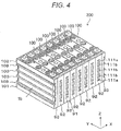
- FIG. 4 is a perspective view illustrating the module 200 of this embodiment.
- the orthogonal coordinate system in which a thickness direction, a width direction and a height direction of the rectangular secondary battery 100 during manufacture of the module 200, which respectively correspond to X-, Y- and Z-directions.
- the module 200 includes a plurality of rectangular secondary batteries 100 laminated in the thickness direction (X-direction) and a cell holder 91 which holds the rectangular secondary batteries 100 in a laminated state.
- the cell holder 91 may be, for example, made of resin material such as glass epoxy resin, polypropylene, polybutyrene telephthalate resin or the like, or metal material such as aluminum, copper, stainless steel or the like.
- the cell holder 91 is provided with a plurality of intermediate cell holders 92 and a pair of end cell holders 93.
- the intermediate cell holder 92 is interposed between the rectangular secondary batteries 100 adjacent to each other.
- the end cell holder 93 is arranged at both end parts in a laminated direction of the rectangular secondary batteries 100 held by the intermediate cell holder 92, and holds the rectangular secondary battery 100 between the end cell holder 93 and the intermediate cell holder 92.
- the end cell holder 93 has a shape substantially equal to one of two parts into which the intermediate cell holder 92 is divided with by a plane parallel to the wide side surface 1b of the rectangular secondary battery 100.
- a plurality of spacers 101, 102, 103 and openings 111a, 111b equipped by the intermediate cell holder 92 and the end cell holder 93 are described later.
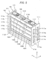
- FIG. 5 is a perspective view illustrating an assembled state of the pair of the intermediate cell holders 92 and the rectangular secondary battery 100.
- FIG. 6 is a perspective view illustrating an exploded state of the pair of the intermediate cell holders 92 and the rectangular secondary battery 100 shown in FIG. 5 .
- the intermediate cell holder 92 is, as shown in FIG. 5 and FIG. 6 , provided with a pair of side plates 111, 111 each of which faces each of a pair of narrow side surfaces 1c, 1c of the battery can 1 of the rectangular secondary battery 100, and a bottom plate 112 which faces a bottom surface 1d of the battery can 1.
- the intermediate cell holder 92 is formed plane-symmetrically with respect to a plane passing an intermediate point between two rectangular secondary batteries 100 and being parallel to the wide side surface 1b of the battery can 1.
- the side plate 111 and the bottom plate 112 of the intermediate cell holder 92 respectively face substantially half regions in the thickness direction of the battery can 1 of the narrow side surface 1c and the bottom surface 1d of two rectangular secondary batteries 100 arranged both sides of the intermediate cell holder 92.
- the pair of side plates 111, 111 is arranged at both end parts of the rectangular secondary battery 100 to face with each other in the width direction (Y-direction) of the wide side surface 1b of the battery can 1, that is in the width direction of the rectangular secondary battery 100, and extended in the laminated direction (X-direction) of the rectangular secondary batteries 100, that is in the thickness direction of the rectangular secondary battery 100.
- the bottom plate 112 is arranged at a lower part of the rectangular secondary battery 100 in a direction (Z-direction) perpendicular to the bottom surface 1d of the battery can 1, that is in the height direction of the rectangular secondary battery 100, and extended in the laminated direction of the rectangular secondary batteries 100 to connect lower parts of two side plates 111.
- two intermediate cell holders 92, 92 which are arranged at both sides of the rectangular secondary battery 100 is held in a state in which respective end parts of the side plates 111, 111 and end parts of the bottom plates 112, 112 are contacted or held with slight gap therebetween, and a space for holding the rectangular secondary battery 100 is provided between the intermediate cell holders 92.
- the pair of side plates 111, 111 is connected by the plurality of spacers 101, 102, 103. More specifically, the pair of side plates 111, 111 is connected by a lower part spacer 101 which connects lower parts of the side plates 111, 111, an upper part spacer 102 which connects upper parts of the side plates 111, 111 and an intermediate part spacer 103 which connects intermediate parts of the side plates 111, 111. A lower end of the lower part spacer 101 is connected to the bottom plate 112.
- the upper part spacer 102 is formed wider in the Z-direction than other spacers to correspond to the height from the battery cover 6 to a curved part of the wound group 3 at a side of the battery cover 6, which is housed in the battery can 1.
- a distance between the lower part spacer 101 and the intermediate part spacer 103 and a distance between the upper part spacer 102 and the intermediate part spacer 103 are shorter than a distance between the intermediate part spacers 103.
- Each spacer 101, 102, 103 is arranged between two battery cans 1 adjacent to each other. Namely, in the module 200, the rectangular secondary batteries 100 are laminated in the thickness direction by interposing the spacers 101, 102, 103 therebetween.
- the side plate 111 includes a first opening l11a and a second opening 111b.
- the first opening 111a is formed at a position between the lower part spacer 101 and the intermediate part spacer 103 and a position between the upper part spacer 102 and the intermediate part spacer 103 in the Z-direction.
- the second opening 111b is formed at a position between the intermediate part spacers 103 in the Z-direction.
- the first opening l11a and the second opening 111b have the same opening width in the X-direction.
- the opening height of the second opening 111b is larger than the opening height of the first opening l11a in accordance with intervals between respective spacers 101, 102, 103.
- the spacers 101, 102, 103 form a plurality of slots 114, 115 extending along the wide side surface 1b of the battery can 1 of the rectangular secondary battery 100 in the width direction (Y-direction) by being arranged at intervals in the Z-direction from each other.
- the first slot 114 which has relatively narrow width in the Z-direction is provided between the lower part spacer 101 and the intermediate part spacer 103 and between the upper part spacer 102 and the intermediate part spacer 103.
- the second slot 115 which has relatively wide width in the Z-direction is provided between the intermediate part spacers 103.
- the first slot 114 communicates with the first openings 111a of two side plates 111, and the second slot 115 communicates with the second openings 111b of two side plates 111.
- a coolant is passed through the slots 114, 115 and it makes possible to cool down the wide side surface 1b of the battery can 1 of the rectangular secondary battery 100.
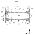
- FIG. 7 is a cross-sectional view of the intermediate cell holders 92, 92 taken by a XY- plane to include the intermediate part spacer 103 in the perspective view shown in FIG. 5 which illustrates the assembled state of the pair of intermediate cell holders 92, 92 and the rectangular secondary battery 100.
- the spacer 103 is divided into a plurality of parts in the height direction (Z-direction) of the wide side surface 1b of the battery can 1. Specifically, in examples shown in FIG. 5 and FIG. 6 , the spacer 103 is divided into four parts.
- the spacer 103 includes, as shown in FIG. 7 , a contact part 120 which contacts with a width direction end region R1 of the wide side surface 1b of the battery can 1 forming the battery container 2, a facing part 122 which faces a width direction intermediate region R2 of the wide side surface 1b, and an inclined surface 121 which is adjacent to both ends of the facing part 122 in the width direction (Y-direction) of the wide side surface 1b.
- the width direction end region R1 corresponds to a region starting from the end part toward the center of the wide side surface 1b of the battery can 1 in the width direction and having a predetermined width shorter than a length between the end part and the center of the wide side surface 1b of the battery can 1 in the width direction
- the width direction intermediate region R2 corresponds to a region between the width direction end regions R1.
- the contact part 120 is provided at both end parts of the spacer 103 in the width direction of the wide side surface 1b, and protruded toward the wide side surface 1b of the rectangular secondary battery 100 compared to the facing part 122.
- a thickness T1 of the contact part 120 in the thickness direction (X-direction) of the rectangular secondary battery 100 is thicker than a thickness T2 of the facing part 122 in the same direction.
- an interval D1 between the contact parts 120, 120 is narrower than an interval D2 between the facing parts 122, 122.
- the interval D2 between the facing parts 122, 122 is larger than the interval D1 between the contact parts 120, 120.
- surfaces of the contact part 120 and the facing part 122 which face the wide side surface 1b of the battery can 1 are respectively provided as a flat surface parallel to the width direction (Y-direction) and the height direction (Z-direction) of the rectangular secondary battery 100.
- the inclined surface 121 is inclined to asymptotically decrease a thickness of the spacer 103 with respect to the thickness direction of the rectangular secondary battery 100 in a direction toward the facing part 122 from the contact part 120, namely toward the width direction intermediate region R2 from the width direction end region R1 of the wide side surface 1b of the battery can 1. That is, in an example shown in FIG. 7 , the inclined surface 121 is inclined to decrease the thickness T1 of the contact part 120 of the spacer 103 in a direction toward the width direction intermediate region R2 from the width direction end region R1.
- the inclined surface 121 may be formed, for example in a linearly tapered shape or a curved shape with a predetermined curvature radius which connects the contact part 120 and the facing part 122, in the cross-sectional view shown in FIG. 7 .
- FIG. 8 is a front view which indicates a positional relationship between four of the intermediate part spacers 103 provided in the intermediate cell holder 92 and the end cell holder 93 which form the cell holder 91 and the wide side surface 1b of the battery can 1.
- the configuration of the cell holder 91 except the intermediate part spacer 103, which includes the lower part spacer 101 and the upper part spacer 102, is omitted to illustrate.
- the contact part 120 is provided at both ends of respective four spacers 103, and contacts with the width direction end region R1 of the wide side surface 1b of the battery can 1.
- the facing part 122 faces the width direction intermediate region R2 of the wide side surface 1b.
- the inclined surface 121 is arranged inside the contact part 120, and the facing part 122 is arranged inside the inclined surface 121.
- the inclined surface 121 is arranged at a whole region in the height direction (Z-direction) of the wide side surface 1b, namely at a position facing a height direction end region H1 and a height direction intermediate region H2, and arranged between the contact part 120 and the facing part 122 in the width direction (Y-direction) of the wide side surface 1b.
- the height direction end region H1 corresponds to a region starting from the upper end or the lower end toward the center of the wide side surface 1b of the battery can 1 in the height direction and having a predetermined width shorter than a length between the upper end part or the lower end part and the center of the wide side surface 1b of the battery can 1, and the height direction intermediate region H2 corresponds to a region between the height direction end regions H1, H1, which includes the center of the wide side surface 1b in the height direction.
- the contact parts 120 have the same length in the Y-direction between the four spacers 103, as well as the inclined surfaces 121 and the facing parts 122.
- the battery can 1 which forms the battery container 2 as described above is expanded by charging respective rectangular secondary batteries 100.
- the battery can 1 has a cross-sectional shape along the width direction, in which expansion of the center of the battery can 1 in the width direction is the largest and expansion is decreased asymptotically toward the end part in the width direction.
- the assembled cell 200 is manufactured by laminating the above-described expanded rectangular secondary batteries 100 in a state that the intermediate cell holder 92 is interposed therebetween, and arranging the end cell holders 93 at both end parts in the laminated direction and then applying a compression load in the laminated direction.
- the contact parts 120 of the intermediate part spacer 103 of the intermediate cell holder 92 and the end cell holder 93 contact with the width direction end region R1 of the wide side surface 1b of the battery can 1 and apply a load on the battery can 1 in the thickness direction.
- expansion of the battery can 1 in the width direction end region R1 of the wide side surface 1b of the battery can 1 is suppressed, and the width direction end region R1 of the wide side surface 1b is held stably and positioned precisely by the contact part 120 of the spacer 103.
- the height direction end region H1 of the wide side surface 1b of the battery can 1 is held stably and positioned precisely by the lower part spacers 101 and the upper part spacers 102 of the intermediate cell holder 92 and the end cell holder 93.
- a thickness of the expanded battery can 1 is larger than the interval D2 between the facing parts 122, 122 of the pair of spacers 103, 103 arranged at both sides of the battery can 1 in the thickness direction to face each other, the facing parts 122 contact with the wide side surface 1b, 1b of the battery can 1 and the wide side surface 1b of the battery can 1 is compressed in the thickness direction by the pair of facing parts 122, 122 facing each other.
- expansion of the wide side surface 1b of the battery can 1 forming the battery container 2 can be suppressed and to reduce a performance degradation of the battery becomes possible.
- the spacer 103 has, as shown in FIG. 7 , the inclined surface 121 which is adjacent to the facing part 122 in the width direction of the wide side surface 1b of the battery can 1, and the inclined surface 121 is inclined such that the thickness of the spacer 103 is decreased in a direction toward the width direction intermediate region R2 from the width direction end region R1.
- the inclined surface 121 is inclined along the wide side surface 1b of the battery can 1 expanded in a convex curvedmanner in which the thickness of the center part of the battery can 1 is the largest.
- the spacer 103 can prevent stress concentration from occurring on the wide side surface 1b of the battery can 1. With such a configuration, both of enhancing a reliability of the battery can 1 and reducing a performance degradation of the battery become possible.
- the inclined surface 121 is able to not only suppress expansion of the wide side surface 1b by contacting with the wide side surface 1b but also reduce stress applied on the wide side surface 1b compared to a configuration in which the inclined surface 121 is not formed.
- the inclined surface 121 is able to further reduce stress applied on the wide side surface 1b by contacting substantially whole area of the inclined surface 121 with the wide side surface 1b. Further, in a configuration in which the inclined angle of the inclined surface 121 is larger than the inclined angle of the wide side surface 1b, contact of the spacer 103 and the wide side surface 1b in a region between the contact part 120 and the facing part 122 is avoided, and stress concentration to be occurred between the inclined surface 121 and the wide side surface 1b of the battery can 1 is prevented.
- the interval D2 between the pair of facing parts 122, 122 is set to prevent expansion of the battery can 1 by contacting the facing part 122 with the wide side surface 1b of the battery can 1, when expansion of the battery can 1, which leads to a performance degradation of the rectangular secondary battery 100, is occurred. Accordingly, in a case in which expansion of the battery can 1, which leads to the performance degradation, is not occurred, the facing part 122 does not contact with the wide side surface 1b of the battery can 1.
- positioning accuracy of the rectangular secondary battery 100 can be improved by stably holding the width direction end region R1 of the wide side surface 1b of the battery can 1 which forms the battery container 2 of the rectangular secondary battery 100 by the contact parts 120, 120 of the spacers 103, 103. Further, stress concentration on the wide side surface 1b can be prevented by the inclined surface 121, and expansion of the battery container 2 can be suppressed by the facing part 122 which faces the width direction intermediate region R2 of the wide side surface 1b.
- FIG. 9 is a front view which indicates a positional relationship between a rectangular secondary battery 100 and intermediate part spacers 103, 103a of a rectangular secondary battery module as the assembled cell of this embodiment, which corresponds to FIG. 8 of Embodiment 1.
- the intermediate part spacer 103a which is provided in an intermediate cell holder 92 and an end cell holder 93 forming a cell holder 91 is different from the intermediate part spacer 103 of Embodiment 1 described above.
- Other configurations of the module of this embodiment are the same as those of the module 200 of the above-described Embodiment 1, and therefore the same reference numerals are assigned to the same configurations and the explanation of the configurations is omitted.
- two spacers 103, 103 which face a height direction intermediate region H2 of a wide side surface 1b of a battery can 1 has the same structure as the spacer 103 of Embodiment 1.
- two spacers 103a, 103a which face height direction end regions H1, H1 of the wide side surface 1b of the battery can 1 are different from the spacer 103 of Embodiment 1 in the point in which the inclined surface 121 is not formed.
- the inclined surface 121 which is provided in the spacers 103, 103 is arranged at a position facing the height direction intermediate region H2 of the wide side surface 1b of the battery can 1 and arranged between a contact part 120 and a facing part 122 in a width direction (Y-direction) of the wide side surface 1b.
- a length L0 of the contact part 120 of the spacer 103a in the width direction of the wide side surface 1b, which faces the height direction end region H1 of the wide side surface 1b is longer than a length L0 in the same direction of the contact part 120 of the spacer 103 arranged between those spacers 103a.
- the length L0 of the contact part 120 along the width direction of the wide side surface 1b becomes asymptotically longer in a direction toward the height direction end region H1 from the height direction intermediate region H2.
- a thickness of the battery can 1 is the largest at the center in both the height direction (Z-direction) and the width direction (Y-direction) of the wide side surface 1b of the battery can 1 and the thickness becomes smaller toward the end parts in each directions.
- the inclined surface 121 is not provided in the spacer 103a which faces the height direction end region H1 such as the module of this embodiment, stress concentration on the battery can 1 may not be occurred.
- the spacer 103 facing the height direction intermediate region of the wide side surface 1b of the battery can 1, which has the same configuration as that of Embodiment 1, is provided, a similar effect to that of the module 200 of Embodiment 1 is obtained.
- the length L0 of the contact part 120 along the width direction of the wide side surface 1b becomes asymptotically longer in a direction toward the height direction end region H1 from the height direction intermediate region H2, in the height direction end region H1 of the wide side surface 1b of the battery can 1, the width direction end region R1 of the wide side surface 1b can be held stably by the relatively longer contact part 120 of the spacer 103a.
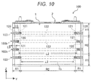
- FIG. 10 is a front view which indicates a positional relationship between a rectangular secondary battery 100 and intermediate part spacers 103, 103b of a rectangular secondary battery module as the assembled cell of this embodiment, which corresponds to FIG. 8 of Embodiment 1.
- a length L2 of a facing part 122 of the spacer 103b in a width direction (Y-direction) of a wide side surface 1b, which faces a height direction intermediate region H2 of the wide side surface 1b of a battery can 1 is longer than a length L2 in the same direction of the facing part 122 of the spacer 103 which faces a height direction end region H1.
- the length L2 of the facing part 122 along the width direction of the wide side surface 1b becomes asymptotically longer in a direction toward the height direction intermediate region H2 from the height direction end region H1.
- a length L0 in the same direction of the contact part 120 of the spacer 103 which faces the height direction end region H1 is longer than a length L0 in the same direction of the contact part 120 of the spacer 103b which faces the height direction intermediate region H2.
- the length L0 of the contact part 120 along the width direction of the wide side surface 1b of the battery can 1 becomes asymptotically longer in a direction toward the height direction end region H1 from the height direction intermediate region H2.
- Other configurations of the module of this embodiment are the same as those of the module 200 of the above-described Embodiment 1, and therefore the same reference numerals are assigned to the same configurations and the explanation of the configurations is omitted.
- a thickness of the battery can 1 is the largest at the center in both the height direction and the width direction of the wide side surface 1b of the battery can 1, and the thickness becomes smaller toward the end parts in each directions.
- the module of this embodiment a similar effect to that of the module 200 of the above-described Embodiment 1 is obtained, and with such a configuration in which the length L0 of the contact part 120 is set to become asymptotically longer in a direction toward the height direction end region H1 from the height direction intermediate region H2 of the wide side surface 1b, the width direction end region R1 can be held stably by the relatively longer contact part 120 in the height direction end region H1 of the battery can 1.
- the length L2 of the facing part 122 along the width direction of the wide side surface 1b of the battery can 1 becomes asymptotically longer in a direction toward the height direction intermediate region H2 from the height direction end region H1, in the height direction intermediate region H2, positions of the contact parts 120 are set to be close to both end parts of the spacer 103b. Accordingly, in the height direction intermediate region H2, stress concentration in the width direction end region R1 of the wide side surface 1b of the battery can 1 can be further relaxed.
- FIG. 11 is a front view which indicates a positional relationship between a rectangular secondary battery 100 and intermediate part spacers 103, 103c of a rectangular secondary battery module as the assembled cell of this embodiment, which corresponds to FIG. 8 of Embodiment 1.
- the spacer 103 which is arranged at a position facing a height direction end region H1 among the intermediate part spacers 103, 103c has, similar to the spacer 103 of Embodiment 1, a contact part 120, an inclined surface 121 and a facing part 122.
- the spacer 103c which is arranged at a position facing a height direction intermediate region H2 has the inclined surface 121 and the facing part 122, but the spacer 103c does not have the contact part 120.
- the inclined surface 121 is arranged between the contact part 120 and the facing part 122 in the width direction of the wide side surface 1b.
- the inclined surface 121 is arranged at both end parts in the width direction of the wide side surface 1b of the battery can 1.
- a thickness of the battery can 1 is the largest at the center in both the height direction and the width direction of the wide side surface 1b of the battery can 1, and the thickness becomes smaller toward the end parts in each directions.
- the spacer 103 which has similar configuration to that of Embodiment 1 is arranged at the position facing the height direction end region H1 of the wide side surface 1b of the battery can 1 and the spacer 103c which faces the height direction intermediate region H2 does not have the contact part 120, not only a similar effect to that of the module 200 of Embodiment 1 is obtained but also to further relax stress concentration in the height direction intermediate region H2 becomes possible.
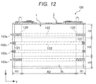
- FIG. 12 is a front view which indicates a positional relationship between a rectangular secondary battery 100 and intermediate part spacers 103a, 103c of a rectangular secondary battery module as the assembled cell of this embodiment, which corresponds to FIG. 8 of Embodiment 1.
- the spacer 103a which faces a height direction end region H1 of a wide side surface 1b of a battery can 1 has a similar configuration to the spacer 103a of the above-described Embodiment 2
- the spacer 103c which faces a height direction intermediate region H2 of the wide side surface 1b has a similar configuration to the spacer 103c of the above-described Embodiment 4.
- the spacer 103a which is arranged at a position facing the height direction end region H1 among the intermediate part spacers 103a, 103c has a contact part 120 and a facing part 122, but the spacer 103a does not have an inclined surface 121.
- the spacer 103c which is arranged at a position facing the height direction intermediate region H2 has the inclined surface 121 and the facing part 122, but the spacer 103 does not have the contact part 120.
- Other configurations of the module of this embodiment are the same as those of the module 200 of the above-described Embodiment 1, and therefore the same reference numerals are assigned to the same configurations and the explanation of the configurations is omitted.
- a thickness of the battery can 1 is the largest at the center in both a height direction and a width direction of the wide side surface 1b of the battery can 1, and the thickness becomes smaller toward the end parts in each directions.
- the spacer 130a which is arranged at the position facing the height direction end region H1 of the wide side surface 1b of the battery can 1 has a similar configuration to the spacer 130a of Embodiment 2 and the spacer 103c which is arranged at the position facing the height direction intermediate region H2 has a similar configuration to the spacer 103c of Embodiment 4, not only a similar effect to that of the module 200 of Embodiment 1 but also a similar effect to that of the module of Embodiment 2 and Embodiment 4 can be obtained.
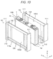
- FIG. 13 is a perspective view of an exploded rectangular secondary battery module as the assembled cell of this embodiment, which corresponds to FIG. 6 of Embodiment 1.
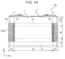
- FIG. 14 is a front view which indicates a positional relationship between a rectangular secondary battery 100 and an intermediate part spacer 103d of the module of this embodiment, which corresponds to FIG. 8 of Embodiment 1.
- the intermediate part spacer 103d of the module of this embodiment is provided as one piece in a height direction (Z-direction) of the rectangular secondary battery 100, and its lower end is connected to a lower part spacer 101 and its upper end is connected to an upper part spacer 102. Further, an intermediate cell holder 92 and an end cell holder 93 respectively have a notch part 112a on a bottom plate 112 for cooling the rectangular secondary battery 100 instead of the openings 111a, 111b and the slots 114, 115 of the side plate 111.
- the notch part 112a exposes a bottom surface 1d of the battery can 1 from the bottom plate 112 of the cell holders 92, 93 to make it possible to cool the rectangular secondary battery 100.
- Other configurations of the module of this embodiment are the same as those of the module 200 of the above-described Embodiment 1, and therefore the same reference numerals are assigned to the same configurations and the explanation of the configurations is omitted.
- the spacer 103d of this embodiment has a similar configuration to the spacer 103 shown in FIG. 7 and FIG. 8 of Embodiment 1 except that the spacer 103d is provided as one piece in the height direction of the rectangular secondary battery 100.
- the spacer 103d has a contact part 120 which contacts with a width direction end region R1 of a wide side surface 1b of the battery can 1, a facing part 122 which faces a width direction intermediate region R2 of the wide side surface 1b, and an inclined surface 121 which is adjacent to both ends of the facing part 122 in a width direction of the wide side surface 1b of the battery can 1.
- the inclined surface 121 is inclined such that a thickness of the spacer 103d is decreased in a direction toward the width direction intermediate region R2 from the width direction end region R1.
- the inclined surface 121 is inclined along the wide side surface 1b of the battery can 1 which is expanded in a convex curved manner in which the thickness of the center part of the battery can 1 is the largest. Accordingly, when the wide side surface 1b of the expanded battery can 1 is pressed by the contact part 120 or the facing part 122 of the spacer 103d, stress concentration on the wide side surface 1b of the battery can 1 can 1 can be prevented by the spacer 103. Thus, both of enhancing a reliability of the battery can 1 and reducing a battery performance degradation become possible.
- positioning accuracy of a rectangular secondary battery 100 can be enhanced by stably holding the width direction end region R1 of the wide side surface 1b of the battery can 1 which forms a battery container 2 of the rectangular secondary battery 100 by the contact parts 120, 120 of the spacers 103d, 103d. Further, stress concentration on the wide side surface 1b can be prevented by the inclined surface 121, and expansion of the battery container 2 can be suppressed by the facing part 122 which faces the width direction intermediate region R2 of the wide side surface 1b.
- the wide side surface 1b of the battery can 1 is pressed by the spacer 103d which is formed as one piece having a large area compared to the spacers 103 of Embodiment 1, which is divided into a plurality of pieces, expansion of the wide side surface 1b of the battery can 1 can be effectively suppressed and the battery performance degradation can be effectively reduced.
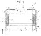
- FIG. 15 is a front view which indicates a positional relationship between a rectangular secondary battery 100 and an intermediate part spacer 103e of a module of this embodiment, which corresponds to FIG. 8 of Embodiment 1.
- the intermediate part spacer 103e of the module of this embodiment is, similar to the intermediate part spacer 103d of Embodiment 6, provided as one piece in a height direction (Z-direction) of the rectangular secondary battery 100.
- an inclined surface 121 of the intermediate part spacer 103e is, similar to the intermediate part spacers 103, 103a of Embodiment 2 shown in FIG. 9 , arranged at a position facing a height direction intermediate region H2 of a wide side surface 1b of a battery can 1, and arranged between a contact part 120 and a facing part 122 in a width direction (Y-direction) of the wide side surface 1b.
- the inclined surface 121 is not provided at a position facing a height direction end region H1 of the wide side surface 1b.
- a length L0 of the contact part 120 along the width direction of the wide side surface 1b becomes asymptotically longer in a direction toward the height direction end region H1 from the height direction intermediate region H2.
- Other configurations of the module of this embodiment are the same as those of the module 200 of the above-described Embodiment 1, and therefore the same reference numerals are assigned to the same configurations and the explanation of the configurations is omitted.
- the intermediate part spacer 103e is provided as one piece in the height direction of the rectangular secondary battery 100, a similar effect to that of the intermediate part spacer 103d of Embodiment 6 is obtained. Further, since the length L0 of the contact part 120 along the width direction of the wide side surface 1b becomes asymptotically longer in the direction toward the height direction end region H1 from the height direction intermediate region H2, similar to the spacer 103a of Embodiment 2, a width direction end region R1 can be held stably by the contact part 120 of the spacer 103a in the height direction end region H1 of the wide side surface 1b of the battery can 1.
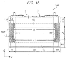
- FIG. 16 is a front view which indicates a positional relationship between a rectangular secondary battery 100 and an intermediate part spacer 103f of a module of this embodiment, which corresponds to FIG. 8 of Embodiment 1.
- the intermediate part spacer 103f of the module of this embodiment is, similar to the intermediate part spacer 103d of Embodiment 6, provided as one piece in a height direction (Z-direction) of the rectangular secondary battery 100.
- An inclined surface 121 of the intermediate part spacer 103f is, similar to the intermediate part spacers 103, 103b of Embodiment 3 shown in FIG. 10 , arranged at a position facing both of a height direction end region H1 and a height direction intermediate region H2 of a wide side surface 1b, and arranged between a contact part 120 and a facing part 122 in a width direction (Y-direction) of the wide side surface 1b.
- a length L2 of the facing part 122 facing the height direction intermediate region H2 of the wide side surface 1b of a battery can 1 with respect to the width direction of the wide side surface 1b is longer than a length L2 in the same direction of the facing part 122 facing the height direction end region H1.
- the length L2 of the facing part 122 along the width direction of the wide side surface 1b becomes asymptotically longer in a direction toward the height direction intermediate region H2 from the height direction end region H1.
- a length L0 of the contact part 120 in the same direction of the spacer 103f which faces the height direction end region H1 of the wide side surface 1b of the battery can 1 is longer than a length L0 in the same direction of the contact part 120 which faces the height direction intermediate region H2. Namely, the length L0 of the contact part 120 along the width direction of the wide side surface 1b of the battery can 1 becomes asymptotically longer toward the height direction end region H1 from the height direction intermediate region H2.
- Other configurations of the module of this embodiment are the same as those of the module 200 of the above-described Embodiment 1, and therefore the same reference numerals are assigned to the same configurations and the explanation of the configurations is omitted.
- the intermediate part spacer 103f is provided as one piece in the height direction of the rectangular secondary battery 100, a similar effect to that of the module of Embodiment 6 is obtained. Further, since the length L2 of the facing part 122 along the width direction of the wide side surface 1b becomes asymptotically longer in the direction toward the height direction intermediate region H2 from the height direction end region H1 and the length L0 of the contact part 120 along the same direction becomes asymptotically longer in the direction toward the height direction end region H1 from the height direction intermediate region H2, a similar effect to that of the module of Embodiment 3 can be obtained.
- FIG. 17 is a front view which indicates a positional relationship between a rectangular secondary battery 100 and an intermediate part spacer 103g of a module of this embodiment, which corresponds to FIG. 8 of Embodiment 1.
- the intermediate part spacer 103g of the module of this embodiment is, similar to the intermediate part spacer 103d of Embodiment 6, provided as one piece in a height direction (Z-direction) of the rectangular secondary battery 100.
- an inclined surface 121 is arranged at a position facing a height direction end region H1 of a wide side surface 1b, and arranged between a contact part 120 and a facing part 122 in a width direction (Y-direction) of the wide side surface 1b.
- the inclined surface 121 is arranged at a position facing a height direction intermediate region H2, and arranged at both end parts of the wide side surface 1b of a battery can 1 in the width direction.
- Other configurations of the module of this embodiment are the same as those of the module 200 of the above-described Embodiment 1, and therefore the same reference numerals are assigned to the same configurations and the explanation of the configurations is omitted.
- the intermediate part spacer 103g is provided as one piece in the height direction of the rectangular secondary battery 100, a similar effect to that of the module of Embodiment 6 is obtained. Further, since the inclined surface 121 is arranged at the position facing the height direction end region H1 of the wide side surface 1b and arranged between the contact part 120 and the facing part 122, and the inclined surface 121 is arranged at the position facing a height direction intermediate region H2 and arranged at both end parts in the width direction, a similar effect to that of the module of Embodiment 4 can be obtained.
- FIG. 18 is a front view which indicates a positional relationship between a rectangular secondary battery 100 and an intermediate part spacer 103h of a module of this embodiment, which corresponds to FIG. 8 of Embodiment 1.
- the intermediate part spacer 103h of the module of this embodiment is, similar to the intermediate part spacer 103d of Embodiment 6, provided as one piece in a height direction (Z-direction) of the rectangular secondary battery 100.
- the intermediate part spacer 103h has, similar to the intermediate part spacers 103a, 103c of Embodiment 5 shown in FIG. 12 , a contact part 120 and a facing part 122 at a position facing a height direction end region H1, and the intermediate part spacer 103h does not have an inclined surface 121 at the position facing the height direction end region H1. Further, the intermediate part spacer 103h has, similar to the intermediate part spacers 103a, 103c of Embodiment 5, the inclined surface 121 and the facing part 122 at a position facing a height direction intermediate region H2, and the intermediate part spacer 103h does not have the contact part 120 at the position facing the height direction intermediate region H2.
- the intermediate part spacer 103h is provided as one piece in the height direction of the rectangular secondary battery 100, a similar effect to that of the module of Embodiment 6 is obtained. Further, since the contact part 120 and the facing part 122 are provided at the position facing the height direction end region H1 and the inclined surface 121 and the facing part 122 are provided at the position facing the height direction intermediate region H2, a similar effect to that of the module of Embodiment 5 is obtained.
Landscapes
- Chemical & Material Sciences (AREA)
- Chemical Kinetics & Catalysis (AREA)
- Electrochemistry (AREA)
- General Chemical & Material Sciences (AREA)
- Engineering & Computer Science (AREA)
- Manufacturing & Machinery (AREA)
- Battery Mounting, Suspending (AREA)
- Secondary Cells (AREA)
Abstract
Description
- The present invention relates to an assembled cell in which a plurality of rectangular secondary batteries are laminated with a spacer interposed therebetween.
- In a rechargeable secondary battery field, an aqueous solution based battery such as a lead battery, a nickel cadmium battery or a nickel hydrogen battery has been mainly used. However, as an electric apparatus is downsized and reduced in weight, attention has been given to a lithium ion secondary battery with a high energy density, and research, development and commercialization of the lithium ion secondary battery is rapidly proceeded.
- Further, in a view of global warming or depletion of fuel resources, an electric vehicle (EV) or a hybrid electric vehicle (HEV) in which an electric motor assists a part of driving is developed by vehicle manufacturers, and a high-capacity and high-voltage secondary battery is required as a power source of the vehicle. As a power source which meets the requirement, a nonaqueous solution battery with high voltage is focused on. Especially, since a packed rectangular lithium ion secondary battery has an advantage of good volumetric efficiency, expectations for a development of the rectangular lithium ion secondary battery for the HEV or the EV have been increased.
- In large current application for the HEV or the EV, heat generation of the battery is unavoidable, and to cool the battery is necessary. Generally, in an assembled cell in which a plurality of batteries electrically connected in series or in parallel, gap is provided between each battery, and the battery is cooled by flowing coolant such as air into the gap. Further, in each battery forming the assembled cell, a battery container may be expanded when an electrode material housed in the battery container is expanded due to charging.
- As an assembled cell which is capable of reducing the expansion of the battery container, a secondary battery assembly in which secondary batteries are bound in a state in which a side surface having a maximum area (pressed surface) of outer surfaces of the secondary battery is partially compressed is disclosed (see Patent Literature 1 below).
- The secondary battery assembly described in Patent Literature 1 has a purpose, in a secondary battery which is used in a high rate in which the battery is repeatedly charged and discharged with a large current, to reduce a performance degradation of the secondary battery by holding the secondary batteries to keep uniform face pressure on the pressed surface, thus the secondary battery assembly has a contact member and a binding member as a solution means. The contact member has a plurality contact parts which is arranged discretely, each of which contacts with the pressed surface. The contact parts are formed to protrude from a connecting part toward the pressed surface, and the contact parts are arranged or formed to press less strongly a central region of the pressed surface between both one-side regions, the central region corresponding to a part close to the center of a wound electrode body in a winding axis direction. Specifically, to provide the contact member such that top of the contact member which contacts the pressed surface is curved to be concave at the center and pressing force to the pressed surface is different according to parts of the surface is described. On the other hand, to determine an arrangement of each member such that the contact member does not contact with an end part of,a cell case in order not to press the end part of the cell case is described.
- PTL 1:
WO 2011/158341 A - In the secondary battery assembly described in Patent Literature 1, expansion of the pressed surface is prevented by the contact member pressing the pressed surface of the cell. However, since the end part of the cell case is not fixed, a cell tends to move by vibration and the like of the vehicle on which the secondary battery assembly is mounted and there is a problem in positioning the cell. On the other hand, in a case in which the cell case is held by adding pressure on the end part of the cell case, stress concentration on the cell case might be occurred.
- An object of the present invention is, in consideration of the above-described problem, to provide an assembled cell which is able to improve positioning accuracy of a rectangular secondary battery by holding the rectangular secondary battery stably and to prevent stress concentration on a battery container and to suppress expansion of the battery container.
- To achieve the above-described object, an assembled cell of the present invention includes: a plurality of rectangular secondary batteries, each of which has a battery container formed in a flat box shape, and an electrode group in which a positive electrode and a negative electrode are wound, the electrode group being housed in the battery container; and a spacer which is interposed between the rectangular secondary batteries, the assembled cell being formed by the rectangular secondary batteries laminated in a thickness direction, wherein the spacer includes a contact part which contacts with a width direction end region of a wide side surface of the battery container, a facing part which faces a width direction intermediate region of the wide side surface, and an inclined surface which is adjacent to both ends of the facing part in a width direction of the wide side surface, and the inclined surface is inclined such that a thickness of the spacer is decreased in a direction toward the width direction intermediate region from the width direction end region.
- According to an assembled cell of the present invention, positioning accuracy can be enhanced by holding a width direction end region of a wide side surface of a battery container of a rectangular secondary battery between contact parts of spacers, and stress concentration to be occurred on the battery container can be prevented by an inclined surface of the spacer, and expansion of the battery container can be suppressed by a facing part which faces a width direction intermediate region of the wide side surface.
-
- [
FIG. 1] FIG. 1 is a perspective view illustrating an appearance of a rectangular secondary battery. - [
FIG. 2] FIG. 2 is an exploded perspective view of the rectangular secondary battery. - [
FIG. 3] FIG. 3 is a perspective view illustrating a developed wound group. - [
FIG. 4] FIG. 4 is a perspective view illustrating an appearance of a rectangular secondary battery module according to Embodiment 1. - [
FIG. 5] FIG. 5 is a perspective view illustrating the assembled rectangular secondary battery and a pair of cell holders of the module shown inFIG. 4 . - [
FIG. 6] FIG. 6 is an exploded perspective view of the module shown inFIG. 4 . - [
FIG. 7] FIG. 7 is a cross-sectional view illustrating a spacer of the module shown inFIG. 4 . - [
FIG. 8] FIG. 8 is a front view which indicates a positional relationship between the spacer and the rectangular secondary battery of the module shown inFIG. 4 . - [
FIG. 9] FIG. 9 is a front view which indicates a positional relationship between a rectangular secondary battery and a spacer of a module according toEmbodiment 2. - [
FIG. 10] FIG. 10 is a front view which indicates a positional relationship between a spacer and a rectangular secondary battery of a module according toEmbodiment 3. - [
FIG. 11] FIG. 11 is a front view which indicates a positional relationship between a spacer and a rectangular secondary battery of a module according toEmbodiment 4. - [
FIG. 12] FIG. 12 is a front view which indicates a positional relationship between a spacer, a rectangular secondary battery and a spacer of a module according to Embodiment 5. - [
FIG. 13] FIG. 13 is an exploded perspective view of a module according toEmbodiment 6. - [
FIG. 14] FIG. 14 is a front view which indicates a positional relationship between a spacer and a rectangular secondary battery of the module according toEmbodiment 6. - [
FIG. 15] FIG. 15 is a front view which indicates a positional relationship between a spacer and a rectangular secondary battery of a module according toEmbodiment 7. - [
FIG. 16] FIG. 16 is a front view which indicates a positional relationship between a spacer and a rectangular' secondary battery of a module according to Embodiment 8. - [
FIG. 17] FIG. 17 is a front view which indicates a positional relationship between a spacer and a rectangular secondary battery of a module according to Embodiment 9. - [
FIG. 18] FIG. 18 is a front view which indicates a positional relationship between a spacer and a rectangular secondary battery of a module according toEmbodiment 10. - Embodiments of a rectangular secondary battery module of an assembled cell of the present invention are described below with reference to drawings.
- First, a rectangular secondary battery provided in a rectangular secondary battery module according to this embodiment is described.
FIG. 1 is a perspective view illustrating an appearance of a rectangularsecondary battery 100 as one example of an electricity storage element, andFIG. 2 is an exploded perspective view illustrating a configuration of the rectangularsecondary battery 100.FIG. 3 is a perspective view illustrating a developedwound group 3 provided in the rectangularsecondary battery 100. - As shown in
FIG. 1 , the rectangularsecondary battery 100 has abattery container 2 which is provided by a battery can 1 and abattery cover 6. The material of the battery can 1 and thebattery cover 6 is aluminum or aluminum alloy. The battery can 1 is formed by a deep drawing to a metal material into a rectangular parallelepiped flat box shape having an opening on one surface. The battery can 1 has arectangular bottom surface 1d, a pair ofwide side surfaces 1b each of which is adjacent to each long side of thebottom surface 1d, and a pair ofnarrow side surfaces 1c each of which is adjacent to each short side of thebottom surface 1d. - The
battery cover 6 has a rectangular flat shape, and welded to the battery can 1 by laser beam welding to cover the opening of the battery can 1. Namely, the battery cover 6 seals the opening of the battery can 1. Further, thebattery cover 6 has a positive electrode sideterminal component part 60 which is electrically connected to a positive electrode 34 (seeFIG. 3 ) in thewound group 3 and a negative electrode sideterminal component part 70 which is electrically connected to a negative electrode 32 (seeFIG. 3 ) in thewound group 3. - The positive electrode side
terminal component part 60 is provided with apositive electrode bolt 14, a positiveelectrode connection terminal 62, a positive electrodeouter terminal 63, a positive electrode sideouter insulator 24, and a gasket (not shown) and apositive electrode collector 180 which are arranged inside the battery can 1. Thepositive electrode bolt 14, the positive electrodeouter terminal 63, the positiveelectrode connection terminal 62, the gasket and thepositive electrode collector 180 are integrally assembled and mounted to thebattery cover 6. In this state, thepositive electrode collector 180, the positiveelectrode connection terminal 62 and the positive electrodeouter terminal 63 are electrically connected with each other. Further, thepositive electrode collector 180, the positiveelectrode connection terminal 62 and the positive electrodeouter terminal 63 are insulated from thebattery cover 6 by the positive electrode sideouter insulator 24 and the gasket. - The negative electrode side
terminal component part 70 is provided with anegative electrode bolt 12, a negativeelectrode connection terminal 72, a negative electrodeouter terminal 73, a negative electrode sideouter insulator 22, and a gasket (not shown) and anegative electrode collector 190 which are arranged inside the battery can 1. The negative electrode sideterminal component part 70 has a similar configuration to the positive electrode sideterminal component part 60, and thenegative electrode bolt 12, the negative electrodeouter terminal 73, the negativeelectrode connection terminal 72 and thenegative electrode collector 190 are integrally assembled and mounted to thebattery cover 6. In this state, thenegative electrode collector 190, the negativeelectrode connection terminal 72 and the negative electrodeouter terminal 73 are electrically connected with each other. Further, thenegative electrode collector 190, the negativeelectrode connection terminal 72 and the negative electrodeouter terminal 73 are insulated from thebattery cover 6 by the negative electrode sideouter insulator 22 and the gasket. - Further, each of the
positive electrode bolt 14 and thenegative electrode bolt 12 protrudes outward of thebattery cover 6 and has a screw construction. Accordingly, when the assembled cell is manufactured, thepositive electrode bolt 14 or thenegative electrode bolt 12 is inserted into a bus bar (not shown) which has a hole or a notch and assembled by means of a nut. With such a configuration, the positive electrodeouter terminal 63 or the negative electrodeouter terminal 73 is electrically connected with the bus bar. - Further, the
battery cover 6 has agas exhausting valve 10. Thegas exhausting valve 10 is formed by thinning thebattery cover 6 partially by press working. Further, the gas exhausting valve may be formed by a thin part of a thin film member to be weld to the opening of thebattery cover 6 by laser welding. Thegas exhausting valve 10 is torn and reduces the inner pressure of the battery container by exhausting gas in the battery container, when the inner pressure of the battery container is increased and reached to a predetermined pressure by gas generated by heat generation under an abnormal situation such as an overcharging of the rectangularsecondary battery 100 and the like. - Further, an electrolyte injection hole (not shown) for injecting an electrolyte into the battery container is provided on the
battery cover 6. The electrolyte injection hole is sealed by a sealingplug 11 after the electrolyte is injected into the battery container. As the electrolyte, for example, a non-aqueous electrolyte may be used, in which a lithium salt such as a lithium hexafluorophosphate (LiPF6) is dissolved into a carbon ester-based organic solvent such as an ethylene carbonate. - Next, an inner structure of the battery can 1 is described. As shown in
FIG. 2 , the wound electrode group 3 (hereinafter also referred to as "wound group") which is held by acover assembly 107 is housed in the battery can 1. Thepositive electrode collector 180 to be connected to the positive electrode 34 (seeFIG. 3 ) of thewound group 3, thenegative electrode collector 190 to be connected to the negative electrode 32 (seeFIG. 3 ) of thewound group 3 and thewound group 3 are housed in the battery can 1 in a such manner that they are covered with aninsulation case 108. - The material of the
insulation case 108 is a resin having an electrical insulation property such as a polypropylene, and the battery can 1 and thewound group 3 are electrically isolated from each other by theinsulation case 108. Further, in this embodiment, theinsulation case 108 is provided with an insulation casewide surface part 108a which covers a wide side surface of thewound group 3 and two insulation case endparts 108b which cover end parts of thewound group 3, however theinsulation case 108 may have a structure in which the insulation casewide surface part 108a and the insulation case endpart 108b are integrated with each other. - The
cover assembly 107 is provided by integrally assembling thepositive electrode collector 180, the positiveelectrode connection terminal 62, the positive electrodeouter terminal 63, thepositive electrode bolt 14, the positive electrode sideouter insulator 24, thenegative electrode collector 190, the negativeelectrode connection terminal 72, the negative electrodeouter terminal 73, thenegative electrode bolt 12, the negative electrode sideouter insulator 22, the gasket and thebattery cover 6. - The positive electrode
outer terminal 63 is electrically connected to the positive electrode 34 (seeFIG. 3 ) of thewound group 3 via thepositive electrode collector 180, and the negative electrodeouter terminal 73 is electrically connected to the negative electrode 32 (seeFIG. 3 ) of thewound group 3 via thenegative electrode collector 190. With this configuration, electricity is provided to an outer device from thewound group 3 via the positive electrodeouter terminal 63 and the negative electrodeouter terminal 73, or electricity is provided to thewound group 3 from an outer power generator via the positive electrodeouter terminal 63 and the negative electrodeouter terminal 73 and then the rectangularsecondary battery 100 is charged. - The
positive electrode collector 180 is formed by aluminum or aluminum alloy. Thepositive electrode collector 180 has a flat-shapedbase part 181 which is mounted along a lower surface of thebattery cover 6, a pair offlat parts 182 which is bent downward at 90 degrees at both end parts of thebase part 181 in its width direction, and flat-shaped connectionflat parts 183 each of which is provided at each distal end of the pair of theflat parts 182. Each connectionflat part 183 is connected to thewound group 3 by ultrasonic welding. Each connectionflat part 183 is bent at an inclined angle against theflat part 182. The pair of connectionflat parts 183 is inclined such that the connectionflat parts 183 are receding in a short side direction of thebattery cover 6 toward the outside from the center side of thebattery cover 6 with respect to a long side direction of thebattery cover 6. Both of the inclined directions of the connectionflat parts 183 are opposite with each other, and both connectionflat parts 183 are arranged at the same angle against the center surface and arranged in linear symmetry to the center surface. The pair of the connectionflat parts 183 has a positive electrodefoil exposing part 34b of thewound group 3 therebetween and is connected to the positive electrodefoil exposing part 34b by ultrasonic welding in a state in which the positive electrodefoil exposing part 34b of thewound group 3 is opened into a V-shape. - The
negative electrode collector 190 is formed by copper or copper alloy, however the negative electrode collector has a similar configuration to thepositive electrode collector 180. Thenegative electrode collector 190 has a flat-shapedbase part 191 which is mounted along a lower surface of thebattery cover 6, a pair offlat parts 192 which is bent downward at 90 degrees at both end parts of thebase part 191 in its width direction, and flat-shaped connectionflat parts 193 each of which is provided at each distal ends of the pair of theflat parts 192. Each connectionflat part 193 is connected to thewound group 3 by ultrasonic welding. Each connectionflat part 193 is bent at an inclined angle against theflat part 192. The pair of connectionflat parts 192 is inclined such that the connectionflat parts 192 are receding in a short side direction of thebattery cover 6 toward the outside from the center side of thebattery cover 6 with respect to a long side direction of thebattery cover 6. Both of the inclined directions of the connectionflat parts 192 are opposite with each other, and both connectionflat parts 192 are arranged at the same angle against the center surface and arranged in linear symmetry to the center surface. The pair of the connectionflat parts 193 has a negative electrodefoil exposing part 32b of thewound group 3 therebetween, and is connected to the negative electrodefoil exposing part 32b by ultrasonic welding in a state in which the negative electrodefoil exposing part 32b of thewound group 3 is opened into a V-shape. - Next, the
wound group 3 is described.FIG. 3 shows a developed state of a winding end side of thewound group 3. Thewound group 3 is a power generation element, which has a layered structure in which the elongatepositive electrode 34 and the elongatenegative electrode 32 are wound around a winding center axis W in a flat shape withseparators - The
positive electrode 34 has a positiveelectrode mixture layer 34a provided by coating both surfaces of a positive electrode foil, which is served as a positive electrode collector, with a positive electrode active material mixture, and the positive electrodefoil exposing part 34b in which the positive electrode active material mixture is not coated is provided at one end part on the positive electrode foil with respect to a width direction of the positive electrode foil. Thenegative electrode 32 has a negativeelectrode mixture layer 32a provided by coating both surfaces of a negative electrode foil, which is served as a negative electrode collector, with a negative electrode active material mixture, and the negative electrodefoil exposing part 32b in which the negative electrode active material mixture is not coated is provided at another end part on the negative electrode foil with respect to a width direction of the negative electrode foil. The positive electrodefoil exposing part 34b and the negative electrodefoil exposing part 32b are areas exposing a metal surface of the electrode foils, and are wound such that the positive electrodefoil exposing part 34b and the negative electrodefoil exposing part 32b are respectively arranged at one end and another end in a direction of the winding center axis W (width direction inFIG. 3 ). - As to the
negative electrode 32, a negative electrode mixture is provided by adding 10 pts.wt. polyvinylidene fluoride (hereinafter referred to as "PVDF") as a binder into 100 pts.wt. amorphous carbon powder as a negative electrode active material, and then adding and mixing N-methyl pyrrolidone (hereinafter referred to as "NMP") as a dispersant solvent. The negative electrode mixture is coated on both surfaces of a copper foil (negative electrode foil) with a thickness of 10 µm except a welding part (negative electrodefoil exposing part 32b). Thereafter thenegative electrode 32 having a negative electrode active material coating part with a thickness of 70 µm excluding the thickness of the copper foil is obtained through a drying process, a pressing process and a cutting process. - Here, in this embodiment, the amorphous carbon as the negative electrode active material is utilized as an example, however it is not limited to this. As the negative electrode active material, a natural graphite into or from which lithium ions are insertable or removable, carbon materials such as various artificial graphite materials, coke, or the like, a chemical compound of silicon or tin (for example SiO, TiSi2, etc.), or a composite material thereof may be utilized, and as a particle shape, scale-like, sphere-like, fiber-like, needle-like, mass-like shape or the like shape may be applicable and it is not limited to the specific shape.
- As to the
positive electrode 34, a positive electrode mixture is provided by adding 10 pts.wt. scale-like graphite as a conductive material and 10 pts.wt. PVDF as a binder into 100 pts. wt. lithium manganate (LiMn2O4) as a positive electrode active material, and then adding and mixing NMP as a dispersant solvent. The positive electrode mixture is coated on both surfaces of an aluminum foil (positive electrode foil) with a thickness of 20 µm except a welding part (positive electrodefoil exposing part 34b). Thereafter thepositive electrode 34 having a positive electrode active material coating part with a thickness of 90 µm excluding the thickness of the aluminum foil is obtained through a drying process, a pressing process and a cutting process. - Further, in this embodiment, the lithium manganate is utilized as an example of the positive electrode active material, however other lithium manganate having a spinel crystal structure, a lithium manganese compound oxide in which a part of the lithium manganate is substituted or doped with a metal element, a lithium cobaltate or a lithium titanate having a stratified crystal structure, or a lithium-metal complex oxide in which a part of the lithium cobaltate or the lithium titanate is substituted or doped with a metal element may be utilized.
- Further, in this embodiment, PVDF is utilized as an example of a binder for the mixture material layer coating part of the
positive electrode 34 and thenegative electrode 32, however polymers such as polytetrafluoroethylene (PTFE), polyethylene, polystyrene, polybutadiene, butyl rubber, nitrile rubber, styrene-butadiene rubber, polysulfide rubber, nitrocellulose, cyanoethyl cellulose, various latexes, acrylonitrile, vinyl fluoride, vinylidene fluoride, fluoride propylene, fluoride chloroprene, acrylic resin, or mixtures thereof may be utilized. - As to both end parts in the width direction of the
wound group 3, namely a direction of the winding center axis W which is perpendicular to a winding direction, one end part is served as a layered part of thepositive electrode 34, and another end part is served as a layered part of thenegative electrode 32. The layered part of thepositive electrode 34 provided at one end is formed by layering the positive electrodefoil exposing part 34b where the positiveelectrode mixture layer 34a is not formed. The layered part of thenegative electrode 32 provided at another end is formed by layering the negative electrodefoil exposing part 32b where the negativeelectrode mixture layer 32a is not formed. Each of the layered part of the positive electrodefoil exposing part 34b and the layered part of the negative electrodefoil exposing part 32b is pressed in advance and, as mentioned above, connected to thepositive electrode collector 180 or thenegative electrode collector 190 of thecover assembly 107 by ultrasonic welding and then an electrode group assembly is provided. - Next, the rectangular
secondary battery module 200 as the assembled cell according to this embodiment is described.FIG. 4 is a perspective view illustrating themodule 200 of this embodiment. Hereinafter, it is described by the orthogonal coordinate system, in which a thickness direction, a width direction and a height direction of the rectangularsecondary battery 100 during manufacture of themodule 200, which respectively correspond to X-, Y- and Z-directions. - The
module 200 includes a plurality of rectangularsecondary batteries 100 laminated in the thickness direction (X-direction) and acell holder 91 which holds the rectangularsecondary batteries 100 in a laminated state. Thecell holder 91 may be, for example, made of resin material such as glass epoxy resin, polypropylene, polybutyrene telephthalate resin or the like, or metal material such as aluminum, copper, stainless steel or the like. - The
cell holder 91 is provided with a plurality ofintermediate cell holders 92 and a pair ofend cell holders 93. Theintermediate cell holder 92 is interposed between the rectangularsecondary batteries 100 adjacent to each other. Theend cell holder 93 is arranged at both end parts in a laminated direction of the rectangularsecondary batteries 100 held by theintermediate cell holder 92, and holds the rectangularsecondary battery 100 between theend cell holder 93 and theintermediate cell holder 92. Theend cell holder 93 has a shape substantially equal to one of two parts into which theintermediate cell holder 92 is divided with by a plane parallel to thewide side surface 1b of the rectangularsecondary battery 100. A plurality ofspacers openings intermediate cell holder 92 and theend cell holder 93 are described later. -
FIG. 5 is a perspective view illustrating an assembled state of the pair of theintermediate cell holders 92 and the rectangularsecondary battery 100.FIG. 6 is a perspective view illustrating an exploded state of the pair of theintermediate cell holders 92 and the rectangularsecondary battery 100 shown inFIG. 5 . Theintermediate cell holder 92 is, as shown inFIG. 5 andFIG. 6 , provided with a pair ofside plates secondary battery 100, and abottom plate 112 which faces abottom surface 1d of the battery can 1. As theintermediate cell holder 92 is arranged between two rectangularsecondary batteries 100, theintermediate cell holder 92 is formed plane-symmetrically with respect to a plane passing an intermediate point between two rectangularsecondary batteries 100 and being parallel to thewide side surface 1b of the battery can 1. Thus, theside plate 111 and thebottom plate 112 of theintermediate cell holder 92 respectively face substantially half regions in the thickness direction of the battery can 1 of thenarrow side surface 1c and thebottom surface 1d of two rectangularsecondary batteries 100 arranged both sides of theintermediate cell holder 92. - The pair of
side plates secondary battery 100 to face with each other in the width direction (Y-direction) of thewide side surface 1b of the battery can 1, that is in the width direction of the rectangularsecondary battery 100, and extended in the laminated direction (X-direction) of the rectangularsecondary batteries 100, that is in the thickness direction of the rectangularsecondary battery 100. Thebottom plate 112 is arranged at a lower part of the rectangularsecondary battery 100 in a direction (Z-direction) perpendicular to thebottom surface 1d of the battery can 1, that is in the height direction of the rectangularsecondary battery 100, and extended in the laminated direction of the rectangularsecondary batteries 100 to connect lower parts of twoside plates 111. Further, twointermediate cell holders secondary battery 100 is held in a state in which respective end parts of theside plates bottom plates secondary battery 100 is provided between theintermediate cell holders 92. - The pair of
side plates spacers side plates lower part spacer 101 which connects lower parts of theside plates upper part spacer 102 which connects upper parts of theside plates intermediate part spacer 103 which connects intermediate parts of theside plates lower part spacer 101 is connected to thebottom plate 112. Theupper part spacer 102 is formed wider in the Z-direction than other spacers to correspond to the height from thebattery cover 6 to a curved part of thewound group 3 at a side of thebattery cover 6, which is housed in the battery can 1. A distance between thelower part spacer 101 and theintermediate part spacer 103 and a distance between theupper part spacer 102 and theintermediate part spacer 103 are shorter than a distance between theintermediate part spacers 103. Eachspacer module 200, the rectangularsecondary batteries 100 are laminated in the thickness direction by interposing thespacers - The
side plate 111 includes a first opening l11a and asecond opening 111b. Thefirst opening 111a is formed at a position between thelower part spacer 101 and theintermediate part spacer 103 and a position between theupper part spacer 102 and theintermediate part spacer 103 in the Z-direction. Thesecond opening 111b is formed at a position between theintermediate part spacers 103 in the Z-direction. The first opening l11a and thesecond opening 111b have the same opening width in the X-direction. As to an opening height in the Z-direction of each opening, the opening height of thesecond opening 111b is larger than the opening height of the first opening l11a in accordance with intervals betweenrespective spacers - The
spacers slots wide side surface 1b of the battery can 1 of the rectangularsecondary battery 100 in the width direction (Y-direction) by being arranged at intervals in the Z-direction from each other. As corresponding to the intervals betweenrespective spacers first slot 114 which has relatively narrow width in the Z-direction is provided between thelower part spacer 101 and theintermediate part spacer 103 and between theupper part spacer 102 and theintermediate part spacer 103. Further, thesecond slot 115 which has relatively wide width in the Z-direction is provided between theintermediate part spacers 103. Thefirst slot 114 communicates with thefirst openings 111a of twoside plates 111, and thesecond slot 115 communicates with thesecond openings 111b of twoside plates 111. With such a configuration, a coolant is passed through theslots wide side surface 1b of the battery can 1 of the rectangularsecondary battery 100. - A detailed description of a configuration of the
intermediate part spacer 103 according to this embodiment is described below.FIG. 7 is a cross-sectional view of theintermediate cell holders intermediate part spacer 103 in the perspective view shown inFIG. 5 which illustrates the assembled state of the pair ofintermediate cell holders secondary battery 100. - The
spacer 103 is divided into a plurality of parts in the height direction (Z-direction) of thewide side surface 1b of the battery can 1. Specifically, in examples shown inFIG. 5 andFIG. 6 , thespacer 103 is divided into four parts. Thespacer 103 includes, as shown inFIG. 7 , acontact part 120 which contacts with a width direction end region R1 of thewide side surface 1b of the battery can 1 forming thebattery container 2, a facingpart 122 which faces a width direction intermediate region R2 of thewide side surface 1b, and aninclined surface 121 which is adjacent to both ends of the facingpart 122 in the width direction (Y-direction) of thewide side surface 1b. Here, the width direction end region R1 corresponds to a region starting from the end part toward the center of thewide side surface 1b of the battery can 1 in the width direction and having a predetermined width shorter than a length between the end part and the center of thewide side surface 1b of the battery can 1 in the width direction, and the width direction intermediate region R2 corresponds to a region between the width direction end regions R1. - The
contact part 120 is provided at both end parts of thespacer 103 in the width direction of thewide side surface 1b, and protruded toward thewide side surface 1b of the rectangularsecondary battery 100 compared to the facingpart 122. Namely, a thickness T1 of thecontact part 120 in the thickness direction (X-direction) of the rectangularsecondary battery 100 is thicker than a thickness T2 of the facingpart 122 in the same direction. With such a configuration, in the pair ofspacers contact parts parts parts contact parts contact part 120 and the facingpart 122 which face thewide side surface 1b of the battery can 1 are respectively provided as a flat surface parallel to the width direction (Y-direction) and the height direction (Z-direction) of the rectangularsecondary battery 100. - The
inclined surface 121 is inclined to asymptotically decrease a thickness of thespacer 103 with respect to the thickness direction of the rectangularsecondary battery 100 in a direction toward the facingpart 122 from thecontact part 120, namely toward the width direction intermediate region R2 from the width direction end region R1 of thewide side surface 1b of the battery can 1. That is, in an example shown inFIG. 7 , theinclined surface 121 is inclined to decrease the thickness T1 of thecontact part 120 of thespacer 103 in a direction toward the width direction intermediate region R2 from the width direction end region R1. Theinclined surface 121 may be formed, for example in a linearly tapered shape or a curved shape with a predetermined curvature radius which connects thecontact part 120 and the facingpart 122, in the cross-sectional view shown inFIG. 7 . -
FIG. 8 is a front view which indicates a positional relationship between four of theintermediate part spacers 103 provided in theintermediate cell holder 92 and theend cell holder 93 which form thecell holder 91 and thewide side surface 1b of the battery can 1. Here, the configuration of thecell holder 91 except theintermediate part spacer 103, which includes thelower part spacer 101 and theupper part spacer 102, is omitted to illustrate. - The
contact part 120 is provided at both ends of respective fourspacers 103, and contacts with the width direction end region R1 of thewide side surface 1b of the battery can 1. The facingpart 122 faces the width direction intermediate region R2 of thewide side surface 1b. In the width direction of thewide side surface 1b, theinclined surface 121 is arranged inside thecontact part 120, and the facingpart 122 is arranged inside theinclined surface 121. Theinclined surface 121 is arranged at a whole region in the height direction (Z-direction) of thewide side surface 1b, namely at a position facing a height direction end region H1 and a height direction intermediate region H2, and arranged between thecontact part 120 and the facingpart 122 in the width direction (Y-direction) of thewide side surface 1b. - Here, the height direction end region H1 corresponds to a region starting from the upper end or the lower end toward the center of the
wide side surface 1b of the battery can 1 in the height direction and having a predetermined width shorter than a length between the upper end part or the lower end part and the center of thewide side surface 1b of the battery can 1, and the height direction intermediate region H2 corresponds to a region between the height direction end regions H1, H1, which includes the center of thewide side surface 1b in the height direction. Thecontact parts 120 have the same length in the Y-direction between the fourspacers 103, as well as theinclined surfaces 121 and the facingparts 122. - Next, a function of the
spacer 103 according to this embodiment is described. When the assembledcell 200 is manufactured, the battery can 1 which forms thebattery container 2 as described above is expanded by charging respective rectangularsecondary batteries 100. When the battery can 1 is expanded, the battery can 1 has a cross-sectional shape along the width direction, in which expansion of the center of the battery can 1 in the width direction is the largest and expansion is decreased asymptotically toward the end part in the width direction. The assembledcell 200 is manufactured by laminating the above-described expanded rectangularsecondary batteries 100 in a state that theintermediate cell holder 92 is interposed therebetween, and arranging theend cell holders 93 at both end parts in the laminated direction and then applying a compression load in the laminated direction. - At this time, the
contact parts 120 of theintermediate part spacer 103 of theintermediate cell holder 92 and theend cell holder 93 contact with the width direction end region R1 of thewide side surface 1b of the battery can 1 and apply a load on the battery can 1 in the thickness direction. With such a configuration, expansion of the battery can 1 in the width direction end region R1 of thewide side surface 1b of the battery can 1 is suppressed, and the width direction end region R1 of thewide side surface 1b is held stably and positioned precisely by thecontact part 120 of thespacer 103. Further, the height direction end region H1 of thewide side surface 1b of the battery can 1 is held stably and positioned precisely by thelower part spacers 101 and theupper part spacers 102 of theintermediate cell holder 92 and theend cell holder 93. - Further, in a case in which a thickness of the expanded battery can 1 is larger than the interval D2 between the facing
parts spacers parts 122 contact with thewide side surface wide side surface 1b of the battery can 1 is compressed in the thickness direction by the pair of facingparts wide side surface 1b of the battery can 1 forming thebattery container 2 can be suppressed and to reduce a performance degradation of the battery becomes possible. - Further, the
spacer 103 according to this embodiment has, as shown inFIG. 7 , theinclined surface 121 which is adjacent to the facingpart 122 in the width direction of thewide side surface 1b of the battery can 1, and theinclined surface 121 is inclined such that the thickness of thespacer 103 is decreased in a direction toward the width direction intermediate region R2 from the width direction end region R1. Namely, theinclined surface 121 is inclined along thewide side surface 1b of the battery can 1 expanded in a convex curvedmanner in which the thickness of the center part of the battery can 1 is the largest. Accordingly, when thewide side surface 1b of the expanded battery can 1 is pressed by thecontact part 120 or the facingpart 122 of thespacer 103, thespacer 103 can prevent stress concentration from occurring on thewide side surface 1b of the battery can 1. With such a configuration, both of enhancing a reliability of the battery can 1 and reducing a performance degradation of the battery become possible. - For example, in a configuration in which an inclined angle of the
inclined surface 121 against the width direction (Y-direction) of thewide side surface 1b of the battery can 1 is smaller than an inclined angle of thewide side surface 1b of the expanded battery can 1, theinclined surface 121 is able to not only suppress expansion of thewide side surface 1b by contacting with thewide side surface 1b but also reduce stress applied on thewide side surface 1b compared to a configuration in which theinclined surface 121 is not formed. Further, in a configuration in which the inclined angle of theinclined surface 121 is substantially equal to the inclined angle of thewide side surface 1b of the expanded battery can 1, theinclined surface 121 is able to further reduce stress applied on thewide side surface 1b by contacting substantially whole area of theinclined surface 121 with thewide side surface 1b. Further, in a configuration in which the inclined angle of theinclined surface 121 is larger than the inclined angle of thewide side surface 1b, contact of thespacer 103 and thewide side surface 1b in a region between thecontact part 120 and the facingpart 122 is avoided, and stress concentration to be occurred between theinclined surface 121 and thewide side surface 1b of the battery can 1 is prevented. - Here, the interval D2 between the pair of facing
parts part 122 with thewide side surface 1b of the battery can 1, when expansion of the battery can 1, which leads to a performance degradation of the rectangularsecondary battery 100, is occurred. Accordingly, in a case in which expansion of the battery can 1, which leads to the performance degradation, is not occurred, the facingpart 122 does not contact with thewide side surface 1b of the battery can 1. - As described above, according to the rectangular
secondary battery module 200 as the assembled cell of this embodiment, positioning accuracy of the rectangularsecondary battery 100 can be improved by stably holding the width direction end region R1 of thewide side surface 1b of the battery can 1 which forms thebattery container 2 of the rectangularsecondary battery 100 by thecontact parts spacers wide side surface 1b can be prevented by theinclined surface 121, and expansion of thebattery container 2 can be suppressed by the facingpart 122 which faces the width direction intermediate region R2 of thewide side surface 1b. - Next, an assembled cell of the present invention according to
Embodiment 2 is described with reference toFIG. 1 to 7 andFIG. 9. FIG. 9 is a front view which indicates a positional relationship between a rectangularsecondary battery 100 andintermediate part spacers FIG. 8 of Embodiment 1. - In the module of this embodiment, the
intermediate part spacer 103a which is provided in anintermediate cell holder 92 and anend cell holder 93 forming acell holder 91 is different from theintermediate part spacer 103 of Embodiment 1 described above. Other configurations of the module of this embodiment are the same as those of themodule 200 of the above-described Embodiment 1, and therefore the same reference numerals are assigned to the same configurations and the explanation of the configurations is omitted. - In this embodiment, two
spacers wide side surface 1b of a battery can 1 has the same structure as thespacer 103 of Embodiment 1. On the other hand, twospacers wide side surface 1b of the battery can 1 are different from thespacer 103 of Embodiment 1 in the point in which theinclined surface 121 is not formed. - Namely, in this embodiment, the
inclined surface 121 which is provided in thespacers wide side surface 1b of the battery can 1 and arranged between acontact part 120 and a facingpart 122 in a width direction (Y-direction) of thewide side surface 1b. Further, a length L0 of thecontact part 120 of thespacer 103a in the width direction of thewide side surface 1b, which faces the height direction end region H1 of thewide side surface 1b, is longer than a length L0 in the same direction of thecontact part 120 of thespacer 103 arranged between thosespacers 103a. Namely, the length L0 of thecontact part 120 along the width direction of thewide side surface 1b becomes asymptotically longer in a direction toward the height direction end region H1 from the height direction intermediate region H2. - When the battery can 1 is expanded, a thickness of the battery can 1 is the largest at the center in both the height direction (Z-direction) and the width direction (Y-direction) of the
wide side surface 1b of the battery can 1 and the thickness becomes smaller toward the end parts in each directions. Thus, even though theinclined surface 121 is not provided in thespacer 103a which faces the height direction end region H1 such as the module of this embodiment, stress concentration on the battery can 1 may not be occurred. - Accordingly, according to the assembled cell of this embodiment, since the
spacer 103 facing the height direction intermediate region of thewide side surface 1b of the battery can 1, which has the same configuration as that of Embodiment 1, is provided, a similar effect to that of themodule 200 of Embodiment 1 is obtained. In addition, since the length L0 of thecontact part 120 along the width direction of thewide side surface 1b becomes asymptotically longer in a direction toward the height direction end region H1 from the height direction intermediate region H2, in the height direction end region H1 of thewide side surface 1b of the battery can 1, the width direction end region R1 of thewide side surface 1b can be held stably by the relatively longer contactpart 120 of the spacer 103a. - Next, an assembled cell of the present invention according to
Embodiment 3 is described with reference toFIGS. 1 to 7 andFIG. 10. FIG. 10 is a front view which indicates a positional relationship between a rectangularsecondary battery 100 andintermediate part spacers FIG. 8 of Embodiment 1. - In the module of this embodiment, a length L2 of a facing
part 122 of thespacer 103b in a width direction (Y-direction) of awide side surface 1b, which faces a height direction intermediate region H2 of thewide side surface 1b of a battery can 1, is longer than a length L2 in the same direction of the facingpart 122 of thespacer 103 which faces a height direction end region H1. Namely, the length L2 of the facingpart 122 along the width direction of thewide side surface 1b becomes asymptotically longer in a direction toward the height direction intermediate region H2 from the height direction end region H1. - Further, a length L0 in the same direction of the
contact part 120 of thespacer 103 which faces the height direction end region H1 is longer than a length L0 in the same direction of thecontact part 120 of thespacer 103b which faces the height direction intermediate region H2. Namely, the length L0 of thecontact part 120 along the width direction of thewide side surface 1b of the battery can 1 becomes asymptotically longer in a direction toward the height direction end region H1 from the height direction intermediate region H2. Other configurations of the module of this embodiment are the same as those of themodule 200 of the above-described Embodiment 1, and therefore the same reference numerals are assigned to the same configurations and the explanation of the configurations is omitted. - As described above, when the battery can 1 is expanded, a thickness of the battery can 1 is the largest at the center in both the height direction and the width direction of the
wide side surface 1b of the battery can 1, and the thickness becomes smaller toward the end parts in each directions. According to the module of this embodiment, a similar effect to that of themodule 200 of the above-described Embodiment 1 is obtained, and with such a configuration in which the length L0 of thecontact part 120 is set to become asymptotically longer in a direction toward the height direction end region H1 from the height direction intermediate region H2 of thewide side surface 1b, the width direction end region R1 can be held stably by the relatively longer contactpart 120 in the height direction end region H1 of the battery can 1. - Further, since the length L2 of the facing
part 122 along the width direction of thewide side surface 1b of the battery can 1 becomes asymptotically longer in a direction toward the height direction intermediate region H2 from the height direction end region H1, in the height direction intermediate region H2, positions of thecontact parts 120 are set to be close to both end parts of thespacer 103b. Accordingly, in the height direction intermediate region H2, stress concentration in the width direction end region R1 of thewide side surface 1b of the battery can 1 can be further relaxed. - Next, an assembled cell of the present invention according to
Embodiment 4 is described with reference toFIGS. 1 to 7 andFIG. 11. FIG. 11 is a front view which indicates a positional relationship between a rectangularsecondary battery 100 andintermediate part spacers FIG. 8 of Embodiment 1. - In the module of this embodiment, the
spacer 103 which is arranged at a position facing a height direction end region H1 among theintermediate part spacers spacer 103 of Embodiment 1, acontact part 120, aninclined surface 121 and a facingpart 122. On the other hand, thespacer 103c which is arranged at a position facing a height direction intermediate region H2 has theinclined surface 121 and the facingpart 122, but thespacer 103c does not have thecontact part 120. - Namely, in the
spacer 103 which faces the height direction end region H1 of thewide side surface 1b, theinclined surface 121 is arranged between thecontact part 120 and the facingpart 122 in the width direction of thewide side surface 1b. On the other hand, in thespacer 103c which faces the height direction intermediate region H2, theinclined surface 121 is arranged at both end parts in the width direction of thewide side surface 1b of the battery can 1. Other configurations of the module of this embodiment are the same as those of themodule 200 of the above-described Embodiment 1, and therefore the same reference numerals are assigned to the same configurations and the explanation of the configurations is omitted. - As described above, when the battery can 1 is expanded, a thickness of the battery can 1 is the largest at the center in both the height direction and the width direction of the
wide side surface 1b of the battery can 1, and the thickness becomes smaller toward the end parts in each directions. Thus, since thespacer 103 which has similar configuration to that of Embodiment 1 is arranged at the position facing the height direction end region H1 of thewide side surface 1b of the battery can 1 and thespacer 103c which faces the height direction intermediate region H2 does not have thecontact part 120, not only a similar effect to that of themodule 200 of Embodiment 1 is obtained but also to further relax stress concentration in the height direction intermediate region H2 becomes possible. - Next, an assembled cell of the present invention according to Embodiment 5 is described with reference to
FIGS. 1 to 7 andFIG. 12. FIG. 12 is a front view which indicates a positional relationship between a rectangularsecondary battery 100 andintermediate part spacers FIG. 8 of Embodiment 1. - In the module of this embodiment, the
spacer 103a which faces a height direction end region H1 of awide side surface 1b of a battery can 1 has a similar configuration to thespacer 103a of the above-describedEmbodiment 2, and thespacer 103c which faces a height direction intermediate region H2 of thewide side surface 1b has a similar configuration to thespacer 103c of the above-describedEmbodiment 4. - Namely, the
spacer 103a which is arranged at a position facing the height direction end region H1 among theintermediate part spacers contact part 120 and a facingpart 122, but thespacer 103a does not have aninclined surface 121. On the other hand, thespacer 103c which is arranged at a position facing the height direction intermediate region H2 has theinclined surface 121 and the facingpart 122, but thespacer 103 does not have thecontact part 120. Other configurations of the module of this embodiment are the same as those of themodule 200 of the above-described Embodiment 1, and therefore the same reference numerals are assigned to the same configurations and the explanation of the configurations is omitted. - As described above, when the battery can 1 is expanded, a thickness of the battery can 1 is the largest at the center in both a height direction and a width direction of the
wide side surface 1b of the battery can 1, and the thickness becomes smaller toward the end parts in each directions. According to the module of this embodiment, since the spacer 130a which is arranged at the position facing the height direction end region H1 of thewide side surface 1b of the battery can 1 has a similar configuration to the spacer 130a ofEmbodiment 2 and thespacer 103c which is arranged at the position facing the height direction intermediate region H2 has a similar configuration to thespacer 103c ofEmbodiment 4, not only a similar effect to that of themodule 200 of Embodiment 1 but also a similar effect to that of the module ofEmbodiment 2 andEmbodiment 4 can be obtained. - Next, an assembled cell of the present invention according to
Embodiment 6 is described with reference toFIGS. 1 to 4 ,FIG. 13 andFIG. 14 .FIG. 13 is a perspective view of an exploded rectangular secondary battery module as the assembled cell of this embodiment, which corresponds toFIG. 6 of Embodiment 1.FIG. 14 is a front view which indicates a positional relationship between a rectangularsecondary battery 100 and anintermediate part spacer 103d of the module of this embodiment, which corresponds toFIG. 8 of Embodiment 1. - The
intermediate part spacer 103d of the module of this embodiment is provided as one piece in a height direction (Z-direction) of the rectangularsecondary battery 100, and its lower end is connected to alower part spacer 101 and its upper end is connected to anupper part spacer 102. Further, anintermediate cell holder 92 and anend cell holder 93 respectively have anotch part 112a on abottom plate 112 for cooling the rectangularsecondary battery 100 instead of theopenings slots side plate 111. When the rectangularsecondary battery 100 is assembled to acell holder 91, thenotch part 112a exposes abottom surface 1d of the battery can 1 from thebottom plate 112 of thecell holders secondary battery 100. Other configurations of the module of this embodiment are the same as those of themodule 200 of the above-described Embodiment 1, and therefore the same reference numerals are assigned to the same configurations and the explanation of the configurations is omitted. - The
spacer 103d of this embodiment has a similar configuration to thespacer 103 shown inFIG. 7 andFIG. 8 of Embodiment 1 except that thespacer 103d is provided as one piece in the height direction of the rectangularsecondary battery 100. Namely, thespacer 103d has acontact part 120 which contacts with a width direction end region R1 of awide side surface 1b of the battery can 1, a facingpart 122 which faces a width direction intermediate region R2 of thewide side surface 1b, and aninclined surface 121 which is adjacent to both ends of the facingpart 122 in a width direction of thewide side surface 1b of the battery can 1. - Further, the
inclined surface 121 is inclined such that a thickness of thespacer 103d is decreased in a direction toward the width direction intermediate region R2 from the width direction end region R1. With such a configuration, theinclined surface 121 is inclined along thewide side surface 1b of the battery can 1 which is expanded in a convex curved manner in which the thickness of the center part of the battery can 1 is the largest. Accordingly, when thewide side surface 1b of the expanded battery can 1 is pressed by thecontact part 120 or the facingpart 122 of thespacer 103d, stress concentration on thewide side surface 1b of the battery can 1 can be prevented by thespacer 103. Thus, both of enhancing a reliability of the battery can 1 and reducing a battery performance degradation become possible. - Accordingly, according to the module of this embodiment, similar to the
module 200 of Embodiment 1, positioning accuracy of a rectangularsecondary battery 100 can be enhanced by stably holding the width direction end region R1 of thewide side surface 1b of the battery can 1 which forms abattery container 2 of the rectangularsecondary battery 100 by thecontact parts spacers wide side surface 1b can be prevented by theinclined surface 121, and expansion of thebattery container 2 can be suppressed by the facingpart 122 which faces the width direction intermediate region R2 of thewide side surface 1b. Further, since thewide side surface 1b of the battery can 1 is pressed by thespacer 103d which is formed as one piece having a large area compared to thespacers 103 of Embodiment 1, which is divided into a plurality of pieces, expansion of thewide side surface 1b of the battery can 1 can be effectively suppressed and the battery performance degradation can be effectively reduced. - Next, an assembled cell of the present invention according to
Embodiment 7 is described with reference toFIGS. 1 to 4 ,FIG. 13 andFIG. 15. FIG. 15 is a front view which indicates a positional relationship between a rectangularsecondary battery 100 and anintermediate part spacer 103e of a module of this embodiment, which corresponds toFIG. 8 of Embodiment 1. - The
intermediate part spacer 103e of the module of this embodiment is, similar to theintermediate part spacer 103d ofEmbodiment 6, provided as one piece in a height direction (Z-direction) of the rectangularsecondary battery 100. Further, aninclined surface 121 of theintermediate part spacer 103e is, similar to theintermediate part spacers Embodiment 2 shown inFIG. 9 , arranged at a position facing a height direction intermediate region H2 of awide side surface 1b of a battery can 1, and arranged between acontact part 120 and a facingpart 122 in a width direction (Y-direction) of thewide side surface 1b. On the other hand, theinclined surface 121 is not provided at a position facing a height direction end region H1 of thewide side surface 1b. - Further, similar to
Embodiment 2, a length L0 of thecontact part 120 along the width direction of thewide side surface 1b becomes asymptotically longer in a direction toward the height direction end region H1 from the height direction intermediate region H2. Other configurations of the module of this embodiment are the same as those of themodule 200 of the above-described Embodiment 1, and therefore the same reference numerals are assigned to the same configurations and the explanation of the configurations is omitted. - According to the module of this embodiment, since the
intermediate part spacer 103e is provided as one piece in the height direction of the rectangularsecondary battery 100, a similar effect to that of theintermediate part spacer 103d ofEmbodiment 6 is obtained. Further, since the length L0 of thecontact part 120 along the width direction of thewide side surface 1b becomes asymptotically longer in the direction toward the height direction end region H1 from the height direction intermediate region H2, similar to thespacer 103a ofEmbodiment 2, a width direction end region R1 can be held stably by thecontact part 120 of thespacer 103a in the height direction end region H1 of thewide side surface 1b of the battery can 1. - Next, an assembled cell of the present invention according to Embodiment 8 is described with reference to
FIGS. 1 to 4 ,FIG. 13 andFIG. 16. FIG. 16 is a front view which indicates a positional relationship between a rectangularsecondary battery 100 and anintermediate part spacer 103f of a module of this embodiment, which corresponds toFIG. 8 of Embodiment 1. - The
intermediate part spacer 103f of the module of this embodiment is, similar to theintermediate part spacer 103d ofEmbodiment 6, provided as one piece in a height direction (Z-direction) of the rectangularsecondary battery 100. Aninclined surface 121 of theintermediate part spacer 103f is, similar to theintermediate part spacers Embodiment 3 shown inFIG. 10 , arranged at a position facing both of a height direction end region H1 and a height direction intermediate region H2 of awide side surface 1b, and arranged between acontact part 120 and a facingpart 122 in a width direction (Y-direction) of thewide side surface 1b. - Further, similar to the
intermediate part spacers Embodiment 3 shown inFIG. 10 , in theinclined surface 121 of theintermediate part spacer 103f, a length L2 of the facingpart 122 facing the height direction intermediate region H2 of thewide side surface 1b of a battery can 1 with respect to the width direction of thewide side surface 1b is longer than a length L2 in the same direction of the facingpart 122 facing the height direction end region H1. Namely, the length L2 of the facingpart 122 along the width direction of thewide side surface 1b becomes asymptotically longer in a direction toward the height direction intermediate region H2 from the height direction end region H1. - Further, a length L0 of the
contact part 120 in the same direction of thespacer 103f which faces the height direction end region H1 of thewide side surface 1b of the battery can 1 is longer than a length L0 in the same direction of thecontact part 120 which faces the height direction intermediate region H2. Namely, the length L0 of thecontact part 120 along the width direction of thewide side surface 1b of the battery can 1 becomes asymptotically longer toward the height direction end region H1 from the height direction intermediate region H2. Other configurations of the module of this embodiment are the same as those of themodule 200 of the above-described Embodiment 1, and therefore the same reference numerals are assigned to the same configurations and the explanation of the configurations is omitted. - According to the module of this embodiment, since the
intermediate part spacer 103f is provided as one piece in the height direction of the rectangularsecondary battery 100, a similar effect to that of the module ofEmbodiment 6 is obtained. Further, since the length L2 of the facingpart 122 along the width direction of thewide side surface 1b becomes asymptotically longer in the direction toward the height direction intermediate region H2 from the height direction end region H1 and the length L0 of thecontact part 120 along the same direction becomes asymptotically longer in the direction toward the height direction end region H1 from the height direction intermediate region H2, a similar effect to that of the module ofEmbodiment 3 can be obtained. - Next, an assembled cell of the present invention according to Embodiment 9 is described with reference to
FIGS. 1 to 4 ,FIG. 13 andFIG. 17. FIG. 17 is a front view which indicates a positional relationship between a rectangularsecondary battery 100 and anintermediate part spacer 103g of a module of this embodiment, which corresponds toFIG. 8 of Embodiment 1. - The
intermediate part spacer 103g of the module of this embodiment is, similar to theintermediate part spacer 103d ofEmbodiment 6, provided as one piece in a height direction (Z-direction) of the rectangularsecondary battery 100. - In the
intermediate part spacer 103g, similar to theintermediate part spacers Embodiment 4 shown inFIG. 11 , aninclined surface 121 is arranged at a position facing a height direction end region H1 of awide side surface 1b, and arranged between acontact part 120 and a facingpart 122 in a width direction (Y-direction) of thewide side surface 1b. On the other hand, theinclined surface 121 is arranged at a position facing a height direction intermediate region H2, and arranged at both end parts of thewide side surface 1b of a battery can 1 in the width direction. Other configurations of the module of this embodiment are the same as those of themodule 200 of the above-described Embodiment 1, and therefore the same reference numerals are assigned to the same configurations and the explanation of the configurations is omitted. - According to the module of this embodiment, since the
intermediate part spacer 103g is provided as one piece in the height direction of the rectangularsecondary battery 100, a similar effect to that of the module ofEmbodiment 6 is obtained. Further, since theinclined surface 121 is arranged at the position facing the height direction end region H1 of thewide side surface 1b and arranged between thecontact part 120 and the facingpart 122, and theinclined surface 121 is arranged at the position facing a height direction intermediate region H2 and arranged at both end parts in the width direction, a similar effect to that of the module ofEmbodiment 4 can be obtained. - Next, an assembled cell of the present invention according to
Embodiment 10 is described with reference toFIGS. 1 to FIG. 4 ,FIG. 13 andFIG. 18. FIG. 18 is a front view which indicates a positional relationship between a rectangularsecondary battery 100 and anintermediate part spacer 103h of a module of this embodiment, which corresponds toFIG. 8 of Embodiment 1. - The
intermediate part spacer 103h of the module of this embodiment is, similar to theintermediate part spacer 103d ofEmbodiment 6, provided as one piece in a height direction (Z-direction) of the rectangularsecondary battery 100. - The
intermediate part spacer 103h has, similar to theintermediate part spacers FIG. 12 , acontact part 120 and a facingpart 122 at a position facing a height direction end region H1, and theintermediate part spacer 103h does not have aninclined surface 121 at the position facing the height direction end region H1. Further, theintermediate part spacer 103h has, similar to theintermediate part spacers inclined surface 121 and the facingpart 122 at a position facing a height direction intermediate region H2, and theintermediate part spacer 103h does not have thecontact part 120 at the position facing the height direction intermediate region H2. - According to the module of this embodiment, since the
intermediate part spacer 103h is provided as one piece in the height direction of the rectangularsecondary battery 100, a similar effect to that of the module ofEmbodiment 6 is obtained. Further, since thecontact part 120 and the facingpart 122 are provided at the position facing the height direction end region H1 and theinclined surface 121 and the facingpart 122 are provided at the position facing the height direction intermediate region H2, a similar effect to that of the module of Embodiment 5 is obtained. - As described above, Embodiments according to the present invention are described in detail with reference to the drawings, however the specific configuration is not limited to these embodiments, and various design changes within the scope of the present invention may be also included in the present invention.
-
- 1
- battery can (battery container)
- 1b
- wide side surface
- 2
- battery container
- 3
- wound group (electrode group)
- 6
- battery cover (battery container)
- 32
- negative electrode
- 34
- positive electrode
- 100
- rectangular secondary battery
- 103
- spacer
- 120
- contact part
- 121
- inclined surface
- 122
- facing part
- 200
- module (assembled cell)
- L0
- length of the contact part
- L2
- length of the facing part
- R1
- width direction end region
- R2
- width direction intermediate region
- H1
- height direction end region
- H2
- height direction intermediate region
- X
- thickness direction
- Y
- width direction
- Z
- height direction
Claims (7)
- An assembled cell, comprising:a plurality of rectangular secondary batteries, each of which has a battery container formed in a flat box shape, and an electrode group in which a positive electrode and a negative electrode are wound, the electrode group being housed in the battery container; and a spacer which is interposed between the rectangular secondary batteries, the assembled cell being formed by the rectangular secondary batteries laminated in a thickness direction,wherein the spacer includes a contact part which contacts with a width direction end region of a wide side surface of the battery container, a facing part which faces a width direction intermediate region of the wide side surface, and an inclined surface which is adjacent to both ends of the facing part in a width direction of the wide side surface, andthe inclined surface is inclined such that a thickness of the spacer is decreased in a direction toward the width direction intermediate region from the width direction end region.
- The assembled cell according to claim 1, wherein the inclined surface is arranged at a position facing at least one of a height direction end region and a height direction intermediate region of the wide side surface and arranged between the contact part and the facing part in the width direction of the wide side surface.
- The assembled cell according to claim 2, wherein a length of the contact part along the width direction of the wide side surface is configured to become asymptotically longer in a direction toward the height direction end region from the height direction intermediate region.
- The assembled cell according to claim 1, wherein a length of the facing part along the width direction of the wide side surface is configured to become asymptotically longer in a direction toward the height direction intermediate region from the height direction end region.
- The assembled cell according to claim 4, wherein
the spacer includes the contact part, the inclined surface and the facing part at a position facing the height direction end region, and
the spacer includes the inclined surface and the facing part at a position facing the height direction intermediate region. - The assembled cell according to claim 4, wherein
the spacer includes the contact part and the facing part at a position facing the height direction end region, and
the spacer includes the inclined surface and the facing part at a position facing the height direction intermediate region. - The assembled cell according to any one of claims 1 through 6, wherein the spacer is divided into a plurality of pieces with respect to a height direction of the wide side surface.
Applications Claiming Priority (2)
| Application Number | Priority Date | Filing Date | Title |
|---|---|---|---|
| JP2013196990A JP6166994B2 (en) | 2013-09-24 | 2013-09-24 | Assembled battery |
| PCT/JP2014/070663 WO2015045632A1 (en) | 2013-09-24 | 2014-08-06 | Assembled cell |
Publications (3)
| Publication Number | Publication Date |
|---|---|
| EP3051606A1 true EP3051606A1 (en) | 2016-08-03 |
| EP3051606A4 EP3051606A4 (en) | 2017-03-29 |
| EP3051606B1 EP3051606B1 (en) | 2019-05-01 |
Family
ID=52742788
Family Applications (1)
| Application Number | Title | Priority Date | Filing Date |
|---|---|---|---|
| EP14849377.8A Active EP3051606B1 (en) | 2013-09-24 | 2014-08-06 | Assembled cell |
Country Status (5)
| Country | Link |
|---|---|
| US (1) | US10651442B2 (en) |
| EP (1) | EP3051606B1 (en) |
| JP (1) | JP6166994B2 (en) |
| CN (1) | CN105518904B (en) |
| WO (1) | WO2015045632A1 (en) |
Cited By (12)
| Publication number | Priority date | Publication date | Assignee | Title |
|---|---|---|---|---|
| WO2019071184A1 (en) * | 2017-10-06 | 2019-04-11 | Johnson Controls Technology Company | Lithium ion battery |
| US11063299B2 (en) | 2016-11-16 | 2021-07-13 | Enovix Corporation | Three-dimensional batteries with compressible cathodes |
| US11081718B2 (en) | 2016-05-13 | 2021-08-03 | Enovix Corporation | Dimensional constraints for three-dimensional batteries |
| US11128020B2 (en) | 2017-11-15 | 2021-09-21 | Enovix Corporation | Electrode assembly, secondary battery, and method of manufacture |
| US11205803B2 (en) | 2017-11-15 | 2021-12-21 | Enovix Corporation | Constrained electrode assembly |
| US11211639B2 (en) | 2018-08-06 | 2021-12-28 | Enovix Corporation | Electrode assembly manufacture and device |
| US11239488B2 (en) | 2015-05-14 | 2022-02-01 | Enovix Corporation | Longitudinal constraints for energy storage devices |
| EP3968447A1 (en) * | 2020-09-15 | 2022-03-16 | Lithium Power Inc. | Battery pack with a plurality of battery cells |
| US11355816B2 (en) | 2013-03-15 | 2022-06-07 | Enovix Operations Inc. | Separators for three-dimensional batteries |
| US11411253B2 (en) | 2020-12-09 | 2022-08-09 | Enovix Operations Inc. | Apparatus, systems and methods for the production of electrodes, electrode stacks and batteries |
| US11495784B2 (en) | 2020-09-18 | 2022-11-08 | Enovix Operations Inc. | Apparatus, systems and methods for the production of electrodes for use in batteries |
| US11600848B2 (en) | 2012-08-16 | 2023-03-07 | Enovix Corporation | Electrode structures for three-dimensional batteries |
Families Citing this family (22)
| Publication number | Priority date | Publication date | Assignee | Title |
|---|---|---|---|---|
| JP6166994B2 (en) * | 2013-09-24 | 2017-07-19 | 日立オートモティブシステムズ株式会社 | Assembled battery |
| JP2016152203A (en) * | 2015-02-19 | 2016-08-22 | 日立オートモティブシステムズ株式会社 | Battery pack |
| US10164296B2 (en) * | 2015-03-12 | 2018-12-25 | Johnson Controls Technology Company | Battery module separator plates |
| JP6547407B2 (en) * | 2015-05-18 | 2019-07-24 | 株式会社豊田自動織機 | Power storage device module |
| CN106340685B (en) * | 2015-07-13 | 2018-09-14 | 宁德时代新能源科技股份有限公司 | Secondary battery clamp |
| JP6876964B2 (en) * | 2015-09-30 | 2021-05-26 | パナソニックIpマネジメント株式会社 | Battery module |
| US10873111B2 (en) * | 2016-08-09 | 2020-12-22 | Wisk Aero Llc | Battery with compression and prevention of thermal runaway propagation features |
| JP6878975B2 (en) * | 2017-03-17 | 2021-06-02 | 三洋電機株式会社 | Batteries |
| JP6926946B2 (en) * | 2017-10-26 | 2021-08-25 | トヨタ自動車株式会社 | Batteries |
| US10756398B2 (en) | 2018-06-22 | 2020-08-25 | Wisk Aero Llc | Capacitance reducing battery submodule with thermal runaway propagation prevention and containment features |
| US10593920B2 (en) | 2018-08-13 | 2020-03-17 | Wisk Aero Llc | Capacitance reduction in battery systems |
| EP3951818A4 (en) | 2019-03-28 | 2022-06-01 | GS Yuasa International Ltd. | Electricity storage device |
| DE102019211253A1 (en) * | 2019-07-29 | 2021-02-04 | Elringklinger Ag | Galvanic cells and battery modules |
| CN111029488B (en) | 2019-08-14 | 2021-07-30 | 宁德时代新能源科技股份有限公司 | Secondary battery |
| CN111029489B (en) | 2019-08-14 | 2021-08-17 | 宁德时代新能源科技股份有限公司 | Secondary battery |
| CN110676518B (en) * | 2019-09-19 | 2020-06-26 | 宜宾锂宝新材料有限公司 | A kind of method for preventing lithium ion deposition in negative electrode of lithium ion battery |
| CN111564585B (en) * | 2020-04-27 | 2022-10-14 | 先进储能材料国家工程研究中心有限责任公司 | Square battery module |
| CN111490208B (en) * | 2020-04-27 | 2023-01-17 | 先进储能材料国家工程研究中心有限责任公司 | Energy storage battery box |
| KR20220017741A (en) * | 2020-08-05 | 2022-02-14 | 주식회사 엘지에너지솔루션 | A battery module having a structure capable of absorbing battery cell swelling, and a battery pack and vehicle comprising the same |
| KR102647832B1 (en) | 2021-01-11 | 2024-03-13 | 주식회사 엘지에너지솔루션 | Battery module and battery pack including the same |
| JP7651346B2 (en) * | 2021-03-29 | 2025-03-26 | イビデン株式会社 | Heat transfer suppression sheet for battery pack and battery pack |
| JP7503529B2 (en) * | 2021-08-27 | 2024-06-20 | プライムアースEvエナジー株式会社 | Battery Module and Spacer |
Family Cites Families (19)
| Publication number | Priority date | Publication date | Assignee | Title |
|---|---|---|---|---|
| JP4701652B2 (en) * | 2004-08-02 | 2011-06-15 | トヨタ自動車株式会社 | Assembled battery |
| JP4457931B2 (en) * | 2005-03-17 | 2010-04-28 | トヨタ自動車株式会社 | Battery module |
| KR100612239B1 (en) | 2005-04-26 | 2006-08-11 | 삼성에스디아이 주식회사 | Secondary battery partition wall forming the secondary battery module and the secondary battery module |
| JP5078052B2 (en) * | 2005-10-18 | 2012-11-21 | トヨタ自動車株式会社 | Battery module structure |
| JP2008282648A (en) * | 2007-05-10 | 2008-11-20 | Toyota Motor Corp | Assembled battery |
| JP5121395B2 (en) * | 2007-10-31 | 2013-01-16 | 三洋電機株式会社 | Battery pack and battery pack separator |
| JP5169471B2 (en) * | 2008-05-16 | 2013-03-27 | トヨタ自動車株式会社 | Power storage device and vehicle |
| CN101814623A (en) * | 2009-02-20 | 2010-08-25 | 日立麦克赛尔株式会社 | Battery pack and battery pack manufacturing method |
| JP5672000B2 (en) * | 2009-12-25 | 2015-02-18 | 株式会社Gsユアサ | Single cell and battery pack using the single cell |
| WO2011158341A1 (en) * | 2010-06-16 | 2011-12-22 | トヨタ自動車株式会社 | Secondary battery assembly |
| JP5645675B2 (en) * | 2011-01-07 | 2014-12-24 | 三菱電機株式会社 | Distributed simulation system |
| US9356268B2 (en) * | 2011-01-10 | 2016-05-31 | Samsung Sdi Co., Ltd. | Battery module |
| JP5598442B2 (en) | 2011-08-03 | 2014-10-01 | トヨタ自動車株式会社 | Battery module |
| JP2013073917A (en) | 2011-09-29 | 2013-04-22 | Lithium Energy Japan:Kk | Battery pack |
| WO2013080338A1 (en) * | 2011-11-30 | 2013-06-06 | 日立ビークルエナジー株式会社 | Cell block and cell module having same |
| JP5889333B2 (en) * | 2011-12-06 | 2016-03-22 | 日立オートモティブシステムズ株式会社 | Assembled battery |
| JP5821652B2 (en) | 2012-01-20 | 2015-11-24 | 株式会社Gsユアサ | Storage element module |
| JP6073583B2 (en) * | 2012-06-28 | 2017-02-01 | 三洋電機株式会社 | Power supply device, vehicle including this power supply device, and power storage device |
| JP6166994B2 (en) * | 2013-09-24 | 2017-07-19 | 日立オートモティブシステムズ株式会社 | Assembled battery |
-
2013
- 2013-09-24 JP JP2013196990A patent/JP6166994B2/en active Active
-
2014
- 2014-08-06 CN CN201480049247.0A patent/CN105518904B/en active Active
- 2014-08-06 EP EP14849377.8A patent/EP3051606B1/en active Active
- 2014-08-06 US US14/914,282 patent/US10651442B2/en active Active
- 2014-08-06 WO PCT/JP2014/070663 patent/WO2015045632A1/en not_active Ceased
Cited By (30)
| Publication number | Priority date | Publication date | Assignee | Title |
|---|---|---|---|---|
| US11600848B2 (en) | 2012-08-16 | 2023-03-07 | Enovix Corporation | Electrode structures for three-dimensional batteries |
| US12009473B2 (en) | 2012-08-16 | 2024-06-11 | Enovix Corporation | Electrode structures for three-dimensional batteries |
| US12244036B2 (en) | 2013-03-15 | 2025-03-04 | Enovix Corporation | Separators for three-dimensional batteries |
| US11355816B2 (en) | 2013-03-15 | 2022-06-07 | Enovix Operations Inc. | Separators for three-dimensional batteries |
| US11239488B2 (en) | 2015-05-14 | 2022-02-01 | Enovix Corporation | Longitudinal constraints for energy storage devices |
| US12327833B2 (en) | 2015-05-14 | 2025-06-10 | Enovix Corporation | Longitudinal constraints for energy storage devices |
| US11894512B2 (en) | 2015-05-14 | 2024-02-06 | Enovix Corporation | Longitudinal constraints for energy storage devices |
| US12347821B2 (en) | 2016-05-13 | 2025-07-01 | Enovix Corporation | Dimensional constraints for three-dimensional batteries |
| US11081718B2 (en) | 2016-05-13 | 2021-08-03 | Enovix Corporation | Dimensional constraints for three-dimensional batteries |
| US11444310B2 (en) | 2016-05-13 | 2022-09-13 | Enovix Operations Inc. | Dimensional constraints for three-dimensional batteries |
| US11961952B2 (en) | 2016-05-13 | 2024-04-16 | Enovix Corporation | Dimensional constraints for three-dimensional batteries |
| US12418050B2 (en) | 2016-11-16 | 2025-09-16 | Enovix Corporation | Three-dimensional batteries with compressible cathodes |
| US11901514B2 (en) | 2016-11-16 | 2024-02-13 | Enovix Corporation | Three-dimensional batteries with compressible cathodes |
| US11063299B2 (en) | 2016-11-16 | 2021-07-13 | Enovix Corporation | Three-dimensional batteries with compressible cathodes |
| WO2019071184A1 (en) * | 2017-10-06 | 2019-04-11 | Johnson Controls Technology Company | Lithium ion battery |
| US11264680B2 (en) | 2017-11-15 | 2022-03-01 | Enovix Corporation | Electrode assembly and secondary battery |
| US12206106B2 (en) | 2017-11-15 | 2025-01-21 | Enovix Corporation | Electrode assembly and secondary battery |
| US11600864B2 (en) | 2017-11-15 | 2023-03-07 | Enovix Corporation | Constrained electrode assembly |
| US11128020B2 (en) | 2017-11-15 | 2021-09-21 | Enovix Corporation | Electrode assembly, secondary battery, and method of manufacture |
| US11205803B2 (en) | 2017-11-15 | 2021-12-21 | Enovix Corporation | Constrained electrode assembly |
| US12087947B2 (en) | 2017-11-15 | 2024-09-10 | Enovix Corporation | Electrode assembly, secondary battery, and method of manufacture |
| US12095040B2 (en) | 2017-11-15 | 2024-09-17 | Enovix Corporation | Constrained electrode assembly |
| US11211639B2 (en) | 2018-08-06 | 2021-12-28 | Enovix Corporation | Electrode assembly manufacture and device |
| US12183892B2 (en) | 2018-08-06 | 2024-12-31 | Enovix Corporation | Electrode assembly manufacture and device |
| EP3968447A1 (en) * | 2020-09-15 | 2022-03-16 | Lithium Power Inc. | Battery pack with a plurality of battery cells |
| US11811047B2 (en) | 2020-09-18 | 2023-11-07 | Enovix Corporation | Apparatus, systems and methods for the production of electrodes for use in batteries |
| US12095072B2 (en) | 2020-09-18 | 2024-09-17 | Enovix Corporation | Apparatus, systems and methods for the production of electrodes for use in batteries |
| US11495784B2 (en) | 2020-09-18 | 2022-11-08 | Enovix Operations Inc. | Apparatus, systems and methods for the production of electrodes for use in batteries |
| US11411253B2 (en) | 2020-12-09 | 2022-08-09 | Enovix Operations Inc. | Apparatus, systems and methods for the production of electrodes, electrode stacks and batteries |
| US12500274B2 (en) | 2020-12-09 | 2025-12-16 | Enovix Corporation | Apparatus including rotating assemblies to move webs along merge paths and receiving member to overlay webs, and methods for the production of electrodes assemblies |
Also Published As
| Publication number | Publication date |
|---|---|
| JP6166994B2 (en) | 2017-07-19 |
| CN105518904B (en) | 2018-06-08 |
| WO2015045632A1 (en) | 2015-04-02 |
| JP2015064959A (en) | 2015-04-09 |
| US10651442B2 (en) | 2020-05-12 |
| EP3051606A4 (en) | 2017-03-29 |
| US20160218339A1 (en) | 2016-07-28 |
| CN105518904A (en) | 2016-04-20 |
| EP3051606B1 (en) | 2019-05-01 |
Similar Documents
| Publication | Publication Date | Title |
|---|---|---|
| EP3051606B1 (en) | Assembled cell | |
| JP4630855B2 (en) | Battery pack and manufacturing method thereof | |
| US8815426B2 (en) | Prismatic sealed secondary cell and method of manufacturing the same | |
| US20160254569A1 (en) | Assembled battery | |
| US9620762B2 (en) | Electrical storage element | |
| US8367243B2 (en) | Lithium secondary battery | |
| EP3133673A1 (en) | Rectangular secondary battery | |
| US8758917B2 (en) | Secondary battery | |
| JP6186449B2 (en) | Assembled battery | |
| JPWO2013084290A1 (en) | Assembled battery | |
| US10686182B2 (en) | Secondary battery | |
| US10483512B2 (en) | Battery pack | |
| CN114156489A (en) | Battery with a battery cell | |
| US20220190425A1 (en) | Energy storage apparatus | |
| EP3731310A1 (en) | Positive electrode for lithium ion secondary cell, and lithium ion secondary cell using same | |
| WO2014068740A1 (en) | Cell unit | |
| JP6655865B2 (en) | Storage element | |
| JP2017098207A (en) | Secondary battery having electrode body | |
| JP2021068588A (en) | Non-aqueous electrolyte secondary battery | |
| US20250087845A1 (en) | Secondary battery and method of manufacturing same | |
| US20250087851A1 (en) | Method of manufacturing secondary battery and secondary battery | |
| US20250087852A1 (en) | Secondary battery and method of manufacturing secondary battery | |
| US20250087847A1 (en) | Secondary battery | |
| WO2023063009A1 (en) | Secondary battery | |
| JP2016131129A (en) | Hermetically sealed type secondary battery |
Legal Events
| Date | Code | Title | Description |
|---|---|---|---|
| PUAI | Public reference made under article 153(3) epc to a published international application that has entered the european phase |
Free format text: ORIGINAL CODE: 0009012 |
|
| 17P | Request for examination filed |
Effective date: 20160318 |
|
| AK | Designated contracting states |
Kind code of ref document: A1 Designated state(s): AL AT BE BG CH CY CZ DE DK EE ES FI FR GB GR HR HU IE IS IT LI LT LU LV MC MK MT NL NO PL PT RO RS SE SI SK SM TR |
|
| AX | Request for extension of the european patent |
Extension state: BA ME |
|
| RIN1 | Information on inventor provided before grant (corrected) |
Inventor name: NISHIMORI, HITOSHI Inventor name: YOSHIDA, TADASHI Inventor name: OYA, JUN |
|
| DAX | Request for extension of the european patent (deleted) | ||
| A4 | Supplementary search report drawn up and despatched |
Effective date: 20170301 |
|
| RIC1 | Information provided on ipc code assigned before grant |
Ipc: H01M 10/647 20140101ALN20170221BHEP Ipc: H01M 2/10 20060101AFI20170221BHEP Ipc: H01M 2/18 20060101ALI20170221BHEP Ipc: H01M 10/613 20140101ALN20170221BHEP Ipc: H01M 10/04 20060101ALI20170221BHEP Ipc: H01M 10/625 20140101ALN20170221BHEP Ipc: H01M 10/6557 20140101ALN20170221BHEP |
|
| STAA | Information on the status of an ep patent application or granted ep patent |
Free format text: STATUS: EXAMINATION IS IN PROGRESS |
|
| 17Q | First examination report despatched |
Effective date: 20171129 |
|
| GRAP | Despatch of communication of intention to grant a patent |
Free format text: ORIGINAL CODE: EPIDOSNIGR1 |
|
| STAA | Information on the status of an ep patent application or granted ep patent |
Free format text: STATUS: GRANT OF PATENT IS INTENDED |
|
| RIC1 | Information provided on ipc code assigned before grant |
Ipc: H01M 2/10 20060101AFI20181115BHEP Ipc: H01M 10/613 20140101ALN20181115BHEP Ipc: H01M 10/647 20140101ALN20181115BHEP Ipc: H01M 2/18 20060101ALI20181115BHEP Ipc: H01M 10/6557 20140101ALN20181115BHEP Ipc: H01M 10/625 20140101ALN20181115BHEP Ipc: H01M 10/04 20060101ALI20181115BHEP |
|
| INTG | Intention to grant announced |
Effective date: 20181214 |
|
| GRAS | Grant fee paid |
Free format text: ORIGINAL CODE: EPIDOSNIGR3 |
|
| GRAA | (expected) grant |
Free format text: ORIGINAL CODE: 0009210 |
|
| STAA | Information on the status of an ep patent application or granted ep patent |
Free format text: STATUS: THE PATENT HAS BEEN GRANTED |
|
| AK | Designated contracting states |
Kind code of ref document: B1 Designated state(s): AL AT BE BG CH CY CZ DE DK EE ES FI FR GB GR HR HU IE IS IT LI LT LU LV MC MK MT NL NO PL PT RO RS SE SI SK SM TR |
|
| REG | Reference to a national code |
Ref country code: GB Ref legal event code: FG4D |
|
| REG | Reference to a national code |
Ref country code: CH Ref legal event code: EP Ref country code: AT Ref legal event code: REF Ref document number: 1128119 Country of ref document: AT Kind code of ref document: T Effective date: 20190515 |
|
| REG | Reference to a national code |
Ref country code: DE Ref legal event code: R096 Ref document number: 602014045977 Country of ref document: DE |
|
| REG | Reference to a national code |
Ref country code: IE Ref legal event code: FG4D |
|
| REG | Reference to a national code |
Ref country code: NL Ref legal event code: MP Effective date: 20190501 |
|
| REG | Reference to a national code |
Ref country code: LT Ref legal event code: MG4D |
|
| PG25 | Lapsed in a contracting state [announced via postgrant information from national office to epo] |
Ref country code: HR Free format text: LAPSE BECAUSE OF FAILURE TO SUBMIT A TRANSLATION OF THE DESCRIPTION OR TO PAY THE FEE WITHIN THE PRESCRIBED TIME-LIMIT Effective date: 20190501 Ref country code: NO Free format text: LAPSE BECAUSE OF FAILURE TO SUBMIT A TRANSLATION OF THE DESCRIPTION OR TO PAY THE FEE WITHIN THE PRESCRIBED TIME-LIMIT Effective date: 20190801 Ref country code: ES Free format text: LAPSE BECAUSE OF FAILURE TO SUBMIT A TRANSLATION OF THE DESCRIPTION OR TO PAY THE FEE WITHIN THE PRESCRIBED TIME-LIMIT Effective date: 20190501 Ref country code: NL Free format text: LAPSE BECAUSE OF FAILURE TO SUBMIT A TRANSLATION OF THE DESCRIPTION OR TO PAY THE FEE WITHIN THE PRESCRIBED TIME-LIMIT Effective date: 20190501 Ref country code: LT Free format text: LAPSE BECAUSE OF FAILURE TO SUBMIT A TRANSLATION OF THE DESCRIPTION OR TO PAY THE FEE WITHIN THE PRESCRIBED TIME-LIMIT Effective date: 20190501 Ref country code: AL Free format text: LAPSE BECAUSE OF FAILURE TO SUBMIT A TRANSLATION OF THE DESCRIPTION OR TO PAY THE FEE WITHIN THE PRESCRIBED TIME-LIMIT Effective date: 20190501 Ref country code: PT Free format text: LAPSE BECAUSE OF FAILURE TO SUBMIT A TRANSLATION OF THE DESCRIPTION OR TO PAY THE FEE WITHIN THE PRESCRIBED TIME-LIMIT Effective date: 20190901 Ref country code: SE Free format text: LAPSE BECAUSE OF FAILURE TO SUBMIT A TRANSLATION OF THE DESCRIPTION OR TO PAY THE FEE WITHIN THE PRESCRIBED TIME-LIMIT Effective date: 20190501 Ref country code: FI Free format text: LAPSE BECAUSE OF FAILURE TO SUBMIT A TRANSLATION OF THE DESCRIPTION OR TO PAY THE FEE WITHIN THE PRESCRIBED TIME-LIMIT Effective date: 20190501 |
|
| PG25 | Lapsed in a contracting state [announced via postgrant information from national office to epo] |
Ref country code: BG Free format text: LAPSE BECAUSE OF FAILURE TO SUBMIT A TRANSLATION OF THE DESCRIPTION OR TO PAY THE FEE WITHIN THE PRESCRIBED TIME-LIMIT Effective date: 20190801 Ref country code: GR Free format text: LAPSE BECAUSE OF FAILURE TO SUBMIT A TRANSLATION OF THE DESCRIPTION OR TO PAY THE FEE WITHIN THE PRESCRIBED TIME-LIMIT Effective date: 20190802 Ref country code: LV Free format text: LAPSE BECAUSE OF FAILURE TO SUBMIT A TRANSLATION OF THE DESCRIPTION OR TO PAY THE FEE WITHIN THE PRESCRIBED TIME-LIMIT Effective date: 20190501 Ref country code: RS Free format text: LAPSE BECAUSE OF FAILURE TO SUBMIT A TRANSLATION OF THE DESCRIPTION OR TO PAY THE FEE WITHIN THE PRESCRIBED TIME-LIMIT Effective date: 20190501 |
|
| REG | Reference to a national code |
Ref country code: AT Ref legal event code: MK05 Ref document number: 1128119 Country of ref document: AT Kind code of ref document: T Effective date: 20190501 |
|
| PG25 | Lapsed in a contracting state [announced via postgrant information from national office to epo] |
Ref country code: IS Free format text: LAPSE BECAUSE OF FAILURE TO SUBMIT A TRANSLATION OF THE DESCRIPTION OR TO PAY THE FEE WITHIN THE PRESCRIBED TIME-LIMIT Effective date: 20190901 |
|
| REG | Reference to a national code |
Ref country code: DE Ref legal event code: R082 Ref document number: 602014045977 Country of ref document: DE Representative=s name: MERH-IP MATIAS ERNY REICHL HOFFMANN PATENTANWA, DE Ref country code: DE Ref legal event code: R081 Ref document number: 602014045977 Country of ref document: DE Owner name: VEHICLE ENERGY JAPAN INC., HITACHINAKA-SHI, JP Free format text: FORMER OWNER: HITACHI AUTOMOTIVE SYSTEMS, LTD., HITACHINAKA-SHI, IBARAKI, JP |
|
| PG25 | Lapsed in a contracting state [announced via postgrant information from national office to epo] |
Ref country code: SK Free format text: LAPSE BECAUSE OF FAILURE TO SUBMIT A TRANSLATION OF THE DESCRIPTION OR TO PAY THE FEE WITHIN THE PRESCRIBED TIME-LIMIT Effective date: 20190501 Ref country code: RO Free format text: LAPSE BECAUSE OF FAILURE TO SUBMIT A TRANSLATION OF THE DESCRIPTION OR TO PAY THE FEE WITHIN THE PRESCRIBED TIME-LIMIT Effective date: 20190501 Ref country code: CZ Free format text: LAPSE BECAUSE OF FAILURE TO SUBMIT A TRANSLATION OF THE DESCRIPTION OR TO PAY THE FEE WITHIN THE PRESCRIBED TIME-LIMIT Effective date: 20190501 Ref country code: DK Free format text: LAPSE BECAUSE OF FAILURE TO SUBMIT A TRANSLATION OF THE DESCRIPTION OR TO PAY THE FEE WITHIN THE PRESCRIBED TIME-LIMIT Effective date: 20190501 Ref country code: AT Free format text: LAPSE BECAUSE OF FAILURE TO SUBMIT A TRANSLATION OF THE DESCRIPTION OR TO PAY THE FEE WITHIN THE PRESCRIBED TIME-LIMIT Effective date: 20190501 Ref country code: EE Free format text: LAPSE BECAUSE OF FAILURE TO SUBMIT A TRANSLATION OF THE DESCRIPTION OR TO PAY THE FEE WITHIN THE PRESCRIBED TIME-LIMIT Effective date: 20190501 |
|
| REG | Reference to a national code |
Ref country code: DE Ref legal event code: R097 Ref document number: 602014045977 Country of ref document: DE |
|
| PG25 | Lapsed in a contracting state [announced via postgrant information from national office to epo] |
Ref country code: SM Free format text: LAPSE BECAUSE OF FAILURE TO SUBMIT A TRANSLATION OF THE DESCRIPTION OR TO PAY THE FEE WITHIN THE PRESCRIBED TIME-LIMIT Effective date: 20190501 Ref country code: IT Free format text: LAPSE BECAUSE OF FAILURE TO SUBMIT A TRANSLATION OF THE DESCRIPTION OR TO PAY THE FEE WITHIN THE PRESCRIBED TIME-LIMIT Effective date: 20190501 |
|
| PLBE | No opposition filed within time limit |
Free format text: ORIGINAL CODE: 0009261 |
|
| STAA | Information on the status of an ep patent application or granted ep patent |
Free format text: STATUS: NO OPPOSITION FILED WITHIN TIME LIMIT |
|
| PG25 | Lapsed in a contracting state [announced via postgrant information from national office to epo] |
Ref country code: TR Free format text: LAPSE BECAUSE OF FAILURE TO SUBMIT A TRANSLATION OF THE DESCRIPTION OR TO PAY THE FEE WITHIN THE PRESCRIBED TIME-LIMIT Effective date: 20190501 |
|
| 26N | No opposition filed |
Effective date: 20200204 |
|
| GBPC | Gb: european patent ceased through non-payment of renewal fee |
Effective date: 20190806 |
|
| PG25 | Lapsed in a contracting state [announced via postgrant information from national office to epo] |
Ref country code: PL Free format text: LAPSE BECAUSE OF FAILURE TO SUBMIT A TRANSLATION OF THE DESCRIPTION OR TO PAY THE FEE WITHIN THE PRESCRIBED TIME-LIMIT Effective date: 20190501 |
|
| PG25 | Lapsed in a contracting state [announced via postgrant information from national office to epo] |
Ref country code: LU Free format text: LAPSE BECAUSE OF NON-PAYMENT OF DUE FEES Effective date: 20190806 Ref country code: MC Free format text: LAPSE BECAUSE OF FAILURE TO SUBMIT A TRANSLATION OF THE DESCRIPTION OR TO PAY THE FEE WITHIN THE PRESCRIBED TIME-LIMIT Effective date: 20190501 Ref country code: CH Free format text: LAPSE BECAUSE OF NON-PAYMENT OF DUE FEES Effective date: 20190831 Ref country code: LI Free format text: LAPSE BECAUSE OF NON-PAYMENT OF DUE FEES Effective date: 20190831 Ref country code: SI Free format text: LAPSE BECAUSE OF FAILURE TO SUBMIT A TRANSLATION OF THE DESCRIPTION OR TO PAY THE FEE WITHIN THE PRESCRIBED TIME-LIMIT Effective date: 20190501 |
|
| REG | Reference to a national code |
Ref country code: BE Ref legal event code: MM Effective date: 20190831 |
|
| PG25 | Lapsed in a contracting state [announced via postgrant information from national office to epo] |
Ref country code: IE Free format text: LAPSE BECAUSE OF NON-PAYMENT OF DUE FEES Effective date: 20190806 |
|
| PG25 | Lapsed in a contracting state [announced via postgrant information from national office to epo] |
Ref country code: BE Free format text: LAPSE BECAUSE OF NON-PAYMENT OF DUE FEES Effective date: 20190831 Ref country code: GB Free format text: LAPSE BECAUSE OF NON-PAYMENT OF DUE FEES Effective date: 20190806 |
|
| REG | Reference to a national code |
Ref country code: DE Ref legal event code: R079 Ref document number: 602014045977 Country of ref document: DE Free format text: PREVIOUS MAIN CLASS: H01M0002100000 Ipc: H01M0050200000 |
|
| PG25 | Lapsed in a contracting state [announced via postgrant information from national office to epo] |
Ref country code: CY Free format text: LAPSE BECAUSE OF FAILURE TO SUBMIT A TRANSLATION OF THE DESCRIPTION OR TO PAY THE FEE WITHIN THE PRESCRIBED TIME-LIMIT Effective date: 20190501 |
|
| PG25 | Lapsed in a contracting state [announced via postgrant information from national office to epo] |
Ref country code: MT Free format text: LAPSE BECAUSE OF FAILURE TO SUBMIT A TRANSLATION OF THE DESCRIPTION OR TO PAY THE FEE WITHIN THE PRESCRIBED TIME-LIMIT Effective date: 20190501 Ref country code: HU Free format text: LAPSE BECAUSE OF FAILURE TO SUBMIT A TRANSLATION OF THE DESCRIPTION OR TO PAY THE FEE WITHIN THE PRESCRIBED TIME-LIMIT; INVALID AB INITIO Effective date: 20140806 |
|
| PG25 | Lapsed in a contracting state [announced via postgrant information from national office to epo] |
Ref country code: MK Free format text: LAPSE BECAUSE OF FAILURE TO SUBMIT A TRANSLATION OF THE DESCRIPTION OR TO PAY THE FEE WITHIN THE PRESCRIBED TIME-LIMIT Effective date: 20190501 |
|
| PGFP | Annual fee paid to national office [announced via postgrant information from national office to epo] |
Ref country code: DE Payment date: 20250702 Year of fee payment: 12 |
|
| PGFP | Annual fee paid to national office [announced via postgrant information from national office to epo] |
Ref country code: FR Payment date: 20250703 Year of fee payment: 12 |