JP6073583B2 - Power supply device, vehicle including this power supply device, and power storage device - Google Patents

Power supply device, vehicle including this power supply device, and power storage device Download PDF

Info

Publication number
JP6073583B2
JP6073583B2 JP2012146002A JP2012146002A JP6073583B2 JP 6073583 B2 JP6073583 B2 JP 6073583B2 JP 2012146002 A JP2012146002 A JP 2012146002A JP 2012146002 A JP2012146002 A JP 2012146002A JP 6073583 B2 JP6073583 B2 JP 6073583B2
Authority
JP
Japan
Prior art keywords
power supply
supply device
separator
battery cell
battery
Prior art date
Legal status (The legal status is an assumption and is not a legal conclusion. Google has not performed a legal analysis and makes no representation as to the accuracy of the status listed.)
Active
Application number
JP2012146002A
Other languages
Japanese (ja)
Other versions
JP2014010983A (en
Inventor
高志 瀬戸
高志 瀬戸
一広 藤井
一広 藤井
Current Assignee (The listed assignees may be inaccurate. Google has not performed a legal analysis and makes no representation or warranty as to the accuracy of the list.)
Sanyo Electric Co Ltd
Original Assignee
Sanyo Electric Co Ltd
Priority date (The priority date is an assumption and is not a legal conclusion. Google has not performed a legal analysis and makes no representation as to the accuracy of the date listed.)
Filing date
Publication date
Application filed by Sanyo Electric Co Ltd filed Critical Sanyo Electric Co Ltd
Priority to JP2012146002A priority Critical patent/JP6073583B2/en
Publication of JP2014010983A publication Critical patent/JP2014010983A/en
Application granted granted Critical
Publication of JP6073583B2 publication Critical patent/JP6073583B2/en
Active legal-status Critical Current
Anticipated expiration legal-status Critical

Links

Images

Classifications

    • YGENERAL TAGGING OF NEW TECHNOLOGICAL DEVELOPMENTS; GENERAL TAGGING OF CROSS-SECTIONAL TECHNOLOGIES SPANNING OVER SEVERAL SECTIONS OF THE IPC; TECHNICAL SUBJECTS COVERED BY FORMER USPC CROSS-REFERENCE ART COLLECTIONS [XRACs] AND DIGESTS
    • Y02TECHNOLOGIES OR APPLICATIONS FOR MITIGATION OR ADAPTATION AGAINST CLIMATE CHANGE
    • Y02EREDUCTION OF GREENHOUSE GAS [GHG] EMISSIONS, RELATED TO ENERGY GENERATION, TRANSMISSION OR DISTRIBUTION
    • Y02E60/00Enabling technologies; Technologies with a potential or indirect contribution to GHG emissions mitigation
    • Y02E60/10Energy storage using batteries
    • YGENERAL TAGGING OF NEW TECHNOLOGICAL DEVELOPMENTS; GENERAL TAGGING OF CROSS-SECTIONAL TECHNOLOGIES SPANNING OVER SEVERAL SECTIONS OF THE IPC; TECHNICAL SUBJECTS COVERED BY FORMER USPC CROSS-REFERENCE ART COLLECTIONS [XRACs] AND DIGESTS
    • Y02TECHNOLOGIES OR APPLICATIONS FOR MITIGATION OR ADAPTATION AGAINST CLIMATE CHANGE
    • Y02TCLIMATE CHANGE MITIGATION TECHNOLOGIES RELATED TO TRANSPORTATION
    • Y02T90/00Enabling technologies or technologies with a potential or indirect contribution to GHG emissions mitigation
    • Y02T90/10Technologies relating to charging of electric vehicles
    • Y02T90/16Information or communication technologies improving the operation of electric vehicles
    • Y02T90/167Systems integrating technologies related to power network operation and communication or information technologies for supporting the interoperability of electric or hybrid vehicles, i.e. smartgrids as interface for battery charging of electric vehicles [EV] or hybrid vehicles [HEV]
    • YGENERAL TAGGING OF NEW TECHNOLOGICAL DEVELOPMENTS; GENERAL TAGGING OF CROSS-SECTIONAL TECHNOLOGIES SPANNING OVER SEVERAL SECTIONS OF THE IPC; TECHNICAL SUBJECTS COVERED BY FORMER USPC CROSS-REFERENCE ART COLLECTIONS [XRACs] AND DIGESTS
    • Y04INFORMATION OR COMMUNICATION TECHNOLOGIES HAVING AN IMPACT ON OTHER TECHNOLOGY AREAS
    • Y04SSYSTEMS INTEGRATING TECHNOLOGIES RELATED TO POWER NETWORK OPERATION, COMMUNICATION OR INFORMATION TECHNOLOGIES FOR IMPROVING THE ELECTRICAL POWER GENERATION, TRANSMISSION, DISTRIBUTION, MANAGEMENT OR USAGE, i.e. SMART GRIDS
    • Y04S30/00Systems supporting specific end-user applications in the sector of transportation
    • Y04S30/10Systems supporting the interoperability of electric or hybrid vehicles
    • Y04S30/12Remote or cooperative charging

Description

本発明は、複数の電池セルを積層した電源装置に関し、特にハイブリッド自動車、燃料電池自動車、電気自動車、電動オートバイ等の電動車両に搭載されて車両を走行させるモータの電源装置、あるいは家庭用、工場用の蓄電用途等に使用される大電流用の電源装置と、この電源装置を備える車両並びに蓄電装置に関する。   The present invention relates to a power supply device in which a plurality of battery cells are stacked, and in particular, a power supply device for a motor mounted on an electric vehicle such as a hybrid vehicle, a fuel cell vehicle, an electric vehicle, an electric motorcycle, etc. The present invention relates to a power supply device for large current used for power storage applications for vehicles, a vehicle including the power supply device, and a power storage device.

複数の電池セルを積層して、互いに直列及び/又は並列に接続してなる大規模な電源装置を備える車両や蓄電装置等が普及している。この電源装置は、多数の電池セルを積層して電池ブロックとすると共に、この電池ブロックの両端をバインドバーなどの締結部材で締結して多数の電池セルを積層状態に固定している。この電源装置は、多数の電池セルを互いに直列及び/又は並列に接続して出力を大きくしている。この電源装置は、出力を大きくできることから、ハイブリッド自動車や電気自動車等の電源装置のように、大電流で充放電される用途に使用される。この電源装置は、車両を加速するときに極めて大きな電流で放電され、また、回生制動等の状態では、相当に大きな電流で充電される。このように充放電が繰り返される電池セルは、内部で発生するガスにより内圧が上昇すると膨張する。さらに、電池セルは、外装缶の内部に挿入された電極体自体も膨張するため、外装缶の内面には相当な圧力が印加されることになって膨張する。また、一方で、電池セルの高容量化に伴い、EOL(End of Life)における電池セルの膨張が顕著になってきている。とくに、複数の電池セルを積層して構成される電池ブロックの場合は、電池セルの積層数が多くなるほど、全体としての膨張量が大きくなる問題点がある。   2. Description of the Related Art Vehicles, power storage devices, and the like that have a large-scale power supply device in which a plurality of battery cells are stacked and connected in series and / or in parallel with each other have become widespread. In this power supply device, a large number of battery cells are stacked to form a battery block, and both ends of the battery block are fastened by a fastening member such as a bind bar to fix the large number of battery cells in a stacked state. In this power supply device, a large number of battery cells are connected in series and / or in parallel to increase the output. Since this power supply device can increase the output, it is used for applications that are charged and discharged with a large current, such as a power supply device such as a hybrid vehicle or an electric vehicle. This power supply device is discharged with a very large current when accelerating the vehicle, and is charged with a considerably large current in a state such as regenerative braking. A battery cell that is repeatedly charged and discharged in this manner expands when the internal pressure rises due to the gas generated inside. Furthermore, since the electrode body itself inserted into the inside of the outer can also expands, the battery cell expands when a considerable pressure is applied to the inner surface of the outer can. On the other hand, with the increase in capacity of the battery cell, the expansion of the battery cell in EOL (End of Life) has become remarkable. In particular, in the case of a battery block configured by stacking a plurality of battery cells, there is a problem that the amount of expansion as a whole increases as the number of stacked battery cells increases.

以上の問題点に対して、従来のように、複数の電池セルを積層してなる電池ブロックの両端をバインドバーなどの締結部材で締結する方法では、電池セルの膨張を完全に押さえるために、締結部材の締結力を増大する必要があり、バインドバーが破断するおそれさえ出てきている。一方で、市場からは、さらなる高容量化が求められており、将来的に、このような高容量化された電池セルを積層してなる電源装置においても対応可能な新しい発想の締結構造が要求されている。   In order to completely suppress the expansion of the battery cell in the method of fastening the both ends of the battery block formed by laminating a plurality of battery cells with a fastening member such as a bind bar, as in the past, for the above problems, It is necessary to increase the fastening force of the fastening member, and there is even a possibility that the bind bar breaks. On the other hand, there is a demand for higher capacities from the market, and in the future, there will be a need for a new concept fastening structure that can be applied to power supply devices that are stacked with such high-capacity battery cells. Has been.

特開2010−287530号公報JP 2010-287530 A 特開2008−2828486号公報JP 2008-2288486 A

本発明は、従来のこのような問題点を解決するためになされたものである。本発明の主な目的は、電池セルの膨張に対応可能な電源装置及びこの電源装置を備える車両並びに蓄電装置を提供することにある。   The present invention has been made to solve such conventional problems. A main object of the present invention is to provide a power supply device that can cope with expansion of battery cells, a vehicle including the power supply device, and a power storage device.

課題を解決するための手段及び発明の効果Means for Solving the Problems and Effects of the Invention

上記目的を達成するために、本発明の第1の側面に係る電源装置によれば、複数の電池セル1を積層してなる電池積層体9と、各電池セル1同士の間に配置された絶縁性を有するセパレータ2と、電池積層体9を積層方向に締結するための固定部材6とを備えており、セパレータ2が、電池セル1と対向する対向面の中央部に穴部7を設けてなることを特徴とする。
上記構成により、電池セルが膨張しても、電池セルの膨張をセパレータの穴部によってある程度吸収でき、電池積層体を締結する固定部材に働く負荷を低減して、固定部材が破損するのを有効に阻止できる。
In order to achieve the above object, according to the power supply device of the first aspect of the present invention, the battery stack 9 formed by stacking a plurality of battery cells 1 and the battery cells 1 are disposed between each other. An insulating separator 2 and a fixing member 6 for fastening the battery stack 9 in the stacking direction are provided. The separator 2 is provided with a hole 7 at the center of the facing surface facing the battery cell 1. It is characterized by.
With the above configuration, even if the battery cell expands, the expansion of the battery cell can be absorbed to some extent by the hole of the separator, and it is effective to reduce the load acting on the fixing member that fastens the battery stack and damage the fixing member. Can be prevented.

本発明の第2の側面に係る電源装置によれば、穴部7を、凹状に窪ませた凹部7A、7B、7C、7D、7E、7Fとすることができる。
これにより、セパレータの中央部に設けた凹部で電池セルの中央部分の膨れを吸収しながら、隣接する電池セル同士を確実に絶縁できる。
According to the power supply device concerning the 2nd side of the present invention, hole 7 can be made into crevice 7A, 7B, 7C, 7D, 7E, and 7F dented in the concave shape.
Thereby, adjacent battery cells can be reliably insulated, absorbing the swelling of the center part of a battery cell with the recessed part provided in the center part of the separator.

本発明の第3の側面に係る電源装置によれば、穴部7を、貫通穴7G、7H、7Iとすることができる。
これにより、セパレータの中央部に設けた貫通孔で電池セルの中央部分の膨れを効果的に吸収できる。とくに、セパレータを薄く成形し、電池積層体の全長を短くして、全体をコンパクトにできる。
According to the power supply device according to the third aspect of the present invention, the hole 7 can be the through holes 7G, 7H, and 7I.
Thereby, the swelling of the center part of a battery cell can be effectively absorbed with the through-hole provided in the center part of the separator. In particular, the separator can be thinly formed, the overall length of the battery stack can be shortened, and the whole can be made compact.

本発明の第4の側面に係る電源装置によれば、セパレータ2が、電池セル1と対向する対向面の外周部を接合部8として、電池セル1の主面1Aの外周部に接合させることができる。
これにより、セパレータの中央部に設けた穴部で電池セルの中央部分の膨れを吸収しながら、セパレータの外周部に設けた接合部で電池セルの外周部を押圧して、電池積層体を構成する複数の電池セルを確実に締結できる。
According to the power supply device according to the fourth aspect of the present invention, the separator 2 is joined to the outer peripheral portion of the main surface 1A of the battery cell 1 with the outer peripheral portion of the facing surface facing the battery cell 1 as the joint portion 8. Can do.
Thereby, the outer peripheral part of the battery cell is pressed by the joint provided in the outer peripheral part of the separator while absorbing the swelling of the central part of the battery cell with the hole provided in the central part of the separator, thereby constituting the battery stack. A plurality of battery cells can be securely fastened.

本発明の第5の側面に係る電源装置によれば、セパレータ2の接合部8を、電池セル1の主面1Aの4辺に沿う枠形状とすることができる。   According to the power supply device according to the fifth aspect of the present invention, the joint portion 8 of the separator 2 can have a frame shape along the four sides of the main surface 1A of the battery cell 1.

本発明の第6の側面に係る電源装置によれば、セパレータ2の接合部8を、電池セル1の主面1Aの上下の端縁部に設けることができる。   According to the power supply device according to the sixth aspect of the present invention, the joint portion 8 of the separator 2 can be provided on the upper and lower edge portions of the main surface 1A of the battery cell 1.

本発明の第7の側面に係る電源装置によれば、セパレータ2が、隣接する電池セル1の封口部分と対向する部分に沿って、接合部8よりも薄く形成してなる薄肉部14を備えることができる。
以上の電源装置は、電池積層体を積層方向に締結して、その両端面から強く挟着する状態においても、電池セルの封口部分に応力が集中するのを防止できる。それは、セパレータの外周縁部であって、電池セルの封口部分に対向して設けた薄肉部によって電池セルの表面が強く押圧されるのを防止できるからである。このように、電池セルの封口部分と対向する部分に沿って薄肉部を設ける構造は、セパレータが電池セルの上端部を強圧せず、電池セルの上端側に応力が集中するのを回避して、電池セルの封口部分のエッジの破損や変形を防止できる。
According to the power supply device according to the seventh aspect of the present invention, the separator 2 includes the thin portion 14 formed to be thinner than the joint portion 8 along the portion facing the sealing portion of the adjacent battery cell 1. be able to.
The above power supply device can prevent stress from concentrating on the sealing portion of the battery cell even in a state where the battery stack is fastened in the stacking direction and strongly clamped from both end faces. This is because it is possible to prevent the surface of the battery cell from being strongly pressed by the thin portion provided at the outer peripheral edge of the separator and facing the sealing portion of the battery cell. As described above, the structure in which the thin wall portion is provided along the portion facing the sealing portion of the battery cell avoids the stress from concentrating on the upper end side of the battery cell without the separator strongly pressing the upper end portion of the battery cell. The damage and deformation of the edge of the sealing portion of the battery cell can be prevented.

本発明の第8の側面に係る電源装置によれば、セパレータ2が、隣接する電池セル1の主面1Aの外周縁と対向する部分に沿って、接合部8よりも薄く形成してなる薄肉部14を備えることができる。
以上の電源装置は、電池積層体を積層方向に締結して、その両端面から強く挟着する状態においても、電池セルの外周縁部に応力が集中するのを防止できる。それは、電池セルの外周縁部に対向して設けた薄肉部によって電池セルの表面が強く押圧されるのを防止できるからである。このように、電池セルの外周縁部と対向する部分に沿って薄肉部を設ける構造は、セパレータが電池セルの外周部を強圧して電池セルの外周部に応力が集中するのを回避して、電池セルの外周部の破損や変形を防止できる。
According to the power supply device according to the eighth aspect of the present invention, the separator 2 is formed to be thinner than the joint portion 8 along the portion facing the outer peripheral edge of the main surface 1A of the adjacent battery cell 1. A portion 14 can be provided.
The above power supply device can prevent stress from concentrating on the outer peripheral edge of the battery cell even when the battery stack is fastened in the stacking direction and firmly clamped from both end faces. This is because it is possible to prevent the surface of the battery cell from being strongly pressed by the thin portion provided facing the outer peripheral edge of the battery cell. As described above, the structure in which the thin wall portion is provided along the portion facing the outer peripheral edge portion of the battery cell avoids the stress from being concentrated on the outer peripheral portion of the battery cell by the separator pressing the outer peripheral portion of the battery cell. The damage and deformation of the outer periphery of the battery cell can be prevented.

本発明の第9の側面に係る電源装置によれば、セパレータ2G、2H、2Iは、隣接する電池セル1同士の間に介在される板状またはシート状とすることができる。
上記構成により、セパレータを板状やシート状とすることで厚さを薄くできるので、複数の電池セルの間に介在させて積層した状態で電池積層体の全長を短くして全体をコンパクトにできる。
According to the power supply device according to the ninth aspect of the present invention, the separators 2G, 2H, and 2I can be plate-shaped or sheet-shaped interposed between adjacent battery cells 1.
With the above configuration, the thickness can be reduced by making the separator plate-like or sheet-like, so that the overall length of the battery stack can be shortened in a state where the separator is interposed between and stacked between a plurality of battery cells to make the whole compact. .

本発明の第10の側面に係る電源装置によれば、セパレータ2Iは、電池セル1の主面1Aよりも小さな外形として、隣接する電池セル1の間に介在される状態で、セパレータ2Iの外周縁の外側に、隣接する電池セル1同士が接触しない非接合部16を設けることができる。
上記構成により、電池積層体を積層方向に締結して、その両端面から強く挟着する状態においても、セパレータの外側に形成された非接合部によって、隣接する電池セルの外周縁部同士が強く押圧されるのを防止できる。このため、電池セルの外周縁部が強く押圧されて応力が集中するのを回避して、電池セルの外周部が破損したり変形するのを防止できる。
According to the power supply device according to the tenth aspect of the present invention, the separator 2I has an outer shape smaller than the main surface 1A of the battery cell 1 and is interposed between the adjacent battery cells 1 so as to be outside the separator 2I. The non-joining part 16 which the adjacent battery cells 1 do not contact can be provided in the outer side of a periphery.
With the above configuration, even when the battery stack is fastened in the stacking direction and strongly sandwiched from both end faces, the outer peripheral edge portions of adjacent battery cells are strongly connected to each other by the non-joined portions formed outside the separator. It can prevent being pressed. For this reason, it can avoid that the outer periphery part of a battery cell is strongly pressed and stress concentrates, and it can prevent that the outer peripheral part of a battery cell is damaged or deform | transformed.

本発明の第11の側面に係る電源装置によれば、電池積層体9の両端に位置する電池セル1の外側にエンドセパレータ4を配置し、このエンドセパレータ4の電池セル1と対向する対向面の中央部に凹部17A、17B、17C、17D又は貫通穴17G、17H、17Iからなる穴部17を設けることができる。
これにより、電池積層体の両端に配置したエンドセパレータの穴部によって、電池積層体全体の膨張をさらに吸収して、電池セルの膨張時における固定部材の破損を有効に防止できる。
According to the power supply device of the eleventh aspect of the present invention, the end separator 4 is disposed outside the battery cell 1 located at both ends of the battery stack 9, and the opposing surface of the end separator 4 that faces the battery cell 1. A hole 17 composed of the recesses 17A, 17B, 17C, and 17D or the through holes 17G, 17H, and 17I can be provided at the center of the hole.
Thereby, the expansion | swelling of the whole battery laminated body is further absorbed with the hole part of the end separator arrange | positioned at the both ends of a battery laminated body, and the failure | damage of the fixing member at the time of expansion | swelling of a battery cell can be prevented effectively.

本発明の第12の側面に係る電源装置によれば、固定部材6が、電池積層体9の両端に配置されたエンドプレート3と、このエンドプレート3に固定されて、エンドプレート3を介して電池積層体9を積層方向に締結するバインドバー5とで構成することができる。
以上の電源装置は、電池積層体の両端に配置されたエンドプレートをバインドバーで締結しながら、このバインドバーが破損するのを有効に防止できる。
According to the power supply device of the twelfth aspect of the present invention, the fixing members 6 are fixed to the end plates 3 at both ends of the battery stack 9 and are fixed to the end plates 3 via the end plates 3. The battery stack 9 can be configured with a bind bar 5 that fastens in the stacking direction.
The above power supply device can effectively prevent the bind bar from being damaged while fastening the end plates arranged at both ends of the battery stack with the bind bar.

本発明の第13の側面に係る車両によれば、上記のいずれかの電源装置を備えてなる車両であって、電源装置100と、この電源装置100から電力供給される走行用のモータ93と、電源装置100及びモータ93を搭載してなる車両本体90と、モータ93で駆動されて車両本体90を走行させる車輪97とを備えることを特徴とする。   According to the vehicle of the thirteenth aspect of the present invention, the vehicle includes any one of the power supply devices described above, and includes the power supply device 100 and a traveling motor 93 that is supplied with power from the power supply device 100. The vehicle main body 90 on which the power supply device 100 and the motor 93 are mounted, and wheels 97 that are driven by the motor 93 and run the vehicle main body 90 are provided.

本発明の第14の側面に係る蓄電装置によれば、上記のいずれかの電源装置を備えると共に、電源装置への充放電を制御する電源コントローラ84を備えている。この電源コントローラ84は、外部からの電力により電池ブロック81への充電を可能とすると共に、電池ブロック81に対し充電を行うよう制御することができる。   The power storage device according to the fourteenth aspect of the present invention includes any one of the power supply devices described above and a power supply controller 84 that controls charging / discharging of the power supply device. The power supply controller 84 can charge the battery block 81 with external power and can control the battery block 81 to be charged.

本発明の一実施の形態にかかる電源装置の斜視図である。It is a perspective view of the power supply device concerning one embodiment of the present invention. 図1の電源装置を斜め下方から見た分解斜視図である。It is the disassembled perspective view which looked at the power supply device of FIG. 1 from diagonally downward. 図1の電源装置の分解斜視図である。It is a disassembled perspective view of the power supply device of FIG. 本発明の一実施の形態にかかる電源装置の概略水平断面図であって、図1のIV−IV線断面に相当する図である。It is a schematic horizontal sectional view of the power supply device concerning one embodiment of the present invention, and is a figure equivalent to the IV-IV line section of FIG. 本発明の一実施の形態にかかる電源装置の概略垂直断面図であって、図1のV−V線断面に相当する図である。It is a schematic vertical sectional view of the power supply device concerning one embodiment of the present invention, and is a figure equivalent to the VV line section of FIG. 電池セルとセパレータの斜視図である。It is a perspective view of a battery cell and a separator. 図6に示すセパレータの正面図である。It is a front view of the separator shown in FIG. 本発明の他の実施の形態にかかる電源装置の概略垂直断面図である。It is a general | schematic vertical sectional view of the power supply device concerning other embodiment of this invention. 本発明の他の実施の形態にかかる電源装置の概略垂直断面図である。It is a general | schematic vertical sectional view of the power supply device concerning other embodiment of this invention. 本発明の他の実施の形態にかかる電源装置の概略垂直断面図である。It is a general | schematic vertical sectional view of the power supply device concerning other embodiment of this invention. 本発明の他の実施の形態にかかる電源装置の概略垂直断面図である。It is a general | schematic vertical sectional view of the power supply device concerning other embodiment of this invention. セパレータの他の一例を示す斜視図である。It is a perspective view which shows another example of a separator. 他の一例のセパレータと電池セルとの積層構造を示す一部拡大分解斜視図である。It is a partially expanded exploded perspective view which shows the laminated structure of the separator and battery cell of another example. セパレータの他の一例を示す斜視図である。It is a perspective view which shows another example of a separator. 図14に示すセパレータと電池セルの積層構造を示す垂直断面図である。FIG. 15 is a vertical sectional view showing a laminated structure of the separator and battery cell shown in FIG. 14. 他の一例のセパレータと電池セルとの積層構造を示す分解斜視図である。It is a disassembled perspective view which shows the laminated structure of the separator and battery cell of another example. 図16に示すセパレータと電池セルの積層状態を示す正面図である。It is a front view which shows the lamination | stacking state of the separator and battery cell shown in FIG. 図16に示すセパレータと電池セルの積層構造を示す垂直断面図である。FIG. 17 is a vertical sectional view showing a laminated structure of the separator and battery cell shown in FIG. 16. エンドセパレータとエンドプレートの斜視図である。It is a perspective view of an end separator and an end plate. 図19に示すエンドセパレータとエンドプレートの背面斜視図である。FIG. 20 is a rear perspective view of the end separator and end plate shown in FIG. 19. エンジンとモータで走行するハイブリッドカーに電源装置を搭載する例を示すブロック図である。It is a block diagram which shows the example which mounts a power supply device in the hybrid car which drive | works with an engine and a motor. モータのみで走行する電気自動車に電源装置を搭載する例を示すブロック図である。It is a block diagram which shows the example which mounts a power supply device in the electric vehicle which drive | works only with a motor. 蓄電装置に電源装置を使用する例を示すブロック図である。It is a block diagram which shows the example which uses a power supply device for an electrical storage apparatus.

以下、本発明の実施の形態を図面に基づいて説明する。ただし、以下に示す実施の形態は、本発明の技術思想を具体化するための電源装置及びこれを備える車両並びに蓄電装置を例示するものであって、本発明は電源装置及びこれを備える車両並びに蓄電装置を以下のものに特定しない。また、実施の形態に記載されている構成部材の寸法、材質、形状、その相対的配置等は、特定的な記載がない限りは、本発明の範囲をそれのみに限定する趣旨ではなく、単なる説明例にすぎない。なお、各図面が示す部材の大きさや位置関係等は、説明を明確にするため誇張していることがある。さらに、以下の説明において、同一の名称、符号については同一もしくは同質の部材を示しており、詳細説明を適宜省略する。さらに、本発明を構成する各要素は、複数の要素を同一の部材で構成して一の部材で複数の要素を兼用する態様としてもよいし、逆に一の部材の機能を複数の部材で分担して実現することもできる。また、一部の実施例、実施形態において説明された内容は、他の実施例、実施形態等に利用可能なものもある。   Hereinafter, embodiments of the present invention will be described with reference to the drawings. However, the embodiment described below exemplifies a power supply device for embodying the technical idea of the present invention, a vehicle including the power supply device, and a power storage device, and the present invention includes a power supply device, a vehicle including the power supply device, The power storage device is not specified as follows. Further, the dimensions, materials, shapes, relative arrangements, and the like of the constituent members described in the embodiments are not intended to limit the scope of the present invention only to the extent that there is no specific description. It is just an example. Note that the size, positional relationship, and the like of the members shown in each drawing may be exaggerated for clarity of explanation. Further, in the following description, the same name and reference sign indicate the same or the same members, and detailed description will be omitted as appropriate. Furthermore, each element constituting the present invention may be configured such that a plurality of elements are constituted by the same member and the plurality of elements are shared by one member, and conversely, the function of one member is constituted by a plurality of members. It can also be realized by sharing. In addition, the contents described in some examples and embodiments may be used in other examples and embodiments.

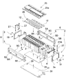
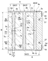
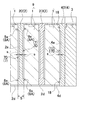
図1〜図7に、本発明の実施の形態に係る電源装置として、車載用の電源装置に適用した例を説明する。これらの図において、図1は電源装置の斜視図、図2は図1の電源装置を下側から見た分解斜視図、図3は図1の電源装置の分解斜視図、図4は電源装置の概略水平断面図、図5は電源装置の概略垂直断面図、図6は電池セル1とセパレータ2の斜視図、図7はセパレータ2の正面図をそれぞれ示している。   1 to 7, an example in which the power supply device according to the embodiment of the present invention is applied to an in-vehicle power supply device will be described. In these drawings, FIG. 1 is a perspective view of the power supply device, FIG. 2 is an exploded perspective view of the power supply device of FIG. 1 viewed from below, FIG. 3 is an exploded perspective view of the power supply device of FIG. 5 is a schematic vertical sectional view of the power supply device, FIG. 6 is a perspective view of the battery cell 1 and the separator 2, and FIG. 7 is a front view of the separator 2.

この電源装置は、主としてハイブリッド自動車や電気自動車等の電動車両に搭載されて、車両の走行モータに電力を供給して、車両を走行させる電源に使用される。ただ、本発明の電源装置は、ハイブリッド自動車や電気自動車以外の電動車両に使用でき、また電動車両以外の大出力が要求される用途、例えば蓄電装置用の電源としても使用できる。
(電源装置)
This power supply device is mainly mounted on an electric vehicle such as a hybrid vehicle or an electric vehicle, and is used as a power source for driving the vehicle by supplying electric power to a traveling motor of the vehicle. However, the power supply device of the present invention can be used for an electric vehicle other than a hybrid vehicle or an electric vehicle, and can also be used as a power source for a power storage device such as an electric vehicle requiring high output.
(Power supply)

図1〜図6に示す電源装置は、複数の電池セル1を積層してなる電池積層体9と、各電池セル1同士の間に配置された絶縁性を有するセパレータ2と、電池積層体9を積層方向に締結するための固定部材6とを備えている。図に示す電源装置は、電池積層体9を固定部材6で締結して電池ブロック11としている。
(電池セル1)
1 to 6 includes a battery laminate 9 formed by laminating a plurality of battery cells 1, an insulating separator 2 disposed between the battery cells 1, and a battery laminate 9. And a fixing member 6 for fastening them in the stacking direction. In the power supply device shown in the figure, the battery stack 9 is fastened by a fixing member 6 to form a battery block 11.
(Battery cell 1)

電池セル1は、図6に示すように、その外形を構成する外装缶1xを、厚さに比べて幅が広い、言い換えると幅よりも薄い角形としている。さらに、電池セル1は、角形で有底の外装缶1xの開口部を封口板1aで閉塞している。ここで、外装缶1xの外形を角形とする電池セル1は、有底の外装缶1xの底側の面となる底面1Dと、互いに積層される電池セル1同士の対向面となる、幅方向に広がる主面1Aと、電池積層体5の両側面を構成する面となる、電池セル1の厚さ方向に広がる外側面1Bと、外装缶1xの開口部を閉塞する封口板1aで構成される面となる天面1Cとを備えている。角形の電池セル1は、複数個が厚さ方向に積層されて電池積層体9を構成している。
なお、本明細書において、電池セル1の上下方向は、図面で示す方向、すなわち、外装缶1xの底側を下方向、封口板1a側を上方向とする。
As shown in FIG. 6, the battery cell 1 is configured such that the outer can 1x constituting the outer shape is wider than the thickness, in other words, a rectangular shape thinner than the width. Furthermore, the battery cell 1 has the opening part of the square-shaped bottomed outer can 1x closed with a sealing plate 1a. Here, the battery cell 1 having the outer shape of the outer can 1x as a square has a bottom surface 1D as a bottom surface of the bottomed outer can 1x and a facing surface between the battery cells 1 stacked on each other in the width direction. 1A, the outer surface 1B that extends in the thickness direction of the battery cell 1 and the sealing plate 1a that closes the opening of the outer can 1x. And a top surface 1C to be a surface. A plurality of prismatic battery cells 1 are stacked in the thickness direction to form a battery stack 9.
In this specification, the vertical direction of the battery cell 1 is the direction shown in the drawing, that is, the bottom side of the outer can 1x is the downward direction, and the sealing plate 1a side is the upward direction.

電池セル1は、リチウムイオン電池である。ただし、電池セル1は、ニッケル水素電池、ニッケルカドミウム電池等の充電可能な二次電池とすることもできる。電池セル1にリチウムイオン二次電池を使用する電源装置は、電池セル全体の体積や質量に対する充電容量を大きくできる特長がある。   The battery cell 1 is a lithium ion battery. However, the battery cell 1 can also be a rechargeable secondary battery such as a nickel metal hydride battery or a nickel cadmium battery. The power supply device using a lithium ion secondary battery for the battery cell 1 has a feature that the charge capacity with respect to the volume and mass of the entire battery cell can be increased.

さらに、電池セル1は、外装缶1xを閉塞する封口板1aの両端部に正負の電極端子1bを設けると共に、一対の電極端子1bの間に安全弁1cを設けている。安全弁1cは、外装缶1xの内圧が所定値以上に上昇した際に開弁して、内部のガスを放出できるように構成される。この電池セル1は、安全弁1cの開弁により、外装缶1xの内圧上昇を停止することができる。   Further, the battery cell 1 is provided with positive and negative electrode terminals 1b at both ends of the sealing plate 1a that closes the outer can 1x, and a safety valve 1c between the pair of electrode terminals 1b. The safety valve 1c is configured to open when the internal pressure of the outer can 1x rises to a predetermined value or more, and to release the internal gas. The battery cell 1 can stop the increase in the internal pressure of the outer can 1x by opening the safety valve 1c.

ここで、電池セル1は、外装缶を金属製としている。このため、隣接する電池セル1の外装缶同士が接触してショートするのを防止するために、各電池セル1の間に絶縁性のセパレータ2を介在させている。このように、セパレータ2で絶縁して積層される電池セル1は、外装缶をアルミニウムなどの金属製にできる。また、結露等による短絡を防止するために、外装缶を絶縁フィルムで覆ったり、外装缶を絶縁コーティングしたりする構成としても良い。この場合、電池セルの絶縁性をより高めて高い信頼性を実現できる。
(セパレータ2)
Here, the battery cell 1 has a metal outer can. For this reason, in order to prevent the outer cans of the adjacent battery cells 1 from coming into contact with each other and short-circuiting, an insulating separator 2 is interposed between the battery cells 1. Thus, the battery cell 1 insulated and stacked by the separator 2 can have an outer can made of metal such as aluminum. In order to prevent a short circuit due to condensation or the like, the outer can may be covered with an insulating film, or the outer can may be coated with an insulating coating. In this case, high reliability can be realized by further increasing the insulation of the battery cell.
(Separator 2)

セパレータ2は、互いに隣接する電池セル1を絶縁して積層するスペーサである。このセパレータ2はプラスチック等の絶縁材で製作されている。セパレータ2は、互いに隣接する電池セル1同士の間に介在されて、隣接する電池セル1を絶縁している。図のセパレータ2は、プラスチックを所定の形状に成形してなる成形体としている。このセパレータ2は、固定部材6により電池積層体9が両端から挟着されても破壊されない十分な強度に設計され、好ましくは耐熱性に優れたプラスチック製、例えば、ポリブチレンテレフタラート製とすることができる。ただ、セパレータは、ナイロン樹脂、エポキシ樹脂などのプラスチック製とすることもできる。   The separator 2 is a spacer that insulates and laminates battery cells 1 adjacent to each other. The separator 2 is made of an insulating material such as plastic. The separator 2 is interposed between the battery cells 1 adjacent to each other to insulate the adjacent battery cells 1. The separator 2 in the figure is a molded body formed by molding plastic into a predetermined shape. The separator 2 is designed to have sufficient strength so as not to be destroyed even when the battery stack 9 is sandwiched from both ends by the fixing member 6, and preferably made of a plastic excellent in heat resistance, for example, polybutylene terephthalate. Can do. However, the separator may be made of a plastic such as nylon resin or epoxy resin.

図6の斜視図と図7の正面図に示すセパレータ2は、電池セル1の主面1Aとほぼ等しい大きさの本体プレート部2aを備えており、この本体プレート部2aを互いに隣接する電池セル1の間に積層して、これらの電池セル1同士を絶縁している。さらに、セパレータ2は、対向して積層される電池セル1の膨張を吸収できるように、電池セル1の主面1Aと対向する対向面の中央部に穴部7を設けている。図に示すセパレータ2の穴部7は、中央部を凹状に窪ませた凹部7Aとしている。   The separator 2 shown in the perspective view of FIG. 6 and the front view of FIG. 7 includes a main body plate portion 2a having a size substantially equal to the main surface 1A of the battery cell 1, and the main body plate portion 2a is adjacent to the battery cell. The battery cells 1 are insulated from each other by being laminated between the two. Furthermore, the separator 2 is provided with a hole 7 at the center of the facing surface facing the main surface 1A of the battery cell 1 so as to absorb the expansion of the battery cell 1 stacked oppositely. The hole 7 of the separator 2 shown in the figure is a recess 7A having a recessed central portion.

なお、本明細書において、穴部とは、セパレータの表面よりも内部に向かって空隙を形成するように成形されたものであって、底板の有無を問わないものとする。すなわち、穴部とは、底板を有する凹部とすることも、底板のない貫通穴とすることも、部分的に底板を有する貫通穴とすることもできる。   In addition, in this specification, a hole part is shape | molded so that a space | gap may be formed inside rather than the surface of a separator, Comprising: The presence or absence of a bottom plate shall not be ask | required. That is, the hole can be a recess having a bottom plate, a through hole without a bottom plate, or a through hole partially having a bottom plate.

図4と図5に示すセパレータ2は、本体プレート部2aの中央部であって、両面に凹部7Aを設けている。各々の凹部7Aは、本体プレート部2aの両面に配置される電池セル1の主面1Aの中央部に対向して設けられている。ただ、詳細には後述するが、穴部7は、セパレータの中央部に貫通して設けた貫通穴とすることもできる。
なお、図4と図5においては、セパレータ2に設ける穴部7である凹部7Aの構造を理解しやすくするために、セパレータ2の厚さ、凹部7Aの形状や深さ等を誇張して表示している。
The separator 2 shown in FIGS. 4 and 5 is a central portion of the main body plate portion 2a, and is provided with concave portions 7A on both surfaces. Each concave portion 7A is provided to face the central portion of the main surface 1A of the battery cell 1 disposed on both surfaces of the main body plate portion 2a. However, as will be described later in detail, the hole 7 can be a through hole provided penetrating through the central portion of the separator.
4 and 5, the thickness of the separator 2, the shape and depth of the recess 7A, etc. are exaggerated for easy understanding of the structure of the recess 7A, which is the hole 7 provided in the separator 2. doing.

ここで、本体プレート部2aの中央部に凹部や貫通穴からなる穴部7を設けるのは、電池セル1の膨張を効果的に吸収するためである。電池セル1の膨張は、充放電を繰り返すことで発生するガスに起因する内圧の上昇により、あるいは外装缶1xに収納される電極板(図示せず)が膨張することによって生じる。このような電池セル1の膨張により、外装缶1xは厚さ方向に膨らむ状態となる。厚さ方向に膨らむ外装缶1xは、主面1Aの外周部に比べて中央部が撓みやすく、これにより主面1Aの中央部における膨張量が最も大きくなる。したがって、セパレータ2は、電池セル1の主面1Aと対向する対向面の中央部に凹部や貫通穴からなる穴部7を設けることで、効果的に電池セル1の膨張を吸収できる。   Here, the reason why the hole portion 7 including a concave portion and a through hole is provided in the central portion of the main body plate portion 2 a is to effectively absorb the expansion of the battery cell 1. The expansion of the battery cell 1 is caused by an increase in internal pressure caused by gas generated by repeated charge / discharge or by expansion of an electrode plate (not shown) housed in the outer can 1x. Due to the expansion of the battery cell 1, the outer can 1x is in a state of expanding in the thickness direction. The outer can 1x that swells in the thickness direction is more likely to bend at the center than the outer periphery of the main surface 1A, whereby the amount of expansion at the center of the main surface 1A is the largest. Therefore, the separator 2 can effectively absorb the expansion of the battery cell 1 by providing the hole portion 7 formed of a recess or a through hole in the central portion of the facing surface facing the main surface 1A of the battery cell 1.

さらに、膨張する電池セル1は、外装缶1xの主面1Aが外周部から中央部に向かって次第に膨らむ湾曲形状に膨張する。したがって、図4と図5に示すように、セパレータ2Aに設ける凹部7Aは、膨張する電池セル1の外装缶1xの表面に沿う形状となるように、好ましくは、外周部から中央部に向かって次第に深くなる湾曲形状に成形する。図に示すセパレータ2Aは、本体プレート部2aの中央部に設けた凹部7Aの断面形状を、中央凹となる湾曲面7aとしている。凹部7Aの内面を湾曲面7aとするセパレータ2Aは、電池セル1が膨張する状態において、中央凸に膨らむ外装缶1xの表面を凹部7Aの内面に密着させて、主面1Aの表面をより広い面積で均等に支持できる。   Furthermore, the battery cell 1 that expands expands into a curved shape in which the main surface 1A of the outer can 1x gradually expands from the outer periphery toward the center. Therefore, as shown in FIGS. 4 and 5, the recess 7 </ b> A provided in the separator 2 </ b> A is preferably from the outer peripheral portion toward the central portion so as to have a shape along the surface of the outer can 1 x of the expanding battery cell 1. Molded into a gradually deepened curved shape. In the separator 2A shown in the drawing, the cross-sectional shape of the concave portion 7A provided in the central portion of the main body plate portion 2a is a curved surface 7a that becomes the central concave portion. In the state where the battery cell 1 expands, the separator 2A having the inner surface of the recess 7A as the curved surface 7a allows the surface of the outer can 1x that swells in the center to be in close contact with the inner surface of the recess 7A so that the surface of the main surface 1A is wider. Can be supported evenly by area.

ただ、セパレータに設ける凹部は、断面形状を必ずしも湾曲面とする必要はなく、図8や図9に示す形状とすることもできる。図8に示すセパレータ2Bの凹部7Bは、中央部に向かって段階的に深くなる段差形状として中央凹の形状としている。さらに、図9に示すセパレータ2Cの凹部7Cは、中央部の底面7cを平面状とすると共に、この底面7cに向かって次第に傾斜する傾斜面7dを外周部に設けて中央凹の形状としている。さらに、セパレータの凹部は、必ずしも断面形状を中央凹とする必要はない。図10に示すセパレータ2Dは、均等な深さの溝型の凹部7Dを設けている。
なお、図8〜図10においても、セパレータ2に設ける凹部7B、7C、7Dの構造を理解しやすくするために、セパレータ2の厚さ、凹部7B、7C、7Dの形状や深さ等を誇張して表示している。
However, the concave portion provided in the separator does not necessarily have a curved surface in cross section, and may have a shape shown in FIGS. The concave portion 7B of the separator 2B shown in FIG. 8 has a central concave shape as a stepped shape that gradually increases toward the central portion. Further, the concave portion 7C of the separator 2C shown in FIG. 9 has a flat bottom surface 7c at the center, and an inclined surface 7d gradually inclined toward the bottom surface 7c on the outer peripheral portion so as to have a central concave shape. Furthermore, the recess of the separator is not necessarily required to have a central recess in cross-sectional shape. The separator 2D shown in FIG. 10 is provided with a groove-shaped recess 7D having an equal depth.
8 to 10 also exaggerate the thickness of the separator 2 and the shape and depth of the recesses 7B, 7C, and 7D so that the structure of the recesses 7B, 7C, and 7D provided in the separator 2 can be easily understood. Is displayed.

凹部7A、7B、7C、7Dの深さは、セパレータ2の本体プレート部2aの厚さや電池セル1の主面1Aの大きさ等によって最適な深さに設定される。本体プレート部を厚くしてなるセパレータは、凹部を深く成形しながら優れた強度を維持できる。また、主面を大きくしてなる電池セルを積層する構造においては、電池セルの膨張量が大きくなりやすいので、凹部を深く成形して電池セルの膨張をより効果的に吸収できる。凹部7A、7B、7C、7Dの最大深さ(s)、言い換えると、膨張していない状態の電池セル1の主面1Aとセパレータ2の凹部7A、7B、7C、7Dの内面との間にできる隙間の最大幅(s)は、セパレータ2の本体プレート部2aの厚さ(S)の3%〜20%、好ましくは5%〜10%とすることができる。例えば、本体プレート部2aの厚さ(S)を3〜5mmとするセパレータ2と、主面1Aの大きさを90mm×150mmとする電池セル1とを積層してなる電源装置においては、凹部7A、7B、7C、7Dの最大深さ(s)を、0.1mm〜0.5mm、好ましくは、0.2mm〜0.4mmとすることができる。   The depth of the recesses 7A, 7B, 7C, and 7D is set to an optimum depth depending on the thickness of the main body plate portion 2a of the separator 2, the size of the main surface 1A of the battery cell 1, and the like. The separator formed by thickening the main body plate portion can maintain excellent strength while forming the concave portion deeply. Further, in the structure in which the battery cells having a large main surface are stacked, the amount of expansion of the battery cells tends to increase, so that the recesses can be deeply formed to absorb the expansion of the battery cells more effectively. The maximum depth (s) of the recesses 7A, 7B, 7C, 7D, in other words, between the main surface 1A of the battery cell 1 in an unexpanded state and the inner surfaces of the recesses 7A, 7B, 7C, 7D of the separator 2 The maximum width (s) of the gap that can be made can be 3% to 20%, preferably 5% to 10% of the thickness (S) of the main body plate portion 2a of the separator 2. For example, in the power supply device in which the separator 2 having a thickness (S) of the main body plate portion 2a of 3 to 5 mm and the battery cell 1 having a main surface 1A of 90 mm × 150 mm are stacked, the recess 7A , 7B, 7C, 7D can have a maximum depth (s) of 0.1 mm to 0.5 mm, preferably 0.2 mm to 0.4 mm.

このようなセパレータ2を電池セル1同士の間に積層する電池積層体9において、例えば、本体プレート部2aの両面に設けた凹部7A、7B、7C、7Dの最大深さ(s)を0.3mmとする場合、1枚のセパレータ2で最大0.6mmの膨張を吸収できる。したがって、このセパレータ2を介して12個の電池セル1を積層してなる電池積層体9では、0.6mm×11=6.6mmとなり、電池セル1の積層方向における電池積層体9全体の膨張を6mm以上も吸収できる。このため、固定部材6、とくにバインドバー(詳細には後述する)にかかる負荷を低減して、電池セル1の膨張時におけるバインドバーに作用する引張力を低減して、バインドバーが破損する等の弊害を有効に防止できる。   In the battery stack 9 in which such separators 2 are stacked between the battery cells 1, for example, the maximum depth (s) of the recesses 7A, 7B, 7C, and 7D provided on both surfaces of the main body plate portion 2a is set to 0. In the case of 3 mm, a single separator 2 can absorb a maximum expansion of 0.6 mm. Therefore, in the battery laminate 9 in which twelve battery cells 1 are laminated via the separator 2, 0.6 mm × 11 = 6.6 mm, and the entire battery laminate 9 expands in the stacking direction of the battery cells 1. Can absorb 6 mm or more. For this reason, the load applied to the fixing member 6, particularly the bind bar (described later in detail) is reduced, the tensile force acting on the bind bar when the battery cell 1 is expanded is reduced, and the bind bar is damaged. Can be effectively prevented.

さらに、図11に示すセパレータ2Gは、対向して積層される電池セル1の膨張を吸収できるように、電池セル1の主面1Aと対向する対向面の中央部に穴部7として貫通穴7Gを開口している。このように、中央部に設ける穴部7を貫通穴7Gとするセパレータ2Gも、電池セル1が膨張する状態において、中央凸に膨らむ外装缶1xの表面を貫通穴7Gの内側に侵入させて、電池セル1の膨張を吸収する。このように、穴部7を貫通穴7Gとするセパレータ2Gは、電池セル1の膨張を、最大でセパレータ2Gの厚さに相当する量だけ吸収できる。言い換えると、セパレータ2Gを薄くしながら、吸収できる膨張量を大きくできる。ただ、セパレータに設ける穴部を貫通穴とする構造は、隣接する電池セルが膨張する状態で、貫通穴の内側において、隣接する電池セルの外装缶同士が接触するおそれがある。このとき、隣接する電池セルの外装缶に電圧差があると、接触する外装缶同士がショートがする。したがって、このような事態を阻止するために、電池セル1は、好ましくは、外装缶1xを絶縁フィルムで被覆し、あるいは外装缶1xを絶縁コーティングして絶縁構造とする。あるいは、図11の鎖線で示すように、貫通穴7Gの内側に絶縁シートまたは薄い絶縁プレート等の絶縁部材13を介在させてもよい。このような絶縁部材13には、セパレータ2Aに対して厚さの薄いものが使用される。   Furthermore, the separator 2G shown in FIG. 11 has a through hole 7G as a hole 7 at the center of the facing surface facing the main surface 1A of the battery cell 1 so as to absorb the expansion of the battery cell 1 stacked oppositely. Is open. In this way, the separator 2G having the through hole 7G as the hole 7 provided in the central part also allows the surface of the outer can 1x that swells to the center convex to enter the inside of the through hole 7G in a state where the battery cell 1 expands, The expansion of the battery cell 1 is absorbed. Thus, the separator 2G having the hole 7 as the through hole 7G can absorb the expansion of the battery cell 1 by an amount corresponding to the thickness of the separator 2G at the maximum. In other words, the amount of expansion that can be absorbed can be increased while making the separator 2G thinner. However, in the structure in which the hole provided in the separator is a through hole, the outer battery cans may be in contact with each other inside the through hole in a state where the adjacent battery cell expands. At this time, if there is a voltage difference between the outer cans of adjacent battery cells, the outer cans that are in contact with each other short-circuit. Therefore, in order to prevent such a situation, the battery cell 1 preferably has an insulating structure in which the outer can 1x is covered with an insulating film or the outer can 1x is insulatingly coated. Alternatively, as indicated by a chain line in FIG. 11, an insulating member 13 such as an insulating sheet or a thin insulating plate may be interposed inside the through hole 7G. As such an insulating member 13, a member having a thickness smaller than that of the separator 2A is used.

さらに、図4〜図7に示すセパレータ2は、電池セル1と対向する対向面の外周部を接合部8として、この接合部8を電池セル1の主面1Aの外周部に接合させている。接合部8の表面は、膨張しない状態における電池セル1の主面1Aに平行であって、互いに対向するセパレータ2と電池セル1とを積層して締結する状態では、電池セル1の主面1Aに密着するようにしている。ただ、接合部の表面は、主面に対して多少傾斜する傾斜面とすることもできる。   Furthermore, the separator 2 shown in FIGS. 4 to 7 has the outer peripheral portion of the facing surface facing the battery cell 1 as a joint portion 8, and this joint portion 8 is joined to the outer peripheral portion of the main surface 1 </ b> A of the battery cell 1. . The surface of the joint portion 8 is parallel to the main surface 1A of the battery cell 1 in a non-expanded state, and in the state where the separator 2 and the battery cell 1 facing each other are stacked and fastened, the main surface 1A of the battery cell 1 It is trying to adhere to. However, the surface of the joint portion may be an inclined surface that is slightly inclined with respect to the main surface.

図4〜図7に示すセパレータ2は、本体プレート部2aの中央部に凹部7Aを設けると共に、外周部に接合部8を設けている。図6と図7に示すセパレータ2は、本体プレート部2aの外周部に設けた接合部8Aを、電池セル1の主面1Aの4辺に沿う枠形状としている。図に示す接合部8Aは、主面1Aの上下の端部、すなわち、外装缶1xの底面側と封口板1a側の端部に沿う帯状の水平接合部8aと、主面1Aの左右の端部、すなわち、外装缶1xの両側面側の端部に沿う帯状の垂直接合部8bとからなる。この形状のセパレータ2は、枠形状の接合部8Aを電池セル1の主面1Aの外周部に接合させて、電池積層体9を構成する複数の電池セル1を確実に、しかも強固に締結できる。   The separator 2 shown in FIGS. 4 to 7 is provided with a concave portion 7A in the central portion of the main body plate portion 2a and a joint portion 8 on the outer peripheral portion. In the separator 2 shown in FIGS. 6 and 7, the joining portion 8 </ b> A provided on the outer peripheral portion of the main body plate portion 2 a has a frame shape along the four sides of the main surface 1 </ b> A of the battery cell 1. The joining portion 8A shown in the figure includes upper and lower ends of the main surface 1A, that is, strip-like horizontal joining portions 8a along the bottom surface side of the outer can 1x and the end portion on the sealing plate 1a side, and left and right ends of the main surface 1A. Part, that is, a belt-like vertical joint portion 8b along end portions on both sides of the outer can 1x. The separator 2 having this shape can securely and firmly fasten the plurality of battery cells 1 constituting the battery stack 9 by joining the frame-shaped joint portion 8A to the outer peripheral portion of the main surface 1A of the battery cell 1. .

ここで、図4〜図7に示すセパレータ2Aは、電池セル1の主面1Aの外周部に沿う枠形状の接合部8Aを設けているが、この接合部8Aは、本体プレート部2aの外周縁まで延長して設けていない。図のセパレータ2Aは、電池セル1の主面1Aの外周部と対向する部分であるが、外周縁に沿う部分を除く領域に接合部8Aを設けている。図のセパレータ2Aは、詳細には後述するが、電池セル1の封口部分(図において上端部)と対向する部分、及び電池セル1の外周縁と対向する部分に沿う部分には接合部8Aよりも薄く形成してなる薄肉部14を設けている。ただ、セパレータは、図8〜図10に示すように、本体プレート部2aの外周縁まで延長して接合部8Aを設けることもできる。   Here, the separator 2A shown in FIGS. 4 to 7 is provided with a frame-shaped joint portion 8A along the outer peripheral portion of the main surface 1A of the battery cell 1, and this joint portion 8A is formed outside the main body plate portion 2a. It does not extend to the periphery. The separator 2 </ b> A in the figure is a portion facing the outer peripheral portion of the main surface 1 </ b> A of the battery cell 1, but a joining portion 8 </ b> A is provided in a region excluding the portion along the outer peripheral edge. The separator 2A in the figure will be described in detail later, but the joint portion 8A is connected to the portion facing the sealing portion (upper end portion in the figure) of the battery cell 1 and the portion facing the outer peripheral edge of the battery cell 1. The thin-walled portion 14 is also formed. However, as shown in FIGS. 8 to 10, the separator can be extended to the outer peripheral edge of the main body plate portion 2 a to provide the joint portion 8 </ b> A.

図6と図7に示すセパレータ2は、本体プレート部2aの上下の端部に位置する水平接合部8aの幅(w1)を電池セル1の上下方向の高さ(H)の5%〜15%、好ましくは8%〜12%とすると共に、枠形状の接合部8Aの左右に位置する垂直接合部8bの幅(w2)を電池セル1の左右の横幅(W)の5%〜20%、好ましくは8%〜15%としている。このセパレータ2は、本体プレート部2a全体に対する、凹部7Aの面積の割合を50%〜90%、好ましくは60%〜80%とすることができる。接合部8の面積を広くしてなるセパレータ2は、電池積層体9を構成する複数の電池セル1をより広い面積で押圧状態に支持して確実に締結できる。   The separator 2 shown in FIGS. 6 and 7 has a width (w1) of the horizontal joint portion 8a located at the upper and lower ends of the main body plate portion 2a that is 5% to 15% of the height (H) of the battery cell 1 in the vertical direction. %, Preferably 8% to 12%, and the width (w2) of the vertical joint 8b located on the left and right of the frame-shaped joint 8A is 5% to 20% of the lateral width (W) of the battery cell 1 Preferably, the content is 8% to 15%. In the separator 2, the ratio of the area of the recess 7A to the entire body plate portion 2a can be 50% to 90%, preferably 60% to 80%. The separator 2 having a large area of the joint portion 8 can securely fasten the plurality of battery cells 1 constituting the battery stack 9 in a pressed state with a wider area.

さらに、図12に示すセパレータ2Eは、本体プレート部2aに設けた接合部8Bを、電池セル1の主面1Aの上下の端部、すなわち、外装缶1xの底面側と封口板1a側の端部に沿う帯状としている。このセパレータ2Eも、本体プレート部2aの上下の端部に設けた接合部8Bの幅(w1)を電池セル1の上下方向の高さ(H)の5%〜15%、好ましくは8%〜12%とすることができる。さらに、このセパレータ2Eは、垂直断面形状を中央凹の湾曲面7eとする凹部7Eを、本体プレート部2aの両側縁まで延長して設けている。このセパレータ2Eは、本体プレート部2aを湾曲しやすくして、膨張する電池セル1の表面を凹部7Eの内面に密着できる。この形状のセパレータ2Eは、上下の接合部8Bを電池セル1の主面1Aの上下の端縁部に接合させて、電池積層体9を構成する複数の電池セル2を確実に締結できる。   Further, the separator 2E shown in FIG. 12 has a joint portion 8B provided on the main body plate portion 2a at the upper and lower end portions of the main surface 1A of the battery cell 1, that is, the end portions on the bottom surface side and the sealing plate 1a side of the outer can 1x. It is in the shape of a belt along the part. Also in this separator 2E, the width (w1) of the joint portion 8B provided at the upper and lower ends of the main body plate portion 2a is 5% to 15%, preferably 8% to the vertical height (H) of the battery cell 1. It can be 12%. Further, the separator 2E is provided with recesses 7E having a vertical sectional shape with a curved surface 7e having a central recess extending to both side edges of the main body plate portion 2a. This separator 2E makes it easy to bend the main body plate portion 2a, so that the surface of the expanding battery cell 1 can be in close contact with the inner surface of the recess 7E. The separator 2E having this shape can securely fasten the plurality of battery cells 2 constituting the battery stack 9 by joining the upper and lower joint portions 8B to the upper and lower edge portions of the main surface 1A of the battery cell 1.

さらに、図4〜図7、及び図11に示すセパレータ2A、2Gは、電池セル1に挟まれる本体プレート部2aの端縁部であって、電池セル1の封口部分である上端部と対向する部分に沿って、接合部8よりも薄く形成している薄肉部14を設けている。セパレータ2は、好ましくは、図7に示すように、電池セル1の主面の外周縁部と対向する部分に沿って薄肉部14を設けている。図のセパレータ2A、2Gは、接合部8と薄肉部14とを段差状に形成して、薄肉部14を接合部8よりも薄くしている。ただ、薄肉部は、電池セルの外周縁に向かって次第に薄く成形し、あるいは、階段状に薄くすることもできる。また、薄肉部と接合部の境界部分を所定の曲率半径で折曲加工し、あるいは、傾斜する形状とすることもできる。図のセパレータ2A、2Gは、本体プレート部2aの両面に薄肉部14を設けている。この構造は、電池セル1の外周縁部に応力が集中するのをバランスよく防止できる。ただ、セパレータは、本体プレート部の片面にのみ薄肉部を設けることもできる。   Furthermore, separators 2 </ b> A and 2 </ b> G shown in FIGS. 4 to 7 and FIG. 11 are edge portions of the main body plate portion 2 a sandwiched between the battery cells 1, and are opposed to an upper end portion that is a sealing portion of the battery cells 1. A thin-walled portion 14 formed thinner than the joint portion 8 is provided along the portion. As shown in FIG. 7, the separator 2 is preferably provided with a thin portion 14 along a portion facing the outer peripheral edge portion of the main surface of the battery cell 1. The separators 2 </ b> A and 2 </ b> G shown in the figure have the joint 8 and the thin portion 14 formed in a stepped shape so that the thin portion 14 is thinner than the joint 8. However, the thin-walled portion can be gradually thinned toward the outer peripheral edge of the battery cell, or can be thinned stepwise. Moreover, the boundary part of a thin part and a junction part can also be bent by the predetermined curvature radius, or can also be made into the shape which inclines. In the illustrated separators 2A and 2G, thin portions 14 are provided on both surfaces of the main body plate portion 2a. This structure can prevent stress from being concentrated on the outer peripheral edge of the battery cell 1 in a well-balanced manner. However, a separator can also provide a thin part only in the single side | surface of a main-body plate part.

このように、電池セル1の封口部分に対向して薄肉部14を設ける構造は、複数の電池セル1とセパレータ2とを積層して、その両端面から強く挟着するときに、電池セル1の封口部分に対向して設けた薄肉部14によって、電池セル1の表面が強く押圧されるのを防止して、電池セル1の上端部に応力が集中するのを防止できる。とくに、角形の電池セル1は、外装缶1xの上端部に開口部を設けて、この開口部に封口板1aをレーザー溶接して密閉していることから、電池積層体9を両側から強く締結する状態では、電池セル1の上端部が局部的にセパレータ2に接触して、この部分に応力が集中しやすくなる。さらに、電池セル1の上端部は、内側に板状の封口板1aがあって圧縮しても薄く変形しないことから、この部分をセパレータ2で強圧すると、圧力がこの領域に集中して他の領域に分散できず、局部的に極めて大きな応力が発生して電池セル1を破損させる原因にもなる。したがって、このように、電池セル1の封口部分と対向する端縁部に薄肉部14を設けることによって、セパレータ2が電池セル1の上端部を強圧して電池セル1の上端側に応力が集中するのを回避して、電池セル1の封口部分のエッジの破損や変形を防止できる。   As described above, the structure in which the thin portion 14 is provided so as to face the sealing portion of the battery cell 1 is obtained when the plurality of battery cells 1 and the separator 2 are stacked and strongly sandwiched from both end faces. The thin-walled portion 14 provided to face the sealing portion of the battery cell 1 can prevent the surface of the battery cell 1 from being strongly pressed and can prevent stress from being concentrated on the upper end portion of the battery cell 1. In particular, the rectangular battery cell 1 is provided with an opening at the upper end of the outer can 1x, and the sealing plate 1a is laser-welded to the opening to seal the battery stack 9 from both sides. In this state, the upper end portion of the battery cell 1 is in contact with the separator 2 locally, and stress tends to concentrate on this portion. Furthermore, since the upper end portion of the battery cell 1 has a plate-like sealing plate 1a on the inside and does not deform thinly even when compressed, if this portion is strongly pressed with the separator 2, the pressure is concentrated in this region and other parts are It cannot disperse | distribute to an area | region, A very big stress generate | occur | produces locally, and also causes the battery cell 1 to be damaged. Therefore, by providing the thin portion 14 at the edge portion facing the sealing portion of the battery cell 1 in this manner, the separator 2 strongly pressurizes the upper end portion of the battery cell 1 and stress is concentrated on the upper end side of the battery cell 1. By avoiding this, breakage and deformation of the edge of the sealing portion of the battery cell 1 can be prevented.

また、電池セル1の主面1Aの外周縁部と対向する部分に沿って薄肉部14を設ける構造は、複数の電池セル1とセパレータ2とを積層して、その両端面から強く挟着するときに、電池セルの外周縁部に応力が集中するのを防止できる。とくに、電池セル1の主面1Aの外周縁のうち、封口部分を除く3辺は、外装缶1xの側面や底面が連結された部分であって、圧縮しても薄く変形しないことから、この部分をセパレータ2で強圧すると、押圧力がこの領域に集中して大きな応力が発生して外装缶1xを破損させたり変形させる原因となる。したがって、このように、電池セル1の主面1Aの外周縁部と対向する部分に薄肉部14を設けることによって、セパレータ2が電池セル1の外周部を強圧して電池セル1の外周部に応力が集中するのを回避して、電池セル1の外周部の破損や変形を防止できる。   Moreover, the structure which provides the thin part 14 along the part facing the outer-periphery edge part of 1 A of main surfaces of the battery cell 1 laminates | stacks the several battery cell 1 and the separator 2, and clamps firmly from the both end surfaces. Sometimes, stress can be prevented from concentrating on the outer peripheral edge of the battery cell. In particular, of the outer peripheral edge of the main surface 1A of the battery cell 1, the three sides excluding the sealing portion are portions where the side surface and bottom surface of the outer can 1x are connected, and are not deformed thinly even when compressed. When the portion is strongly pressed by the separator 2, the pressing force is concentrated on this region, and a large stress is generated, which causes the outer can 1x to be damaged or deformed. Therefore, by providing the thin-walled portion 14 in the portion facing the outer peripheral edge portion of the main surface 1A of the battery cell 1 in this way, the separator 2 strongly pressurizes the outer peripheral portion of the battery cell 1 to the outer peripheral portion of the battery cell 1. It is possible to avoid stress concentration and prevent damage and deformation of the outer peripheral portion of the battery cell 1.

以上のように、本体プレート部2aの外周縁に沿って設けられる薄肉部14は、例えば、主面1Aの大きさを90mm×150mmとする電池セル1を積層するセパレータ2においては、図7に示すように、電池セル1の上端部に沿う薄肉部14の幅(h1)を約7mm、電池セル1の底面に沿う薄肉部14の幅(h2)を約6mm、電池セル1の両側に対向して配置する薄肉部14の幅(h3)を約10mmとし、図5に示すように、薄肉部14の厚さ(d)を接合部8の厚さ(S)よりも0.3mm薄くする。ただし、薄肉部14の幅(h)は、たとえば2mm〜25mmとし、好ましくは3mm〜20mmとし、さらに好ましくは4mm〜15mmとすることができる。さらに、薄肉部14は、その平均厚さ(d)と、接合部8の厚さ(S)との差を、たとえば0.1mm〜1mmとし、好ましくは0.2mm〜0.8mmとし、さらに好ましくは0.3mm〜0.5mmとすることができる。   As described above, the thin-walled portion 14 provided along the outer peripheral edge of the main body plate portion 2a is, for example, in the separator 2 in which the battery cells 1 having the main surface 1A of 90 mm × 150 mm are stacked in FIG. As shown, the width (h1) of the thin portion 14 along the upper end of the battery cell 1 is about 7 mm, the width (h2) of the thin portion 14 along the bottom surface of the battery cell 1 is about 6 mm, and faces both sides of the battery cell 1. The width (h3) of the thin-walled portion 14 to be arranged is about 10 mm, and the thickness (d) of the thin-walled portion 14 is made 0.3 mm thinner than the thickness (S) of the joint 8 as shown in FIG. . However, the width (h) of the thin portion 14 is, for example, 2 mm to 25 mm, preferably 3 mm to 20 mm, and more preferably 4 mm to 15 mm. Furthermore, the thin-walled portion 14 has a difference between the average thickness (d) and the thickness (S) of the joined portion 8 of, for example, 0.1 mm to 1 mm, preferably 0.2 mm to 0.8 mm. Preferably it can be 0.3 mm-0.5 mm.

さらに、図6、図7、及び図12に示すセパレータ2は、本体プレート部2aの両面に、電池セル1を収納する収納部2xを形成している。この収納部2xは、電池セル1を定位置に嵌着できる形状として、隣接する電池セル1の位置ずれを阻止している。図のセパレータ2は、本体プレート部2aの外周縁に沿って、電池セル1の側面1Bを被覆する側壁2bと、電池セル1の天面1Cの一部を被覆する天面板2cと、電池セル1の底面1Dの両端部を被覆する突出片2dとを一体成形して設けている。このセパレータ2は、2枚のセパレータ2で電池セル1を挟み込んで、電池セル1の側面1Bを被覆している。このため、側壁2bは電池セル1の側面1Bとほぼ同じ大きさとしつつ、側壁2bのほぼ中央に本体プレート部2aを固定することで、各収納部2xにおいては、側壁2bの半分を使って電池セル1の側面1Bの約1/2を被覆している。また、収納部2xの上面は、天面板2cで電池セル1の封口板1aを部分的に覆いつつ、電極端子1bや安全弁1cを露出させるように、隣接する電池セル1同士の界面の上部を被覆している。一方で、収納部2xの底面側においては、電池セル1の底面1Dを露出させる開口部2yを設けている。図2、図6、及び図12のセパレータ2は、電池セル1の底面1Dの両端部を被覆する突出片2dを、側壁2bの下端に連結して設けており、一対の突出片2dの間の部分を開口部2yとして電池セル1の底面1Dを露出させている。セパレータ2の下端に設けられる突出片2dは、収納部2xに嵌着される電池セル1の下端のコーナー部を定位置に保持すると共に、後述する冷却プレート31と電池セル1との間に介在されて、電池セル1を冷却プレート31から絶縁している。   Furthermore, the separator 2 shown in FIGS. 6, 7, and 12 forms storage portions 2 x that store the battery cells 1 on both surfaces of the main body plate portion 2 a. The storage portion 2x has a shape that allows the battery cell 1 to be fitted in a fixed position, and prevents the adjacent battery cell 1 from being displaced. The separator 2 in the figure includes a side wall 2b covering the side surface 1B of the battery cell 1, a top plate 2c covering a part of the top surface 1C of the battery cell 1, and a battery cell along the outer peripheral edge of the main body plate portion 2a. Projecting pieces 2d that cover both ends of the bottom surface 1D of 1 are integrally formed. The separator 2 sandwiches the battery cell 1 between the two separators 2 and covers the side surface 1B of the battery cell 1. For this reason, the side wall 2b is approximately the same size as the side surface 1B of the battery cell 1, and the main body plate portion 2a is fixed at substantially the center of the side wall 2b, so that each storage portion 2x uses half of the side wall 2b. About 1/2 of the side surface 1B of the cell 1 is covered. In addition, the upper surface of the storage portion 2x covers the upper part of the interface between adjacent battery cells 1 so that the electrode terminal 1b and the safety valve 1c are exposed while partially covering the sealing plate 1a of the battery cell 1 with the top plate 2c. It is covered. On the other hand, an opening 2y that exposes the bottom surface 1D of the battery cell 1 is provided on the bottom surface side of the storage portion 2x. The separator 2 in FIGS. 2, 6 and 12 is provided with protruding pieces 2d covering both ends of the bottom surface 1D of the battery cell 1 connected to the lower ends of the side walls 2b, and between the pair of protruding pieces 2d. The bottom surface 1D of the battery cell 1 is exposed with this portion as the opening 2y. The protruding piece 2d provided at the lower end of the separator 2 holds the corner portion at the lower end of the battery cell 1 fitted in the storage portion 2x in a fixed position, and is interposed between the cooling plate 31 and the battery cell 1 described later. Thus, the battery cell 1 is insulated from the cooling plate 31.

以上のセパレータ2は、本体プレート部2aに、側壁2bと天面板2cと突出片2dとを一体成形して収納部2xを設けている。ただ、セパレータは、必ずしも側壁や天面板や突出片を設ける必要はなく、また、収納部を設ける必要もない。側壁や天面板や突出片を設けていないセパレータは、後述するように、全体の形状を本体プレート部からなる板状として、電池セルの間に積層することができる。また、セパレータは、本体プレート部に側壁のみを設け、あるいは天面板のみを設けることもできる。さらにまた、セパレータは、本体プレート部の外周縁の一部に側壁や天面板を設けて、電池セルを定位置に配置する位置決部材とすることもできる。   In the separator 2 described above, the side wall 2b, the top plate 2c, and the protruding piece 2d are integrally formed on the main body plate portion 2a to provide the storage portion 2x. However, the separator does not necessarily need to be provided with a side wall, a top plate, or a protruding piece, and it is not necessary to provide a storage portion. As will be described later, the separator that is not provided with the side wall, the top plate, or the protruding piece can be laminated between the battery cells as a whole plate-like plate shape. In addition, the separator can be provided with only the side wall or only the top plate in the main body plate portion. Furthermore, the separator can be a positioning member that is provided with a side wall or a top plate on a part of the outer peripheral edge of the main body plate portion and arranges the battery cells at a fixed position.

全体の形状を板状とし、あるいはシート状とするセパレータ2の例を、図13〜図18に示す。ここで、図13〜図15は、全体を板状とするセパレータ2F、2Hを示し、図16〜図18は、全体をシート状とするセパレータ2Iを示している。これらのセパレータ2F、2H、2Iも、図13、図15、図16、及び図18に示すように、電池セル1の間に介在される状態で積層される。これらのセパレータ2F、2H、2Iもプラスチック等の絶縁材で製作されており、互いに隣接する電池セル1同士の間に介在されて、隣接する電池セル1を絶縁している。   Examples of the separator 2 having a plate shape or a sheet shape as a whole are shown in FIGS. Here, FIGS. 13 to 15 show separators 2F and 2H having a plate shape as a whole, and FIGS. 16 to 18 show a separator 2I having a sheet shape as a whole. These separators 2F, 2H, and 2I are also laminated in a state of being interposed between the battery cells 1 as shown in FIGS. 13, 15, 16, and 18. These separators 2F, 2H, and 2I are also made of an insulating material such as plastic, and are interposed between adjacent battery cells 1 to insulate adjacent battery cells 1.

図13に示すセパレータ2Fは、プラスチックを板状に成形したものである。板状のセパレータ2Fは、電池セル1の主面1Aとほぼ等しい外形の四角形状としている。図のセパレータ2Fは、対向して積層される電池セル1の膨張を吸収できるように、電池セル1の主面1Aと対向する対向面の中央部に四角形状の穴部7を設けている。図に示すセパレータ2Fの穴部7は、中央部を凹状に窪ませた凹部7Fとしている。図に示す中央凹の凹部7Fは、底面7fを両側縁から中央部に向かって次第に深くなる傾斜面としている。さらに、図に示すセパレータ2Fは、電池セル1と対向する対向面の外周部を接合部8として、この接合部8を電池セル1の主面1Aの外周部に接合させている。図に示す接合部8は、電池セル1の外形に沿う長方形の枠形状としている。このセパレータ2Fは、両面に配置される電池セル1の主面1Aの中央部に対向して、両面に凹部7Fを設けている。   A separator 2F shown in FIG. 13 is formed by molding a plastic into a plate shape. The plate-like separator 2 </ b> F has a quadrangular shape having an outer shape substantially equal to the main surface 1 </ b> A of the battery cell 1. In the illustrated separator 2F, a rectangular hole 7 is provided in the central portion of the facing surface facing the main surface 1A of the battery cell 1 so as to absorb the expansion of the battery cells 1 stacked facing each other. The hole 7 of the separator 2F shown in the figure is a concave portion 7F having a concave central portion. The center concave recess 7F shown in the figure has a bottom surface 7f as an inclined surface that gradually becomes deeper from both side edges toward the center. Further, in the separator 2F shown in the figure, the outer peripheral portion of the facing surface facing the battery cell 1 is used as a joint portion 8, and the joint portion 8 is joined to the outer peripheral portion of the main surface 1A of the battery cell 1. The joining portion 8 shown in the figure has a rectangular frame shape that follows the outer shape of the battery cell 1. The separator 2F is provided with a concave portion 7F on both surfaces so as to face the central portion of the main surface 1A of the battery cell 1 arranged on both surfaces.

図14と図15に示すセパレータ2Hは、プラスチックを板状に成形したもので、電池セル1の主面1Aとほぼ等しい外形の四角形状とすると共に、電池セル1の主面1Aと対向する対向面の中央部に穴部7として貫通穴7Hを開口している。さらに、図に示すセパレータ2Hは、電池セル1と対向する対向面の外周部を接合部8として、この接合部8を電池セル1の主面1Aの外周部に接合させている。図に示す接合部8は、電池セルの外形に沿う四角形の枠形状であって、コーナー部を湾曲させてなる長方形のリング状としている。さらに、図に示す穴部7は、外周部であって接合部8との境界部分に、接合部8から貫通穴7Hに向かって次第に薄くなる絞り部7Xを設けている。図に示す絞り部7Xは、接合部8の内周に沿うと共に、貫通穴7Hの外周に沿う四角形のリング状で、接合部8の内周縁から貫通穴7Hの開口縁に向かって次第に薄くなる形状としている。図15に示す絞り部7Xは、表面を湾曲面7xとして内側に向かって次第に薄くしている。ただ、絞り部は、内側に向かって次第に薄くなる傾斜面とすることもできる。このように、貫通穴7Hの外周部に絞り部7Xを備える穴部7は、膨張によって中央凸に膨張する電池セル1の外装缶1xを絞り部7Xの表面に沿う状態で配置できる。さらに、図に示すセパレータ2Hは、電池セル1の封口部分を含む外周縁部と対向する部分に沿って、接合部8よりも薄く形成してなる薄肉部14を設けている。図のセパレータ2Hは、接合部8と薄肉部14とを段差状に形成して、薄肉部14を接合部8よりも薄くしている。   The separator 2H shown in FIG. 14 and FIG. 15 is formed by molding plastic into a plate shape, has a quadrangular shape that is substantially the same as the main surface 1A of the battery cell 1, and is opposed to the main surface 1A of the battery cell 1. A through hole 7H is opened as a hole 7 in the center of the surface. Further, in the separator 2H shown in the figure, the outer peripheral portion of the facing surface facing the battery cell 1 is used as a joint portion 8, and the joint portion 8 is joined to the outer peripheral portion of the main surface 1A of the battery cell 1. The joining portion 8 shown in the figure has a rectangular frame shape that follows the outer shape of the battery cell, and has a rectangular ring shape with curved corner portions. Further, the hole portion 7 shown in the drawing is provided with a narrowed portion 7X that gradually becomes thinner from the joint portion 8 toward the through hole 7H at the boundary portion with the joint portion 8 on the outer peripheral portion. The narrowed portion 7X shown in the drawing is a quadrangular ring shape along the inner periphery of the joint portion 8 and along the outer periphery of the through hole 7H, and gradually becomes thinner from the inner peripheral edge of the joint portion 8 toward the opening edge of the through hole 7H. It has a shape. The diaphragm portion 7X shown in FIG. 15 has a curved surface 7x and is gradually made thinner toward the inside. However, the narrowed portion can be an inclined surface that becomes gradually thinner toward the inside. As described above, the hole portion 7 including the throttle portion 7X on the outer peripheral portion of the through hole 7H can arrange the outer can 1x of the battery cell 1 that expands to the central convexity by expansion along the surface of the throttle portion 7X. Furthermore, the separator 2H shown in the drawing is provided with a thin portion 14 formed thinner than the joint portion 8 along a portion facing the outer peripheral edge portion including the sealing portion of the battery cell 1. In the illustrated separator 2 </ b> H, the joint portion 8 and the thin portion 14 are formed in a stepped shape so that the thin portion 14 is thinner than the joint portion 8.

さらに、図16〜図18に示すセパレータ2Iは、プラスチックをシート状に成形したものである。図に示すセパレータ2Iは、全体の形状を電池セル1の外形に沿う四角形の枠形状であって、コーナー部を湾曲させてなる長方形のリング状としている。図のセパレータ2Iは、電池セル1の主面1Aと対向する対向面の中央部に穴部7として貫通穴7Iを開口している。さらに、図に示すセパレータ2Iは、電池セル1と対向する対向面を接合部8Aとして、この接合部8Aを電池セル1の主面1Aの外周部に接合させている。このようなシート状のセパレータ2Iは、複数枚を積層して厚さを調整することができる。ただ、このセパレータも、プラスチックを板状に成形して製造することができる。   Furthermore, the separator 2I shown in FIGS. 16 to 18 is made by molding a plastic into a sheet shape. The separator 2I shown in the figure has a rectangular frame shape that conforms to the outer shape of the battery cell 1 as a whole, and has a rectangular ring shape with curved corner portions. The separator 2 </ b> I in the figure has a through hole 7 </ b> I as a hole 7 at the center of the facing surface that faces the main surface 1 </ b> A of the battery cell 1. Furthermore, the separator 2I shown in the drawing has the facing surface facing the battery cell 1 as a joint 8A, and the joint 8A is joined to the outer peripheral portion of the main surface 1A of the battery cell 1. Such a sheet-like separator 2I can be laminated to adjust the thickness. However, this separator can also be manufactured by molding plastic into a plate shape.

さらに、このセパレータ2Iは、図17に示すように、電池セル1の外形に沿う四角形状とするが、電池セル1の主面よりも小さな外形としている。このセパレータ2Iは、図18に示すように、隣接する電池セル1の間に介在される状態で、外周縁の外側に、隣接する電池セル1同士が接触しない非接合部16を形成している。このように、セパレータ2Iの外形を電池セル1の外形よりも小さくして、セパレータ2Iの外側に、隣接する電池セル同士が接触しない非接合部16を設ける構造は、前述の薄肉部14と同様に、複数の電池セル1とセパレータ2Iとを積層して、その両端面から強く挟着するときに、セパレータ2Iの外側に形成された非接合部16によって、隣接する電池セル1の外周縁部同士が強く押圧されるのを防止できる。このため、電池セル1の外周縁部が強く押圧されて応力が集中するのを回避して、電池セル1の外周部が破損したり変形するのを防止できる。   Furthermore, as shown in FIG. 17, the separator 2 </ b> I has a quadrangular shape that follows the outer shape of the battery cell 1, but has an outer shape smaller than the main surface of the battery cell 1. As shown in FIG. 18, the separator 2 </ b> I is formed between the adjacent battery cells 1, and forms a non-joining portion 16 where the adjacent battery cells 1 do not contact each other outside the outer peripheral edge. . As described above, the structure in which the outer shape of the separator 2I is made smaller than the outer shape of the battery cell 1 and the non-joining portion 16 where the adjacent battery cells do not contact each other is provided outside the separator 2I is the same as the thin-walled portion 14 described above. In addition, when the plurality of battery cells 1 and the separator 2I are stacked and strongly sandwiched from both end faces, the outer peripheral edge portion of the adjacent battery cell 1 is formed by the non-joining portion 16 formed outside the separator 2I. It can prevent that each other is pressed strongly. For this reason, it can avoid that the outer peripheral part of the battery cell 1 is strongly pressed and stress concentrates, and it can prevent that the outer peripheral part of the battery cell 1 is damaged or deform | transformed.

以上のように、全体を板状やシート状とするセパレータ2F、2H、2Iは、接着材や接着テープ等で貼着して電池セル1の主面1Aの定位置に固定することができる。このように、全体を板状やシート状とするセパレータ2F、2H、2Iは、厚さを薄くできるので、複数の電池セル1の間に介在させて積層した状態で電池積層体の全長を短くして全体をコンパクトにできる。   As described above, the separators 2F, 2H, and 2I having a plate shape or a sheet shape as a whole can be fixed to a fixed position on the main surface 1A of the battery cell 1 by being attached with an adhesive or an adhesive tape. As described above, the separators 2F, 2H, and 2I having a plate shape or a sheet shape as a whole can be reduced in thickness, so that the overall length of the battery stack can be shortened in a state of being laminated between the plurality of battery cells 1. The whole can be made compact.

(電池積層体9)
電池積層体9は、複数の電池セル1とセパレータ2とを交互に積層している。この電池積層体9は、互いに隣接する電池セル1の間に、絶縁性を有するセパレータ2を介在する状態で積層して、隣接する電池セル1同士をセパレータ2で絶縁している。積層されて電池積層体9を構成する複数の電池セル1は、正負の電極端子1bを接続して互いに直列及び/又は並列に接続される。電池積層体9は、隣接する電池セル1の正負の電極端子1bを、バスバー12を介して互いに直列及び/又は並列に接続する。電池積層体は、隣接する電池セルを互いに直列に接続して出力電圧を高くでき、隣接する電池セルを並列に接続して充放電の電流を大きくできる。
(Battery laminate 9)
The battery stack 9 has a plurality of battery cells 1 and separators 2 stacked alternately. The battery stack 9 is stacked with battery separators 1 adjacent to each other with an insulating separator 2 interposed therebetween, and the adjacent battery cells 1 are insulated from each other by the separator 2. The plurality of battery cells 1 that are stacked to form the battery stack 9 are connected in series and / or in parallel with each other by connecting positive and negative electrode terminals 1b. The battery stack 9 connects positive and negative electrode terminals 1 b of adjacent battery cells 1 to each other in series and / or in parallel via a bus bar 12. The battery stack can increase the output voltage by connecting adjacent battery cells in series with each other, and can increase the charge / discharge current by connecting adjacent battery cells in parallel.

図3に示す電池ブロック11は、12個の電池セル1を2並6直に接続している。隣接する電池セル1同士を並列に接続し、並列接続された電池セル1を互いに直列に接続する電池ブロック11は、出力電流を大きくしながら、出力電圧を高くして出力を大きくできる。ただ、本発明は、電池積層体を構成する電池セルの個数とその接続状態を特定しない。電池ブロックは、並列と直列に接続する電池セルの個数を種々に変更することができ、あるいは全ての電池セルを直列に接続することも並列に接続することもできる。   The battery block 11 shown in FIG. 3 connects 12 battery cells 1 in two rows and six straight lines. The battery blocks 11 that connect adjacent battery cells 1 in parallel and connect the battery cells 1 connected in parallel to each other in series can increase the output voltage and increase the output while increasing the output current. However, the present invention does not specify the number of battery cells constituting the battery stack and the connection state thereof. In the battery block, the number of battery cells connected in parallel and in series can be changed variously, or all the battery cells can be connected in series or connected in parallel.

さらに、図の電源装置は、電池積層体9の両端に配置される電池セル1の外側に、エンドセパレータ4を介して、固定部材6を構成するエンドプレート3を配置している。この構造は、エンドプレート3を金属製としながら、外装缶1xを金属製とする電池セル1を、絶縁性を有するエンドセパレータ4で絶縁して積層できる。この構成によると、積層される複数の電池セル1の絶縁を確実に行うことができ、より信頼性の高い電源装置を提供できる。
(エンドセパレータ4)
Further, in the illustrated power supply apparatus, the end plate 3 constituting the fixing member 6 is disposed outside the battery cell 1 disposed at both ends of the battery stack 9 via the end separator 4. In this structure, while the end plate 3 is made of metal, the battery cell 1 in which the outer can 1x is made of metal can be insulated by the end separator 4 having insulation properties and stacked. According to this configuration, the plurality of stacked battery cells 1 can be reliably insulated, and a more reliable power supply device can be provided.
(End separator 4)

エンドセパレータ4は、図4と図5に示すように、電池積層体9の両端に配置される電池セル1とエンドプレート3との間に積層されて、電池セル1とエンドプレート3とを絶縁している。すなわち、電池積層体9の両端において、金属製のエンドプレート3と電池セル1とを絶縁するために、電池セル1とエンドプレート3との間に絶縁性のエンドセパレータ4を介在させている。このエンドセパレータ4は、セパレータ2と同様にプラスチック等の絶縁材、例えば、ポリブチレンテレフタラートで製作されている。このエンドセパレータ4は、図19と図20に示すように、電池セル1の主面1Aとほぼ等しい大きさの本体プレート部4aを備えており、この本体プレート部4aを電池セル1とエンドプレート3との間に積層してこれらを絶縁している。さらに、エンドセパレータ4は、電池積層体9の両端に積層される電池セル1の膨張を吸収できるように、電池セル1の主面1Aと対向する対向面の中央部に穴部17を設けている。図に示すエンドセパレータ4は、中央部を凹状に窪ませて凹部17Aとしている。図4と図5に示すエンドセパレータ4は、本体プレート部4aの中央部であって、電池セル1と対向する片面に凹部17Aを設けている。この凹部17Aは、本体プレート部4aに配置される電池セル1の主面1Aの中央部に対向して設けられている。エンドセパレータ4に設けられる凹部17Aは、前述のセパレータ2に設けられる凹部7Aと同様の形状、大きさ、及び深さとすることができる。   As shown in FIGS. 4 and 5, the end separator 4 is laminated between the battery cell 1 and the end plate 3 disposed at both ends of the battery stack 9 to insulate the battery cell 1 from the end plate 3. doing. That is, the insulating end separator 4 is interposed between the battery cell 1 and the end plate 3 in order to insulate the metal end plate 3 and the battery cell 1 at both ends of the battery stack 9. The end separator 4 is made of an insulating material such as plastic, for example, polybutylene terephthalate, like the separator 2. As shown in FIGS. 19 and 20, the end separator 4 includes a main body plate portion 4a having a size substantially equal to the main surface 1A of the battery cell 1, and the main body plate portion 4a is connected to the battery cell 1 and the end plate. These are laminated between the two to insulate them. Furthermore, the end separator 4 is provided with a hole 17 at the center of the opposing surface facing the main surface 1A of the battery cell 1 so as to absorb the expansion of the battery cell 1 stacked on both ends of the battery stack 9. Yes. The end separator 4 shown in the figure has a concave portion 17A having a central portion that is recessed in a concave shape. The end separator 4 shown in FIG. 4 and FIG. 5 is a central portion of the main body plate portion 4 a and is provided with a concave portion 17 </ b> A on one side facing the battery cell 1. The concave portion 17A is provided to face the central portion of the main surface 1A of the battery cell 1 disposed in the main body plate portion 4a. The concave portion 17A provided in the end separator 4 can have the same shape, size, and depth as the concave portion 7A provided in the separator 2 described above.

図4と図5に示すエンドセパレータ4Aは、本体プレート部4aの中央部に設けた凹部17Aの断面形状を、中央凹となる湾曲面17aとしている。ただ、エンドセパレータに設ける凹部も、必ずしも断面形状を湾曲面とする必要はない。図8に示すエンドセパレータ4Bのように、中央部に向かって段階的に深くなる段差形状の凹部17Bとし、あるいは、図9に示すエンドセパレータ4Cのように、中央部の底面17cを平面状として、この底面17cに向かって次第に傾斜する傾斜面17dを設けた凹部17Cとし、あるいはまた、断面形状を中央凹とすることなく、図10に示すエンドセパレータ4Dのように、均等な深さの溝型の凹部17Dとすることができる。   In the end separator 4A shown in FIGS. 4 and 5, the cross-sectional shape of the concave portion 17A provided in the central portion of the main body plate portion 4a is a curved surface 17a that becomes the central concave portion. However, the concave portion provided in the end separator does not necessarily have a curved surface in cross section. As shown in the end separator 4B shown in FIG. 8, the stepped concave portion 17B is gradually deepened toward the center, or the center bottom surface 17c is made flat like the end separator 4C shown in FIG. A recess 17C having an inclined surface 17d gradually inclined toward the bottom surface 17c, or a groove having a uniform depth as in the end separator 4D shown in FIG. It can be a concave portion 17D of the mold.

このようなエンドセパレータ4を電池積層体9の両端に配置する構造は、さらに、電池積層体9全体の膨張を吸収できる。例えば、エンドセパレータ4の本体プレート部4aに設けた凹部17の最大深さ(s)を0.3mmとする場合、電池積層体9の両端に配置される2つのエンドセパレータ4によって最大0.6mmの膨張を吸収できる。したがって、前述のセパレータ2とこのエンドセパレータ4とを介して12個の電池セル1を積層してなる電池積層体9では、0.6mm×11+0.3mm×2=7.2mmとなり、電池セル1の積層方向における電池積層体9全体の膨張を約7mmも吸収できる。このため、固定部材6、とくにバインドバー5にかかる負荷をさらに低減して、電池セル1の膨張時において、バインドバーが破損する等の弊害を有効に防止できる。   Such a structure in which the end separators 4 are arranged at both ends of the battery stack 9 can further absorb expansion of the battery stack 9 as a whole. For example, when the maximum depth (s) of the recess 17 provided in the main body plate portion 4a of the end separator 4 is 0.3 mm, the maximum of 0.6 mm is achieved by the two end separators 4 disposed at both ends of the battery stack 9. Can absorb the expansion of. Therefore, in the battery laminated body 9 formed by laminating 12 battery cells 1 through the separator 2 and the end separator 4, the battery cell 1 is 0.6 mm × 11 + 0.3 mm × 2 = 7.2 mm. The expansion of the entire battery stack 9 in the stacking direction can be absorbed by about 7 mm. For this reason, it is possible to further reduce the load applied to the fixing member 6, particularly the bind bar 5, and to effectively prevent problems such as breakage of the bind bar when the battery cell 1 is expanded.

さらに、図11、図15、及び図18に示すエンドセパレータ4G、4H、4Iは、電池セル1の主面1Aと対向する対向面の中央部に、穴部17として貫通穴17G、17H、17Iを開口している。このように、中央部に設ける穴部17を貫通穴17G、17H、17Iとするエンドセパレータ4G、4H、4Iも、電池セル1が膨張する状態において、中央凸に膨らむ外装缶1xの表面を貫通穴17G、17H、17Iの内側に侵入させて、電池セル1の膨張を吸収する。このように、穴部17を貫通穴17G、17H、17Iとするエンドセパレータ4G、4H、4Iは、電池セル1の膨張を、最大でエンドセパレータ4G、4H、4Iの厚さに相当する量だけ吸収できる。言い換えると、エンドセパレータ4G、4H、4Iを薄くしながら、吸収できる膨張量を大きくできる。ただ、エンドセパレータに設ける穴部を貫通穴とする構造は、隣接する電池セルが膨張する状態で、貫通穴の内側において、電池セルがエンドプレートに接触するおそれがある。このとき、エンドプレートが金属製の場合、接触する外装缶がショートし、あるいは漏電するおそれがある。したがって、このような事態を阻止するために、電池セル1は、好ましくは、外装缶1xを絶縁フィルムで被覆し、あるいは外装缶1xを絶縁コーティングして絶縁構造とする。あるいは、エンドプレートの内面を絶縁シートや絶縁コーティングして絶縁構造とし、あるいはまた、図11の鎖線で示すように、貫通穴17Gの内側に絶縁シートまたは薄い絶縁プレート等の絶縁部材13を介在させてもよい。このような絶縁部材13には、エンドセパレータ4Gに対して厚さの薄いものが使用される。   Further, the end separators 4G, 4H, and 4I shown in FIGS. 11, 15, and 18 have through holes 17G, 17H, and 17I as hole portions 17 in the center of the opposing surface that faces the main surface 1A of the battery cell 1. Is open. As described above, the end separators 4G, 4H, and 4I having the through hole 17G, 17H, and 17I as the hole portion 17 provided in the central portion also penetrate the surface of the outer can 1x that bulges in the central convexity in a state where the battery cell 1 is expanded. It penetrates into the holes 17G, 17H and 17I to absorb the expansion of the battery cell 1. As described above, the end separators 4G, 4H, and 4I having the holes 17 as the through holes 17G, 17H, and 17I expand the battery cell 1 by an amount corresponding to the maximum thickness of the end separators 4G, 4H, and 4I. Can absorb. In other words, the amount of expansion that can be absorbed can be increased while thinning the end separators 4G, 4H, and 4I. However, in the structure in which the hole provided in the end separator is a through hole, the battery cell may come into contact with the end plate inside the through hole in a state where the adjacent battery cell expands. At this time, when the end plate is made of metal, there is a possibility that the outer can that is in contact with the end plate may be short-circuited or an electric leakage may occur. Therefore, in order to prevent such a situation, the battery cell 1 preferably has an insulating structure in which the outer can 1x is covered with an insulating film or the outer can 1x is insulatingly coated. Alternatively, the inner surface of the end plate is insulated by coating with an insulation sheet or insulation, or alternatively, as indicated by the chain line in FIG. 11, an insulation member 13 such as an insulation sheet or a thin insulation plate is interposed inside the through hole 17G. May be. As such an insulating member 13, a member having a smaller thickness than the end separator 4G is used.

さらに、図19に示すエンドセパレータ4は、本体プレート部4aの中央部に凹部17Aを設けると共に、外周部に接合部18を設けて、この接合部18を電池セル1の主面1Aの外周部に接合させている。図19に示すエンドセパレータ4は、本体プレート部4aの外周部に設けた接合部18を、電池セル1の主面1Aの4辺に沿う枠形状としている。この形状のエンドセパレータ4は、枠形状の接合部18を電池セル1の主面1Aの外周部に接合させて、電池積層体9を構成する複数の電池セル1を確実に、しかも強固に締結できる。   Further, the end separator 4 shown in FIG. 19 is provided with a concave portion 17A in the central portion of the main body plate portion 4a and a joint portion 18 in the outer peripheral portion, and the joint portion 18 is connected to the outer peripheral portion of the main surface 1A of the battery cell 1. It is made to join. In the end separator 4 shown in FIG. 19, the joint portion 18 provided on the outer peripheral portion of the main body plate portion 4 a has a frame shape along the four sides of the main surface 1 </ b> A of the battery cell 1. The end separator 4 having this shape is formed by joining the frame-shaped joining portion 18 to the outer peripheral portion of the main surface 1A of the battery cell 1 to securely and firmly fasten the plurality of battery cells 1 constituting the battery stack 9. it can.

ここで、図4、図5、図19に示すエンドセパレータ4Aと、図11、図15に示すエンドセパレータ4G、4Hは、電池セル1の主面1Aの外周部に沿う枠形状の接合部18を設けているが、この接合部18は、本体プレート部4aの外周縁まで延長して設けていない。図のエンドセパレータ4A、4G、4Hは、電池セル1の主面1Aの外周部と対向する部分であるが、外周縁に沿う部分を除く領域に接合部18を設けている。図のエンドセパレータ4A、4G、4Hは、電池セル1の封口部分(図において上端部)と対向する部分、及び電池セル1の外周縁と対向する部分に沿う部分には接合部18よりも薄く形成してなる薄肉部15を設けている。ただ、エンドセパレータは、図8〜図10に示すように、本体プレート部4aの外周縁まで延長して接合部18を設けることもできる。さらに、図15に示すエンドセパレータ4Hは、接合部18から貫通穴17Hに向かって次第に薄くなる絞り部17Xを設けている。   Here, the end separator 4A shown in FIGS. 4, 5, and 19 and the end separators 4 </ b> G and 4 </ b> H shown in FIGS. 11 and 15 are joined in a frame shape along the outer peripheral portion of the main surface 1 </ b> A of the battery cell 1. However, the joint 18 does not extend to the outer peripheral edge of the main body plate portion 4a. The illustrated end separators 4A, 4G, and 4H are portions that face the outer peripheral portion of the main surface 1A of the battery cell 1, but are provided with a joint portion 18 in a region excluding the portion along the outer peripheral edge. The end separators 4A, 4G, and 4H in the figure are thinner than the joint portion 18 at a portion that faces the sealing portion (upper end portion in the drawing) of the battery cell 1 and a portion that faces the outer peripheral edge of the battery cell 1. The thin part 15 formed is provided. However, as shown in FIGS. 8 to 10, the end separator can be extended to the outer peripheral edge of the main body plate portion 4 a to provide the joint portion 18. Furthermore, the end separator 4H shown in FIG. 15 is provided with a narrowed portion 17X that gradually becomes thinner from the joint portion 18 toward the through hole 17H.

さらに、図19に示すエンドセパレータ4は、本体プレート部4aの片側に電池セル1を収納する収納部4xを形成して、反対側にエンドプレート3を接合させている。エンドセパレータ4の収納部4xは、前述のセパレータ2の収納部2xと同様に、電池セル1を定位置に嵌着できる形状として、隣接する電池セル1の位置ずれを阻止している。   Further, in the end separator 4 shown in FIG. 19, a storage portion 4x for storing the battery cell 1 is formed on one side of the main body plate portion 4a, and the end plate 3 is joined to the opposite side. The storage part 4x of the end separator 4 has a shape that allows the battery cell 1 to be fitted in a fixed position, as in the case of the storage part 2x of the separator 2 described above, and prevents displacement of adjacent battery cells 1.

図19のエンドセパレータ4は、本体プレート部4aの片側であって、電池セル1の収納部4xを形成する側に、電池セル1の側面1Bを被覆する側壁4bと、電池セル1の天面1Cの一部を被覆する天面板4cと、電池セル1の底面1Dの両端部を被覆する突出片4dとを備えている。このエンドセパレータ4は、側壁4bと天面板4cと突出片4dの幅を、電池セル1の幅の約1/2としている。このエンドセパレータ4とこれに隣接するセパレータ2とで電池積層体9の一端に位置する電池セル1を挟み込んで、エンドセパレータ4の側壁4bとセパレータ2の側壁2aとで電池セル1の側面1Bを被覆している。また、電池セル1の天面側においては、エンドセパレータ4の天面板4cとセパレータ2の天面板2cとで部分的に覆いつつ、電極端子1bや安全弁1cを露出させるように天面1Cを被覆している。また、電池セル1の底面側においては、電池セル1の底面1Dを露出させる開口部4yを設けている。図19のエンドセパレータ4は、電池セル1の底面1Dの両端部を被覆する突出片4dを、側壁4bの下端に連結して設けており、一対の突出片4dの間の部分を開口部4yとして電池セル1の底面1Dを露出させている。この突出片4dも、収納部4xに嵌着される電池セル1の下端のコーナー部を定位置に保持すると共に、電池セル1と冷却プレート31との間に介在されて、電池セル1を冷却プレート31から絶縁している。   The end separator 4 in FIG. 19 is on one side of the main body plate portion 4a, and on the side where the storage portion 4x of the battery cell 1 is formed, a side wall 4b that covers the side surface 1B of the battery cell 1, and the top surface of the battery cell 1 The top plate 4c that covers a part of 1C and the protruding pieces 4d that cover both ends of the bottom surface 1D of the battery cell 1 are provided. In the end separator 4, the width of the side wall 4 b, the top plate 4 c, and the protruding piece 4 d is about ½ of the width of the battery cell 1. The battery cell 1 located at one end of the battery stack 9 is sandwiched between the end separator 4 and the separator 2 adjacent thereto, and the side surface 1B of the battery cell 1 is formed by the side wall 4b of the end separator 4 and the side wall 2a of the separator 2. It is covered. Further, on the top surface side of the battery cell 1, the top surface 1C is covered so as to expose the electrode terminal 1b and the safety valve 1c while partially covering with the top plate 4c of the end separator 4 and the top plate 2c of the separator 2. doing. Further, on the bottom surface side of the battery cell 1, an opening 4y that exposes the bottom surface 1D of the battery cell 1 is provided. The end separator 4 in FIG. 19 is provided with protruding pieces 4d that cover both ends of the bottom surface 1D of the battery cell 1 connected to the lower ends of the side walls 4b, and a portion between the pair of protruding pieces 4d is an opening 4y. The bottom surface 1D of the battery cell 1 is exposed. The protruding piece 4d also holds the corner portion at the lower end of the battery cell 1 fitted in the storage portion 4x in a fixed position, and is interposed between the battery cell 1 and the cooling plate 31 to cool the battery cell 1. It is insulated from the plate 31.

さらに、図20のエンドセパレータ4は、本体プレート部4aの反対側の面であって、エンドプレート3との対向面に、エンドプレート3の接合面に設けた嵌合凸部3cを嵌着させる嵌合凹部4zを設けている。図20に示すエンドプレート3は、エンドセパレータ4との対向面の外周縁部を除くほぼ全面を一段高く成形して嵌合凸部3cとしている。一方、エンドセパレータ4は、嵌合凸部3cの外周縁に沿う形状の周壁4eを備えており、この周壁4eの内側を嵌合凹部4zとして、エンドプレート3の嵌合凸部3cを位置決めしながら案内できるようにしている。これにより、エンドセパレータ4は、外側面の定位置にエンドプレート3を接合できるようにしている。
(固定部材6)
Furthermore, the end separator 4 of FIG. 20 is a surface on the opposite side of the main body plate portion 4a, and the fitting convex portion 3c provided on the joining surface of the end plate 3 is fitted to the surface facing the end plate 3. A fitting recess 4z is provided. The end plate 3 shown in FIG. 20 is formed into a fitting convex portion 3c by forming almost the entire surface excluding the outer peripheral edge portion of the surface facing the end separator 4 one step higher. On the other hand, the end separator 4 is provided with a peripheral wall 4e shaped along the outer peripheral edge of the fitting convex portion 3c, and the fitting convex portion 3c of the end plate 3 is positioned with the inner side of the peripheral wall 4e as the fitting concave portion 4z. While being able to guide. Thereby, the end separator 4 can join the end plate 3 to the fixed position of an outer surface.
(Fixing member 6)

複数の電池セル1とセパレータ2とを積層してなる電池積層体9は、固定部材6を介して積層方向に締結されている。図1〜図3に示す固定部材6は、電池積層体9の両端に配置されたエンドプレート3と、このエンドプレート3に固定されて、エンドプレート3を介して電池積層体9を積層方向に締結するバインドバー5とからなる。ただ、固定部材は、必ずしもエンドプレートとバインドバーとに特定しない。固定部材は、電池積層体を積層方向に締結できる他の全ての構造が使用できる。
(エンドプレート3)
A battery stack 9 formed by stacking a plurality of battery cells 1 and separators 2 is fastened in the stacking direction via a fixing member 6. The fixing member 6 shown in FIG. 1 to FIG. 3 is fixed to the end plate 3 disposed at both ends of the battery stack 9 and the battery stack 9 in the stacking direction via the end plate 3. It consists of the bind bar 5 to fasten. However, the fixing member is not necessarily specified as the end plate or the bind bar. Any other structure that can fasten the battery stack in the stacking direction can be used as the fixing member.
(End plate 3)

エンドプレート3は、図3に示すように、電池ブロック11の両端であって、エンドセパレータ4の外側に配置されている。エンドプレート3は、電池セル1の外形とほぼ同じ形状と寸法の四角形として、積層している電池積層体9を両端面から挟着している。図19のエンドプレート3は、エンドセパレータ4の定位置に配置できるように、エンドセパレータ4の嵌合凹部4zに嵌着させる嵌合凸部3cを一体成形して設けている。図のエンドプレート3は、エンドセパレータ4との対向面において、外周縁部を除くほぼ全面を一段高く成形して嵌合凸部3cとしている。このエンドプレート3は、嵌合凸部3cを嵌合凹部4zに嵌着させる状態でエンドセパレータ4の定位置に連結される。   As shown in FIG. 3, the end plate 3 is disposed at both ends of the battery block 11 and outside the end separator 4. The end plate 3 is a quadrangle having substantially the same shape and dimensions as the outer shape of the battery cell 1 and sandwiches the stacked battery stack 9 from both end faces. The end plate 3 of FIG. 19 is provided with a fitting convex portion 3 c that is fitted into the fitting concave portion 4 z of the end separator 4 so as to be disposed at a fixed position of the end separator 4. The end plate 3 shown in the figure has a fitting convex portion 3c formed by raising the substantially entire surface excluding the outer peripheral edge portion one step higher on the surface facing the end separator 4. The end plate 3 is connected to a fixed position of the end separator 4 in a state where the fitting convex portion 3c is fitted into the fitting concave portion 4z.

エンドプレート3は、全体を金属で製作している。金属製のエンドプレート3は、優れた強度と耐久性を実現できる。図に示すエンドプレート3は、全体をアルミニウムまたはアルミニウム合金で製造している。金属製のエンドプレート3は、ダイキャストとして、所定の形状に成形できる。とくに、エンドプレート3をアルミダイキャストとする構造は、全体を軽量としながら、優れた加工性と耐食性を実現できる。ただ、エンドプレートは、アルミニウムやアルミニウム合金以外の金属で製造することもできる。   The end plate 3 is made entirely of metal. The metal end plate 3 can realize excellent strength and durability. The end plate 3 shown in the drawing is entirely made of aluminum or an aluminum alloy. The metal end plate 3 can be formed into a predetermined shape by die casting. In particular, the structure in which the end plate 3 is made of an aluminum die cast can realize excellent workability and corrosion resistance while making the whole lightweight. However, the end plate can be made of a metal other than aluminum or aluminum alloy.

電池ブロック11の両端に配置される一対のエンドプレート3は、図1〜図4に示すように、電池積層体9の両側面に配置される一対のバインドバー5を介して締結される。図20に示すエンドプレート3は、バインドバー5を定位置に固定できるように、外側面にバインドバー5の連結凹部3aを設けている。図のエンドプレート3は、この連結凹部3aの形状を、バインドバー5の連結部5Bを嵌着できる形状としている。さらに、図に示すエンドプレート3は、バインドバー5の連結部5Bを固定する止ネジ19をねじ込む雌ネジ孔3bを連結凹部3aに設けている。図のエンドプレート3は、外側面の両側に設けた連結凹部3aに、上下に離して雌ネジ孔3bを開口して設けている。   The pair of end plates 3 disposed at both ends of the battery block 11 are fastened via a pair of bind bars 5 disposed on both side surfaces of the battery stack 9 as shown in FIGS. The end plate 3 shown in FIG. 20 is provided with a coupling recess 3a for the bind bar 5 on the outer surface so that the bind bar 5 can be fixed at a fixed position. In the illustrated end plate 3, the shape of the connecting recess 3 a is a shape that allows the connecting portion 5 </ b> B of the bind bar 5 to be fitted. Furthermore, the end plate 3 shown in the drawing is provided with a female screw hole 3b for screwing a set screw 19 for fixing the connecting portion 5B of the bind bar 5 in the connecting recess 3a. The end plate 3 shown in the figure is provided with a female screw hole 3b opened in the connecting recesses 3a provided on both sides of the outer surface so as to be separated vertically.

さらに、エンドプレート3は、図3と図20に示すように、冷却プレート31の上面に配置される電池ブロック11を冷却プレート31に固定するための連結部材であるボルト27を挿通する挿通孔3dを備えている。図に示す電池ブロック11は、エンドプレート3を、図において上下方向に貫通するボルト27を介して冷却プレート31に固定している。したがって、図のエンドプレート3は、ボルト27のネジ部を貫通させる挿通孔3dを上下に貫通して設けている。挿通孔3dは、その内径を、ここに挿通されるボルト27の外径とほぼ等しくし、あるいはやや大きくしている。   Further, as shown in FIGS. 3 and 20, the end plate 3 has an insertion hole 3 d through which a bolt 27 that is a connecting member for fixing the battery block 11 disposed on the upper surface of the cooling plate 31 to the cooling plate 31 is inserted. It has. In the battery block 11 shown in the figure, the end plate 3 is fixed to the cooling plate 31 via bolts 27 penetrating in the vertical direction in the figure. Accordingly, the end plate 3 shown in the drawing is provided with an insertion hole 3d vertically extending through the threaded portion of the bolt 27. The insertion hole 3d has an inner diameter that is substantially equal to or slightly larger than the outer diameter of the bolt 27 inserted therethrough.

図20のエンドプレート3は、中央部の両側に挿通孔3dを設けている。このエンドプレート3は、図20に示すように、両側部に設けられる雌ネジ孔3bに交差しないように、雌ネジ孔3bよりも中央側に位置して挿通孔3dを開口している。   The end plate 3 in FIG. 20 is provided with insertion holes 3d on both sides of the central portion. As shown in FIG. 20, the end plate 3 has an insertion hole 3d that is located on the center side of the female screw hole 3b so as not to intersect with the female screw hole 3b provided on both sides.

さらに、エンドプレート3は、挿通孔3dの上端部に、ボルト27の頭部を収納する切欠凹部3eを設けている。切欠凹部3eは、ボルト27の頭部を案内しながら、ボルト27を回転できる内形としている。さらに、図の切欠凹部3eは、挿通孔3dにボルト27を挿通した状態で、ボルト27の頭部27Aがエンドプレート3の表面に突出しない深さとしている。この構造は、電池ブロック11の外形を大きくすることなくボルト27を配置できる。
(バインドバー5)
Furthermore, the end plate 3 is provided with a notch recess 3e for accommodating the head of the bolt 27 at the upper end of the insertion hole 3d. The notch recess 3e has an inner shape that can rotate the bolt 27 while guiding the head of the bolt 27. Furthermore, the notch recess 3e in the drawing has a depth at which the head 27A of the bolt 27 does not protrude from the surface of the end plate 3 in a state where the bolt 27 is inserted into the insertion hole 3d. With this structure, the bolts 27 can be arranged without increasing the outer shape of the battery block 11.
(Bind bar 5)

バインドバー5は、電池積層体9の両端面に配置されたエンドプレート3に固定されて、このエンドプレート3を介して電池積層体9を積層方向に締結する。図1〜図4のバインドバー5は、電池積層体9の積層方向に延長されており、両端が一対のエンドプレート3に固定されて、電池積層体9を積層方向に締結する。図に示すバインドバー5は、電池積層体9の両側面に対向して配置されている。このように、バインドバー5を電池積層体9の両側面に配置して締結する構造は、複数の電池セルをより確実に積層方向に締結できる。ただ、バインドバーは、必ずしも電池積層体の両側面に配置する必要はない。バインドバーは、電池積層体の両側面に加えて上面や底面に配置することも、両側面に配置することなく、上面や底面にのみ配置することもできる。   The bind bar 5 is fixed to the end plates 3 disposed on both end faces of the battery stack 9 and fastens the battery stack 9 in the stacking direction via the end plates 3. 1 to 4 are extended in the stacking direction of the battery stack 9, and both ends are fixed to the pair of end plates 3 to fasten the battery stack 9 in the stacking direction. The bind bar 5 shown in the figure is disposed to face both side surfaces of the battery stack 9. Thus, the structure which arrange | positions and binds the bind bar 5 to the both sides | surfaces of the battery laminated body 9 can fasten a some battery cell more reliably in a lamination direction. However, the bind bars are not necessarily arranged on both side surfaces of the battery stack. In addition to the both side surfaces of the battery stack, the bind bar can be disposed on the top surface and the bottom surface, or can be disposed only on the top surface and the bottom surface without being disposed on both side surfaces.

バインドバー5は、電池積層体9の表面に沿う所定の幅と所定の厚さを有する金属板である。このバインドバー5には、鉄などの金属板、好ましくは、鋼板が使用できる。金属板からなるバインドバー5は、図1〜図4に示すように、電池積層体9の側面に沿って配置される本体部5Aと、本体部5Aの両端で折曲され、エンドプレート3に固定される連結部5Bと、本体部5Aの上方で折曲されて電池積層体9の上面を保持する上面保持部5Cとを備えている。図1〜図3のバインドバー5は、本体部5Aを、電池積層体9の側面と略同等の面積の略長方形としている。図の本体部5Aは、開口部5Dを設けて、全体を軽量化しながら低コストにしている。また、図のバインドバー5は、その両端部を、エンドプレート3の外側面に沿うようにほぼ直角に折曲加工して、連結部5Bを設けている。このバインドバー5は、両端の連結部5Bをエンドプレート3に連結することにより、バインドバー5の連結部5Bが電池積層体9の両端に配置された一対のエンドプレート3に係止され、一対のエンドプレート3が所定の間隔となるようにして、電池積層体9を両端から挟着している。図5のバインドバー5は、エンドプレート3の両側に設けた連結凹部3aに連結部5Bを連結して、2つのバインドバー5で一対のエンドプレート3を連結している。したがって、バインドバー5の連結部5Bは、エンドプレート3の連結凹部3aに沿うように折曲加工されている。さらに、バインドバー5は、その両端部を止ネジ19でエンドプレート3に固定している。図のバインドバー5は、連結部5Bに、止ネジ19を挿入する貫通孔を、上下に離して開口して設けている。バインドバー5は、両端の連結部5Bをエンドプレート3の連結凹部3aに嵌合させる状態で、貫通孔に止ネジ19を挿入し、この止ネジ19をエンドプレート3の連結凹部3aに設けた雌ネジ孔3dにねじ込んで一対のエンドプレート3に固定している。   The bind bar 5 is a metal plate having a predetermined width and a predetermined thickness along the surface of the battery stack 9. The bind bar 5 may be a metal plate such as iron, preferably a steel plate. As shown in FIGS. 1 to 4, the bind bar 5 made of a metal plate is bent at both ends of the main body 5 </ b> A and the main body 5 </ b> A disposed along the side surface of the battery stack 9. A connecting portion 5B to be fixed and an upper surface holding portion 5C that is bent above the main body portion 5A and holds the upper surface of the battery stack 9 are provided. In the bind bar 5 of FIGS. 1 to 3, the main body 5 </ b> A has a substantially rectangular shape with an area substantially equal to the side surface of the battery stack 9. The main body 5A shown in the figure is provided with an opening 5D to reduce the overall weight while reducing the cost. Further, the bind bar 5 shown in the drawing is bent at substantially right angles at both ends along the outer surface of the end plate 3 to provide a connecting portion 5B. The bind bar 5 is connected to the pair of end plates 3 disposed at both ends of the battery stack 9 by connecting the link portions 5B at both ends to the end plate 3 so that the link portions 5B of the bind bar 5 are engaged with the pair of end plates 3. The battery laminate 9 is sandwiched from both ends so that the end plates 3 are spaced at a predetermined interval. In the bind bar 5 of FIG. 5, a connecting portion 5 </ b> B is connected to connecting recesses 3 a provided on both sides of the end plate 3, and a pair of end plates 3 are connected by two bind bars 5. Therefore, the connecting portion 5 </ b> B of the bind bar 5 is bent along the connecting recess 3 a of the end plate 3. Further, both ends of the bind bar 5 are fixed to the end plate 3 with set screws 19. The bind bar 5 shown in the figure is provided with a through-hole into which the set screw 19 is inserted in the connecting portion 5B so as to be opened up and down. The bind bar 5 has a connecting screw 5 inserted into the through hole in a state in which the connecting portions 5B at both ends are fitted in the connecting recess 3a of the end plate 3, and the set screw 19 is provided in the connecting recess 3a of the end plate 3. It is screwed into the female screw hole 3d and fixed to the pair of end plates 3.

以上の電池ブロック11は、電池積層体9の両端面に配置されるエンドプレート3と両端に位置する電池セル1との間に、エンドセパレータ4を配置している。ただ、電源装置は、必ずしもエンドセパレータを配置する必要はない。例えば、エンドプレートの対向面を絶縁シートや絶縁塗料等で被覆する等の方法で絶縁することによって、エンドセパレータを不要とできるからである。   In the battery block 11 described above, the end separator 4 is disposed between the end plates 3 disposed on both end surfaces of the battery stack 9 and the battery cells 1 positioned on both ends. However, it is not always necessary to dispose the end separator in the power supply device. This is because, for example, the end separator can be eliminated by insulating the opposing surface of the end plate by a method such as covering with an insulating sheet or insulating paint.

また、上述の通り、外装缶の膨張は、充電や電池セルの劣化によって引き起こされる。とくに、充電による外装缶の膨張は、放電することでほぼ元の寸法に戻るが、電池セルの劣化による外装缶の膨張は増加する方向にのみ変化するので、寿命末期(EOL)においても、破断しない締結構造を備えた電源装置とすることが求められる。上記実施形態における電源装置は、セパレータの穴部によって、電池セルの膨張を吸収できるようになっているため、過度な締結力の増大を抑制することができ、バインドバーの破断を防止することができる。そのため、EOLにおける膨張が顕著な高容量の電池セルを用いた電源装置であっても、比較的簡単な構造で電池積層体を締結することができる。   Further, as described above, the expansion of the outer can is caused by charging or deterioration of the battery cell. In particular, the expansion of the outer can due to charging returns almost to its original size by discharging, but the expansion of the outer can due to the deterioration of the battery cells changes only in the direction of increasing, so it breaks even at the end of life (EOL). It is required to provide a power supply device having a fastening structure that does not. Since the power supply device in the above embodiment can absorb the expansion of the battery cell by the hole portion of the separator, it is possible to suppress an excessive increase in fastening force and to prevent the binding bar from being broken. it can. Therefore, even in a power supply device using a high-capacity battery cell with remarkable expansion in EOL, the battery stack can be fastened with a relatively simple structure.

一方、充電率(SOC)がゼロの状態で、電池セルを放置すると過放電状態となるおそれがあるため、通常、ある程度充電した状態で電池セルを保管する必要があるが、電池セルは、SOCに応じて、外装缶が膨張する。低SOCとすることで、外装缶の膨張は、ある程度低減することができるが、外装缶の膨張を皆無とすることはできず、膨張している電池セルを積層する際に、電池セルが位置ずれすることがある。上記実施形態の電源装置は、外装缶の最も膨張する幅広面である主面の中央部分と対応する位置に、セパレータの穴部が形成されているので、組み立ての際に、電池セルが多少膨張していても、セパレータによって膨張を吸収でき、電池セルの位置ずれを防止することもできる。
(トップカバー)
On the other hand, if the battery cell is left in a state where the charging rate (SOC) is zero, there is a possibility that the battery cell is overdischarged. Therefore, it is usually necessary to store the battery cell in a state of being charged to some extent. In response, the outer can expands. By using a low SOC, the expansion of the outer can can be reduced to some extent, but the expansion of the outer can cannot be eliminated at all, and the battery cells are positioned when stacking the expanding battery cells. It may shift. In the power supply device of the above embodiment, since the hole portion of the separator is formed at a position corresponding to the central portion of the main surface which is the widest surface of the outer can that expands most, the battery cell expands somewhat during assembly. Even if it does, expansion | swelling can be absorbed with a separator and the position shift of a battery cell can also be prevented.
(Top cover)

さらに、図1と図3の電池ブロック11は、上面にトップカバー25を配置している。このトップカバー25は、各々の電池セル1の電極端子1bをバスバー12で連結するための開口窓25aを開口して設けている。さらに、トップカバー25の内面には、電池セル1の安全弁1cと連通されたガスダクト26を設けている。ガスダクト26を各電池セル1の安全弁1cと連結し、さらに、ガスダクト26を外部に配管することで、電池セル1の内圧が上昇した際に排出されるガスを、安全に外部に排出するようにしている。また、トップカバー26の内部には、電源装置を制御するための制御回路を実装した回路基板(図示せず)を収納している。   Further, the battery block 11 of FIGS. 1 and 3 has a top cover 25 disposed on the upper surface. The top cover 25 is provided with an opening window 25 a for connecting the electrode terminal 1 b of each battery cell 1 with the bus bar 12. Further, a gas duct 26 communicating with the safety valve 1 c of the battery cell 1 is provided on the inner surface of the top cover 25. The gas duct 26 is connected to the safety valve 1c of each battery cell 1, and the gas duct 26 is connected to the outside so that the gas discharged when the internal pressure of the battery cell 1 rises can be safely discharged to the outside. ing. The top cover 26 houses a circuit board (not shown) on which a control circuit for controlling the power supply device is mounted.

このトップカバー25は、電池ブロック11の上面をカバーして、電池セル1に接続されたバスバー12や回路基板(図示せず)をカバーして保護する。したがって、トップカバー25は、電池ブロック11の上面をカバーできる外形であって、内部に回路基板等を収納できる空間を有する形状にプラスチックで成形している。図1と図3のトップカバー25は、全体を下側開口の浅い容器形状に成形しており、中央部を周囲よりも一段深く成形して、回路基板を収納するための収納凹部を設けている。
(熱伝導シート12)
The top cover 25 covers the upper surface of the battery block 11 and covers and protects the bus bar 12 and the circuit board (not shown) connected to the battery cell 1. Accordingly, the top cover 25 has an outer shape capable of covering the upper surface of the battery block 11 and is molded of plastic into a shape having a space in which a circuit board or the like can be accommodated. The top cover 25 shown in FIGS. 1 and 3 is formed into a shallow container shape with a lower opening, and the central portion is formed one step deeper than the surroundings to provide a storage recess for storing the circuit board. Yes.
(Thermal conductive sheet 12)

さらに、図2、図3、及び図5に示す電池ブロック11は、電池セル1の底面1Dと冷却プレート31との間に熱伝導シート29を配置している。この熱伝導シート29は、電気絶縁性を有し、かつ熱伝導性に優れた材質とし、さらに、ある程度の弾性を有するものが好ましい。このような材質としては、アクリル系、ウレタン系、エポキシ系、シリコーン系の樹脂等が挙げられる。このように、絶縁性と優れた熱伝導性を有する熱伝導シート29は、電池セル1と冷却プレート31との間を電気的に絶縁しつつ、冷却プレート31による冷却性能を高めることができる。また、熱伝導シート29に弾性を持たせることで、電池セル1と冷却プレート31との接触面での空隙を無くし、振動・衝撃に対して緩衝材として作用させることができる。この構造は、電池セル1と冷却プレート31との間に隙間が生じて伝熱性が低下するのを有効に防止できる。また、熱伝導シートに代えて、熱伝導ペースト等を利用することもできる。
(冷却プレート31)
Furthermore, in the battery block 11 shown in FIGS. 2, 3, and 5, a heat conductive sheet 29 is disposed between the bottom surface 1 </ b> D of the battery cell 1 and the cooling plate 31. The thermal conductive sheet 29 is preferably made of a material having electrical insulation and excellent thermal conductivity, and further having a certain degree of elasticity. Examples of such a material include acrylic, urethane, epoxy, and silicone resins. Thus, the heat conductive sheet 29 having insulating properties and excellent heat conductivity can enhance the cooling performance of the cooling plate 31 while electrically insulating the battery cell 1 and the cooling plate 31. Further, by giving elasticity to the heat conductive sheet 29, it is possible to eliminate a gap at the contact surface between the battery cell 1 and the cooling plate 31, and to act as a shock absorbing material against vibration / impact. This structure can effectively prevent a gap from being generated between the battery cell 1 and the cooling plate 31 and a decrease in heat conductivity. Moreover, it can replace with a heat conductive sheet and can also use a heat conductive paste.
(Cooling plate 31)

冷却プレート31は、電池セル1の熱をラジエータなどに輸送して外部に放熱するための放熱部材であり、図2に示すように、その内部に冷媒配管32を配設している。冷却プレート31は、内部に配設された冷媒配管32を冷却機構30に連結している。冷却プレート31は、この冷媒配管32に冷却機構30から冷媒が供給されて冷却される。冷却プレート31は、冷媒を通過させる冷媒配管32として、金属製の冷却パイプ32Aを内蔵している。冷却パイプ32Aは、冷却プレート31の上面板31Aに接触させており、底板31Bとの間には断熱材38を配設して、底板31Bとの間を断熱している。冷却パイプは、図示しないが、電池ブロック11との対向面を平坦とした扁平型に形成している。このようにすることで、円筒形の冷却パイプと比べ、冷却プレート31との接触面積を増やして電池ブロック11との伝熱性を向上させることができる。また、冷却パイプ32Aは、熱伝導に優れた材質で構成する。ここではアルミニウム等の金属製としている。特に、アルミニウム製の冷却パイプは比較的柔らかいため、電池ブロック11との接触界面で押圧させることで表面を多少変形させて接触性を向上でき、高い伝熱性を実現できる。   The cooling plate 31 is a heat dissipating member for transporting the heat of the battery cell 1 to a radiator or the like and dissipating the heat to the outside, and as shown in FIG. 2, a refrigerant pipe 32 is disposed therein. The cooling plate 31 connects the refrigerant piping 32 disposed therein to the cooling mechanism 30. The cooling plate 31 is cooled by supplying refrigerant from the cooling mechanism 30 to the refrigerant pipe 32. The cooling plate 31 incorporates a metal cooling pipe 32A as a refrigerant pipe 32 through which the refrigerant passes. The cooling pipe 32A is in contact with the upper surface plate 31A of the cooling plate 31, and a heat insulating material 38 is provided between the cooling plate 31A and the bottom plate 31B to insulate the bottom plate 31B. Although not shown, the cooling pipe is formed in a flat shape with a flat surface facing the battery block 11. By doing in this way, compared with a cylindrical cooling pipe, a contact area with the cooling plate 31 can be increased and heat conductivity with the battery block 11 can be improved. The cooling pipe 32A is made of a material having excellent heat conduction. Here, it is made of metal such as aluminum. In particular, since the aluminum cooling pipe is relatively soft, the surface can be slightly deformed by pressing at the contact interface with the battery block 11 to improve the contact property, and high heat transfer can be realized.

また、図2の例では、冷却プレート31を電池セル1の積層方向に延長すると共に、内部に配管された冷却パイプ32Aを端縁で折り返すようにして蛇行させることで、4列の直線状冷却パイプが電池ブロック11の下面に配置されている。なお、冷却パイプを配置する構成や形状は、適宜変更することができる。   In the example of FIG. 2, the cooling plate 31 is extended in the stacking direction of the battery cells 1, and the cooling pipe 32A piped inside is meandered so as to be folded back at the end edge, thereby four lines of linear cooling. A pipe is disposed on the lower surface of the battery block 11. In addition, the structure and shape which arrange | position a cooling pipe can be changed suitably.

さらに、図2と図3に示す冷却プレート31は、エンドプレート3を貫通するボルト27を介して電池積層体9に固定している。図に示す冷却プレート31は、エンドプレート3を貫通するボルト27をねじ込んで固定するために、ボルト27の挿通位置に連結穴39を開口しており、この連結穴39にナット部(図示せず)を設けている。冷却プレート31は、図示しないが、上面板31Aと底板31Bとの間にナット部材を固定してナット部を設けている。この冷却プレート31は、エンドプレート3を貫通するボルト27の先端部をナット部にねじ込んでエンドプレート3に固定される。このようにナット部を内部に備える冷却プレート31は、ボルト27の先端を冷却プレート31の下面に突出させることなく、エンドプレート3を連結できる。ただ、冷却プレートは、必ずしもナット部を内部に備える必要はなく、下面に固定することも、あるいは、冷却プレートを貫通するボルトがねじ込まれるナットを介して締結することもできる。このような連結構造は、冷却プレートにボルトの先端部を貫通させる貫通孔を開口すると共に、この貫通孔を貫通するボルトをナットにねじ込んで固定できる。   Further, the cooling plate 31 shown in FIGS. 2 and 3 is fixed to the battery stack 9 via bolts 27 penetrating the end plate 3. The cooling plate 31 shown in the drawing has a connection hole 39 opened at the insertion position of the bolt 27 in order to screw and fix the bolt 27 penetrating the end plate 3, and a nut portion (not shown) is formed in the connection hole 39. ). Although not shown, the cooling plate 31 is provided with a nut portion by fixing a nut member between the top plate 31A and the bottom plate 31B. The cooling plate 31 is fixed to the end plate 3 by screwing the tip of a bolt 27 penetrating the end plate 3 into a nut portion. Thus, the cooling plate 31 having the nut portion therein can connect the end plate 3 without causing the tip of the bolt 27 to protrude from the lower surface of the cooling plate 31. However, the cooling plate is not necessarily provided with a nut portion inside, and can be fixed to the lower surface or fastened via a nut into which a bolt penetrating the cooling plate is screwed. Such a connection structure can open a through hole that allows the tip of the bolt to pass through the cooling plate, and can fix the bolt that passes through the through hole by screwing it into a nut.

さらに、電池ブロックは、図示しないが、ボルトを介して冷却プレートに連結すると共に、他の連結構造を併用して冷却プレートに連結することもできる。この構造は、たとえば、電池ブロックの中央部分において、冷却プレートの下面側にコ字状に折曲してなる締結部材を配置して冷却プレートを保持すると共に、この締結部材の両端をバインドバーの本体部に連結して冷却プレートの中央部分を電池積層体に連結することもできる。
(冷却機構30)
Furthermore, although not shown, the battery block can be connected to the cooling plate via a bolt and can be connected to the cooling plate using another connection structure. In this structure, for example, in the central portion of the battery block, a fastening member formed in a U-shape is arranged on the lower surface side of the cooling plate to hold the cooling plate, and both ends of the fastening member are connected to the binding bar. The central part of the cooling plate can be connected to the battery stack by connecting to the main body.
(Cooling mechanism 30)

冷却機構30は、冷却プレート31の冷媒配管32に冷媒を循環させて冷却プレート31を冷却する。冷却機構30は、図示しないが、冷媒配管32に、水や冷却液などの冷媒を供給して、低温の冷媒で直接に冷却プレート31を冷却する。冷媒として、水や冷却液などを循環させる冷却機構は、水や冷却液を冷媒の気化熱で冷却する構成としてもよい。とくに、車両に搭載される電源装置においては、車内冷房用に用いる既存の冷却機構を水や冷却液の冷却に利用できる。また、冷却機構は、フロン、代替フロンや炭酸ガスなどの冷媒を冷媒配管に循環させて、冷媒配管の内部で気化する気化熱で冷却プレートを冷却することもできる。さらにまた、この冷却機構は、車両に搭載している車内冷房用のコンプレッサとコンデンサとレシーバータンクを兼用して用いることもできる。この構造は、電池ブロックを冷却するために専用の冷却機構を設けることなく、車両に搭載する電源装置の電池ブロックを効率よく冷却できる。   The cooling mechanism 30 cools the cooling plate 31 by circulating the refrigerant through the refrigerant pipe 32 of the cooling plate 31. Although not shown, the cooling mechanism 30 supplies a coolant such as water or a coolant to the coolant pipe 32 and cools the cooling plate 31 directly with a low-temperature coolant. A cooling mechanism that circulates water, coolant, or the like as the coolant may be configured to cool water or coolant with the heat of vaporization of the coolant. In particular, in a power supply device mounted on a vehicle, an existing cooling mechanism used for cooling the interior of the vehicle can be used for cooling water or coolant. The cooling mechanism can also circulate a refrigerant such as chlorofluorocarbon, alternative chlorofluorocarbon or carbon dioxide through the refrigerant pipe, and cool the cooling plate with the heat of vaporization that evaporates inside the refrigerant pipe. Furthermore, this cooling mechanism can also be used in combination with a compressor, a condenser, and a receiver tank for cooling the interior of the vehicle. This structure can efficiently cool the battery block of the power supply device mounted on the vehicle without providing a dedicated cooling mechanism for cooling the battery block.

以上の電源装置は、車載用の電源として利用できる。電源装置を搭載する車両としては、エンジンとモータの両方で走行するハイブリッド自動車やプラグインハイブリッド自動車、あるいはモータのみで走行する電気自動車等の電動車両が利用でき、これらの車両の電源として使用される。
(ハイブリッド自動車用電源装置)
The above power supply apparatus can be used as a vehicle-mounted power supply. As a vehicle equipped with a power supply device, an electric vehicle such as a hybrid vehicle or a plug-in hybrid vehicle that runs with both an engine and a motor, or an electric vehicle that runs only with a motor can be used, and is used as a power source for these vehicles. .
(Power supply device for hybrid vehicles)

図21は、エンジンとモータの両方で走行するハイブリッド自動車に電源装置を搭載する例を示す。この図に示す電源装置を搭載した車両HVは、車両HVを走行させるエンジン96及び走行用のモータ93と、モータ93に電力を供給する電源装置100と、電源装置100の電池セルを充電する発電機94と、エンジン96、モータ93、電源装置100、及び発電機94を搭載してなる車両本体90と、エンジン96又はモータ93で駆動されて車両本体90を走行させる車輪97とを備えている。電源装置100は、DC/ACインバータ95を介してモータ93と発電機94に接続している。車両HVは、電源装置100の電池セルを充放電しながらモータ93とエンジン96の両方で走行する。モータ93は、エンジン効率の悪い領域、例えば加速時や低速走行時に駆動されて車両を走行させる。モータ93は、電源装置100から電力が供給されて駆動する。発電機94は、エンジン96で駆動され、あるいは車両にブレーキをかけるときの回生制動で駆動されて、電源装置100の電池セルを充電する。
(電気自動車用電源装置)
FIG. 21 shows an example in which a power supply device is mounted on a hybrid vehicle that runs with both an engine and a motor. A vehicle HV equipped with the power supply device shown in this figure includes an engine 96 and a travel motor 93 that travel the vehicle HV, a power supply device 100 that supplies power to the motor 93, and power generation that charges a battery cell of the power supply device 100. A vehicle body 90 on which a machine 94, an engine 96, a motor 93, a power supply device 100, and a generator 94 are mounted, and wheels 97 driven by the engine 96 or the motor 93 to drive the vehicle body 90. . The power supply apparatus 100 is connected to a motor 93 and a generator 94 via a DC / AC inverter 95. The vehicle HV travels by both the motor 93 and the engine 96 while charging / discharging the battery cell of the power supply device 100. The motor 93 is driven to drive the vehicle when the engine efficiency is low, for example, during acceleration or low-speed driving. The motor 93 is driven by power supplied from the power supply device 100. The generator 94 is driven by the engine 96 or is driven by regenerative braking when the vehicle is braked, and charges the battery cell of the power supply device 100.
(Power supply for electric vehicles)

また、図22は、モータのみで走行する電気自動車に電源装置を搭載する例を示す。この図に示す電源装置を搭載した車両EVは、車両EVを走行させる走行用のモータ93と、このモータ93に電力を供給する電源装置100と、この電源装置100の電池セルを充電する発電機94と、モータ93、電源装置100、及び発電機94を搭載してなる車両本体90と、モータ93で駆動されて車両本体90を走行させる車輪97とを備えている。電源装置100は、DC/ACインバータ95を介してモータ93と発電機94に接続している。モータ93は、電源装置100から電力が供給されて駆動する。発電機94は、車両EVを回生制動する時のエネルギーで駆動されて、電源装置100の電池セルを充電する。
(蓄電用電源装置)
FIG. 22 shows an example in which a power supply device is mounted on an electric vehicle that runs only with a motor. A vehicle EV equipped with the power supply device shown in FIG. 1 is a motor 93 for running the vehicle EV, a power supply device 100 that supplies power to the motor 93, and a generator that charges a battery cell of the power supply device 100. 94, a vehicle main body 90 on which the motor 93, the power supply device 100, and the generator 94 are mounted, and wheels 97 that are driven by the motor 93 and run the vehicle main body 90. The power supply apparatus 100 is connected to a motor 93 and a generator 94 via a DC / AC inverter 95. The motor 93 is driven by power supplied from the power supply device 100. The generator 94 is driven by energy when regeneratively braking the vehicle EV, and charges the battery cell of the power supply device 100.
(Power storage device for power storage)

さらに、この電源装置は、移動体用の動力源としてのみならず、定置型の蓄電用設備としても利用できる。例えば家庭用、工場用の電源として、太陽光や深夜電力等で充電し、必要時に放電する電源システム、あるいは日中の太陽光を充電して夜間に放電する街路灯用の電源や、停電時に駆動する信号機用のバックアップ電源等にも利用できる。このような例を図23に示す。この図に示す電源装置100は、複数の電池ブロック81をユニット状に接続して電池ユニット82を構成している。各電池ブロック81は、複数の電池セル1が直列及び/又は並列に接続されている。各電池ブロック81は、電源コントローラ84により制御される。この電源装置100は、電池ユニット82を充電用電源CPで充電した後、負荷LDを駆動する。このため電源装置100は、充電モードと放電モードを備える。負荷LDと充電用電源CPはそれぞれ、放電スイッチDS及び充電スイッチCSを介して電源装置100と接続されている。放電スイッチDS及び充電スイッチCSのON/OFFは、電源装置100の電源コントローラ84によって切り替えられる。充電モードにおいては、電源コントローラ84は充電スイッチCSをONに、放電スイッチDSをOFFに切り替えて、充電用電源CPから電源装置100への充電を許可する。また充電が完了し満充電になると、あるいは所定値以上の容量が充電された状態で負荷LDからの要求に応じて、電源コントローラ84は充電スイッチCSをOFFに、放電スイッチDSをONにして放電モードに切り替え、電源装置100から負荷LDへの放電を許可する。また、必要に応じて、充電スイッチCSをONに、放電スイッチDSをONにして、負荷LDの電力供給と、電源装置100への充電を同時に行うこともできる。   Furthermore, this power supply apparatus can be used not only as a power source for a moving body but also as a stationary power storage facility. For example, as a power source for home and factory use, a power supply system that is charged with sunlight or midnight power and discharged when necessary, or a streetlight power supply that charges sunlight during the day and discharges at night, or during a power outage It can also be used as a backup power source for driving signals. Such an example is shown in FIG. The power supply apparatus 100 shown in this figure forms a battery unit 82 by connecting a plurality of battery blocks 81 in a unit shape. Each battery block 81 has a plurality of battery cells 1 connected in series and / or in parallel. Each battery block 81 is controlled by a power supply controller 84. The power supply apparatus 100 drives the load LD after charging the battery unit 82 with the charging power supply CP. For this reason, the power supply apparatus 100 includes a charging mode and a discharging mode. The load LD and the charging power source CP are connected to the power supply device 100 via the discharging switch DS and the charging switch CS, respectively. ON / OFF of the discharge switch DS and the charge switch CS is switched by the power supply controller 84 of the power supply apparatus 100. In the charging mode, the power supply controller 84 switches the charging switch CS to ON and the discharging switch DS to OFF to permit charging from the charging power supply CP to the power supply apparatus 100. Further, when the charging is completed and the battery is fully charged, or in response to a request from the load LD in a state where a capacity of a predetermined value or more is charged, the power controller 84 turns off the charging switch CS and turns on the discharging switch DS to discharge The mode is switched to permit discharge from the power supply apparatus 100 to the load LD. Further, if necessary, the charge switch CS can be turned on and the discharge switch DS can be turned on to supply power to the load LD and charge the power supply device 100 at the same time.

電源装置100で駆動される負荷LDは、放電スイッチDSを介して電源装置100と接続されている。電源装置100の放電モードにおいては、電源コントローラ84が放電スイッチDSをONに切り替えて、負荷LDに接続し、電源装置100からの電力で負荷LDを駆動する。放電スイッチDSはFET等のスイッチング素子が利用できる。放電スイッチDSのON/OFFは、電源装置100の電源コントローラ84によって制御される。また電源コントローラ84は、外部機器と通信するための通信インターフェースを備えている。図23の例では、UARTやRS−232c等の既存の通信プロトコルに従い、ホスト機器HTと接続されている。また必要に応じて、電源システムに対してユーザが操作を行うためのユーザインターフェースを設けることもできる。   A load LD driven by the power supply apparatus 100 is connected to the power supply apparatus 100 via a discharge switch DS. In the discharge mode of the power supply apparatus 100, the power supply controller 84 switches the discharge switch DS to ON, connects to the load LD, and drives the load LD with the power from the power supply apparatus 100. As the discharge switch DS, a switching element such as an FET can be used. ON / OFF of the discharge switch DS is controlled by the power supply controller 84 of the power supply apparatus 100. The power controller 84 also includes a communication interface for communicating with external devices. In the example of FIG. 23, the host device HT is connected according to an existing communication protocol such as UART or RS-232c. Further, if necessary, a user interface for the user to operate the power supply system can be provided.

各電池ブロック81は、信号端子と電源端子を備える。信号端子は、入出力端子DIと、異常出力端子DAと、接続端子DOとを含む。入出力端子DIは、他の電池ブロック81や電源コントローラ84からの信号を入出力するための端子であり、接続端子DOは他の電池ブロック81に対して信号を入出力するための端子である。また異常出力端子DAは、電池ブロック81の異常を外部に出力するための端子である。さらに電源端子は、電池ブロック81同士を直列、並列に接続するための端子である。また電池ユニット82は並列接続スイッチ85を介して出力ラインOLに接続されて互いに並列に接続されている。   Each battery block 81 includes a signal terminal and a power supply terminal. The signal terminals include an input / output terminal DI, an abnormal output terminal DA, and a connection terminal DO. The input / output terminal DI is a terminal for inputting / outputting a signal from the other battery block 81 or the power supply controller 84, and the connection terminal DO is a terminal for inputting / outputting a signal to / from the other battery block 81. . The abnormality output terminal DA is a terminal for outputting abnormality of the battery block 81 to the outside. Furthermore, the power supply terminal is a terminal for connecting the battery blocks 81 in series and in parallel. The battery units 82 are connected to the output line OL via the parallel connection switch 85 and are connected in parallel to each other.

本発明に係る電源装置は、EV走行モードとHEV走行モードとを切り替え可能なプラグイン式ハイブリッド電気自動車やハイブリッド式電気自動車、電気自動車等の電源装置として好適に利用できる。またコンピュータサーバのラックに搭載可能なバックアップ電源装置、携帯電話等の無線基地局用のバックアップ電源装置、家庭内用、工場用の蓄電用電源、街路灯の電源等、太陽電池と組み合わせた蓄電装置、信号機等のバックアップ電源用等の用途にも適宜利用できる。   The power supply apparatus according to the present invention can be suitably used as a power supply apparatus for a plug-in hybrid electric vehicle, a hybrid electric vehicle, an electric vehicle, or the like that can switch between the EV traveling mode and the HEV traveling mode. Also, a backup power supply device that can be mounted on a rack of a computer server, a backup power supply device for a wireless base station such as a mobile phone, a power storage device for home use and a factory, a power supply for a street light, etc. Also, it can be used as appropriate for applications such as a backup power source such as a traffic light.

100…電源装置
1…電池セル
1A…主面;1B…側面;1C…天面;1D…底面
1a…封口板;1b…電極端子;1c…安全弁;1x…外装缶
2…セパレータ
2A…セパレータ;2B…セパレータ;2C…セパレータ
2D…セパレータ;2E…セパレータ;2F…セパレータ
2G…セパレータ;2H…セパレータ;2I…セパレータ
2a…本体プレート部;2b…側壁;2c…天面板;2d…突出片
2x…収納部;2y…開口部
3…エンドプレート
3a…連結凹部;3b…雌ネジ孔;3c…嵌合凸部
3d…挿通孔;3e…切欠凹部
4…エンドセパレータ
4A…エンドセパレータ;4B…エンドセパレータ
4C…エンドセパレータ;4D…エンドセパレータ
4G…エンドセパレータ;4H…エンドセパレータ
4I…エンドセパレータ
4a…本体プレート部;4b…側壁;4c…天面板
4d…突出片;4e…周壁;4f…ガイド部
4x…収納部;4y…開口部;4z…嵌合凹部
5…バインドバー
5A…本体部;5B…連結部;5C…上面保持部;5D…開口部
6…固定部材
7…穴部
7A…凹部;7B…凹部;7C…凹部;7D…凹部;7E…凹部
7F…凹部
7G…貫通穴;7H…貫通穴;7I…貫通穴
7X…絞り部
7a…湾曲面;7c…底面;7d…傾斜面;7e…湾曲面
7f…底面;7x…湾曲面
8…接合部
8A…接合部;8B…接合部
8a…水平接合部;8b…垂直接合部
9…電池積層体
11…電池ブロック
12…バスバー
13…絶縁部材
14…薄肉部
15…薄肉部
16…非接合部
17…穴部
17A…凹部;17B…凹部;17C…凹部;17D…凹部
17G…貫通穴;17H…貫通穴;17I…貫通穴
17X…絞り部
17a…湾曲面;17c…底面;17d…傾斜面
18…接合部
19…止ネジ
25…トップカバー
25a…開口窓
26…ガスダクト
27…ボルト
27A…頭部
29…熱伝導シート
30…冷却機構
31…冷却プレート
31A…上面板;31B…底板
32…冷媒配管
32A…冷却パイプ
39…連結穴
81…電池ブロック
82…電池ユニット
84…電源コントローラ
85…並列接続スイッチ
90…車両本体
93…モータ
94…発電機
95…DC/ACインバータ
96…エンジン
97…車輪
EV、HV…車両
LD…負荷;CP…充電用電源
DS…放電スイッチ;CS…充電スイッチ
OL…出力ライン;HT…ホスト機器
DI…入出力端子;DA…異常出力端子;DO…接続端子
DESCRIPTION OF SYMBOLS 100 ... Power supply device 1 ... Battery cell 1A ... Main surface; 1B ... Side surface; 1C ... Top surface; 1D ... Bottom surface 1a ... Sealing plate; 1b ... Electrode terminal; 1c ... Safety valve; 1x ... Exterior can 2 ... Separator 2A ... Separator; 2B ... Separator; 2C ... Separator 2D ... Separator; 2E ... Separator; 2F ... Separator 2G ... Separator; 2H ... Separator; 2I ... Separator 2a ... Main body plate part; 2b ... Side wall; Storage portion; 2y ... opening 3 ... end plate 3a ... coupling recess; 3b ... female screw hole; 3c ... fitting projection 3d ... insertion hole; 3e ... notch recess 4 ... end separator 4A ... end separator; 4B ... end separator 4C ... end separator; 4D ... end separator 4G ... end separator; 4H ... end separator 4I ... end separator 4a ... book Plate part; 4b ... Side wall; 4c ... Top plate 4d ... Projection piece; 4e ... Peripheral wall; 4f ... Guide part 4x ... Storage part; 4y ... Opening part; 4z ... Fitting recess 5 ... Bind bar 5A ... Body part; Connection part; 5C ... upper surface holding part; 5D ... opening 6 ... fixing member 7 ... hole 7A ... recess; 7B ... recess; 7C ... recess; 7D ... recess; 7E ... recess 7F ... recess 7G ... through hole; Through hole; 7I ... Through hole 7X ... Restricted portion 7a ... Curved surface; 7c ... Bottom surface; 7d ... Inclined surface; 7e ... Curved surface 7f ... Bottom surface; 7x ... Curved surface 8 ... Joined portion 8A ... Joined portion; 8a ... Horizontal joint part; 8b ... Vertical joint part 9 ... Battery stack 11 ... Battery block 12 ... Bus bar 13 ... Insulating member 14 ... Thin part 15 ... Thin part 16 ... Non-joint part 17 ... Hole part 17A ... Concave part; 17B ... Concave part; 17C ... Concave part; 17D ... Concave part 17G ... Through hole; 17H ... Through hole; 17I ... Through hole 17X ... Restricted portion 17a ... Curved surface; 17c ... Bottom surface; 17d ... Inclined surface 18 ... Joint portion 19 ... Set screw 25 ... Top cover 25a ... Opening window 26 ... Gas duct 27 ... Bolt 27A ... Head 29 ... Heat conduction sheet 30 ... Cooling mechanism 31 ... Cooling plate 31A ... Top plate; 31B ... Bottom plate 32 ... Refrigerant pipe 32A ... Cooling pipe 39 ... Connection hole 81 ... Battery block 82 ... Battery unit 84 ... Power supply controller 85 ... Parallel connection switch DESCRIPTION OF SYMBOLS 90 ... Vehicle main body 93 ... Motor 94 ... Generator 95 ... DC / AC inverter 96 ... Engine 97 ... Wheel EV, HV ... Vehicle LD ... Load; CP ... Charging power supply DS ... Discharge switch; CS ... Charge switch OL ... Output line HT: Host device DI ... Input / output terminal; DA ... Abnormal output terminal; DO ... Connection terminal

Claims (12)

複数の電池セルを積層してなる電池積層体と、
各電池セル同士の間に配置された絶縁性を有するセパレータと、
前記電池積層体を積層方向に締結するための固定部材と、
を備える電源装置であって、
前記セパレータが、前記電池セルと対向する対向面の中央部に穴部を設けてなるとともに、隣接する電池セル同士の間に介在される板状またはシート状であり、かつ、前記セパレータは、前記電池セルの主面よりも小さな外形としており、隣接する電池セルの間に介在される状態で、該セパレータの外周縁の外側に、隣接する電池セル同士が接触しない非接合部を設けてなることを特徴とする電源装置。
A battery laminate formed by laminating a plurality of battery cells;
An insulating separator disposed between each battery cell;
A fixing member for fastening the battery stack in the stacking direction;
A power supply device comprising:
The separator, together with the formed by providing a hole in the center of the surface facing the battery cell, a plate-like or sheet-like Der interposed between adjacent battery cells is, and the separator, The outer shape of the battery cell is smaller than the main surface of the battery cell, and a non-joining portion is provided outside the outer peripheral edge of the separator so that adjacent battery cells do not contact each other while being interposed between adjacent battery cells. A power supply device characterized by that.
請求項1に記載の電源装置であって、
前記穴部が、凹状に窪ませた凹部であることを特徴とする電源装置。
The power supply device according to claim 1,
The power supply device according to claim 1, wherein the hole portion is a concave portion recessed in a concave shape.
請求項1に記載の電源装置であって、
前記穴部が、貫通穴であることを特徴とする電源装置。
The power supply device according to claim 1,
The power supply device, wherein the hole is a through hole.
請求項1から3のいずれかに記載の電源装置であって、
前記セパレータが、前記電池セルと対向する対向面の外周部を接合部として、前記電池セルの主面の外周部に接合させてなることを特徴とする電源装置。
The power supply device according to any one of claims 1 to 3,
The power supply device, wherein the separator is joined to an outer peripheral portion of a main surface of the battery cell, with an outer peripheral portion of a facing surface facing the battery cell as a joint portion.
請求項4に記載の電源装置であって、
前記セパレータが、前記接合部を、前記電池セルの主面の4辺に沿う枠形状としてなる電源装置。
The power supply device according to claim 4,
The power supply device in which the separator has a frame shape along the four sides of the main surface of the battery cell.
請求項4に記載の電源装置であって、
前記セパレータが、前記接合部を、前記電池セルの主面の上下の端縁部に設けてなる電源装置。
The power supply device according to claim 4,
The power supply device in which the separator is provided with the joint portion at upper and lower edge portions of the main surface of the battery cell.
請求項4から6のいずれかに記載の電源装置であって、
前記セパレータが、隣接する電池セルの封口部分と対向する部分に沿って、前記接合部よりも薄く形成してなる薄肉部を設けてなることを特徴とする電源装置。
The power supply device according to any one of claims 4 to 6,
The power supply apparatus according to claim 1, wherein the separator is provided with a thin portion formed thinner than the joint portion along a portion facing a sealing portion of an adjacent battery cell.
請求項4から7のいずれかに記載の電源装置であって、
前記セパレータは、隣接する電池セルの主面の外周縁と対向する部分に沿って、前記接合部よりも薄く形成してなる薄肉部を設けてなることを特徴とする電源装置。
The power supply device according to any one of claims 4 to 7,
The power supply device, wherein the separator is provided with a thin portion formed thinner than the joining portion along a portion facing an outer peripheral edge of a main surface of an adjacent battery cell.
請求項1からのいずれかに記載の電源装置であって、
前記電池積層体の両端に位置する電池セルの外側にエンドセパレータを配置しており、
該エンドセパレータが前記電池セルと対向する対向面の中央部に凹部又は貫通穴からなる穴部を設けてなることを特徴とする電源装置。
The power supply device according to any one of claims 1 to 8 ,
End separators are arranged outside the battery cells located at both ends of the battery stack,
A power supply device, wherein the end separator is provided with a hole portion including a concave portion or a through hole in a central portion of a facing surface facing the battery cell.
請求項1ないしのいずれかに記載の電源装置であって、
前記固定部材が、前記電池積層体の両端に配置されたエンドプレートと、該エンドプレートに固定されて、該エンドプレートを介して前記電池積層体を積層方向に締結するバインドバーとからなる電源装置。
The power supply device according to any one of claims 1 to 9 ,
The fixing member includes an end plate disposed at both ends of the battery stack, and a power supply device that is fixed to the end plate and a bind bar that fastens the battery stack in the stacking direction via the end plate. .
請求項1から1のいずれかに記載の電源装置を備えてなる車両であって、
前記電源装置と、該電源装置から電力供給される走行用のモータと、前記電源装置及び前記モータを搭載してなる車両本体と、前記モータで駆動されて前記車両本体を走行させる車輪とを備えることを特徴とする電源装置を備える車両。
A vehicle comprising a power supply device according to any of claims 1 1 0,
The power supply device, a traveling motor supplied with power from the power supply device, a vehicle main body on which the power supply device and the motor are mounted, and wheels that are driven by the motor and cause the vehicle main body to travel. A vehicle provided with the power supply device characterized by the above.
請求項1から1のいずれかに記載の電源装置を備えてなる蓄電装置であって、
前記電源装置への充放電を制御する電源コントローラを備えており、
前記電源コントローラでもって、外部からの電力により前記電池ブロックへの充電を可能とすると共に、前記電池ブロックに対し充電を行うよう制御することを特徴とする蓄電装置。
A power storage device comprising a power supply device according to any of claims 1 1 0,
A power supply controller for controlling charging and discharging of the power supply device;
A power storage device, wherein the power supply controller is configured to control the battery block to be charged while allowing the battery block to be charged by external power.
JP2012146002A 2012-06-28 2012-06-28 Power supply device, vehicle including this power supply device, and power storage device Active JP6073583B2 (en)

Priority Applications (1)

Application Number Priority Date Filing Date Title
JP2012146002A JP6073583B2 (en) 2012-06-28 2012-06-28 Power supply device, vehicle including this power supply device, and power storage device

Applications Claiming Priority (1)

Application Number Priority Date Filing Date Title
JP2012146002A JP6073583B2 (en) 2012-06-28 2012-06-28 Power supply device, vehicle including this power supply device, and power storage device

Publications (2)

Publication Number Publication Date
JP2014010983A JP2014010983A (en) 2014-01-20
JP6073583B2 true JP6073583B2 (en) 2017-02-01

Family

ID=50107512

Family Applications (1)

Application Number Title Priority Date Filing Date
JP2012146002A Active JP6073583B2 (en) 2012-06-28 2012-06-28 Power supply device, vehicle including this power supply device, and power storage device

Country Status (1)

Country Link
JP (1) JP6073583B2 (en)

Cited By (3)

* Cited by examiner, † Cited by third party
Publication number Priority date Publication date Assignee Title
EP3731300A4 (en) * 2017-12-19 2021-03-10 SANYO Electric Co., Ltd. Power supply device, and separator for power supply device
WO2023085669A1 (en) * 2021-11-11 2023-05-19 삼성에스디아이 주식회사 Rechargeable battery module
US11962026B2 (en) 2018-08-06 2024-04-16 Sanyo Electric Co., Ltd. Power supply device and vehicle equipped therewith

Families Citing this family (48)

* Cited by examiner, † Cited by third party
Publication number Priority date Publication date Assignee Title
JP6031388B2 (en) * 2013-03-14 2016-11-24 日立オートモティブシステムズ株式会社 Assembled battery
JP2015022915A (en) * 2013-07-19 2015-02-02 住友電気工業株式会社 Secondary battery pack and mobile body including the same
JP6166994B2 (en) * 2013-09-24 2017-07-19 日立オートモティブシステムズ株式会社 Assembled battery
JP6247486B2 (en) * 2013-09-24 2017-12-13 日立オートモティブシステムズ株式会社 Assembled battery
JP2015069763A (en) * 2013-09-27 2015-04-13 株式会社豊田自動織機 Power storage unit and power storage module
JP5892148B2 (en) * 2013-12-04 2016-03-23 株式会社豊田自動織機 Battery module unit
WO2015097875A1 (en) * 2013-12-27 2015-07-02 日立オートモティブシステムズ株式会社 Assembled battery
JP6201870B2 (en) * 2014-04-07 2017-09-27 株式会社Gsユアサ Power storage device
JP6287507B2 (en) * 2014-04-07 2018-03-07 株式会社Gsユアサ Power storage device, holder, and method of assembling power storage device
JP6028231B2 (en) * 2014-04-11 2016-11-16 パナソニックIpマネジメント株式会社 Assembled battery
JP6245048B2 (en) * 2014-04-16 2017-12-13 株式会社デンソー Battery module
JP2015210971A (en) * 2014-04-28 2015-11-24 三洋電機株式会社 Power supply device
JP6409345B2 (en) * 2014-06-04 2018-10-24 株式会社豊田自動織機 Battery module and battery pack
JP6442883B2 (en) * 2014-06-25 2018-12-26 株式会社豊田自動織機 Power storage module
JP6338974B2 (en) * 2014-08-27 2018-06-06 三洋電機株式会社 Battery system
JP6287705B2 (en) * 2014-09-04 2018-03-07 株式会社Gsユアサ Power storage device
WO2016129474A1 (en) * 2015-02-12 2016-08-18 株式会社豊田自動織機 Battery pack
WO2016129473A1 (en) * 2015-02-12 2016-08-18 株式会社豊田自動織機 Battery pack
EP3070761B1 (en) * 2015-03-17 2018-03-14 Samsung SDI Co., Ltd. Battery device
JP6641711B2 (en) * 2015-03-27 2020-02-05 株式会社豊田自動織機 Battery module
JP6547407B2 (en) * 2015-05-18 2019-07-24 株式会社豊田自動織機 Power storage device module
WO2016171013A1 (en) * 2015-04-24 2016-10-27 株式会社豊田自動織機 Electrical-storage-device module
JP6753045B2 (en) * 2015-09-18 2020-09-09 株式会社Gsユアサ Power storage device
CN107851756A (en) * 2015-09-30 2018-03-27 松下知识产权经营株式会社 Battery module
DE102015225188B4 (en) * 2015-12-15 2020-10-08 Bayerische Motoren Werke Aktiengesellschaft Energy storage module
JP6717189B2 (en) * 2016-12-22 2020-07-01 トヨタ自動車株式会社 Power storage device
CN110337739B (en) * 2017-02-28 2022-03-04 株式会社丰田自动织机 Power storage module and method for manufacturing power storage module
CN110337738B (en) * 2017-03-07 2022-05-13 松下知识产权经营株式会社 Battery module and method for manufacturing battery module
JP6531802B2 (en) * 2017-08-30 2019-06-19 株式会社Gsユアサ Power storage device
JP6995882B2 (en) * 2017-12-18 2022-01-17 ビークルエナジージャパン株式会社 Battery module
JPWO2019155713A1 (en) * 2018-02-09 2021-01-28 三洋電機株式会社 Power supply device and electric vehicle and power storage device equipped with this power supply device
JP6932661B2 (en) * 2018-02-28 2021-09-08 プライムアースEvエナジー株式会社 Battery status determination device, battery status determination method and battery system
WO2019182139A1 (en) 2018-03-23 2019-09-26 株式会社Gsユアサ Power storage device
CN108878714A (en) * 2018-06-27 2018-11-23 芜湖盘云石磨新能源科技有限公司 A kind of Portable lithium ion cell energy storage device
CN108963139A (en) * 2018-07-26 2018-12-07 力神动力电池系统有限公司 A kind of the combination side plate and battery modules of battery modules
JP7463282B2 (en) 2018-09-11 2024-04-08 三洋電機株式会社 Power Supplies
CN112673520B (en) * 2018-09-20 2023-03-21 三洋电机株式会社 Power supply device, vehicle provided with power supply device, and power storage device
CN115483473A (en) * 2018-09-26 2022-12-16 日本汽车能源株式会社 Battery assembly
JP7373753B2 (en) * 2018-11-29 2023-11-06 パナソニックIpマネジメント株式会社 Energy storage module
JP6876744B2 (en) * 2019-05-16 2021-05-26 本田技研工業株式会社 Vehicle battery unit
WO2021020326A1 (en) * 2019-07-31 2021-02-04 パナソニックIpマネジメント株式会社 Buffer member and power storage module
JP2021034244A (en) * 2019-08-26 2021-03-01 トヨタ自動車株式会社 Power storage device
CN113906622A (en) * 2019-08-30 2022-01-07 松下知识产权经营株式会社 Buffer member and power storage module
US20220294070A1 (en) * 2019-09-27 2022-09-15 Panasonic Intellectual Property Management Co., Ltd. Buffer member, electrical storage module, and method for manufacturing buffer member
KR20210115180A (en) * 2020-03-12 2021-09-27 주식회사 엘지에너지솔루션 Battery module improved energy density and battery pack including the same
WO2021187133A1 (en) * 2020-03-18 2021-09-23 株式会社Gsユアサ Power storage device
US20230187683A1 (en) * 2020-03-31 2023-06-15 Sanyo Electric Co., Ltd. Battery module
CN115053391A (en) * 2020-03-31 2022-09-13 三洋电机株式会社 Power supply device, electric vehicle provided with same, and power storage device

Family Cites Families (5)

* Cited by examiner, † Cited by third party
Publication number Priority date Publication date Assignee Title
JPH1145689A (en) * 1997-07-28 1999-02-16 Denso Corp Packaged battery device
JP2008282648A (en) * 2007-05-10 2008-11-20 Toyota Motor Corp Battery pack
JP2009187781A (en) * 2008-02-06 2009-08-20 Toshiba Corp Battery pack
JP2011151006A (en) * 2009-12-25 2011-08-04 Sanyo Electric Co Ltd Battery system, and electric vehicle equipped with the same
JP5663282B2 (en) * 2010-12-01 2015-02-04 カルソニックカンセイ株式会社 Assembled battery

Cited By (4)

* Cited by examiner, † Cited by third party
Publication number Priority date Publication date Assignee Title
EP3731300A4 (en) * 2017-12-19 2021-03-10 SANYO Electric Co., Ltd. Power supply device, and separator for power supply device
US11563255B2 (en) 2017-12-19 2023-01-24 Sanyo Electric Co., Ltd. Power supply device, and separator for power supply device
US11962026B2 (en) 2018-08-06 2024-04-16 Sanyo Electric Co., Ltd. Power supply device and vehicle equipped therewith
WO2023085669A1 (en) * 2021-11-11 2023-05-19 삼성에스디아이 주식회사 Rechargeable battery module

Also Published As

Publication number Publication date
JP2014010983A (en) 2014-01-20

Similar Documents

Publication Publication Date Title
JP6073583B2 (en) Power supply device, vehicle including this power supply device, and power storage device
JP5734704B2 (en) Power supply device and vehicle equipped with power supply device
JP7039584B6 (en) Power supply device, vehicle equipped with it, and power storage device
WO2013146561A1 (en) Power supply device, and vehicle and power storage device equipped with same
WO2012133707A1 (en) Power source device and vehicle provided with power source device
JP2013125617A (en) Power supply device and vehicle having the same, and power storage device
EP2528137A1 (en) Power source apparatus to supply electric power and vehicle equipped with the power source apparatus
WO2013161654A1 (en) Power-supply device, vehicle provided with power-supply device, and electricity-storage device
WO2014034107A1 (en) Power source device, electric vehicle provided with power source device, and power storage device
JP6184959B2 (en) Battery system, vehicle including battery system, and power storage device
WO2013084756A1 (en) Power source device, vehicle equipped with same and electricity storage device
JP2012160347A (en) Power supply and vehicle with power supply
JP2012033419A (en) Power supply device, vehicle using the same, battery cell, and method of manufacturing the battery cell
JP2013025982A (en) Power supply device and vehicle with power supply device
JP2020140762A (en) Power supply device, vehicle having the same, and power storage device
WO2012147801A1 (en) Power supply device and vehicle equipped with power supply device
JP2013114954A (en) Power supply unit and vehicle and power storage device incorporating the same
JP2015187914A (en) Power supply device, and electrically driven vehicle and power storage device having the same
CN112514146B (en) Power supply device, vehicle having the same, and buffer body
WO2021024772A1 (en) Power supply device, electric vehicle using same, and power storage device
JP2015187912A (en) Method for manufacturing power supply device, power supply device, and electrically driven vehicle and power storage device having the same
CN113632305B (en) Power supply device, electric vehicle using same, power storage device, power supply device fastening member, power supply device manufacturing method, and power supply device fastening member manufacturing method
KR101671483B1 (en) Battery Module having Cartridge Stacking Structure with Coolant Flow Channel
KR20120132382A (en) Power supply apparatus for electric power and vehicle equipped with power supply appratus
JP7374901B2 (en) Power supply device and vehicle equipped with the same

Legal Events

Date Code Title Description
A621 Written request for application examination

Free format text: JAPANESE INTERMEDIATE CODE: A621

Effective date: 20150303

A977 Report on retrieval

Free format text: JAPANESE INTERMEDIATE CODE: A971007

Effective date: 20160120

A131 Notification of reasons for refusal

Free format text: JAPANESE INTERMEDIATE CODE: A131

Effective date: 20160223

A521 Request for written amendment filed

Free format text: JAPANESE INTERMEDIATE CODE: A523

Effective date: 20160420

A131 Notification of reasons for refusal

Free format text: JAPANESE INTERMEDIATE CODE: A131

Effective date: 20160830

A521 Request for written amendment filed

Free format text: JAPANESE INTERMEDIATE CODE: A523

Effective date: 20161006

TRDD Decision of grant or rejection written
A01 Written decision to grant a patent or to grant a registration (utility model)

Free format text: JAPANESE INTERMEDIATE CODE: A01

Effective date: 20161207

A61 First payment of annual fees (during grant procedure)

Free format text: JAPANESE INTERMEDIATE CODE: A61

Effective date: 20170105

R150 Certificate of patent or registration of utility model

Ref document number: 6073583

Country of ref document: JP

Free format text: JAPANESE INTERMEDIATE CODE: R150