WO2015045331A1 - 永久磁石電動機、密閉型圧縮機及び冷凍サイクル装置 - Google Patents
永久磁石電動機、密閉型圧縮機及び冷凍サイクル装置 Download PDFInfo
- Publication number
- WO2015045331A1 WO2015045331A1 PCT/JP2014/004777 JP2014004777W WO2015045331A1 WO 2015045331 A1 WO2015045331 A1 WO 2015045331A1 JP 2014004777 W JP2014004777 W JP 2014004777W WO 2015045331 A1 WO2015045331 A1 WO 2015045331A1
- Authority
- WO
- WIPO (PCT)
- Prior art keywords
- wire
- terminal
- permanent magnet
- phase
- magnet motor
- Prior art date
- Legal status (The legal status is an assumption and is not a legal conclusion. Google has not performed a legal analysis and makes no representation as to the accuracy of the status listed.)
- Ceased
Links
Images



Classifications
-
- H—ELECTRICITY
- H02—GENERATION; CONVERSION OR DISTRIBUTION OF ELECTRIC POWER
- H02K—DYNAMO-ELECTRIC MACHINES
- H02K5/00—Casings; Enclosures; Supports
- H02K5/04—Casings or enclosures characterised by the shape, form or construction thereof
- H02K5/22—Auxiliary parts of casings not covered by groups H02K5/06-H02K5/20, e.g. shaped to form connection boxes or terminal boxes
- H02K5/225—Terminal boxes or connection arrangements
-
- H—ELECTRICITY
- H02—GENERATION; CONVERSION OR DISTRIBUTION OF ELECTRIC POWER
- H02K—DYNAMO-ELECTRIC MACHINES
- H02K3/00—Details of windings
- H02K3/04—Windings characterised by the conductor shape, form or construction, e.g. with bar conductors
- H02K3/28—Layout of windings or of connections between windings
-
- H—ELECTRICITY
- H02—GENERATION; CONVERSION OR DISTRIBUTION OF ELECTRIC POWER
- H02K—DYNAMO-ELECTRIC MACHINES
- H02K3/00—Details of windings
- H02K3/46—Fastening of windings on the stator or rotor structure
- H02K3/52—Fastening salient pole windings or connections thereto
- H02K3/521—Fastening salient pole windings or connections thereto applicable to stators only
- H02K3/522—Fastening salient pole windings or connections thereto applicable to stators only for generally annular cores with salient poles
-
- H—ELECTRICITY
- H02—GENERATION; CONVERSION OR DISTRIBUTION OF ELECTRIC POWER
- H02K—DYNAMO-ELECTRIC MACHINES
- H02K2203/00—Specific aspects not provided for in the other groups of this subclass relating to the windings
- H02K2203/06—Machines characterised by the wiring leads, i.e. conducting wires for connecting the winding terminations
Definitions
- Embodiments of the present invention relate to a permanent magnet motor, a hermetic compressor using the permanent magnet motor, and a refrigeration cycle apparatus using the hermetic compressor.
- connection of the three terminal wires to the lead wires of each phase is performed by soldering or welding.
- connection work by soldering or welding may impair the performance of the permanent magnet motor due to the work variation.
- An object of the present invention is to provide a permanent magnet motor, a hermetic compressor, and a refrigeration cycle apparatus capable of simplifying a winding connection structure in a permanent magnet motor having a 9-slot concentrated winding stator. .
- the permanent magnet motor according to the embodiment is a permanent magnet motor having a 9-slot concentrated winding stator having three windings for each phase, and the three windings for each phase are alternately changed in the winding direction.
- the connecting wire between the two windings and the terminal wire of the other winding are connected to each end of the lead wire side for each phase.
- the hermetic compressor includes the permanent magnet motor, a compression mechanism that compresses the working fluid by being connected to a rotation shaft of the permanent magnet motor, the permanent magnet motor, and the compression mechanism. And a hermetically sealed case that houses the container.
- the refrigeration cycle apparatus includes the hermetic compressor, a condenser connected to the hermetic compressor, an expansion device connected to the condenser, and between the expansion device and the hermetic compressor. And an evaporator connected to.
- a permanent magnet motor a hermetic compressor, and a refrigeration cycle apparatus that can simplify the connection structure of windings in a permanent magnet motor having a 9-slot concentrated winding stator.
- FIG. 1 shows a refrigeration cycle apparatus 1.
- the refrigeration cycle apparatus 1 includes a compressor body 2 and an accumulator 3, and includes a hermetic compressor 4 that compresses a gas refrigerant as a working fluid, and a compressor body. 2, a condenser 5 that condenses the high-pressure gas refrigerant discharged from the compressor body 2 to form a liquid refrigerant, an expansion device 6 that is connected to the condenser 5 to decompress the liquid refrigerant, and an expansion device 6. And an accumulator 3, and an evaporator 7 for evaporating the liquid refrigerant.
- the accumulator 3 and the compressor body 2 are connected by a suction pipe 8 through which a gas refrigerant flows.
- the compressor body 2 has a sealed case 9 formed in a cylindrical shape, and a permanent magnet motor 10 positioned on the upper side and a compression mechanism unit 11 positioned on the lower side are accommodated in the sealed case 9. ing.
- the permanent magnet motor 10 is provided with a rotating shaft 12 having a center line along the vertical direction, and a compression mechanism 11 is connected to the rotating shaft 12.
- the permanent magnet motor 10 is a part that drives the compression mechanism unit 11, and a concentrated winding that is fixed to the inner surface of the sealing case 9 and is disposed at a position surrounding the rotor 13. And a stator 14.
- the compression mechanism unit 11 is a part that compresses the gas refrigerant, and has a compression element (not shown) that compresses the gas refrigerant sucked through the suction pipe 8.
- This compression element is a cylinder having a cylinder chamber into which a gas refrigerant flows, a roller that is fitted in an eccentric portion of the rotary shaft 12 and rotates eccentrically in the cylinder chamber, and a tip portion that is slidable by contacting the outer peripheral surface of the roller. Is provided with a blade that divides the cylinder chamber into a gas refrigerant suction chamber and a compression chamber. The gas refrigerant compressed to a high pressure in the compression mechanism unit 11 is discharged into the sealed case 9.
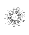
- FIG. 2 is a horizontal sectional view showing the permanent magnet motor 10.
- This permanent magnet motor 10 is of a three-phase six-pole nine-slot type, and has a rotor 13 and a concentrated winding stator 14 disposed on the outer periphery of the rotor 13.
- the rotor 13 has a rotor core 15 formed in a cylindrical shape by laminating thin steel plates, and the rotor core 15 is fixed to the rotating shaft 12.
- the rotor core 15 six plate-like permanent magnets 16 are installed at equal intervals along the circumferential direction of the rotor core 15.
- the concentrated winding stator 14 has a stator core 17 formed in a cylindrical shape by laminating thin steel plates, and the stator core 17 has nine slots along the circumferential direction of the stator core 17. 18 are formed at equal intervals, and magnetic pole teeth 19 projecting in the inner peripheral direction are formed at portions between adjacent slots 18. A winding 20 is wound around each magnetic pole tooth 19. The winding 20 is continuously wound with three windings 20 alternately changing the winding direction for every three phases (U phase, V phase, W phase).
- the three windings 20U1, 20U2, and 20U3 are continuously wound, and the winding direction of the winding 20U2 is opposite (left-handed) to the winding direction of the winding 20U1 (for example, right-handed). Furthermore, the winding direction of the winding 20U3 is reversed (right-handed) with respect to the winding direction (left-handed) of the winding 20U2.
- winding direction of the winding 20V2 is reversed (left-handed) with respect to the winding direction of the winding 20V1 (for example, right-handed).
- winding direction of the winding 20V3 is reversed (right-handed) with respect to the winding direction (left-handed) of the winding 20V2.
- winding direction of the winding 20W2 is reversed (left-handed) with respect to the winding direction of the winding 20W1 (eg, right-handed).
- winding direction of the winding 20W3 is reversed (right-handed) with respect to the winding direction (left-handed) of the winding 20W2.
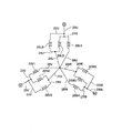
- FIG. 3 is a connection diagram showing a connection state of the three-phase winding 20.
- the connecting wire 21U between the two U-phase windings 20U1 and 20U2 and the terminal wire 22U of the winding 20U3 are connected to form an end on the lead wire 23U side.
- the connecting wire 21V between the two V-phase windings 20V1 and 20V2 and the terminal wire 22V of the winding 20V3 are connected to form an end on the lead wire 23V side.
- the connecting wire 21W between the two windings W1, W2 of the W phase and the terminal wire 22W of the winding 20W3 are connected to form an end on the lead wire 23W side.
- the lead wire 25W connected to 24W and the terminal wire 26W of the W-phase winding 20W1 are connected.
- FIG. 4 shows a pressure contact terminal 27 used when connecting the connecting wire 21 and the terminal wire 22 (the connecting wire 21U and the terminal wire 22U, 21V and 22V, 21W and 22W).
- the pressure contact terminal 27 includes three pressure contact protrusions 28, two pressure contact slots 29 that are located between adjacent pressure contact protrusions 28 and cut into a U shape, and lead wires 23 ( 23U, 23V, and 23W) are formed.
- FIG. 5 is a plan view showing a wiring state of the connecting wire 21 and the terminal wire 22 connected using the press contact terminal 27.
- a winding receiver 32 is fixed to the end face side of the stator core 17, and a holding portion 33 for holding the jumper wire 21 and the terminal wire 22 and a pressing contact projection 28 of the press contact terminal 27 are provided on the winding receiver 32.
- An insertion portion 34 to be inserted is formed.
- FIG. 6 shows a connection state between the connecting wire 21 and the terminal wire 22 by the press contact terminal 27.
- the pressure contact protrusion 28 of the pressure contact terminal 27 is inserted into the insertion portion 34 of the winding receiver 32, and the crossover wire 21 and the terminal wire 22 held by the holding portion 33 are press-fitted into the pressure contact slot 29. Furthermore, a lead wire 23 is connected to the tab 30.
- a blade portion is formed on the peripheral edge of the pressure contact slot 29, and the coating of the crossover wire 21 and the terminal wire 22 is broken by the blade portion when the crossover wire 21 and the terminal wire 22 are press-fitted into the pressure contact slot 29.
- the crossover wire 21 and the terminal wire 22 are electrically connected via the press contact terminal 27.
- the hermetic compressor 4 when the permanent magnet motor 10 is energized, the rotary shaft 12 rotates around the center line, and the rotation of the rotary shaft 12 drives the compression mechanism unit 11, The gas refrigerant is compressed in the compression mechanism 11.
- the compressed gas refrigerant is discharged from the compression mechanism 11 into the sealed case 9, and the high-pressure gas refrigerant discharged into the sealed case 9 passes again through the condenser 5, the expansion device 6, and the evaporator 7 in order.
- a refrigeration cycle is performed by circulating to the compression mechanism 11.
- the connecting wire 21 (21U) and one of the two windings 20 for example, 20U1 and 20U2. Since the terminal wire 22 (22U) of the winding 20 (20U3) is connected to the lead wire 23 (23U), the number of wires connected to the lead wire 23 is reduced, and the connection work is facilitated. .
- connection between the crossover wire 21 and the terminal wire 22 is performed using the pressure contact terminal 27 having two pressure contact slots 29, it is not necessary to peel off the film of the crossover wire 21 and the terminal wire 22, and the connection is made. Work can be done without much effort.
- the basic configuration of the second embodiment is the same as that of the first embodiment.
- the second embodiment is different from the first embodiment in order to connect the crossover line 21 and the terminal line 22.
- the fusing terminal 41 is used instead of the press contact terminal 27.
- the fusing terminal 41 is formed with a fusing portion 42 that sandwiches the connecting wire 21 and the terminal wire 22 to be connected, and a tab 30 for connecting the lead wire 23. ing.
- the connecting wire 21 and the terminal wire 22 are arranged in parallel and sandwiched by the fusing portion 42, and the fusing portion 42 is pressurized. This is done by passing an electric current and welding the connecting wire 21, the terminal wire 22, and the fusing terminal 41.
- the fusing terminal 41 may be provided in the routing path of the crossover wire 21 and can be attached to, for example, the outer flange of the insulator provided in the concentrated winding stator 14.
- connection using the fusing terminal 41 it is possible to connect without peeling off the film of the crossover wire 21 and the terminal wire 22, and the labor for removing the film is reduced.
- a third embodiment will be described with reference to FIG.
- the basic configuration of the third embodiment is the same as that of the first embodiment, and the difference between the third embodiment and the first embodiment is the connection structure between the jumper wire 21 and the terminal line 22. is there.
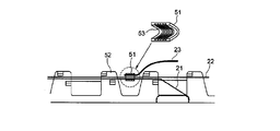
- the connecting wire 21, the terminal wire 22, and the core wire of the lead wire 23 are arranged in parallel, and the connecting wire 21, the terminal wire 22, and the core wire of the lead wire 23 are connected to the crimp terminal 51.
- the connecting wire 21 and the terminal wire 22 are placed on the outer flange portion of the insulator 52 provided in the concentrated winding stator 14.
- the crimp terminal 51 is formed in a substantially V shape with one end side expanded, and a groove 53 is formed inside thereof.
- the connecting wire 21, the terminal wire 22 and the core wire of the lead wire 23 are electrically connected.
- the connecting wire 21 of the two windings 20 and the terminal wire 22 of the one winding 20 are connected.
- the core wire of the lead wire 23 may be crimped by the crimp terminal 51, and the number of wires to be crimped is reduced, so that a highly reliable connection state can be obtained.
- the crossover 21, the terminal wire 22 and the core wire of the lead wire 23 can be connected at the same time, and the lead wire 23 is connected to the crossover wire 21 and the terminal wire 22 previously connected. It is no longer necessary to connect the devices later, and the number of steps of connection work can be reduced.
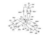
- the first neutral point 61 is formed by connecting at least two crossover lines 24U, 24V, and 24W on the neutral point side, and the remaining terminal lines 26U, 26V, and 26W are connected. Is connected to the second neutral point 62.
- connection of the connecting wires 24U, 24V, 24W is performed using a crimp terminal 51 as shown in FIG.
- FIG. 11 shows a connection pressure contact terminal 63 for connecting the terminal lines 26U, 26V, and 26W.
- the connecting press contact terminal 63 is formed by connecting two press contact terminals 64 with a connecting portion 65.
- Each press contact terminal 64 is formed with two press contact slots 29 and three press contact projections 28, similarly to the press contact terminal 27 shown in FIG. 4.
- FIG. 12 is a plan view showing a wiring state of the three terminal lines 26U, 26V, and 26W connected by using the connecting pressure contact terminal 63.
- FIG. A winding receiver 66 is fixed to the end face side of the stator core 17, and a holding portion 67 for holding the three terminal wires 26U, 26V, and 26W and a pressing contact projection 28 are inserted into the winding receiver 66.
- the insertion portion 68 is formed.
- the connection press-contact terminal having four press-contact slots 29 is provided. Even if the three terminal lines 26U, 26V, and 26W are connected using 63, a balanced connection state can be obtained. Moreover, when the terminal line 26W is press-fitted across the pressure contact slots 29 of the two pressure contact terminals 64, the terminal line 26W functions as a connection line for the two pressure contact terminals 64, and The cross-sectional area of the conductor can be supplemented.
Landscapes
- Engineering & Computer Science (AREA)
- Power Engineering (AREA)
- Windings For Motors And Generators (AREA)
- Insulation, Fastening Of Motor, Generator Windings (AREA)
Abstract
6極9スロットの集中巻固定子を有する永久磁石電動機において、巻線の接続構造を簡単化した永久磁石電動機、密閉型圧縮機及び冷凍サイクル装置を提供する。 【解決手段】各相3個の巻線20を有する9スロットの集中巻固定子14を有する永久磁石電動機において、各相の3個の巻線20が交互に巻方向を変えて連続して巻装され、各相ごとに2個の巻線20間の渡り線21と他の巻線20の端末線22とが接続されて口出線23側端部とされている。
Description
本発明の実施形態は、永久磁石電動機、この永久磁石電動機を用いた密閉型圧縮機及びこの密閉型圧縮機を用いた冷凍サイクル装置に関する。
従来、固定子鉄心の磁極歯に巻線を巻装した永久磁石電動機としては、種々の構造のものが知られている(下記特許文献1、2参照)。
このような永久磁石電動機において各相の巻線を並列接続する場合に、その永久磁石電動機が3相6極9スロットタイプであると、各相(U相、V相、W相)ごとに6本、合計で18本の端末線が発生する。
そして、各相の口出線に対するそれぞれ3本の端末線の接続は、ハンダ付けや溶着により行われている。
また、中性点側の端末線の接続においては、1箇所に接続する場合は9本の端末線を接続する必要がある。
しかしながら、各相の口出線に端末線を3本ずつ接続する場合には、接続する端末線の本数が多くなるため、手間がかかっている。
そして、これらの接続をハンダ付けや溶着で行う場合には、端末線の被覆を剥離する必要があり、剥離した被膜片が永久磁石電動機の回転部の隙間に入り込み、永久磁石電動機の性能を損なう場合がある。さらに、ハンダ付けや溶着した接続部に絶縁体を被せ、どこかに固定するという対策をとる必要がある。また、ハンダ付けや溶着による接続作業は、作業のバラツキにより永久磁石電動機の性能を損なう場合がある。
また、中性点の接続においても、1箇所に接続する場合は9本の端末線を接続する必要があり、被膜を剥離しての溶着あるいはハンダ付けとなり、端末線の引き回し処理と合わせて多大な工数を要する。
本発明の目的は、9スロットの集中巻固定子を有する永久磁石電動機において、巻線の接続構造を簡単化することができる永久磁石電動機、密閉型圧縮機及び冷凍サイクル装置を提供するものである。
実施形態の永久磁石電動機は、各相3個の巻線を有する9スロットの集中巻固定子を有する永久磁石電動機において、各相の3個の巻線が交互に巻方向を変えて連続して巻装され、各相ごとに2個の巻線間の渡り線と他の巻線の端末線とが接続されて口出線側端部とされていることを特徴とする。
また、密閉型圧縮機は、上記永久磁石電動機と、前記永久磁石電動機の回転軸に連結されて駆動されることにより作動流体を圧縮する圧縮機構部と、前記永久磁石電動機と前記圧縮機構部とを収容する密閉ケースと、を備えることを特徴とする。
更に、冷凍サイクル装置は、前記密閉型圧縮機と、前記密閉型圧縮機に接続される凝縮器と、前記凝縮器に接続される膨張装置と、前記膨張装置と前記密閉型圧縮機との間に接続される蒸発器とを備えることを特徴とする。
本発明によれば、9スロットの集中巻固定子を有する永久磁石電動機において、巻線の接続構造を簡単化することができる永久磁石電動機、密閉型圧縮機及び冷凍サイクル装置を提供できる。
(第1の実施形態)
第1の実施形態について、図1ないし図6に基づいて説明する。図1は冷凍サイクル装置1を示しており、この冷凍サイクル装置1は、圧縮機本体2とアキュムレータ3とを有して作動流体であるガス冷媒を圧縮する密閉型圧縮機4と、圧縮機本体2に接続されて圧縮機本体2から吐出された高圧のガス冷媒を凝縮して液冷媒にする凝縮器5と、凝縮器5に接続されて液冷媒を減圧する膨張装置6と、膨張装置6とアキュムレータ3との間に接続されて液冷媒を蒸発させる蒸発器7と、を有している。アキュムレータ3と圧縮機本体2とは、ガス冷媒が流れる吸込管8により接続されている。
第1の実施形態について、図1ないし図6に基づいて説明する。図1は冷凍サイクル装置1を示しており、この冷凍サイクル装置1は、圧縮機本体2とアキュムレータ3とを有して作動流体であるガス冷媒を圧縮する密閉型圧縮機4と、圧縮機本体2に接続されて圧縮機本体2から吐出された高圧のガス冷媒を凝縮して液冷媒にする凝縮器5と、凝縮器5に接続されて液冷媒を減圧する膨張装置6と、膨張装置6とアキュムレータ3との間に接続されて液冷媒を蒸発させる蒸発器7と、を有している。アキュムレータ3と圧縮機本体2とは、ガス冷媒が流れる吸込管8により接続されている。
圧縮機本体2は、円筒状に形成された密閉ケース9を有し、密閉ケース9内には、上部側に位置する永久磁石電動機10と、下部側に位置する圧縮機構部11とが収容されている。永久磁石電動機10には上下方向に沿う中心線を有する回転軸12が設けられており、この回転軸12に圧縮機構部11が連結されている。
永久磁石電動機10は、圧縮機構部11を駆動する部分であり、回転軸12に固定された回転子13と、密閉ケース9の内面に固定されて回転子13を囲む位置に配置された集中巻固定子14とを有している。
圧縮機構部11は、ガス冷媒を圧縮する部分であり、吸込管8を介して吸込まれるガス冷媒を圧縮する圧縮要素(図示せず)を有している。この圧縮要素は、ガス冷媒が流入するシリンダ室を有するシリンダ、回転軸12の偏心部に嵌合されてシリンダ室内を偏心回転するローラ、先端部をローラの外周面に当接させて摺動可能に設けられることによりシリンダ室内をガス冷媒の吸込室と圧縮室とに区画するブレード等により構成されている。圧縮機構部11において圧縮されて高圧になったガス冷媒は、密閉ケース9内に吐出される。
図2は、永久磁石電動機10を示す水平断面図である。この永久磁石電動機10は、3相6極9スロットタイプのものであり、回転子13と回転子13の外周部に配置された集中巻固定子14とを有している。
回転子13は、薄板状の鉄板を積層して円筒状に形成された回転子鉄心15を有し、この回転子鉄心15が回転軸12に固定されている。回転子鉄心15の内部には、6個の板状の永久磁石16が回転子鉄心15の周方向に沿って等間隔に設置されている。
集中巻固定子14は、薄板状の鉄板を積層して円筒状に形成された固定子鉄心17を有し、固定子鉄心17には、固定子鉄心17の周方向にそって9個のスロット18が等間隔で形成されており、隣合って位置するスロット18の間の部分に内周方向に向けて突出する磁極歯19が形成される。各磁極歯19には、それぞれ巻線20が巻装されている。巻線20は、3個の相(U相、V相、W相)ごとに3個の巻線20が交互に巻方向を変えて連続して巻装されている。
すなわち、U相は、20U1、20U2、20U3の3個の巻線20が連続して巻装され、巻線20U1の巻方向(例えば右巻き)に対し、巻線20U2の巻方向は逆(左巻き)にされ、さらに、巻線20U2の巻方向(左巻き)に対して、巻線20U3の巻方向は逆(右巻き)にされている。
V相は、20V1、20V2、20V3の3個の巻線20が連続して巻装され、巻線20V1の巻方向(例えば右巻き)に対し、巻線20V2の巻方向は逆(左巻き)にされ、さらに、巻線20V2の巻方向(左巻き)に対して、巻線20V3の巻方向は逆(右巻き)にされている。
W相は、20W1、20W2、20W3の3個の巻線20が連続して巻装され、巻線20W1の巻方向(例えば右巻き)に対し、巻線20W2の巻方向は逆(左巻き)にされ、さらに、巻線20W2の巻方向(左巻き)に対して、巻線20W3の巻方向は逆(右巻き)にされている。
ここで、巻線20、後述する渡り線、端末線、リード線、口出線については、各相との関係を説明する場合には各相を意味するU、V、Wの符号を付けて説明するが、各相との関連を説明する必要がない場合には、必要に応じてU、V、Wの符号は省略する。
図3は、3相の巻線20の接続状態を示す結線図である。電源側においては、U相の2個の巻線20U1、20U2の間の渡り線21Uと巻線20U3の端末線22Uとが接続されて口出線23U側の端部とされている。
同様に、V相においても、V相の2個の巻線20V1、20V2の間の渡り線21Vと巻線20V3の端末線22Vとが接続されて口出線23V側の端部とされている。同様に、W相においても、W相の2個の巻線W1、W2の間の渡り線21Wと巻線20W3の端末線22Wとが接続されて口出線23W側の端部とされている。
中性点側においては、U相の2個の巻線20U2、20U3の間の渡り線24Uに接続されたリード線25Uと、U相の巻線20U1の端末線26Uと、V相の2個の巻線20V2、20V3の間の渡り線24Vに接続されたリード線25Vと、V相の巻線20V1の端末線26Vと、W相の2個の巻線20W2、20W3との間の渡り線24Wに接続されたリード線25Wと、W相の巻線20W1の端末線26Wとが、接続されている。
図4は、渡り線21と端末線22とを接続する場合(渡り線21Uと端末線22U、21Vと22V、21Wと22W)に使用する圧接端子27である。圧接端子27には、3個の圧接用突部28と、隣り合う圧接用突部28の間に位置してU字状に切り込まれた2個の圧接スロット29と、口出線23(23U、23V、23W)を接続するためのタブ30とが形成されている。
図5は、圧接端子27を用いて接続される渡り線21と端末線22との配線状態を示す平面図である。固定子鉄心17の端面側には巻線受け32が固定され、この巻線受け32には渡り線21と端末線22とを保持する保持部33と、圧接端子27の圧接用突部28が挿入される挿入部34とが形成されている。
図6は、圧接端子27による渡り線21と端末線22との接続状態を示している。圧接端子27の圧接用突部28が巻線受け32の挿入部34に挿入されるとともに、保持部33に保持された渡り線21と端末線22とが圧接スロット29に圧入されている。さらに、タブ30に口出線23が接続されている。
圧接スロット29の周縁には刃部が形成されており、渡り線21と端末線22とが圧接スロット29に圧入されることにより渡り線21と端末線22との被膜が刃部により破られ、渡り線21と端末線22とが圧接端子27を介して電気的に接続される。
このような構成において、この密閉型圧縮機4においては、永久磁石電動機10に通電されることにより回転軸12が中心線回りに回転し、回転軸12の回転により圧縮機構部11が駆動され、圧縮機構部11においてガス冷媒が圧縮される。
圧縮されたガス冷媒は圧縮機構部11から密閉ケース9内に吐出され、密閉ケース9内に吐出された高圧のガス冷媒は、凝縮器5、膨張装置6、蒸発器7を順に経由して再び圧縮機構部11へ循環することにより、冷凍サイクルが実行される。
ここで、3相の永久磁石電動機10の巻線20を通電側の口出線23に接続する場合において、2個の巻線20(例えば20U1と20U2)の渡り線21(21U)と1個の巻線20(20U3)の端末線22(22U)とを口出線23(23U)に接続しているため、口出線23に接続する配線の本数が少なくなり、接続作業が容易になる。
しかも、渡り線21と端末線22との接続を、2個の圧接スロット29を有する圧接端子27を用いて行っているため、渡り線21と端末線22の皮膜を剥離する必要がなく、接続作業を手間をかけず行うことができる。
しかも、被膜を剥離することによる被膜片の発生がなく、発生した被膜片が永久磁石電動機10の回転部の隙間に入り込み、永久磁石電動機10の性能を損なうということが発生しない。
(第2の実施形態)
第2の実施形態について、図7及び図8に基づいて説明する。なお、第2の実施形態以降の各実施形態において、第1の実施形態において説明した構成要素と同じ構成要素には同じ符号を付け、重複する説明は省略する。
第2の実施形態について、図7及び図8に基づいて説明する。なお、第2の実施形態以降の各実施形態において、第1の実施形態において説明した構成要素と同じ構成要素には同じ符号を付け、重複する説明は省略する。
第2の実施形態の基本的な構成は第1の実施形態と同じであり、第2の実施形態が第1の実施形態と異なる点は、渡り線21と端末線22とを接続するために、圧接端子27に代えてヒュージング端子41を用いた点である。
図7及び図8に示すように、ヒュージング端子41には、接続する渡り線21と端末線22とを挟み込むヒュージング部42と、口出線23を接続するためのタブ30とが形成されている。
ヒュージング端子41を用いた渡り線21と端末線22との接続は、渡り線21と端末線22とを平行に重ねて配列してヒュージング部42で挟み込み、ヒュージング部42を加圧するとともに電流を流し、渡り線21と端末線22とヒュージング端子41とを溶着することにより行われている。
ヒュージング端子41は渡り線21の引き回し経路に設ければよく、例えば、集中巻固定子14に設けられている絶縁体の外側鍔部に取付けることができる。
このような構成のヒュージング端子41を用いて配線を接続する場合において、接続する配線の本数が3本以上になると、加圧や電流のバラツキにより接続不良が発生しやすくなる。しかし本実施形態では、3相の永久磁石電動機10の巻線20を通電側の口出線23に接続する場合において、2個の巻線20の渡り線21と1個の巻線20の端末線22とをヒュージング端子41を用いて接続しているため、ヒュージング端子41を用いて接続する配線の本数が2本となり、溶着不良を生じることなく信頼性の高い接続状態を得ることができる。
また、ヒュージング端子41を用いた接続では、渡り線21や端末線22の皮膜を剥がすことなく接続することができ、被膜を剥がす手間が軽減される。
(第3の実施形態)
第3の実施形態について、図9に基づいて説明する。第3の実施形態の基本的な構成は第1の実施形態と同じであり、第3の実施形態と第1の実施形態との異なる点は、渡り線21と端末線22との接続構造である。
第3の実施形態について、図9に基づいて説明する。第3の実施形態の基本的な構成は第1の実施形態と同じであり、第3の実施形態と第1の実施形態との異なる点は、渡り線21と端末線22との接続構造である。
第3の実施形態では、渡り線21と端末線22と口出線23の芯線とが平行に並べて配置され、これらの渡り線21と端末線22と口出線23の芯線とが圧着端子51により圧着接続されている。渡り線21と端末線22とは、例えば、集中巻固定子14に設けられている絶縁体52の外側鍔部に這わせておく。
圧着端子51は、図9に示すように一端側が拡開された略V字形に形成されており、その内側には溝53が形成されている。圧着端子51の内側に渡り線21と端末線22と、口出線23の芯線とを位置させて拡開側をかしめることにより、溝53により渡り線21と端末線22との被膜が破られ、渡り線21と端末線22と口出線23の芯線とが電気的に接続される。
このような構成の3相永久磁石電動機10の巻線20を通電側の口出線23に接続する場合において、2個の巻線20の渡り線21と1個の巻線20の端末線22と、口出線23の芯線とを圧着端子51で圧着すればよく、圧着する配線の数が少なくなるため信頼性の高い接続状態を得ることができる。
また、圧着端子51による接続では、渡り21と端末線22と口出線23の芯線とを同時に接続することができ、先に接続した渡り線21と端末線22とに対して口出線23を後から接続するという必要がなくなり、接続作業の工程数を少なくすることができる。
(第4の実施形態)
本発明の第4の実施形態を図10乃至図12に基づいて説明する。第4の実施形態の基本的な構成は第1の実施形態と同じであり、第4の実施形態と第1の実施形態との異なる点は、中性点側の結線構造である。
本発明の第4の実施形態を図10乃至図12に基づいて説明する。第4の実施形態の基本的な構成は第1の実施形態と同じであり、第4の実施形態と第1の実施形態との異なる点は、中性点側の結線構造である。
図10に示すように、中性点側の3本の渡り線24U、24V、24Wを少なくとも2箇所で接続することにより第1の中性点61とされ、残りの端末線26U、26V、26Wを接続することにより第2の中性点62とされている。
渡り線24U、24V、24Wの接続は、図9に示したような圧着端子51を用いて行われている。
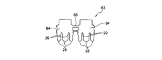
図11は、端末線26U、26V、26Wを接続する連結圧接端子63を示している。この連結圧接端子63は、2個の圧接端子64を連結部65で連結ことにより形成されている。各圧接端子64には、図4に示した圧接端子27と同様に、2個の圧接スロット29と3個の圧接用突部28とが形成されている。
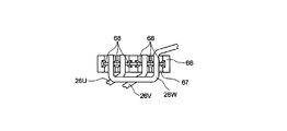
図12は、連結圧接端子63を用いて接続される3本の端末線26U、26V、26Wの配線状態を示す平面図である。固定子鉄心17の端面側には巻線受け66が固定され、この巻線受け66には3本の端末線26U、26V、26Wを保持する保持部67と、圧接用突部28が挿入される挿入部68とが形成されている。1本の端末線26Wは、2箇所で保持されるように引き回して配線され、圧接用突部28が巻線受け66の挿入部68に挿入された場合、端末線26Wは2個の圧接スロット29に圧入される。
このような構成において、第1の中性点61(図10参照)においては、2本の渡り線24を圧着端子51を用いて接続する構成であるので、圧着する配線の数が少なくなり信頼性の高い接続状態を得ることができる。
第2の中性点62においては、1本の端末線26Wを各圧接端子64の圧接スロット29に圧入されるように引き回して配線されているため、4個の圧接スロット29を有する連結圧接端子63を用いて3本の端末線26U、26V、26Wを接続しても、バランスのよい接続状態とすることができる。しかも、端末線26Wが2個の圧接端子64の圧接スロット29に跨って圧入されることにより、この端末線26Wが2個の圧接端子64の連結線として機能することになり、連結部65の導体断面積を補うことができる。
以上、本発明のいくつかの実施形態を説明したが、これらの実施形態は、例として提示したものであり、発明の範囲を限定することは意図していない。これらの実施形態は、その他の様々な形態で実施されることが可能であり、発明の要旨を逸脱しない範囲で、種々の省略、置き換え、変更を行うことができる。これらの実施形態やその変形は、発明の範囲や要旨に含まれると同様に、特許請求の範囲に記載された発明とその均等の範囲に含まれるものである。
1…冷凍サイクル装置、4…密閉型圧縮機、5…凝縮器、6…膨張装置、7…蒸発器、9…密閉ケース、10…永久磁石電動機、11…圧縮機構部、14…集中巻固定子、20…巻線、21…渡り線、22…端末線、23…口出線、24…渡り線、26…端末線、27…圧接端子、29…圧接スロット、51…圧着端子、61…第1の中性点、62…第2の中性点、63…連結圧接端子、64…圧接端子
Claims (7)
- 各相3個の巻線を有する9スロットの集中巻固定子を有する永久磁石電動機において、
各相の3個の前記巻線が交互に巻方向を変えて連続して巻装され、
各相ごとに2個の前記巻線間の渡り線と他の前記巻線の端末線とが接続されて口出線側端部とされていることを特徴とする永久磁石電動機。 - 前記渡り線と前記端末線とは、これらの渡り線と端末線とが圧入される2個の圧接スロットを有する圧接端子により接続されていることを特徴とする請求項1記載の永久磁石電動機。
- 前記渡り線と前記端末線と口出線の芯線とが並べて配置され、これらの各線が圧着端子により接続されていることを特徴とする請求項1記載の永久磁石電動機。
- 各相3個の巻線を有する9スロットの集中巻固定子を有する永久磁石電動機において、
各相の3個の前記巻線が交互に巻方向を変えて連続して巻装され、
各相の2個の前記巻線間の渡り線と他の前記巻線の端末線とが接続されて口出線側端部とされ、
各相の残りの渡り線同士が少なくとも2箇所で接続されて第1の中性点とされ、
各相の残りの端末線の3本が接続されて第2の中性点とされていることを特徴とする永久磁石電動機。 - 各相の残りの前記端末線の3本は、2個の圧接スロットを有する圧接端子を2つ連結した構造の連結圧接端子により接続され、1本の前記端末線は2個の前記圧接端子の前記圧接スロットにまたがって引き回されていることを特徴とする請求項4記載の永久磁石電動機。
- 請求項1ないし5のいずれか一項に記載の永久磁石電動機と、
前記永久磁石電動機の回転軸に連結されて駆動されることにより作動流体を圧縮する圧縮機構部と、
前記永久磁石電動機と前記圧縮機構部とを収容する密閉ケースと、
を備えることを特徴とする密閉型圧縮機。 - 請求項6記載の密閉型圧縮機と、前記密閉型圧縮機に接続される凝縮器と、前記凝縮器に接続される膨張装置と、前記膨張装置と前記密閉型圧縮機との間に接続される蒸発器とを備えることを特徴とする冷凍サイクル装置。
Applications Claiming Priority (2)
| Application Number | Priority Date | Filing Date | Title |
|---|---|---|---|
| JP2013200860A JP2015070652A (ja) | 2013-09-27 | 2013-09-27 | 永久磁石電動機、密閉型圧縮機及び冷凍サイクル装置 |
| JP2013-200860 | 2013-09-27 |
Publications (1)
| Publication Number | Publication Date |
|---|---|
| WO2015045331A1 true WO2015045331A1 (ja) | 2015-04-02 |
Family
ID=52742504
Family Applications (1)
| Application Number | Title | Priority Date | Filing Date |
|---|---|---|---|
| PCT/JP2014/004777 Ceased WO2015045331A1 (ja) | 2013-09-27 | 2014-09-17 | 永久磁石電動機、密閉型圧縮機及び冷凍サイクル装置 |
Country Status (2)
| Country | Link |
|---|---|
| JP (1) | JP2015070652A (ja) |
| WO (1) | WO2015045331A1 (ja) |
Cited By (3)
| Publication number | Priority date | Publication date | Assignee | Title |
|---|---|---|---|---|
| JP6727457B1 (ja) * | 2019-03-27 | 2020-07-22 | 三菱電機株式会社 | ステータおよび電動機 |
| WO2021019751A1 (ja) * | 2019-07-31 | 2021-02-04 | 東芝キヤリア株式会社 | 電動機、圧縮機、冷凍サイクル装置および電動機の製造方法 |
| EP3975388A4 (en) * | 2019-05-20 | 2022-07-13 | Gree Electric Appliances, Inc. of Zhuhai | MAGNETIC LEVEL BEARING, STATOR, WINDING AND METHOD OF MANUFACTURE THEREOF, MOTOR AND COMPRESSOR |
Families Citing this family (5)
| Publication number | Priority date | Publication date | Assignee | Title |
|---|---|---|---|---|
| JP6739529B2 (ja) * | 2016-07-08 | 2020-08-12 | 三菱電機株式会社 | 回転電機の固定子、回転電機及び圧縮機 |
| CZ309981B6 (cs) | 2017-08-03 | 2024-04-03 | Mitsubishi Electric Corporation | Stator, elektrický motor a hermetický kompresor |
| JP7270158B2 (ja) * | 2018-02-22 | 2023-05-10 | パナソニックIpマネジメント株式会社 | 圧縮機用モータ、圧縮機、および、圧縮機用モータの製造方法 |
| DE102019116257A1 (de) * | 2019-06-14 | 2020-12-17 | Nidec Gpm Gmbh | Anschlusselement für eine Wicklung eines Stators an einer Leiterplatte mit wenigstens zwei Schneidklemm-Kontakten |
| JP2024162360A (ja) * | 2023-05-10 | 2024-11-21 | 株式会社デンソー | 回転電機 |
Citations (5)
| Publication number | Priority date | Publication date | Assignee | Title |
|---|---|---|---|---|
| JP2001275292A (ja) * | 2000-03-27 | 2001-10-05 | Mitsubishi Electric Corp | 3相電動機 |
| JP2002153003A (ja) * | 2000-11-13 | 2002-05-24 | Nippon Densan Corp | モータ用ステータ |
| JP2003189525A (ja) * | 2001-12-20 | 2003-07-04 | Hitachi Ltd | 回転電機 |
| JP2003230257A (ja) * | 2001-11-30 | 2003-08-15 | Sanko Kiki Co Ltd | ステータコアへの巻線方法 |
| JP2005130586A (ja) * | 2003-10-23 | 2005-05-19 | Mitsubishi Electric Corp | 電動機の固定子 |
-
2013
- 2013-09-27 JP JP2013200860A patent/JP2015070652A/ja active Pending
-
2014
- 2014-09-17 WO PCT/JP2014/004777 patent/WO2015045331A1/ja not_active Ceased
Patent Citations (5)
| Publication number | Priority date | Publication date | Assignee | Title |
|---|---|---|---|---|
| JP2001275292A (ja) * | 2000-03-27 | 2001-10-05 | Mitsubishi Electric Corp | 3相電動機 |
| JP2002153003A (ja) * | 2000-11-13 | 2002-05-24 | Nippon Densan Corp | モータ用ステータ |
| JP2003230257A (ja) * | 2001-11-30 | 2003-08-15 | Sanko Kiki Co Ltd | ステータコアへの巻線方法 |
| JP2003189525A (ja) * | 2001-12-20 | 2003-07-04 | Hitachi Ltd | 回転電機 |
| JP2005130586A (ja) * | 2003-10-23 | 2005-05-19 | Mitsubishi Electric Corp | 電動機の固定子 |
Cited By (8)
| Publication number | Priority date | Publication date | Assignee | Title |
|---|---|---|---|---|
| JP6727457B1 (ja) * | 2019-03-27 | 2020-07-22 | 三菱電機株式会社 | ステータおよび電動機 |
| CN113615047A (zh) * | 2019-03-27 | 2021-11-05 | 三菱电机株式会社 | 定子及电动机 |
| CN113615047B (zh) * | 2019-03-27 | 2022-05-06 | 三菱电机株式会社 | 定子及电动机 |
| EP3975388A4 (en) * | 2019-05-20 | 2022-07-13 | Gree Electric Appliances, Inc. of Zhuhai | MAGNETIC LEVEL BEARING, STATOR, WINDING AND METHOD OF MANUFACTURE THEREOF, MOTOR AND COMPRESSOR |
| WO2021019751A1 (ja) * | 2019-07-31 | 2021-02-04 | 東芝キヤリア株式会社 | 電動機、圧縮機、冷凍サイクル装置および電動機の製造方法 |
| JPWO2021019751A1 (ja) * | 2019-07-31 | 2021-02-04 | ||
| JP7225407B2 (ja) | 2019-07-31 | 2023-02-20 | 東芝キヤリア株式会社 | 電動機、圧縮機、冷凍サイクル装置および電動機の製造方法 |
| EP4007127A4 (en) * | 2019-07-31 | 2023-04-19 | Toshiba Carrier Corporation | ELECTRIC MOTOR, COMPRESSOR, REFRIGERATION CYCLE DEVICE AND MANUFACTURING METHOD FOR AN ELECTRIC MOTOR |
Also Published As
| Publication number | Publication date |
|---|---|
| JP2015070652A (ja) | 2015-04-13 |
Similar Documents
| Publication | Publication Date | Title |
|---|---|---|
| JP2015070652A (ja) | 永久磁石電動機、密閉型圧縮機及び冷凍サイクル装置 | |
| JP5772296B2 (ja) | 電動圧縮機 | |
| JP5637112B2 (ja) | 電動圧縮機 | |
| JP7225407B2 (ja) | 電動機、圧縮機、冷凍サイクル装置および電動機の製造方法 | |
| JP6739529B2 (ja) | 回転電機の固定子、回転電機及び圧縮機 | |
| JP2009112094A (ja) | 回転電機における相間絶縁シート及び電動圧縮機 | |
| JP2020048303A (ja) | モータ及び圧縮機 | |
| US8841806B2 (en) | Electric motor and motor-driven compressor using the same | |
| JP2009077583A (ja) | 回転電機における相間絶縁シート、相間絶縁シートの製造方法及び電動圧縮機 | |
| JP5713975B2 (ja) | 電動機の固定子、電動機、密閉型圧縮機および回転機械 | |
| JP4178558B2 (ja) | 回転電機 | |
| CN204243953U (zh) | 电动机的定子、送风机用电动机以及空调机 | |
| JP5950873B2 (ja) | 三相電動機、密閉型圧縮機、及び、冷凍サイクル装置 | |
| JP5679833B2 (ja) | 回転電機の固定子、回転電機及び圧縮機 | |
| CN203774922U (zh) | 压缩机用电动机、压缩机以及制冷循环装置 | |
| CN102777344B (zh) | 密闭型电动压缩机 | |
| CN115133692A (zh) | 马达、压缩机以及制冷循环装置 | |
| JP2015116086A (ja) | 回転電機、および車載用電動圧縮機 | |
| CN111247719A (zh) | 定子、电动机和压缩机 | |
| JP6368143B2 (ja) | 密閉型圧縮機及び冷凍サイクル装置 | |
| JP6005296B2 (ja) | 電動機またはそれを用いた圧縮機 | |
| JP2011130635A (ja) | 端末モジュール | |
| JP2009077584A (ja) | 回転電機における相間絶縁シート及び電動圧縮機 |
Legal Events
| Date | Code | Title | Description |
|---|---|---|---|
| 121 | Ep: the epo has been informed by wipo that ep was designated in this application |
Ref document number: 14847712 Country of ref document: EP Kind code of ref document: A1 |
|
| NENP | Non-entry into the national phase |
Ref country code: DE |
|
| 122 | Ep: pct application non-entry in european phase |
Ref document number: 14847712 Country of ref document: EP Kind code of ref document: A1 |