WO2015030165A1 - ガス濃度検出装置 - Google Patents
ガス濃度検出装置 Download PDFInfo
- Publication number
- WO2015030165A1 WO2015030165A1 PCT/JP2014/072719 JP2014072719W WO2015030165A1 WO 2015030165 A1 WO2015030165 A1 WO 2015030165A1 JP 2014072719 W JP2014072719 W JP 2014072719W WO 2015030165 A1 WO2015030165 A1 WO 2015030165A1
- Authority
- WO
- WIPO (PCT)
- Prior art keywords
- gas
- current
- concentration
- cell current
- sensor
- Prior art date
- Legal status (The legal status is an assumption and is not a legal conclusion. Google has not performed a legal analysis and makes no representation as to the accuracy of the status listed.)
- Ceased
Links
Images






Classifications
-
- G—PHYSICS
- G01—MEASURING; TESTING
- G01N—INVESTIGATING OR ANALYSING MATERIALS BY DETERMINING THEIR CHEMICAL OR PHYSICAL PROPERTIES
- G01N27/00—Investigating or analysing materials by the use of electric, electrochemical, or magnetic means
- G01N27/26—Investigating or analysing materials by the use of electric, electrochemical, or magnetic means by investigating electrochemical variables; by using electrolysis or electrophoresis
- G01N27/416—Systems
- G01N27/417—Systems using cells, i.e. more than one cell and probes with solid electrolytes
- G01N27/4175—Calibrating or checking the analyser
-
- G—PHYSICS
- G01—MEASURING; TESTING
- G01N—INVESTIGATING OR ANALYSING MATERIALS BY DETERMINING THEIR CHEMICAL OR PHYSICAL PROPERTIES
- G01N27/00—Investigating or analysing materials by the use of electric, electrochemical, or magnetic means
- G01N27/26—Investigating or analysing materials by the use of electric, electrochemical, or magnetic means by investigating electrochemical variables; by using electrolysis or electrophoresis
- G01N27/416—Systems
- G01N27/417—Systems using cells, i.e. more than one cell and probes with solid electrolytes
- G01N27/419—Measuring voltages or currents with a combination of oxygen pumping cells and oxygen concentration cells
-
- G—PHYSICS
- G01—MEASURING; TESTING
- G01N—INVESTIGATING OR ANALYSING MATERIALS BY DETERMINING THEIR CHEMICAL OR PHYSICAL PROPERTIES
- G01N27/00—Investigating or analysing materials by the use of electric, electrochemical, or magnetic means
- G01N27/26—Investigating or analysing materials by the use of electric, electrochemical, or magnetic means by investigating electrochemical variables; by using electrolysis or electrophoresis
- G01N27/403—Cells and electrode assemblies
- G01N27/406—Cells and probes with solid electrolytes
- G01N27/407—Cells and probes with solid electrolytes for investigating or analysing gases
Definitions
- the present invention relates to a gas concentration detection device that measures the concentration of a gas component such as NOx contained in the exhaust gas of an automobile.
- a gas concentration detection device includes a gas sensor that is exposed to automobile exhaust gas and the like, and a calculation unit that calculates the concentration of NOx and the like contained in the exhaust gas using the output of the gas sensor (the following patent document) 1).
- the gas sensor includes a solid electrolyte body having oxygen ion conductivity and a plurality of electrodes formed on both surfaces of the solid electrolyte body.
- the solid electrolyte body and the electrodes form three cells, a pump cell, a monitor cell, and a sensor cell.
- the pump cell is a cell for reducing the oxygen concentration of the gas.
- the monitor cell is a cell for detecting the concentration of oxygen slightly remaining in the gas whose oxygen concentration has been reduced by the pump cell.
- the sensor cell is a cell for detecting the total concentration of oxygen and a predetermined gas component (NOx) contained in the gas whose oxygen concentration has been reduced by the pump cell.
- NOx predetermined gas component
- the present invention has been made in view of such a background, and an object of the present invention is to provide a gas concentration detection device capable of calculating the concentration of a predetermined gas component more accurately.
- One aspect of the present invention is a gas concentration detection device including a gas sensor exposed to a gas and a calculation unit that calculates the concentration of a predetermined gas component contained in the gas using an output of the gas sensor
- the gas sensor includes a gas chamber into which the gas is introduced, a reference gas chamber into which a reference gas is introduced, a solid electrolyte body interposed between the gas chamber and the reference gas chamber and having oxygen ion conductivity, A plurality of electrodes provided on both sides of the solid electrolyte body, A pump cell for adjusting the oxygen concentration of the gas in the gas chamber by the solid electrolyte body and the electrode, a monitor cell through which an amount of current corresponding to the oxygen concentration in the gas flows, and corresponding to the oxygen concentration in the gas A sensor cell in which a total current of the amount of current and the amount of current corresponding to the concentration of the predetermined gas component flows is formed, The calculation unit corrects the value of the monitor cell current Im, which is a current flowing through the monitor cell, to be close to the value of
- the gas concentration detection apparatus is configured to calculate a concentration of a predetermined gas component.
- the calculation unit of the gas concentration detection device corrects the value of the monitor cell current Im so as to approach the value of the oxygen-induced current Iso. For this reason, the concentration of the predetermined gas component can be calculated more accurately. That is, as described above, the sensor cell current Is includes the predetermined gas-derived current Ix that is a component resulting from the concentration of the predetermined gas component, and the oxygen-induced current Iso. When the correction process is performed, the corrected monitor cell current Im ′ has a value close to the oxygen-induced current Iso.
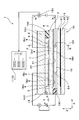
- FIG. 3 is a cross-sectional view of the gas sensor in the first embodiment.
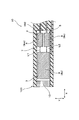
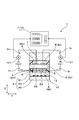
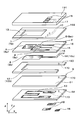
- II-II sectional drawing of FIG. III-III sectional drawing of FIG. 1 is an exploded perspective view of a gas sensor in Embodiment 1.
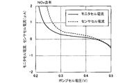
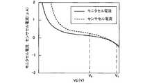
- FIG. The graph showing the relationship between the pump cell voltage, the monitor cell current, and the sensor cell current when measuring the gas containing NOx in Example 1.
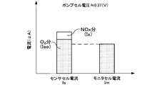
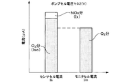
- FIG. 6 is a graph showing a breakdown of sensor cell current and monitor cell current when Vp is about 0.37 V in FIG. 5.
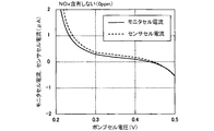
- the graph showing the relationship between the pump cell voltage, the monitor cell current, and the sensor cell current when measuring a gas not containing NOx in Example 1.
- FIG. 3 is a graph showing the relationship between pump cell voltage Vp and Im, Is, Im-Is, Im- ⁇ Is when measuring a gas not containing NOx in Example 1.
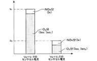
- FIG. The graph showing the breakdown of the sensor cell current and the monitor cell current when the gas containing NOx in Example 1 is measured at Vp of about 0.2V.
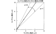
- 11 is a graph showing a correlation between the monitor cell current and the sensor cell current shown in FIG. In Example 2, when measuring the gas containing NOx, and the pump cell voltage, the relationship between the monitor cell current and the sensor cell current, expressed with V1, V2, Im 1, Im 2, Is 1, Is 2 value Graph.
- the graph showing the breakdown of the sensor cell current when the pump cell voltage Vp is set to V1 and V2 shown in FIG.
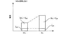
- 16 is a graph showing a breakdown of
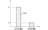
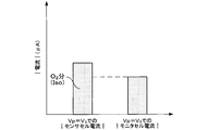
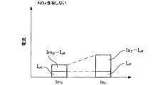
- Example 4 a graph representing the breakdown of Im 2 and Is 2.
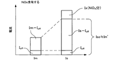
- the graph showing the breakdown of Im and Is when the gas containing NOx in Example 4 is measured.
- the gas concentration detection device can be, for example, a NOx concentration detection device for measuring the concentration of NOx contained in automobile exhaust gas.
- Example 1 An embodiment relating to the gas concentration detection apparatus will be described with reference to FIGS.
- the gas concentration detection device 1 of this example includes a gas sensor 10 and a calculation unit 11.
- the tip 100 of the gas sensor 10 is exposed to the gas g.
- the calculation unit 11 calculates the concentration of a predetermined gas component contained in the gas g using the output current of the gas sensor 10.
- the gas sensor 10 includes a gas chamber 7, a reference gas chamber 12, a solid electrolyte body 2, and a plurality of electrodes 8.
- Gas g is introduced into the gas chamber 7. Further, a reference gas such as the atmosphere is introduced into the reference gas chamber 7.
- the solid electrolyte body 2 is interposed between the gas chamber 7 and the reference gas chamber 12.
- the solid electrolyte body 2 is made of a material having oxygen ion conductivity.
- the electrodes 8 are formed on both surfaces of the solid electrolyte body 2.
- a pump cell 3, a monitor cell 4, and a sensor cell 5 are formed by the solid electrolyte body 2 and the electrode 8.
- the pump cell 3 is a cell that adjusts the oxygen concentration in the gas g in the gas chamber 7.
- the monitor cell 4 is a cell through which an amount of current corresponding to the oxygen concentration in the gas g flows.
- the sensor cell 5 is a cell through which a total current of an amount of current corresponding to the oxygen concentration in the gas g and an amount of current corresponding to the concentration of the predetermined gas component flows.
- the monitor cell current Im flows through the monitor cell 4, and the sensor cell current Is flows through the sensor cell 5.
- the sensor cell current Is includes an oxygen-induced current Iso (see FIG. 6) that is a component due to the oxygen concentration and a predetermined gas-induced current Ix that is a component due to the concentration of the predetermined gas component.
- the calculation unit 11 performs a correction process so that the value of the monitor cell current Im approaches the value of the oxygen-induced current Iso.
- the predetermined gas-derived current Ix is obtained by subtracting the corrected value of the monitor cell current Im ′ from the sensor cell current Is. Using the value of the predetermined gas-induced current Ix, the concentration of the predetermined gas component in the gas g is calculated.
- the gas concentration detection device 1 of this example is a NOx concentration detection device for measuring the NOx concentration contained in the exhaust gas of automobiles. That is, the gas g is an automobile exhaust gas, and the predetermined gas component is NOx.
- the entire gas sensor 10 is housed in a cylindrical case (not shown) and is attached to an exhaust pipe of an automobile. The front end 100 of the gas sensor 10 is inserted into the exhaust pipe, and the rear end portion is exposed to the atmosphere as the reference gas.
- the electrode 8 includes a pump electrode 8 p, a monitor electrode 8 m, a sensor electrode 8 s formed on the main surface 21 of the solid electrolyte body 2 on the gas chamber 7 side, and a reference for the solid electrolyte body 2. And a reference electrode 8b formed on the main surface of the gas chamber 12 side.
- the pump cell 3 is formed by the solid electrolyte body 2, the pump electrode 8p, and the reference electrode 8b.
- the monitor cell 4 is formed by the solid electrolyte body 2, the monitor electrode 8m, and the reference electrode 8b.
- the sensor cell 5 is formed by the solid electrolyte body 2, the sensor electrode 8s, and the reference electrode 8b.
- the gas g is introduced into the gas chamber 7 through the diffusion resistance layer 13. Since the gas g contains oxygen molecules, the pump cell 3 is used to discharge oxygen molecules. That is, a DC voltage is applied between the reference electrode 8b and the pump electrode 8p so that the reference electrode 8b has a high potential. If it does in this way, an oxygen molecule will be reduced in pump electrode 8p, and it will become oxygen ion, and will be exhausted to standard gas room 12 by a pumping action. By adjusting the magnitude of the DC voltage applied to the pump cell 3, the oxygen concentration in the gas chamber 7 is controlled.
- the gas g having a reduced oxygen concentration is introduced into the monitor cell 4 and the sensor cell 5. Since the gas g contains oxygen molecules that could not be exhausted in the pump cell 3, the concentration of the oxygen molecules is measured by the monitor cell 4. As shown in FIG. 3, in the monitor cell 4, a DC voltage is applied between the reference electrode 8b and the monitor electrode 8m so that the reference electrode 8b has a high potential. If it does in this way, the oxygen molecule contained in gas g will be reduced and it will become oxygen ion, and will be exhausted to standard gas room 12 by pumping action.
- the monitor electrode 8m is formed of a Pt—Au cermet electrode that is inert to NOx decomposition, so that the current flowing through the monitor cell 4 (monitor cell current Im) is the concentration of oxygen molecules contained in the gas g. Only, not depending on the concentration of NOx.
- a DC voltage is applied between the reference electrode 8b and the sensor electrode 8s so that the reference electrode 8b has a high potential.
- the sensor electrode 8s is formed of a Pt—Rh cermet electrode that is active in decomposing NOx, oxygen molecules and NOx molecules are reduced to oxygen ions on the sensor electrode 8s, respectively, and pumping action. To the reference gas chamber 12. Therefore, the current flowing through the sensor cell 5 (sensor cell current Is) depends on both the concentration of oxygen molecules and the concentration of NOx molecules.
- the pump cell voltage Vp is set to a predetermined value, for example, about 0.37V.
- the sensor cell current Is includes the predetermined gas-induced current Ix resulting from the concentration of the predetermined gas component, and And an oxygen-induced current Iso caused by the oxygen concentration. Further, since the monitor cell 4 is active only with respect to oxygen, the monitor cell current Im does not include a component due to the concentration of the predetermined gas component.
- the monitor cell current Im is slightly smaller than the oxygen-induced current Iso. That is, the monitor cell 4 and the sensor cell 5 have different sensitivities to the oxygen concentration. This is because the monitor cell 4 and the sensor cell 5 are made of different materials for the electrode 8, and the area of the electrode 8 includes manufacturing variations. Therefore, the predetermined gas-induced current Ix cannot be accurately calculated by simply subtracting the monitor cell current Im from the sensor cell current Is. Therefore, the concentration of the predetermined gas component cannot be accurately calculated.
- the correction process is performed so that the monitor cell current Im approaches the oxygen-induced current Iso.
- the calculation unit 11 calculates the predetermined gas-induced current Ix by substituting the measured sensor cell current Is, the monitor cell current Im, and the sensitivity ratio ⁇ into the following equation.
- Is- ⁇ Im Ix
- the sensitivity ratio ⁇ needs to be measured and memorized because there are variations due to individual differences of the gas sensors 10. For example, when the gas concentration detection device 1 is manufactured and shipped, the atmosphere not containing a predetermined gas component is measured as the gas g. Then, the sensitivity ratio ⁇ is calculated using the obtained sensor cell current Is and monitor cell current Im.
- the oxygen-induced current Iso cannot be directly measured.
- the sensor cell current Is the oxygen-induced current Iso.
- the pump cell voltage Vp is changed stepwise in a state where the gas g does not contain a predetermined gas component. Thereby, a plurality of states in which the oxygen concentrations of the gas g in the gas chamber 7 are different from each other are created. Then, the monitor cell current Im and the sensor cell current Is are measured in each state.
- FIG. 8 shows the correlation between the monitor cell current Im and the sensor cell current Is thus obtained.
- the sensitivity ratio ⁇ depends on individual differences of the gas sensors 10. As shown in FIG. 8, the sensitivity ratio ⁇ , that is, the slope of the straight line takes a value of 1 to 2 in most gas sensors 10.
- the graph of FIG. 9 shows the relationship between the pump cell voltage Vp and Im, Is, Is-Im, Is- ⁇ Im when the gas g not containing NOx is measured.
- the value obtained by simply subtracting the monitor cell current Im from the sensor cell current Is (Is-Im) is in the range where the pump cell voltage Vp is 0.35 to 0.39 V (when the NOx concentration is measured, the pump cell voltage Vp In the range where the variation occurs, the value is relatively large, and is about ⁇ 6 ppm in terms of NOx concentration.
- the value obtained by multiplying the monitor cell current Im by the sensitivity ratio ⁇ and subtracting it from the sensor cell current Is (Is ⁇ Im) is Isp in the range where the pump cell voltage Vp is 0.35 to 0.39V. It becomes a value smaller than ⁇ Im, and can be reduced to ⁇ 1 ppm or less in terms of NOx concentration.
- the sensor cell current Is is the sum of the predetermined gas-induced current Ix and the oxygen-induced current Iso.
- Iso and ⁇ Im can be made almost equal, and the NOx concentration calculated from Iso- ⁇ Im can be made ⁇ 1 ppm or less. Therefore, the predetermined gas-induced current Ix can be accurately calculated.
- the sensitivity ratio ⁇ changes with time. Therefore, it is necessary to periodically measure the sensitivity ratio ⁇ and store the latest sensitivity ratio ⁇ .
- the gas concentration detection device 1 After the gas concentration detection device 1 is attached to a vehicle or the like, it is not possible to measure the atmosphere that does not contain the predetermined gas component (NOx).
- the approximate value ⁇ ′ is periodically calculated. Specifically, it is as follows. That is, when measuring the NOx concentration, the pump cell voltage Vp is set to about 0.37 V as described above, but when measuring the approximate value ⁇ ′ of the sensitivity ratio ⁇ , the pump cell voltage Vp is set to a value lower than this. . For example, the pump cell voltage Vp is set to about 0.2V. If it does in this way, the quantity of the oxygen molecule discharged
- the gas sensor 10 of this example includes only one solid electrolyte body 2.
- a pump electrode 8p, a monitor electrode 8m, a sensor electrode 8s, and a reference electrode 8b are formed on the single solid electrolyte body 2. That is, in this example, three cells of the pump cell 3, the monitor cell 4, and the sensor cell 5 are formed using one solid electrolyte body 2.
- the gas sensor 10 of this example includes an insulating plate 191 made of ceramic or the like, a sheet-like first spacer 192 for forming the gas chamber 7, the solid electrolyte body 2, and a reference gas.
- a sheet-like second spacer 193 for forming the chamber 12 and the heater 6 are stacked in the thickness direction (Z direction) of the heater 6.
- a first notch 79 is formed in the first spacer 192, and the first notch 79 becomes the gas chamber 7.
- the first spacer 192 is provided with a diffusion resistance layer 13. Gas g is introduced from the exhaust pipe into the gas chamber 7 through the diffusion resistance layer 13. The diffusion resistance layer 13 limits the inflow speed of the gas g.
- the second spacer 193 has a second notch 129 formed therein.
- the second notch 129 becomes the reference gas chamber 12.
- the second notch 129 communicates with the external space where the atmosphere exists.
- the first spacer 192 and the second spacer 193 are made of an insulating material such as alumina.
- the pump electrode 8p and the monitor electrode 8m are made of a metal material having low decomposition activity for NOx. Specifically, these electrodes 8p and 8m are made of a porous cermet electrode containing gold Au and platinum Pt as main components. The content of gold Au in the electrodes 8p and 8m is about 1 to 10% by weight.
- the sensor electrode 8s is made of a metal material having a high decomposition activity for NOx. Specifically, the sensor electrode 8s is composed of a porous cermet electrode containing platinum Pt and rhodium Rh as main components.
- the electrode 8 is formed with leads 16 serving as a current path.
- a through hole 17 penetrating in the Z direction is formed in the solid electrolyte body 2, the first spacer 192, and the insulating plate 191.
- a metal plug is formed in the through hole 17.
- a plurality of pads 15 for electrical connection with an external device are formed on the surface of the insulating plate 191. The individual pads 15 and the electrodes 8m, 8s, and 8p are electrically connected through the plugs and the leads 16, respectively.
- the heater 6 includes a ceramic heater sheet 62, a heater electrode 63 that is formed on the surface of the heater sheet 62 and generates heat when energized, and an insulating layer 61 that covers the heater electrode 63.
- the heater 6 is configured to generate heat by heating the heater electrode 63 from the outside and to heat the cells 3, 4 and 5 to the activation temperature.
- a through hole 170 is formed in the second spacer 193, the insulating layer 61, and the heater sheet 62, and a pad 18 is formed on the surface of the heater sheet 62.
- a metal plug is formed in the through hole 170. With this plug, the heater electrode 63 and the reference electrode 8b are electrically connected to the pad 18, respectively.
- the heat generation center of the heater electrode 63 is biased toward the pump cell 3 side. That is, the cells 3, 4, and 5 are configured to be heated using the heater electrode 63 so that the pump cell 3 has a higher temperature than the monitor cell 4 and the sensor cell 5.
- the gas chamber 7 of the present example has a constant interval in the Z direction from the side where the pump cell 3 is formed to the side where the monitor cell 4 and the sensor cell 5 are formed, and X
- the intervals in the width direction (Y direction) orthogonal to both the direction and the Z direction are constant and are integrally formed. That is, in the gas chamber 7, between the side where the pump cell 3 is formed and the side where the monitor cell 4 and the sensor cell 5 are formed, a portion that narrows the Z-direction interval or the Y-direction interval, such as a throttle part or a partition wall. Is not formed.
- the gas g flows from the side on which the pump cell 3 is formed to the side on which the monitor cell 4 and sensor cell 5 are formed without being diffusion-controlled.
- the distance L1 from the pump electrode 8p to the monitor electrode 8m and the distance L2 from the pump electrode 8p to the sensor electrode 8s in the X direction are equal to each other.
- the reference electrode 8b is shared. That is, in the reference electrode 8b, a part constituting the pump cell 3, a part constituting the monitor cell 4, and a part constituting the sensor cell 5 are integrated.
- the calculation unit 11 in the gas concentration detection device 1 of this example corrects the value of the monitor cell current Im so as to approach the value of the oxygen-induced current Iso. For this reason, the concentration of the predetermined gas component can be calculated more accurately. That is, as described above, the sensor cell current Is includes the predetermined gas-derived current Ix and the oxygen-induced current Iso that are components resulting from the concentration of the predetermined gas component. When the correction process is performed, the corrected monitor cell current Im ′ has a value close to the oxygen-induced current Iso.
- the sensor cell current Is and the monitor cell current Im are measured in a state where the gas g does not contain a predetermined gas component.
- the approximate value ⁇ ′ of the sensitivity ratio ⁇ is calculated using the gas g containing a predetermined gas component.
- the pump cell voltage Vp is set lower than the value when calculating the concentration of the predetermined gas component.
- the sensitivity ratio ⁇ changes with time, it is necessary to periodically calculate the sensitivity ratio ⁇ .
- the atmosphere or the like that does not contain the predetermined gas component (NOx) cannot be measured as the gas g.
- a value close to the sensitivity ratio ⁇ can be calculated, so that the concentration of the predetermined gas component can be accurately measured even after the sensitivity ratio ⁇ has changed over time. it can.
- the approximate value ⁇ ′ is preferably calculated when the concentration of the predetermined gas component is as low as possible, such as when the so-called vehicle engine is subjected to fuel cut.
- the gas sensor 10 of this example has a constant interval in the Z direction from the side where the pump cell 3 is formed to the side where the monitor cell 4 and the sensor cell 5 are formed.
- the intervals in the Y direction are constant and are integrally formed. That is, in the gas chamber 7, between the side where the pump cell 3 is formed and the side where the monitor cell 4 and the sensor cell 5 are formed, a portion that narrows the Z-direction interval or the Y-direction interval, such as a throttle part or a partition wall. Is not formed. Therefore, the gas g can be flowed from the pump cell 3 to the monitor cell 4 and the sensor cell 5 without being diffusion controlled. Therefore, when the concentration of the predetermined gas component changes, the change can be detected immediately. That is, the responsiveness of the gas sensor 10 can be improved.
- the pump cell 3, the monitor cell 4 and the sensor cell 5 share one solid electrolyte body 2. Therefore, the number of solid electrolyte bodies 2 can be reduced to one, and the manufacturing cost of the gas sensor 10 can be reduced.
- the calculation method is changed when the approximate value ⁇ ′ of the sensitivity ratio ⁇ is calculated using the gas g containing a predetermined gas component.
- a first voltage V1 and a second voltage V2 having different values are applied to the pump cell 3.
- the monitor cell current Im 1 and the sensor cell current Is 1 in a state obtained by adding a first voltage V1 is measured to measure the monitor cell current Im 2 and the sensor cell current Is 2 in the state plus the second voltage V2.
- the sensor cell currents Is 1 and Is 2 include a predetermined gas-derived current Ix that is a component caused by the concentration of the predetermined gas component and an oxygen-induced current Iso that is a component caused by the oxygen concentration. Since the sensor cell currents Is 1 and Is 2 are values measured by changing the pump cell voltage Vp, the values of the oxygen-induced currents Iso are different from each other. That is, when the pump cell voltage Vp is low (first voltage V1), the oxygen concentration in the gas g is high, and thus the oxygen-induced current Iso is high. Further, when the pump cell voltage Vp is high (second voltage V2), the oxygen concentration in the gas g is low, so that the oxygen-induced current Iso is low.
- the predetermined gas-induced current Ix can be erased, so that it is not affected by the concentration of the predetermined gas component. Therefore, the approximate value ⁇ ′ can be calculated as a value very close to the sensitivity ratio ⁇ .
- the concentration of the predetermined gas component can be calculated with high accuracy using the following equation, as in the first embodiment.
- Is- ⁇ 'Im Ix '
- Example 3 the calculation method is changed when the approximate value ⁇ ′ of the sensitivity ratio ⁇ is calculated using the gas g containing a predetermined gas component.
- the pump cell voltage Vp is set to a value (V3) higher than the value (V0) when calculating the concentration of the predetermined gas component. If it does in this way, NOx which is a predetermined gas component will be decomposed
- the sensor cell current Is does not include the predetermined gas-derived current Ix, but only the oxygen-induced current Iso. Therefore, the approximate value ⁇ ′ of the sensitivity ratio ⁇ can be calculated using the following equation.
- Example 4 the calculation method of the predetermined gas-induced current Ix is changed. It is known that an offset current I off flows through the monitor cell 4 and the sensor cell 5 regardless of the presence or absence of oxygen and a predetermined gas component.
- the offset current I off is considered to be caused by electronic conduction or the like generated between the solid electrolyte body 2 and the electrode 8.
- the monitor cell current Im is corrected on the assumption that the offset current I off is included in the monitor cell current Im and the sensor cell current Is. The details will be described below.
- the sensor cell current Is and the monitor cell current Im are measured using the atmosphere not containing NOx.
- the first voltage V1 and the second voltage V2 which are different from each other are applied to the pump cell 3 (see FIG. 17).
- the concentration of O 2 in the gas chamber 7 is higher than when the second voltage V2, which is a higher voltage, is applied.
- the sensor cell current Is 1 and monitor cell current Im 1 when applying a first voltage V1 than the sensor cell current Is 2 and monitor cell current Im 2 at the time of applying a second voltage V2, a large value.
- the monitor cell currents Im 1 and Im 2 (see FIG. 19) and the sensor cell currents Is 1 and Is 2 include the offset current I off . Since the offset current I off does not depend on the oxygen concentration, the offset currents I off included in the currents Im 1 , Im 2 , Is 1 , Is 2 are almost the same.
- the components (Im 1 -I off ) and (Is 1 -I off ) excluding the offset current I off are sensitive to the oxygen concentration. Only.
- the subtracted value sensitivity ratio ⁇ is constant even when the pump cell voltage Vp is changed and the oxygen concentration in the gas chamber 7 is changed (see FIG. 19).
- the calculation unit 11 of this example calculates the subtraction value sensitivity ratio ⁇ and the offset current I off using the above formula, and stores these values.
- the calculation unit 11 measures the monitor cell current Im and the sensor cell current Is as shown in FIG. 20 when measuring the NOx concentration.
- the calculation unit 11 corrects the measured value of the monitor cell current Im so as to approach the value of the oxygen-induced current Iso using the following formula.
- Im ′ ⁇ (Im ⁇ I off ) + I off
- the calculation unit 11 subtracts the correction value Im ′ of the monitor cell current Im from the sensor cell current Is using the following equation. Thereby, the predetermined gas-induced current Ix is calculated.
- the predetermined gas-induced current Ix can be accurately obtained, and the concentration of the predetermined gas component can be accurately calculated.
- the configuration and operational effects are the same as those of the first embodiment.
- an approximate value ⁇ ′ of the subtraction value sensitivity ratio ⁇ and an approximate value I off ′ of the offset current I off are measured using a gas g containing NOx.
- the subtraction value sensitivity ratio ⁇ and the offset current I off change over time.
- the gas g containing NOx by using the gas g containing NOx, the approximate value ⁇ ′ of the subtraction value sensitivity ratio ⁇ and the approximate value I off ′ of the offset current I off are periodically measured, and the values are updated. I have to.
- the sensor cell currents Is 3 and Is 4 are values obtained by measuring the gas g having the same concentration of the predetermined gas component, the predetermined gas-derived currents Ix included in the sensor cell currents Is 3 and Is 4 are equal to each other.
- the offset currents I off are also equal to each other. In the numerator of the above formula (2), since Is 3 -Is 4 is calculated, Ix and I off are eliminated. Similarly, as shown in FIG. 22, the offset currents I off included in the monitor cell currents Im 3 and Im 4 are equal to each other. In the denominator of the above formula (2), since Im 3 -Im 4 is calculated, I off can be eliminated.
- the offset current I off and the predetermined gas-induced current Ix included in each of the currents Is 3 , Is 4 , Im 3 , and Im 4 can be eliminated, and the subtracted value sensitivity ratio ⁇ Can be calculated with relatively high accuracy.
- the calculation unit 11 measures the sensor cell current Is and the monitor cell current Im when measuring the concentration of the predetermined gas component (NOx). Then, the value of the monitor cell current Im is corrected so as to approach the value of the oxygen-induced current Iso using the following formula.
- Im ′ ⁇ ′ (Im ⁇ I off ′) + I off ′
- the calculation unit 11 subtracts the correction value Im ′ of the monitor cell current Im from the sensor cell current Is using the following equation.
- an approximate value Ix ′ of the predetermined gas-induced current Ix is calculated, and the concentration of the predetermined gas component is calculated using the approximate value Ix ′.
- the approximate value Ix ′ of the predetermined gas-induced current Ix can be calculated using the approximate values ⁇ ′ and I off ′ that are periodically updated, even if the characteristics of the gas sensor 10 change over time, It becomes possible to accurately measure the gas concentration.
- the configuration and operational effects are the same as those of the first embodiment.
Landscapes
- Chemical & Material Sciences (AREA)
- Life Sciences & Earth Sciences (AREA)
- Health & Medical Sciences (AREA)
- Physics & Mathematics (AREA)
- Chemical Kinetics & Catalysis (AREA)
- Electrochemistry (AREA)
- Molecular Biology (AREA)
- Analytical Chemistry (AREA)
- Biochemistry (AREA)
- General Health & Medical Sciences (AREA)
- General Physics & Mathematics (AREA)
- Immunology (AREA)
- Pathology (AREA)
- Measuring Oxygen Concentration In Cells (AREA)
Abstract
Description
上記ガスセンサは、上記ガスが導入されるガス室と、基準ガスが導入される基準ガス室と、上記ガス室と上記基準ガス室との間に介在し酸素イオン伝導性を有する固体電解質体と、該固体電解質体の両面に設けられた複数の電極とを備え、
上記固体電解質体と上記電極とにより、上記ガス室における上記ガスの酸素濃度を調整するポンプセルと、上記ガス中の酸素濃度に対応した量の電流が流れるモニタセルと、上記ガス中の酸素濃度に対応した量の電流と上記所定ガス成分の濃度に対応した量の電流との合計の電流が流れるセンサセルとを形成してあり、
上記算出部は、上記モニタセルに流れる電流であるモニタセル電流Imの値を、上記センサセルに流れる電流であるセンサセル電流Isのうち酸素濃度に起因する成分である酸素起因電流Isoの値に近づけるように補正し、その補正値Im’を上記センサセル電流Isから減算することにより、上記センサセル電流Isのうち上記所定ガス成分の濃度に起因する成分である所定ガス起因電流Ixを求めて、上記ガス中の上記所定ガス成分の濃度を算出するよう構成されていることを特徴とするガス濃度検出装置にある。
そのため、所定ガス成分の濃度をより正確に算出することが可能になる。すなわち、上述したように、センサセル電流Isには、所定ガス成分の濃度に起因する成分である所定ガス起因電流Ixと、上記酸素起因電流Isoとが含まれる。上記補正処理を行うと、補正後のモニタセル電流Im’は、酸素起因電流Isoに近い値になる。そのため、補正後のモニタセル電流Im’をセンサセル電流Is(=Ix+Iso)から減算すれば、Is-Im’=(Ix+Iso)-Im’≒Ixとなり、正確な所定ガス起因電流Ixを算出することができる。そのため、所定ガス成分の濃度を正確に算出することが可能になる。
上記ガス濃度検出装置に係る実施例について、図1~図11を用いて説明する。図1~図4に示すごとく、本例のガス濃度検出装置1は、ガスセンサ10と、算出部11とを備える。ガスセンサ10は、その先端100がガスgに曝されている。算出部11は、ガスセンサ10の出力電流を用いて、ガスgに含まれる所定のガス成分の濃度を算出する。
Is-αIm=Ix
そして、得られた所定ガス起因電流Ixを用いて、所定ガス成分の濃度を算出する。なお、Is-αIm=(Ix+Iso)-Iso/Im・Im=Ixであるため、Is-αImとIxとは互いに等しい。
α=Iso/Im=Is/Im
Is-α’Im=Ix’
そのため、所定ガス成分の濃度をより正確に算出することが可能になる。すなわち、上述したように、センサセル電流Isには、所定ガス成分の濃度に起因する成分である所定ガス起因電流Ixと、酸素起因電流Isoとが含まれる。上記補正処理を行うと、補正後のモニタセル電流Im’は、酸素起因電流Isoに近い値になる。そのため、補正後のモニタセル電流Im’をセンサセル電流Is(=Ix+Iso)から減算すれば、Is-Im’=(Ix+Iso)-Im’≒Ixとなり、正確な所定ガス起因電流Ixを算出することができる。そのため、所定ガス成分の濃度を正確に算出することが可能になる。
Is-αIm=Ix
そして、得られた所定ガス起因電流Ixを用いて、所定ガス成分の濃度を算出する。
そのため、センサセル電流Is中の所定ガス起因電流Ixは、容易に、かつ確実に算出される。
α=Iso/Im=Is/Im
そのため、複数の測定データを用いて感度比αを算出することで、より正確な感度比αを求めることが可能になる。
Is/Im=α’
そのため、所定ガス成分が含まれているガスgを用いて、感度比αに近い値である、近似値α’を算出することができる。上述したように、感度比αは経時変化するため、定期的に感度比αを算出する必要がある。また、ガス濃度検出装置を一旦、車両等に取り付けた後は、所定ガス成分(NOx)を含有しない大気等を、ガスgとして測定することができない。本例では、ガスgに所定ガス成分が含まれていても、感度比αに近い値を算出できるため、感度比αが経時変化した後でも、所定ガス成分の濃度を正確に測定することができる。
なお、上記近似値α’の算出は、いわゆる車両のエンジンがフューエルカットを受けている時のように、所定ガス成分の濃度がなるべく低くなる時に行うことが好ましい。
そのため、ポンプセル3からモニタセル4及びセンサセル5へ、ガスgを拡散律速することなく流すことができる。したがって、所定ガス成分の濃度が変化したときに、その変化をすぐに検出することが可能になる。つまり、ガスセンサ10の応答性を高めることが可能になる。
以下の実施例においては、図面に用いた符号のうち、実施例1において用いた符号と同一のものは、特に示さない限り、実施例1と同様の構成要素を表す。
(Is1-Is2)/(Im1-Im2)=α’ ・・・(1)
Is-α’Im=Ix’
本例は、所定ガス成分を含有するガスgを用いて感度比αの近似値α’を算出するときの、算出方法を変更した例である。図15に示すごとく、本例では、近似値α’を算出するときに、ポンプセル電圧Vpを、所定ガス成分の濃度を算出するときの値(V0)よりも高い値(V3)にする。このようにすると、ポンプ電極8p(図1、図2参照)において所定ガス成分であるNOxが分解される。この状態でモニタセル電流Imとセンサセル電流Isとを測定する。この状態では、ガスg中の所定ガス成分が分解されているので、図16に示すごとく、センサセル電流Isには所定ガス起因電流Ixが含まれず、酸素起因電流Isoのみとなる。そのため、下記式を用いて、感度比αの近似値α’を算出することが可能になる。
α’=Iso/Im=Is/Im
なお、ポンプセル電圧Vpを高くしすぎると、ガスgに含まれるH2Oがポンプ電極8pにおいて分解してH2ガスが発生し、このH2ガスがモニタセル4及びセンサセル5を流れる。そのため、モニタセル電流Imとセンサセル電流Isとがマイナスの値になる。このときの値を用いて感度比を算出すると、H2の感度比が算出されてしまう。したがって、O2の感度比αを求めるには、モニタセル電流Imとセンサセル電流Isとがプラスになっているときの値を用いる必要がある。
本例は、所定ガス起因電流Ixの算出方法を変更した例である。モニタセル4及びセンサセル5には、酸素および所定ガス成分の有無に関わらず、オフセット電流Ioffが流れることが知られている。オフセット電流Ioffは、固体電解質体2と電極8との間に生じる電子伝導等が原因だと考えられている。本例では、モニタセル電流Im及びセンサセル電流Isにオフセット電流Ioffが含まれていることを前提として、モニタセル電流Imを補正している。以下、詳説する。
β=(Is1-Ioff)/(Im1-Ioff)
β=(Is2-Ioff)/(Im2-Ioff)
したがって、βは一般的に、下記式のように定義することができる。
β=(Is-Ioff)/(Im-Ioff)
Is1=β(Im1-Ioff)+Ioff
Is2=β(Im2-Ioff)+Ioff
β=(Is1-Is2)/(Im1-Im2)
Ioff=(Is1-βIm1)/(1-β)
本例の算出部11は、上記式を用いて減算値感度比βとオフセット電流Ioffとを算出し、これらの値を記憶しておく。
Im’=β(Im-Ioff)+Ioff
Ix=Is-Im’=Is-{β(Im-Ioff)+Ioff}
その他、実施例1と同様の構成および作用効果を有する。
本例は、NOxを含有するガスgを用いて、減算値感度比βの近似値β’、及びオフセット電流Ioffの近似値Ioff’を測定するようにした例である。減算値感度比β及びオフセット電流Ioffは、経年変化する。また、ガス濃度検出装置1を車体等に取り付けた後は、NOxを含有しないガスgを測定する機会が殆ど無い。そのため本例では、NOxを含有するガスgを用いて、減算値感度比βの近似値β’、及びオフセット電流Ioffの近似値Ioff’を定期的に測定し、その値を更新するようにしている。
β’=(Is3-Is4)/(Im3-Im4) ・・・(2)
Ioff’=(Is3-β’Im3)/(1-β’)
Im’=β’(Im-Ioff’)+Ioff’
Ix’=Is-Im’=Is-{β’(Im-Ioff’)+Ioff’}
その他、実施例1と同様の構成および作用効果を有する。
10 ガスセンサ
11 算出部
12 基準ガス室
2 固体電解質体
3 ポンプセル
4 モニタセル
5 センサセル
7 ガス室
8 電極
Im モニタセル電流
Is センサセル電流
Iso 酸素起因電流
Ix 所定ガス起因電流
g ガス
Claims (10)
- ガスに曝されるガスセンサ(10)と、該ガスセンサ(10)の出力を用いて、上記ガスに含まれる所定ガス成分の濃度を算出する算出部(11)とを備えるガス濃度検出装置(1)であって、
上記ガスセンサ(10)は、上記ガスが導入されるガス室(7)と、基準ガスが導入される基準ガス室(12)と、上記ガス室(7)と上記基準ガス室(12)との間に介在し酸素イオン伝導性を有する固体電解質体(2)と、該固体電解質体(2)の両面に設けられた複数の電極(8)とを備え、
上記固体電解質体(2)と上記電極(8)とにより、上記ガス室(7)における上記ガスの酸素濃度を調整するポンプセル(3)と、上記ガス中の酸素濃度に対応した量の電流が流れるモニタセル(4)と、上記ガス中の酸素濃度に対応した量の電流と上記所定ガス成分の濃度に対応した量の電流との合計の電流が流れるセンサセル(5)とを形成してあり、
上記算出部(11)は、上記モニタセル(4)に流れる電流であるモニタセル電流Imの値を、上記センサセル(5)に流れる電流であるセンサセル電流Isのうち酸素濃度に起因する成分である酸素起因電流Isoの値に近づけるように補正し、その補正値Im’を上記センサセル電流Isから減算することにより、上記センサセル電流Isのうち上記所定ガス成分の濃度に起因する成分である所定ガス起因電流Ixを求めて、上記ガス中の上記所定ガス成分の濃度を算出するよう構成されていることを特徴とするガス濃度検出装置(1)。 - 上記算出部(11)は、上記ガスに上記所定ガス成分が含まれない状態において、上記センサセル電流Isと上記モニタセル電流Imとを測定し、下記式(1)を用いて、上記酸素起因電流Isoと上記モニタセル電流Imとの比である感度比αを算出し、
α=Iso/Im=Is/Im (1)
上記算出部(11)は、上記ガスに上記所定ガス成分が含まれている状態において、上記センサセル電流Isと上記モニタセル電流Imとを測定し、下記式(2)を用いて上記所定ガス起因電流Ixを算出して、上記所定ガス成分の濃度を求めるよう構成されていることを特徴とする請求項1に記載のガス濃度検出装置(1)。
Is-αIm=Ix (2) - 上記算出部(11)は、上記ガスに上記所定ガス成分が含まれない状態において、上記ポンプセル(3)に加える電圧を変化させることにより、上記ガス室(7)における上記ガス中の酸素濃度が互いに異なる複数の状態を形成し、各々の状態において上記センサセル電流Isと上記モニタセル電流Imとを測定して、上記感度比αを算出するよう構成されていることを特徴とする請求項2に記載のガス濃度検出装置(1)。
- 上記算出部(11)は、上記ガスに上記所定ガス成分が含まれているときに、上記ポンプセル(3)に加える電圧を、上記所定ガス成分の濃度を算出するときの値よりも低くし、その状態で上記センサセル電流Isと上記モニタセル電流Imとを測定し、下記式(3)を用いることにより、上記感度比αの近似値α’を算出し、
Is/Im=α’ (3)
上記算出部(11)は、上記ガス中の上記所定ガス成分の濃度を検出するときに、上記センサセル電流Isと上記モニタセル電流Imとを測定し、下記式(4)を用いて、上記所定ガス起因電流Ixの近似値Ix’を算出することにより、上記所定ガス成分の濃度を近似的に求めるよう構成されていることを特徴とする請求項2又は請求項3に記載のガス濃度検出装置(1)。
Is-α’Im=Ix’ (4) - 上記算出部(11)は、上記ガスに上記所定ガス成分が含まれているときに、上記ポンプセル(3)に互いに値が異なる第1電圧(V1)と第2電圧(V2)とを加え、上記第1電圧(V1)を加えた状態における上記モニタセル電流Im1及び上記センサセル電流Is1を測定すると共に、上記第2電圧(V2)を加えた状態における上記モニタセル電流Im2及び上記センサセル電流Is2を測定し、下記式(5)を用いて、上記感度比αの近似値α’を算出し、
(Is1-Is2)/(Im1-Im2)=α’ (5)
上記算出部(11)は、上記ガス中の上記所定ガス成分の濃度を検出するときに、上記センサセル電流Isと上記モニタセル電流Imとを測定し、下記式(6)を用いて、上記所定ガス起因電流Ixの近似値Ix’を算出することにより、上記所定ガス成分の濃度を近似的に求めるよう構成されていることを特徴とする請求項2又は請求項3に記載のガス濃度検出装置(1)。
Is-α’Im=Ix’ (6) - 上記算出部(11)は、上記ガスに上記所定ガス成分が含まれているときに、上記ポンプセル(3)に加える電圧を、上記所定ガス成分の濃度を算出するときの値よりも高くし、その状態で上記センサセル電流Isと上記モニタセル電流Imとを測定し、下記式(7)を用いることにより、上記感度比αの近似値α’を算出し、
Is/Im=α’ (7)
上記算出部(11)は、上記ガス中の上記所定ガス成分の濃度を検出するときに、上記センサセル電流Isと上記モニタセル電流Imとを測定し、下記式(8)を用いて、上記所定ガス起因電流Ixの近似値Ix’を算出することにより、上記所定ガス成分の濃度を近似的に求めるよう構成されていることを特徴とする請求項2又は請求項3に記載のガス濃度検出装置(1)。
Is-α’Im=Ix’ (8) - 上記算出部(11)は、上記ガスに上記所定ガス成分が含まれない状態において、上記ポンプセル(3)に互いに値が異なる第1電圧(V1)と第2電圧(V2)とを加え、上記第1電圧(V1)を加えた状態における上記モニタセル電流Im1及び上記センサセル電流Is1を測定すると共に、上記第2電圧(V2)を加えた状態における上記モニタセル電流Im2及び上記センサセル電流Is2を測定し、下記式(9)を用いて、上記センサセル電流Isから、酸素および上記所定ガス成分の有無に関わらず流れる成分であるオフセット電流Ioffを減算した値Is-Ioffと、上記モニタセル電流Imから上記オフセット電流Ioffを減算した値Im-Ioffとの比である減算値感度比βを算出すると共に、下記式(10)を用いて上記オフセット電流Ioffを算出し、
β=(Is1-Is2)/(Im1-Im2) (9)
Ioff=(Is1-βIm1)/(1-β) (10)
上記算出部(11)は、上記ガス中の上記所定ガス成分の濃度を検出するときに、上記センサセル電流Isと上記モニタセル電流Imとを測定し、下記式(11)を用いて上記所定ガス起因電流Ixを算出して、上記所定ガス成分の濃度を求めるよう構成されていることを特徴とする請求項1に記載のガス濃度検出装置(1)。
Ix=Is-{β(Im-Ioff)+Ioff} (11) - 上記算出部(11)は、上記ガスに上記所定ガス成分が含まれているときに、上記ポンプセル(3)に互いに値が異なる第3電圧(V3)と第4電圧(V4)とを加え、上記第3電圧(V3)を加えた状態における上記モニタセル電流Im3及び上記センサセル電流Is3を測定すると共に、上記第4電圧(V4)を加えた状態における上記モニタセル電流Im4及び上記センサセル電流Is4を測定し、下記式(12)を用いて、上記減算値感度比βの近似値β’を算出すると共に、下記式(13)を用いて、上記オフセット電流Ioffの近似値Ioff’を算出し、
β’=(Is3-Is4)/(Im3-Im4) (12)
Ioff’=(Is3-β’Im3)/(1-β’) (13)
上記算出部(11)は、上記ガス中の上記所定ガス成分の濃度を検出するときに、上記センサセル電流Isと上記モニタセル電流Imとを測定し、下記式(14)を用いて、上記所定ガス起因電流Ixの近似値Ix’を算出することにより、上記所定ガス成分の濃度を近似的に求めるよう構成されていることを特徴とする請求項7に記載のガス濃度検出装置(1)。
Ix’=Is-{β’(Im-Ioff’)+Ioff’} (14) - 上記ガス室(7)は、上記ポンプセル(3)を形成した側から、上記モニタセル(4)及び上記センサセル(5)を形成した側にわたって、上記固体電解質体(2)の厚さ方向における間隔が一定であると共に、上記ガスの流れ方向と上記厚さ方向との双方に直交する幅方向における間隔が一定であり、一体的に形成されていることを特徴とする請求項1~請求項8のいずれか1項に記載のガス濃度検出装置(1)。
- 上記ポンプセル(3)と上記モニタセル(4)と上記センサセル(5)とは、1つの上記固体電解質体(2)を共有していることを特徴とする請求項1~請求項9のいずれか1項に記載のガス濃度検出装置(1)。
Priority Applications (4)
| Application Number | Priority Date | Filing Date | Title |
|---|---|---|---|
| US14/914,370 US10073053B2 (en) | 2013-08-30 | 2014-08-29 | Gas concentration measuring apparatus |
| CN201480047011.3A CN105474003B (zh) | 2013-08-30 | 2014-08-29 | 气体浓度检测装置 |
| DE112014003968.3T DE112014003968T5 (de) | 2013-08-30 | 2014-08-29 | Gaskonzentrationsmessvorrichtung |
| US15/947,037 US10113992B2 (en) | 2013-08-30 | 2018-04-06 | Gas concentration measuring apparatus |
Applications Claiming Priority (4)
| Application Number | Priority Date | Filing Date | Title |
|---|---|---|---|
| JP2013-178980 | 2013-08-30 | ||
| JP2013178980 | 2013-08-30 | ||
| JP2014-165752 | 2014-08-18 | ||
| JP2014165752A JP5910683B2 (ja) | 2013-08-30 | 2014-08-18 | ガス濃度検出装置 |
Related Child Applications (2)
| Application Number | Title | Priority Date | Filing Date |
|---|---|---|---|
| US14/914,370 A-371-Of-International US10073053B2 (en) | 2013-08-30 | 2014-08-29 | Gas concentration measuring apparatus |
| US15/947,037 Division US10113992B2 (en) | 2013-08-30 | 2018-04-06 | Gas concentration measuring apparatus |
Publications (1)
| Publication Number | Publication Date |
|---|---|
| WO2015030165A1 true WO2015030165A1 (ja) | 2015-03-05 |
Family
ID=52586712
Family Applications (1)
| Application Number | Title | Priority Date | Filing Date |
|---|---|---|---|
| PCT/JP2014/072719 Ceased WO2015030165A1 (ja) | 2013-08-30 | 2014-08-29 | ガス濃度検出装置 |
Country Status (5)
| Country | Link |
|---|---|
| US (2) | US10073053B2 (ja) |
| JP (1) | JP5910683B2 (ja) |
| CN (1) | CN105474003B (ja) |
| DE (1) | DE112014003968T5 (ja) |
| WO (1) | WO2015030165A1 (ja) |
Cited By (4)
| Publication number | Priority date | Publication date | Assignee | Title |
|---|---|---|---|---|
| JP2018180002A (ja) * | 2015-09-17 | 2018-11-15 | 株式会社デンソー | ガスセンサ |
| WO2020158268A1 (ja) * | 2019-01-31 | 2020-08-06 | 株式会社デンソー | ガスセンサ |
| WO2020158269A1 (ja) * | 2019-01-31 | 2020-08-06 | 株式会社デンソー | ガスセンサ |
| CN113758890A (zh) * | 2021-08-18 | 2021-12-07 | 清华大学 | 一种气体浓度计算方法、装置、设备及存储介质 |
Families Citing this family (12)
| Publication number | Priority date | Publication date | Assignee | Title |
|---|---|---|---|---|
| JP6558109B2 (ja) | 2014-07-25 | 2019-08-14 | 株式会社デンソー | ガス濃度検出装置 |
| JP6485364B2 (ja) | 2015-02-12 | 2019-03-20 | 株式会社デンソー | ガスセンサ |
| WO2017047511A1 (ja) * | 2015-09-17 | 2017-03-23 | 株式会社デンソー | ガスセンサ |
| JP6382178B2 (ja) * | 2015-12-17 | 2018-08-29 | 株式会社Soken | ガスセンサ |
| CN105973965B (zh) * | 2016-05-06 | 2018-06-29 | 武汉科技大学 | 双电池电流型氮氧化物传感器芯片及制备方法 |
| JP6693405B2 (ja) | 2016-12-20 | 2020-05-13 | 株式会社デンソー | ガスセンサ素子およびガスセンサユニット |
| JP6696418B2 (ja) | 2016-12-21 | 2020-05-20 | 株式会社デンソー | ガスセンサ素子及びガスセンサユニット |
| JP6720851B2 (ja) | 2016-12-21 | 2020-07-08 | 株式会社デンソー | ガスセンサ素子およびガスセンサユニット |
| CN111670360A (zh) * | 2018-01-31 | 2020-09-15 | 兴亚株式会社 | 氧传感器元件 |
| JP6998801B2 (ja) * | 2018-03-12 | 2022-02-04 | 日本碍子株式会社 | ガスセンサ |
| KR102874360B1 (ko) * | 2020-05-12 | 2025-10-29 | 피에스에스 주식회사 | 연결 통로가 형성된 하우징을 포함하는 가스 감지 장치 |
| CN111693587A (zh) * | 2020-06-01 | 2020-09-22 | 武汉科技大学 | 一种测量氧分压的集成氧传感器芯片及其制备方法 |
Citations (7)
| Publication number | Priority date | Publication date | Assignee | Title |
|---|---|---|---|---|
| JPS6363964A (ja) * | 1986-09-04 | 1988-03-22 | Nissan Motor Co Ltd | 空燃比検出装置 |
| JPH10206363A (ja) * | 1997-01-16 | 1998-08-07 | Shimadzu Corp | ガス計測装置 |
| JP2000321238A (ja) * | 1996-09-17 | 2000-11-24 | Riken Corp | ガスセンサ |
| JP2004108788A (ja) * | 2002-09-13 | 2004-04-08 | Denso Corp | ガス濃度検出装置 |
| JP2009244048A (ja) * | 2008-03-31 | 2009-10-22 | Ngk Insulators Ltd | ガスセンサおよびその制御装置ならびにNOx濃度測定方法 |
| JP2011058834A (ja) * | 2009-09-07 | 2011-03-24 | Denso Corp | ガスセンサ素子 |
| JP2013148358A (ja) * | 2012-01-17 | 2013-08-01 | Ngk Spark Plug Co Ltd | ガス濃度検出装置の補正係数設定方法およびガス濃度検出装置ならびにガスセンサ |
Family Cites Families (9)
| Publication number | Priority date | Publication date | Assignee | Title |
|---|---|---|---|---|
| JPH03272450A (ja) * | 1990-03-22 | 1991-12-04 | Nissan Motor Co Ltd | 窒素酸化物濃度の計測装置 |
| DE4447033C2 (de) * | 1994-12-28 | 1998-04-30 | Bosch Gmbh Robert | Meßfühler zur Bestimmung des Sauerstoffgehaltes in Gasgemischen |
| JP2000137018A (ja) * | 1998-11-02 | 2000-05-16 | Denso Corp | ガス濃度検出装置とそれに用いるガス濃度センサ |
| JP4682465B2 (ja) * | 2000-10-31 | 2011-05-11 | 株式会社デンソー | ガス濃度検出装置 |
| JP3973900B2 (ja) | 2001-02-08 | 2007-09-12 | 株式会社日本自動車部品総合研究所 | ガスセンサ素子 |
| JP2003083936A (ja) | 2001-06-25 | 2003-03-19 | Denso Corp | ガスセンサ素子 |
| JP4415771B2 (ja) * | 2004-06-28 | 2010-02-17 | 株式会社デンソー | ガス濃度検出装置 |
| CN1959396A (zh) * | 2005-11-04 | 2007-05-09 | 株式会社电装 | 气体传感器 |
| JP4874282B2 (ja) | 2008-03-20 | 2012-02-15 | 株式会社デンソー | ガスセンサ制御装置 |
-
2014
- 2014-08-18 JP JP2014165752A patent/JP5910683B2/ja active Active
- 2014-08-29 WO PCT/JP2014/072719 patent/WO2015030165A1/ja not_active Ceased
- 2014-08-29 CN CN201480047011.3A patent/CN105474003B/zh active Active
- 2014-08-29 US US14/914,370 patent/US10073053B2/en active Active
- 2014-08-29 DE DE112014003968.3T patent/DE112014003968T5/de active Pending
-
2018
- 2018-04-06 US US15/947,037 patent/US10113992B2/en active Active
Patent Citations (7)
| Publication number | Priority date | Publication date | Assignee | Title |
|---|---|---|---|---|
| JPS6363964A (ja) * | 1986-09-04 | 1988-03-22 | Nissan Motor Co Ltd | 空燃比検出装置 |
| JP2000321238A (ja) * | 1996-09-17 | 2000-11-24 | Riken Corp | ガスセンサ |
| JPH10206363A (ja) * | 1997-01-16 | 1998-08-07 | Shimadzu Corp | ガス計測装置 |
| JP2004108788A (ja) * | 2002-09-13 | 2004-04-08 | Denso Corp | ガス濃度検出装置 |
| JP2009244048A (ja) * | 2008-03-31 | 2009-10-22 | Ngk Insulators Ltd | ガスセンサおよびその制御装置ならびにNOx濃度測定方法 |
| JP2011058834A (ja) * | 2009-09-07 | 2011-03-24 | Denso Corp | ガスセンサ素子 |
| JP2013148358A (ja) * | 2012-01-17 | 2013-08-01 | Ngk Spark Plug Co Ltd | ガス濃度検出装置の補正係数設定方法およびガス濃度検出装置ならびにガスセンサ |
Cited By (8)
| Publication number | Priority date | Publication date | Assignee | Title |
|---|---|---|---|---|
| JP2018180002A (ja) * | 2015-09-17 | 2018-11-15 | 株式会社デンソー | ガスセンサ |
| WO2020158268A1 (ja) * | 2019-01-31 | 2020-08-06 | 株式会社デンソー | ガスセンサ |
| WO2020158269A1 (ja) * | 2019-01-31 | 2020-08-06 | 株式会社デンソー | ガスセンサ |
| JP2020122764A (ja) * | 2019-01-31 | 2020-08-13 | 株式会社デンソー | ガスセンサ |
| JP2020122763A (ja) * | 2019-01-31 | 2020-08-13 | 株式会社デンソー | ガスセンサ |
| JP7006629B2 (ja) | 2019-01-31 | 2022-01-24 | 株式会社デンソー | ガスセンサ |
| JP7010250B2 (ja) | 2019-01-31 | 2022-01-26 | 株式会社デンソー | ガスセンサ |
| CN113758890A (zh) * | 2021-08-18 | 2021-12-07 | 清华大学 | 一种气体浓度计算方法、装置、设备及存储介质 |
Also Published As
| Publication number | Publication date |
|---|---|
| DE112014003968T5 (de) | 2016-05-25 |
| CN105474003A (zh) | 2016-04-06 |
| JP2015064341A (ja) | 2015-04-09 |
| US20160209358A1 (en) | 2016-07-21 |
| US10073053B2 (en) | 2018-09-11 |
| CN105474003B (zh) | 2017-12-29 |
| US10113992B2 (en) | 2018-10-30 |
| JP5910683B2 (ja) | 2016-04-27 |
| US20180224396A1 (en) | 2018-08-09 |
Similar Documents
| Publication | Publication Date | Title |
|---|---|---|
| JP5910683B2 (ja) | ガス濃度検出装置 | |
| JP6203687B2 (ja) | ガスセンサ | |
| JP5253165B2 (ja) | ガスセンサ及び窒素酸化物センサ | |
| JP6058153B2 (ja) | ポンプセルを含む固体電解質センサ素子を動作させるための方法 | |
| JP5119305B2 (ja) | ガスセンサ制御装置及びガスセンサ制御方法 | |
| US8398836B2 (en) | Gas sensor | |
| JP2002310987A (ja) | ガスセンサ素子 | |
| JP5587919B2 (ja) | ガス濃度検出装置の補正係数設定方法およびガス濃度検出装置ならびにガスセンサ | |
| US10088448B2 (en) | Gas sensor element | |
| US20090242402A1 (en) | NOx SENSOR | |
| WO2015029842A1 (ja) | ガス濃度検出装置 | |
| JP5247780B2 (ja) | ガスセンサの校正方法 | |
| US9523655B2 (en) | Gas concentration detector | |
| US12140579B2 (en) | Gas sensor and gas sensor operation control method | |
| JP2003083936A (ja) | ガスセンサ素子 | |
| US10088446B2 (en) | Gas sensor | |
| JP6511405B2 (ja) | ガスセンサ | |
| CN106338541B (zh) | SOx浓度检测装置 | |
| JP2001330586A (ja) | ガスセンサ素子 | |
| JP2004205357A (ja) | ガス濃度の検出方法 | |
| JP5501901B2 (ja) | 窒素酸化物センサおよび窒素酸化物検出方法 | |
| JP3520217B2 (ja) | ガスセンサ | |
| JP2004093200A (ja) | ガスセンサ素子 | |
| JP2000171433A (ja) | 可燃性ガス濃度測定デバイス |
Legal Events
| Date | Code | Title | Description |
|---|---|---|---|
| WWE | Wipo information: entry into national phase |
Ref document number: 201480047011.3 Country of ref document: CN |
|
| 121 | Ep: the epo has been informed by wipo that ep was designated in this application |
Ref document number: 14839680 Country of ref document: EP Kind code of ref document: A1 |
|
| WWE | Wipo information: entry into national phase |
Ref document number: 14914370 Country of ref document: US |
|
| WWE | Wipo information: entry into national phase |
Ref document number: 1120140039683 Country of ref document: DE Ref document number: 112014003968 Country of ref document: DE |
|
| 122 | Ep: pct application non-entry in european phase |
Ref document number: 14839680 Country of ref document: EP Kind code of ref document: A1 |